EP4421972A2 - Gehäuseanordnung einer knopfzelle, knopfzelle und elektronisches produkt - Google Patents
Gehäuseanordnung einer knopfzelle, knopfzelle und elektronisches produkt Download PDFInfo
- Publication number
- EP4421972A2 EP4421972A2 EP24187599.6A EP24187599A EP4421972A2 EP 4421972 A2 EP4421972 A2 EP 4421972A2 EP 24187599 A EP24187599 A EP 24187599A EP 4421972 A2 EP4421972 A2 EP 4421972A2
- Authority
- EP
- European Patent Office
- Prior art keywords
- housing
- button cell
- conductive
- tab
- cell
- Prior art date
- Legal status (The legal status is an assumption and is not a legal conclusion. Google has not performed a legal analysis and makes no representation as to the accuracy of the status listed.)
- Pending
Links
Images




Classifications
-
- H—ELECTRICITY
- H01—ELECTRIC ELEMENTS
- H01M—PROCESSES OR MEANS, e.g. BATTERIES, FOR THE DIRECT CONVERSION OF CHEMICAL ENERGY INTO ELECTRICAL ENERGY
- H01M50/00—Constructional details or processes of manufacture of the non-active parts of electrochemical cells other than fuel cells, e.g. hybrid cells
- H01M50/10—Primary casings; Jackets or wrappings
- H01M50/102—Primary casings; Jackets or wrappings characterised by their shape or physical structure
- H01M50/109—Primary casings; Jackets or wrappings characterised by their shape or physical structure of button or coin shape
-
- H—ELECTRICITY
- H01—ELECTRIC ELEMENTS
- H01M—PROCESSES OR MEANS, e.g. BATTERIES, FOR THE DIRECT CONVERSION OF CHEMICAL ENERGY INTO ELECTRICAL ENERGY
- H01M50/00—Constructional details or processes of manufacture of the non-active parts of electrochemical cells other than fuel cells, e.g. hybrid cells
- H01M50/20—Mountings; Secondary casings or frames; Racks, modules or packs; Suspension devices; Shock absorbers; Transport or carrying devices; Holders
- H01M50/204—Racks, modules or packs for multiple batteries or multiple cells
- H01M50/207—Racks, modules or packs for multiple batteries or multiple cells characterised by their shape
- H01M50/216—Racks, modules or packs for multiple batteries or multiple cells characterised by their shape adapted for button or coin cells
-
- H—ELECTRICITY
- H01—ELECTRIC ELEMENTS
- H01M—PROCESSES OR MEANS, e.g. BATTERIES, FOR THE DIRECT CONVERSION OF CHEMICAL ENERGY INTO ELECTRICAL ENERGY
- H01M50/00—Constructional details or processes of manufacture of the non-active parts of electrochemical cells other than fuel cells, e.g. hybrid cells
- H01M50/10—Primary casings; Jackets or wrappings
- H01M50/172—Arrangements of electric connectors penetrating the casing
- H01M50/174—Arrangements of electric connectors penetrating the casing adapted for the shape of the cells
- H01M50/181—Arrangements of electric connectors penetrating the casing adapted for the shape of the cells for button or coin cells
-
- H—ELECTRICITY
- H01—ELECTRIC ELEMENTS
- H01M—PROCESSES OR MEANS, e.g. BATTERIES, FOR THE DIRECT CONVERSION OF CHEMICAL ENERGY INTO ELECTRICAL ENERGY
- H01M50/00—Constructional details or processes of manufacture of the non-active parts of electrochemical cells other than fuel cells, e.g. hybrid cells
- H01M50/10—Primary casings; Jackets or wrappings
- H01M50/183—Sealing members
- H01M50/184—Sealing members characterised by their shape or structure
-
- H—ELECTRICITY
- H01—ELECTRIC ELEMENTS
- H01M—PROCESSES OR MEANS, e.g. BATTERIES, FOR THE DIRECT CONVERSION OF CHEMICAL ENERGY INTO ELECTRICAL ENERGY
- H01M50/00—Constructional details or processes of manufacture of the non-active parts of electrochemical cells other than fuel cells, e.g. hybrid cells
- H01M50/10—Primary casings; Jackets or wrappings
- H01M50/183—Sealing members
- H01M50/186—Sealing members characterised by the disposition of the sealing members
-
- H—ELECTRICITY
- H01—ELECTRIC ELEMENTS
- H01M—PROCESSES OR MEANS, e.g. BATTERIES, FOR THE DIRECT CONVERSION OF CHEMICAL ENERGY INTO ELECTRICAL ENERGY
- H01M50/00—Constructional details or processes of manufacture of the non-active parts of electrochemical cells other than fuel cells, e.g. hybrid cells
- H01M50/10—Primary casings; Jackets or wrappings
- H01M50/183—Sealing members
- H01M50/19—Sealing members characterised by the material
- H01M50/193—Organic material
-
- H—ELECTRICITY
- H01—ELECTRIC ELEMENTS
- H01M—PROCESSES OR MEANS, e.g. BATTERIES, FOR THE DIRECT CONVERSION OF CHEMICAL ENERGY INTO ELECTRICAL ENERGY
- H01M50/00—Constructional details or processes of manufacture of the non-active parts of electrochemical cells other than fuel cells, e.g. hybrid cells
- H01M50/50—Current conducting connections for cells or batteries
- H01M50/531—Electrode connections inside a battery casing
- H01M50/538—Connection of several leads or tabs of wound or folded electrode stacks
-
- Y—GENERAL TAGGING OF NEW TECHNOLOGICAL DEVELOPMENTS; GENERAL TAGGING OF CROSS-SECTIONAL TECHNOLOGIES SPANNING OVER SEVERAL SECTIONS OF THE IPC; TECHNICAL SUBJECTS COVERED BY FORMER USPC CROSS-REFERENCE ART COLLECTIONS [XRACs] AND DIGESTS
- Y02—TECHNOLOGIES OR APPLICATIONS FOR MITIGATION OR ADAPTATION AGAINST CLIMATE CHANGE
- Y02E—REDUCTION OF GREENHOUSE GAS [GHG] EMISSIONS, RELATED TO ENERGY GENERATION, TRANSMISSION OR DISTRIBUTION
- Y02E60/00—Enabling technologies; Technologies with a potential or indirect contribution to GHG emissions mitigation
- Y02E60/10—Energy storage using batteries
Definitions
- the present disclosure relates to the field of cell technology and, in particular, to a housing assembly of button cell, a button cell and an electronic product.
- button cells have been widely used in various fields of daily life, such as wearable product field, electronic product field and medical product field.
- the present disclosure provides a housing assembly of button cell, a button cell and an electronic product. Sealability of the housing assembly of button cell is relatively good, which is beneficial to improving quality and performance of the button cell.
- the present disclosure provides a housing assembly of button cell, including a housing and a conductive part, the housing having a holding cavity that is capable of holding a cell of the button cell, the cell having a first tab and a second tab, the housing being provided with a through hole, the conductive part being positioned at and blocking the through hole, and the conductive part and the through hole being sealed and insulated;
- a housing assembly of button cell includes a housing and a conductive part, where the housing has a holding cavity that is capable of holding a cell of the button cell, and the cell has a first tab and a second tab.
- this sealing method requires fewer sealing setting positions, it will not only make it easy to seal, but also have a relatively small risk of leakage after the sealing setting is completed. Therefore, this sealing method can make the housing assembly of button cell obtain a relatively good sealability, which is beneficial to improving quality and performance of the button cell.
- the conductive part can be set as one or two, so that the design of the button cell can be more flexible.
- the cell can output electrical power outward or input electrical power to the cell through the housing and the one conductive part; or, when the number of the conductive part is two, the housing is provided with the two through holes, and the conductive parts correspond to the through holes one by one, by electrically connecting one of the two conductive parts with the first tab, and electrically connecting the other one of the two conductive parts with the second tab, the cell can output electrical power outward or input electrical power to the cell through the two conductive parts.
- the housing has two oppositely disposed end surfaces, and at least one of the conductive parts is located on the end surfaces.
- the housing has a cylindrical sidewall, which is located between the two oppositely disposed end surfaces, and at least one of the conductive parts is located on the cylindrical sidewall. Further, the outer surface of the cylindrical sidewall has a flat surface extending along a direction of cylindrical generatrix, and at least one of the conductive parts is located on the flat surface.
- At least a part of at least one of the end surfaces protrudes in a direction away from the cell to form a convex surface; at least one of the conductive parts is located on the convex surface.
- the conductive part is a conductive nail penetrated through the through hole.
- the conductive part is a conductive sheet disposed inside the through hole, and an insulating part is provided between the conductive sheet and the edge of the through hole, and a position of the insulating part corresponding to an outer edge of the conductive sheet is provided with a groove into which the outer edge of the conductive sheet can extend.
- hardness of the conductive part is smaller than hardness of the housing.
- the housing includes a first housing and a second housing, the first housing and the second housing enclose together to form the holding cavity, and the first housing and the second housing are integral parts.
- At least a part of a housing wall of the housing has a thinning area, and thickness of the housing wall in the thinning area is smaller than thickness of other parts of the housing wall.
- the present disclosure provides a button cell, including a cell and the housing assembly of button cell as described in any one of the above items.
- a button cell includes a cell and a housing assembly of button cell.
- the housing assembly of button cell includes a housing and a conductive part, where the housing has a holding cavity that is capable of holding a cell of the button cell, and the cell has a first tab and a second tab.
- this sealing method requires fewer sealing setting positions, it will not only make it easy to seal, but also have a relatively small risk of leakage after the sealing setting is completed. Therefore, this sealing method can make the housing assembly of button cell obtain a relatively good sealability, which is beneficial to improving quality and performance of the button cell.
- the conductive part can be set as one or two, so that the design of the button cell can be more flexible.
- the cell can output electrical power outward or input electrical power to the cell through the housing and the one conductive part; or, when the number of the conductive part is two, the housing is provided with the two through holes, and the conductive parts correspond to the through holes one by one, by electrically connecting one of the two conductive parts with the first tab, and electrically connecting the other one of the two conductive parts with the second tab, the cell can output electrical power outward or input electrical power to the cell through the two conductive parts.
- the present disclosure provides an electronic product, including the button cell as described above.
- the electronic product of the present disclosure includes a button cell.
- the button cell includes a cell and a housing assembly of button cell.
- the housing assembly of button cell includes a housing and conductive parts, where the housing has a holding cavity that is capable of holding a cell of the button cell, and the cell has a first tab and a second tab.
- this sealing method requires fewer sealing setting positions, it will not only make it easy to seal, but also have a relatively small risk of leakage after the sealing setting is completed. Therefore, this sealing method can make the housing assembly of button cell obtain a relatively good sealability, which is beneficial to improving quality and performance of the button cell.
- the conductive part can be set as one or two, so that the design of the button cell can be more flexible.
- the cell can output electrical power outward or input electrical power to the cell through the housing and the one conductive part; or, when the number of the conductive part is two, the housing is provided with the two through holes, and the conductive parts correspond to the through holes one by one, by electrically connecting one of the two conductive parts with the first tab, and electrically connecting the other one of the two conductive parts with the second tab, the cell can output electrical power outward or input electrical power to the cell through the two conductive parts.
- buttons cells have also been widely used in various fields of electronic products, such as a computer mainboard, an electronic watch, an electronic dictionary, an electronic scale, a remote controller, an electric toy, a cardiac pacemaker, an electronic hearing aid, a counter and a camera.
- button cells are set insulated and sealed at the butt joint where an upper housings and a lower housings have been butted. Since this sealing method requires more sealing settings, it will not only make it difficult to seal, but also have a relative high risk of leakage after the sealing setting is completed, thereby it will bring adverse effects on quality and performance of the button cell.
- the housing assembly of button cell includes a housing and conductive parts. By opening through holes on the housing and blocking the conductive parts at the through holes, at the same time, the conductive part and the through holes are setting sealed and insulated, thereby the housing assembly of button cell can have a relatively good sealability, which is beneficial to improving quality and performance of the button cell.
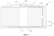
- FIG. 1 is Section View I of a button cell provided in Embodiment I of the present disclosure.
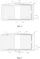
- FIG. 2 is Section View II of a button cell provided in Embodiment I of the present disclosure.
- FIG. 3 is Section View III of a button cell provided in Embodiment I of the present disclosure.
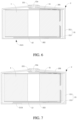
- FIG. 4 is Section View IV of a button cell provided in Embodiment I of the present disclosure.
- FIG. 5 is Section View V of the button cell provided in Embodiment I of the present disclosure.
- FIG. 6 is Section View VI of a button cell provided in Embodiment I of the present disclosure.
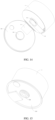
- FIG. 7 is Section View VII of a button cell provided in Embodiment I of the present disclosure. Referring to FIGS. 1 to 7 , the present embodiment provides a housing assembly of button cell.
- a housing assembly 2 of button cell includes a housing 21 and conductive parts.
- the housing 21 has a holding cavity that is capable of holding a cell 1 of the button cell.
- the cell 1 has a first tab 11 and a second tab 12.
- the housing 21 is provided with a through hole, and the conductive part is positioned at and blocks the through holes, and the conductive part and the through hole are set sealed and insulated, thereby a confined space can be formed inside the housing assembly 2 of the button cell.
- the conductive part may be a metal conductive part or a conductive part of other materials.
- the conductive part can be set as one or two, so that the design of the button cell can be more flexible.
- the housing is provided with only one through hole, and the conductive part is correspondingly positioned at and blocks the through hole.
- the conductive part may be configured to electrically connect with the first tab and the housing may be electrically connected with the second tab; or the conductive part may be configured o electrically connect with the second tab, and the housing may be electrically connected with the first tab. Therefore, electrical power generated on the cell can be output through the housing and the conductive part to provide electrical power for an external electrical equipment; or when the button cell is a rechargeable button cell and charged by an external charging equipment, the electrical power provided by the charging equipment to the button cell can be transmitted to the cell through the housing and the conductive part.
- the housing is provided with two through holes, and one of the conductive parts is correspondingly positioned at and blocks one of the through holes.
- One of the two conductive parts may be configured to electrically connect with the first tab, and the other one of the two conductive parts may be configured to electrically connect with the second tab. Therefore, the electrical power generated on the cell can be output through the two conductive parts to provide electrical power for an external electrical equipment; or when the button cell is a rechargeable button cell and charged by an external charging equipment, the electrical power provided by the charging equipment to the button cell can be transmitted to the cell through the two conductive parts.
- one of the first tab 11 and the second tab 12 is a positive electrode of the cell 1, and the other of the first tab 11 and the second tab 12 is a negative electrode of the cell 1.
- the conductive part is connected with a tab that serves as the positive electrode, and the housing 21 is connected to a tab that serves as the negative electrode.
- the button cell with the housing assembly 2 is applied to an electronic product, the conductive part is electrically connected to the positive electrode of the electronic product, and the housing 21 is electrically connected to the negative electrode of the electronic product, thereby supplying power to the electronic product.
- the number of the conductive part is two, one of the two conductive parts is connected with the tab that serves as the positive electrode, and the other of the two conductive parts is connected with the tab that serves as the negative electrode.
- the button cell with the housing assembly 2 is applied to an electronic product, the conductive part connected with the positive tab is electrically connected to the positive electrode of the electronic product, and the conductive part connected with the negative tab is electrically connected to the negative electrode of the electronic product, thereby supplying power to the electronic product.
- the housing assembly 2 of the button cell of the present embodiment includes the housing 21 and a conductive part.
- the housing 21 has a holding cavity that is capable of holding a cell 1 of the button cell, and the cell 1 has the first tab 11 and the second tab 12.
- this sealing method requires fewer sealing setting positions, it will not only make it easy to seal, but also have a relatively small risk of leakage after the sealing setting is completed. Therefore, this sealing method can make the housing assembly of button cell obtain a relatively good sealability, which is beneficial to improving quality and performance of the button cell.
- the conductive part can be set as one or two, so that the design of the button cell can be more flexible.
- the cell can output electrical power outward or input electrical power to the cell through the housing and the one conductive part; or, when the number of the conductive part is two, the housing is provided with the two through holes, and the conductive parts correspond to the through holes one by one, by electrically connecting one of the two conductive parts with the first tab, and electrically connecting the other one of the two conductive parts with the second tab, the cell can output electrical power outward or input electrical power to the cell through the two conductive parts.
- the housing of the present embodiment has two oppositely disposed end surfaces, and a specific implementation that at least one conductive part is located on the end surfaces includes:
- the holding cavity of the housing can be enlarged.
- a part of the conductive part located inside the through hole occupies the space defined by the convex surface, and then it can reduce or avoid the part of the conductive part located inside the through hole from occupying the columnar space where the cell is located.
- the space defined by the convex surface is the space swept by the end surface or a part of the end surface protruding from a flat surface state to form a convex surface.
- the conductive part when the number of the conductive part is one, the conductive part is located on the convex surface; when the number of the conductive part is two, one of the two conductive parts may be located on the convex surface, and the other conductive part is provided anywhere other than the convex surface according to actual needs, or the two conductive parts are located on the convex surface, thereby it can reduce or avoid a part of the conductive part located inside the through hole from occupying the columnar space where the cell is located, and then on the basis of improving the sealability of the housing assembly of button cell, it is beneficial to ensuring the performance of the button cell is not affected.
- first tab and / or at least a part of the second tab may also be provided in the space defined by the convex surface, thereby the first tab and / or the second tab do not need to occupy or occupy less the columnar space where the cell is located, and then it is beneficial to improve the performance of the button cell.
- a provision of the convex surface increases volumes of the holding cavity of the housing, thereby it is beneficial to increasing the amount of electrolyte injected into the holding cavity, and then improving the cycle performance of the button cell.
- At least a part of at least one end surface protrudes toward a direction away from the cell to form a convex surface.
- one of the two oppositely disposed sides of the housing 21 may be called an upper end surface 201, and the other may be called a lower end surface 202.
- the housing 21 of the present embodiment has an upper end surface 201 and a lower end surface 202 which are oppositely disposed.
- the upper end surface 201 may include two states: the first state is that the entire upper end surface 201 protrudes toward a direction away from the cell 1 to form a convex surface; the second state is that a part of the upper end surface 201 protrudes toward a direction away from the cell 1 to form a convex surface.
- the lower end surface 202 may include three states: the first state is that the entire lower end surface 202 protrudes toward a direction away from the cell 1 to form a convex surface; the second state is that a part of the lower end surface 202 protrudes toward a direction away from the cell 1 to form a convex surface; the third state is that the lower end surface 202 maintains a flat state.
- the upper end surface 201 of the housing 21 may be in any one of the two states, and the lower end surface 202 may be in any one of the three states, which can make the holding cavity of the housing 21 increase volumes of the space defined by the convex surface on the basis of an original volume.
- each of the two oppositely disposed end surfaces may be called an upper end surface, and the other is a lower end surface.
- the convex surface can be set as a spherical surface or a conical surface. On one hand, it is convenient for processing and molding; on the other hand, it is may make the shape of the button cell simple and elegant. In other embodiments, the convex surface may be separately provided according to actual needs. For example, it may be formed as a convex surface by splicing multiple flat surfaces. For another example, it may be formed as a convex surface by splicing together curved surfaces and flat surfaces.
- An implementation of the housing assembly 2 of the present embodiment is that the entire upper end surface 201 protrudes toward a direction away from the cell 1 to form a convex surface, the lower end surface 202 is a flat surface, and the number of the conductive part is one, and the conductive part is provided on the convex surface. Therefore, it can not only improve the sealability of the housing assembly of button cell, but also reduce or avoid the part of the conductive part located inside the through hole from occupying the columnar space where the cell is located, and then it is beneficial to improving the quality and performance of the button cell.
- an implementation of the housing assembly 2 of the button cell may also be that the entire upper end surface 201 protrudes toward a direction away from the cell 1 to form a convex surface, and the lower end surface 202 is a flat surface, and the number of the conductive part is one, and the conductive part may be set on the flat surface according to actual needs.
- the space defined by the convex surface can be used to set the tabs, and can be used to set other components located in the holding cavity of the housing, and can also be used to increase the amount of electrolyte injected. Therefore, it can improve the sealability of the housing assembly of button cell, and it is beneficial to improving the performance of the button cell.
- the conductive part in the present embodiment may be a conductive nail 22a penetrated in the through hole.
- the conductive nail 22a is provided with a sheet part or a flanging at both ends outside the through hole, thereby it is convenient for fixing the conductive nail 22a at the through hole.
- the following describes specific implementations of the conductive nail 22a set on the convex surface and the flat surface respectively.
- an end surface where a conductive nail 22a is located is a convex surface.
- the following describes in detail only by taking the convex surface as a spherical surface and a conical surface as an example. It can be understood that the convex surface may be other shapes than the spherical surface and the conical surface. When the convex surface is other shapes, specific arrangement methods of the conductive nail 22a can reference to arrangement methods on the spherical surface and the conical surface.
- the upper end surface 201 of the housing 21 protrudes in a direction away from the cell 1 to form a spherical surface
- the lower end surface 202 may be provided as a convex surface or a flat surface according to actual needs, and a flat surface is taken as an example here.
- the spherical surface is provided with a through hole.
- the through hole may be provided at the farthest end of the spherical surface protruding in a direction away from the cell 1, thereby an inside of the spherical surface has sufficient space for the conductive nail 22a, and then a part of the conductive nail 22a located inside the spherical surface will not interfere with the cell 1.
- an insulating part such as an insulating rubber ring 221 may be provided between the conductive nail 22a and the through hole.
- the insulating rubber ring 221 can not only insulate the conductive nail 22a from the housing 21, but also have an effect of sealing a gap between the conductive nail 22a and the housing 21.
- the first tab 11 may be directly connected with a part of the conductive nail 22a extended into the through hole, so that at least a part of the first tab 11 is located in the space defined by the spherical surface, thereby it will not to occupy the columnar space where the cell 1 is located.
- the second tab 12 may be directly connected with the other end surface of the housing 21, and the second tab 12 may also be electrically connected to any position of the housing 21 according to actual needs.
- the upper end surface 201 of the housing 21 protrudes in a direction away from the cell 1 to form a conical surface
- the lower end surface 202 may be provided with a convex surface or a flat surface according to actual needs, and a flat surface is taken as an example here.
- the conical surface is provided with a through hole.
- the through hole may be opened at the farthest end of the conical surface protruding in a direction away from the cell 1, i.e., the top of the tapered surface, thereby the inside of the tapered surface has sufficient space for the conductive nail 22a, and then the part of the conductive nail 22a located inside the tapered surface will not interfere with the cell 1.
- Other arrangement method in FIG. 2 can reference to the above description of FIG. 1 , which will not be repeated here.
- an end surface where a conductive nail 22a is located is a flat surface.
- the upper end surface 201 of the housing 21 protrudes in a direction away from the cell 1 to form a convex surface, and a spherical surface is taken as an example here.
- the lower end surface 202 is a flat surface, and a through hole is opened on the flat surface.
- the through hole is opened in the middle of the flat surface, and a part of the conductive nail 22a extended into the through hole can be set thinner to reduce the space occupied by the conductive nail 22a.
- an insulating part such as the insulating rubber ring 221, may be provided between the conductive nail 22a and the through hole.
- the insulating rubber ring 221 can not only insulate the conductive nail 22a and the housing 21, but also have an effect of sealing a gap between the conductive nail 22a and the housing 21.
- the second tab 12 may be directly connected with a part of the conductive nail 22a extended into the through hole.
- the first tab 11 may be extended into a space defined by the spherical surface and directly connected with the spherical surface. The space defined by the spherical surface may also be used to contain electrolyte to improve performance of the button cell.
- the first tab 11 and the second tab 12 may have another connection method, as shown in FIG. 4 , the holding cavity of the housing is further provided with a conductive pillar 13.
- the first tab 11 may be electrically connected with the conductive nail 22a through the conductive pillar 13 and the second tab 12 may be directly connected with the flat surface of the housing 21.
- the side of the conductive nail 22a away from the cell 1 is provided with a fabrication hole, thereby it is not only convenient for arranging the conductive nail on the housing, but also convenient for connecting external devices.
- an insulating part provided between the conductive nail 22a and the through hole may be an insulating rubber ring 221.
- a gasket 222 can also be provided on a part of the conductive nail 22a located outside the through hole, so that it makes the conductive nail 22a, the insulating rubber ring 221 and the through hole tighter and the sealability better.
- the conductive part in the present embodiment may also be a conductive sheet 22b provided inside the through hole.
- An insulating part 231 is provided between the conductive sheet 22b and the edge of the through hole.
- the position of the insulating part 231 corresponding to the outer edge of the conductive sheet 22b is provided with a groove into which the outer edge of the conductive sheet 22b can be extend.
- the conductive sheet 22b may be provided on a convex surface or a flat surface.
- the conductive sheet 22b is provided in a space defined by the convex surface.
- the upper end surface 201 of the housing 21 protrudes in a direction away from the cell 1 to form the spherical surface
- the lower end surface 202 may be provided with a convex surface or a flat surface according to actual needs, and a flat surface is taken as an example here.
- the spherical surface is provided with a through hole.
- the through hole may be provided at the farthest end of the spherical surface protruding in a direction away from the cell 1, thereby an inside of the spherical surface has sufficient space for the conductive sheet 22b, and then the conductive sheet 22b will not interfere with the cell 1.
- the insulating part 231 disposed between the conductive sheet 22b and the edge of the through hole may be an insulating rubber ring or an insulating part of other materials.
- the first tab 11 can extend into a space defined by the spherical surface and be electrically connected with the conductive sheet 22b, so that the first tab 11 does not occupy or occupies less columnar space where the cell 1 is located.
- the second tab 12 can be electrically connected with any position of the housing 21.
- the two conductive parts when the number of the conductive part is two, may be both conductive nails 22a penetrated in the through holes, or may be both conductive sheets 22b arranged inside the through holes, or may be one conductive nail 22a and one conductive sheets 22b.
- the specific arrangement of the two conductive parts can be adjusted adaptively with reference to the above arrangement methods of the conductive nail 22a and the conductive sheet 22b, which will not be repeated here.
- the housing of the present embodiment includes a first housing 211 and a second housing 212, where the first housing 211 and the second housing 212 enclose together to form the holding cavity, and the first housing 211 and the second housing 212 are integral parts.
- the first housing 211 may be a semi-enclosed structure with an opening at one end, or may be designed as a convex structure or a planar structure according to actual needs;
- the second housing 212 may be a planar structure or a convex structure, or may be designed as a structure with a bent part at the edge according to actual needs.
- the first housing 211 and the second housing 212 are integral parts, which means that the first housing 211 and the second housing 212 cannot be split.
- first housing 211 and the second housing 212 may be processed and molded at the same time into an inseparable whole, or after being processed separately, the first housing 211 and the second housing 212 may be joined by welding or other processes into an inseparable whole. Therefore, it can make the sealing effect of the housing assembly 2 of the button cell better, and reduce the risk of liquid leakage, and then it is beneficial to improving the quality and performance of the button cell.
- first housing 211 and the second housing 212 can also be set into a separable structure according to actual needs, which will not be repeated here.
- the first possible implementation is to set hardness of a conductive part to be smaller than hardness of a housing.
- the conductive part can be made of aluminum alloy. Therefore, in a process of gradually increasing the internal pressure of the housing assembly of button cell, the conductive part positioned at and blocking the through hole of the housing is first rushed to release the pressure, and thus prevent the internal pressure of the housing assembly of button cell from further increasing and eventually causing a serious explosion accident.
- the second possible implementation is to set thickness of the part of the conductive part located inside the through hole to be smaller than thickness of a housing wall. Therefore, on one hand, it is convenient for the housing assembly of button cell to rush the conductive part to release pressure during the increase of the internal pressure to prevent further explosion; on the other hand, it saves a space inside the housing assembly of button cell.
- the third possible implementation is to set at least a part of the housing wall of the housing 21 with a thinning area 2121, and thickness of the housing wall in the thinning area 2121 is smaller than thickness of other parts of the housing wall.
- the housing 21 includes the first housing 211 and the second housing 212.
- the thinning area 2121 may be an entire second housing 212 or a part of the second housing 212. As shown in FIG. 6 , thickness of the entire second housing 212 is smaller than thickness of the first housing 211, that is, the entire second housing 212 is a thinning area 2121. As shown in FIG.
- the part of the second housing 212 is set with the thinning area 2121, and the thickness of the thinning area 2121 is smaller than the thickness of other parts of the second housing 212.
- a shape of the thinning area 2121 may be any shape such as a circle, a square, or a cross. In other embodiments, the thinning area 2121 may also be an entire first housing 211 or a part of the first housing 211, which will not be repeated here.
- the thinning area in the process of gradually increasing the internal pressure of the housing assembly of button cell, the thinning area will first be unable to withstand the increasing pressure and be rushed to release the internal pressure of the housing assembly of button cell. Therefore, it can prevent the internal pressure of the housing assembly of button cell from further increasing and eventually causing a serious explosion accident.
- welding in the present embodiment may be laser welding, resistance welding, or ultrasonic welding according to the actual situation, and no specific limitation is made here.
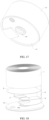
- FIG. 8 is Section View I of a button cell provided in Embodiment II of the present disclosure.
- FIG. 9 is a schematic structural view of a bottom cover of the button cell in FIG. 8 .
- FIG. 10 is Section View II of a button cell provided in Embodiment II of the present disclosure.
- FIG. 11 is a schematic structural view of a bottom cover of the button cell in FIG. 10 .
- FIG. 12 is a bottom view of the button cell provided in Embodiment II of the present disclosure after removing a second housing.
- FIG. 13 to FIG. 17 are schematic diagrams of an assembly process of the button cell provided in Embodiment II of the invention.
- FIG. 18 is an exploded view of a button cell provided in Embodiment II of the present disclosure. As shown in FIG. 8-18 , the present embodiment provides a housing assembly of button cell.
- the housing assembly 2 of the button cell in the present embodiment is the same as that in Embodiment I, including a housing 21 and conductive parts.
- the housing 21 of the present embodiment includes a first housing 211 having an opening at one end and a second housing 212 covered at the opening of the first housing 211.
- the second housing 212 may also be called a bottom cover.
- a side of the second housing 212 facing the first housing 211 is provided with a boss 2122 matching the opening of the first housing 211.
- the boss 2122 may be formed by the second housing 212 protruding toward the first housing 211, or may be a boss structure added on a side of the second housing 212 facing the first housing 211.
- the boss 2122 on the second housing 212 extends into the first housing 211. Therefore, it is not only convenient for welding the first housing 211 and the second housing 212 together to make the joint between the first housing 211 and the second housing 212 more reliable, but also further improves sealability of the housing.
- the conductive part in the present embodiment is a conductive nail 22a provided on the second housing 212.
- the conductive nail 22a is located at the center of the second housing 212, that is, the center of the second housing 212 is provided with a through hole 2124, and the conductive nail 22a is penetrated through the through hole 2124, and at the same time, an insulating part is provided between the conductive nail 22a and the through hole 2124.
- the conductive nail 22a includes a columnar part 22a2 and a sheet part 22a1 extending from the side of the second housing 212 which have the boss 2122. Thickness of the sheet part 22a1 can be set according to actual needs.
- the thickness of the sheet part 22a1 can be set between 0.1 mm and 0.25 mm and, in an implementation, between 0.12 mm and 0.2 mm.
- One end of the columnar part 22a2 may be connected with the sheet part 22a1 by welding, and the other end of the columnar part 22a2 is provided with a flanging 22a3 extending toward the periphery of the through hole 2124.
- a width of the flanging 22a3 can be set according to actual needs.
- the width of the flanging 22a3 can be set between 0.3mm and 2.5mm and thus, on the one hand, the conductive nail 22a can be fixed on the second housing 212, and on the other hand, it is convenient for tightly compressing the insulating part provided between the conductive nail 22a and the through hole 2124.
- the sheet part 22a1 and the columnar part 22a2 may be separately processed and connected by welding or the like, or may be integrally formed.
- the insulating part may be an insulating rubber ring 221, and the insulating rubber ring 221 may be made of fluorine rubber or EPDM rubber, or may be made of other materials.
- a gasket 222 can also be provided between the flanging 22a3 of the conductive nail 22a and the insulating rubber ring 221.
- the gasket 222 may be a stainless-steel gasket or a nickel alloy gasket, or may be a gasket of other materials.
- a fabrication hole 22a4 for welding may be opened in the columnar part 22a2 of the conductive nail.
- a welding gun can extend from the fabrication hole 22a4 into the inside of the conductive nail 22a to weld the sheet part 22a1 of the conductive nail and the second tab 12 together.
- the boss 2122 of the second housing of the present embodiment may be provided with a tab groove 2123 for receiving a tab, and the shape of the tab groove 2123 may match the shape of the tab provided therein. Therefore, on the one hand, the tabs provided therein can be positioned, and on the other hand, the tabs provided therein do not occupy or occupy less space where a cell is located.
- the tab groove 2123 may be formed by depressing the surface of the boss 2122 toward a direction away from a first housing 211, or by removing a part of material on the surface of the boss 2122. In an implementation, as shown in FIG. 8 and FIG.
- a flat surface of a groove bottom of the tab groove 2123 is located between an upper surface of the boss 2122 and a flat surface of a lower edge of the boss 2122. Therefore, on the one hand, it is capable of holding and positioning the tabs to save an internal space of the button cell; on the other hand, it is convenient for welding the first housing 211 and the second housing 212 to improve reliability and sealability of a joint between the first housing 211 and the second housing 212.
- the flat surface of the groove bottom of the tab groove 2123 can also be flush with the plane of the lower edge of the boss 2122, thereby it may make a holding space inside the tab groove 2123 larger. It can not only avoid the tab from occupying the space where the cell is located, but also may increase a capacity of the button cell to accommodate electrolyte, and then is beneficial to improving performance of the button cell.
- the housing 21 of the present embodiment is also provided with an injection port 2125.
- the injection port 2125 is configured to inject electrolyte into the button cell.
- the injection port 2125 may be provided on the first housing 211 according to actual needs, or may be provided on the second housing 212 (as shown in FIGS. 8 to 18 ), no specific limitation is made here.
- the first tab 11 may be connected with the tab groove 2123 of the second housing 212, and the second tab 12 is connected with the sheet part 22a1 of the conductive nail.
- a position where the second tab 12 is connected with the sheet part 22a1 may be depressed in a direction away from the sheet part 22a1 to form a conductive groove 121 matching the shape of the sheet part 22a1.
- the sheet part 22a1 is circular
- the position where the second tab 12 is connected with the sheet part 22a1 may be depressed to form a circular conductive groove 121.
- the second tab 12 can be snap-fitted on the sheet part 22a1 to achieve a positioning connection with the second tab 12. Furthermore, as shown in FIG. 12 , in order to prevent a short-circuit between the first tab 11 and the second tab 12, the included angle between an orthographic projection of the first tab 11 on the second housing 212 and an orthographic projection of the second tab 12 on the second housing 212 can be set between 20° and 160°. In addition, as shown in FIG. 8 and FIG.
- a cross-sectional shape of a cavity 14 in the middle of the cell can be provided to match a cross-sectional shape of the sheet part 22a1 of the conductive nail, so that when the conductive nail 22a is assembled, the sheet part 22a1 of the conductive nail can extend into the cavity 14 in the middle of the cell.
- the cross section of the sheet part 22a1 of the conductive nail may be circular, and the cross section of the cavity 14 in the middle of the cell may be circular too, and the diameter of the circular cross section of the cavity 14 in the middle of the cell is larger than the diameter of the circular cross section of the sheet part 22a1 of the conductive nail, so that the sheet part 22a1 of the conductive nail can be smoothly extended into the cavity 14 in the middle of the cell.
- a part of the conductive groove 121 where the second tab 12 is snap-fitted on the sheet part 22a1 of the conductive nail may also extend into the cavity 14 in the middle of the cell along with the sheet part 22a1.
- an insulating part between the sheet part 22a1 of the conductive nail and the second housing 212 may also partially or fully extend into the cavity 14 in the middle of the cell. Therefore, the sheet part 22a1 of the conductive nail and the insulating part provided between the sheet part 22a1 of the conductive nail and the second housing 212 do not occupy or less occupy the thickness of the space where the cell is located.
- FIGS. 13 to 17 The specific assembly process of the button cell with the housing assembly of the present embodiment is shown in FIGS. 13 to 17 .
- the welding gun extends from the fabrication hole 22a4 into the conductive nail 22a, and conducts welding from a side of the sheet part 22a1 located in the fabrication hole 22a4 to weld the sheet part 22a1 of the conductive nail and the second tab 12 together.
- the first housing 211 on the outside of the cell 1 and weld the first housing 211 and the second housing 212 together to complete the assembly of button cell, as shown in FIG.
- the assembled button cell needs to be injected with electrolyte through an injection port, and then several processes such as chemical conversion treatment and exhaust treatment need to be performed and finally, the injection port is sealed, for example, a metal cover can be welded at the injection port to complete the sealing.
- a first insulating sheet 31 may be interposed between the second tab 12 and the second housing 212.
- the first insulating sheet 31 is an insulating rubber sheet.
- the first insulating sheet 31 may also be an insulating sheet of other materials.
- the first insulating sheet 31 is provided with a clearance area for avoiding the sheet part 22a1 of the conductive nail, so that the second tab 12 and the sheet part 22a1 of the conductive nail can be smoothly connected and conducted.
- the cross section of the sheet part 22a1 of the conductive nail is circular
- the clearance area of the sheet part 22a1 on the first insulating sheet 31 is a circular hole matching the cross-sectional size of the sheet part, so that the first insulating sheet 31 can be sheathed around the periphery of the sheet part 22a1.
- the first insulating sheet 31 should also be provided with a clearance area for avoiding the injection port 2125, so as to prevent the first insulating sheet 31 from affecting the process of injecting the electrolyte into the button cell.
- the first insulating sheet 31 may have a fan shape or other shapes, as long as it can be interposed between the second tab 12 and the second housing 212 to realize the function of insulation.
- a shape of the first insulating sheet 31 may avoid the tab groove 2123 of the second housing 212, and may also cover the tab groove 2123 of the second housing 212, so that the first tab 11 and the second tab 12 are located on two sides of the first insulating sheet 31, improving the insulation ability between the first tab 11 and the second tab 12.
- a second insulating sheet 32 may also be clamped between the cell 1 and the second tab 12.
- the second insulating sheet 32 is an insulating rubber sheet.
- the second insulating sheet 32 may also be an insulating sheet of other materials.
- the second insulating sheet 32 is provided with a clearance area for avoiding the first tab 11 and the second tab 12, and thus it does not hinder the first tab 11 and the second tab 12 connecting and conducting with the housing assembly 2.
- the second insulating sheet 32 may have a circular shape with a cut surface or other shapes, as long as it can be clamped between the cell 1 and the second tab 12 to realize the function of insulation.
- the present embodiment provides a button cell, including a cell and a housing assembly of button cell.
- the housing assembly of button cell in the present embodiment has a same structure as the housing assembly of button cell provided in Embodiment I, and can bring same or similar technical effects, which will not be repeated here one by one.
- the present embodiment provides an electronic product, including a button cell.
- the button cell in the present embodiment has a same structure as the button cell provided in Embodiment II, and can bring same or similar technical effects, which will not be repeated here one by one.
- top In the description of the present disclosure, it should be understood that the terms “top”, “bottom”, “upper”, “lower” (if present), etc. indicate the orientation or positional relationship based on the orientation or positional relationship shown in the drawings It is only for the convenience of describing the present disclosure and simplifying the description, but not for indicating or implying that apparatus or elements referred to must have a specific orientation, and be constructed and operated in a specific orientation, therefore, it cannot be understood as limiting the present disclosure.
- connection should be understood broadly.
- it can be a fixed connection, a detachable connection, or an integrally connection; it can be a mechanically connection or an electrically connection; it can be a directly connection, or an indirectly connection through an intermediary, or an internally connection between two components.
- connection should be understood broadly.
- it can be a fixed connection, a detachable connection, or an integrally connection; it can be a mechanically connection or an electrically connection; it can be a directly connection, or an indirectly connection through an intermediary, or an internally connection between two components.
Landscapes
- Chemical & Material Sciences (AREA)
- Chemical Kinetics & Catalysis (AREA)
- Electrochemistry (AREA)
- General Chemical & Material Sciences (AREA)
- Battery Mounting, Suspending (AREA)
- Sealing Battery Cases Or Jackets (AREA)
- Connection Of Batteries Or Terminals (AREA)
Applications Claiming Priority (2)
| Application Number | Priority Date | Filing Date | Title |
|---|---|---|---|
| CN202010140708 | 2020-03-03 | ||
| EP20185501.2A EP3876338B1 (de) | 2020-03-03 | 2020-07-13 | Gehäuseanordnung einer knopfzelle, knopfzelle und elektronisches produkt |
Related Parent Applications (2)
| Application Number | Title | Priority Date | Filing Date |
|---|---|---|---|
| EP20185501.2A Division-Into EP3876338B1 (de) | 2020-03-03 | 2020-07-13 | Gehäuseanordnung einer knopfzelle, knopfzelle und elektronisches produkt |
| EP20185501.2A Division EP3876338B1 (de) | 2020-03-03 | 2020-07-13 | Gehäuseanordnung einer knopfzelle, knopfzelle und elektronisches produkt |
Publications (2)
| Publication Number | Publication Date |
|---|---|
| EP4421972A2 true EP4421972A2 (de) | 2024-08-28 |
| EP4421972A3 EP4421972A3 (de) | 2025-03-26 |
Family
ID=71553227
Family Applications (3)
| Application Number | Title | Priority Date | Filing Date |
|---|---|---|---|
| EP24187599.6A Pending EP4421972A3 (de) | 2020-03-03 | 2020-07-13 | Gehäuseanordnung einer knopfzelle, knopfzelle und elektronisches produkt |
| EP24187600.2A Pending EP4425688A3 (de) | 2020-03-03 | 2020-07-13 | Gehäuseanordnung einer knopfzelle, knopfzelle und elektronisches produkt |
| EP20185501.2A Active EP3876338B1 (de) | 2020-03-03 | 2020-07-13 | Gehäuseanordnung einer knopfzelle, knopfzelle und elektronisches produkt |
Family Applications After (2)
| Application Number | Title | Priority Date | Filing Date |
|---|---|---|---|
| EP24187600.2A Pending EP4425688A3 (de) | 2020-03-03 | 2020-07-13 | Gehäuseanordnung einer knopfzelle, knopfzelle und elektronisches produkt |
| EP20185501.2A Active EP3876338B1 (de) | 2020-03-03 | 2020-07-13 | Gehäuseanordnung einer knopfzelle, knopfzelle und elektronisches produkt |
Country Status (3)
| Country | Link |
|---|---|
| US (3) | US12107286B2 (de) |
| EP (3) | EP4421972A3 (de) |
| CN (3) | CN211907486U (de) |
Families Citing this family (49)
| Publication number | Priority date | Publication date | Assignee | Title |
|---|---|---|---|---|
| KR102471745B1 (ko) | 2020-02-03 | 2022-11-25 | 삼성에스디아이 주식회사 | 이차 전지 |
| CN112002834A (zh) * | 2020-06-12 | 2020-11-27 | 珠海市讯达科技有限公司 | 一种纽扣电池及其制作方法 |
| US20210399389A1 (en) * | 2020-06-22 | 2021-12-23 | Samsung Sdi Co., Ltd. | Rechargeable battery |
| CN111900275A (zh) * | 2020-08-04 | 2020-11-06 | 珠海冠宇电池股份有限公司 | 扣式电池及其制备方法 |
| WO2022059337A1 (ja) * | 2020-09-17 | 2022-03-24 | 株式会社村田製作所 | 二次電池 |
| WO2022060136A1 (ko) | 2020-09-18 | 2022-03-24 | 주식회사 엘지에너지솔루션 | 버튼형 이차전지 |
| CN112290131A (zh) * | 2020-11-18 | 2021-01-29 | 江门市元熙科技有限公司 | 一种扣式电池 |
| CN213816269U (zh) * | 2020-12-21 | 2021-07-27 | 珠海冠宇电池股份有限公司 | 电池 |
| CA3202317A1 (en) * | 2021-01-19 | 2022-07-28 | Lg Energy Solution, Ltd. | Battery and current collector applied thereto, and battery pack and vehicle including the same |
| US20240063423A1 (en) * | 2021-01-19 | 2024-02-22 | Lg Energy Solution, Ltd. | Sub cell and its manufacturing method, and cylindrical secondary battery, battery pack and vehicle comprising the sub cell |
| US12132227B2 (en) | 2021-01-19 | 2024-10-29 | Lg Energy Solution, Ltd. | Battery, and battery pack and vehicle comprising the same |
| US12407028B2 (en) | 2021-02-19 | 2025-09-02 | Lg Energy Solution, Ltd. | Electrode assembly, battery, and battery pack and vehicle including the same |
| CA3207443A1 (en) * | 2021-02-19 | 2022-08-25 | Min-Woo Kim | Electrode assembly, battery, and battery pack and vehicle including the same |
| JP7721647B2 (ja) * | 2021-02-19 | 2025-08-12 | エルジー エナジー ソリューション リミテッド | バッテリー、それを含むバッテリーパック及び自動車 |
| JP7617267B2 (ja) * | 2021-02-23 | 2025-01-17 | エルジー エナジー ソリューション リミテッド | 二次電池、電池パック、および自動車 |
| WO2022198676A1 (zh) * | 2021-03-26 | 2022-09-29 | 宁德新能源科技有限公司 | 极柱、电池及电子设备 |
| CN113270671B (zh) * | 2021-05-13 | 2024-04-16 | 宁德新能源科技有限公司 | 电芯及用电装置 |
| KR102688976B1 (ko) * | 2021-05-14 | 2024-07-29 | 삼성에스디아이 주식회사 | 이차 전지 |
| CN113328198B (zh) * | 2021-05-27 | 2025-06-27 | 宁德新能源科技有限公司 | 电池及用电装置 |
| DE102021113874A1 (de) | 2021-05-28 | 2022-12-01 | Bayerische Motoren Werke Aktiengesellschaft | Zellgehäuse für eine Batteriezelle, eine Batteriezelle und ein Verfahren zur Herstellung einer Batteriezelle |
| WO2023004713A1 (zh) * | 2021-07-29 | 2023-02-02 | 珠海微矩实业有限公司 | 微型电池 |
| CN113745713A (zh) * | 2021-07-29 | 2021-12-03 | 珠海微矩实业有限公司 | 微型电池 |
| CN113437350B (zh) * | 2021-07-29 | 2025-07-01 | 珠海冠宇电池股份有限公司 | 电池 |
| CN215342693U (zh) * | 2021-07-30 | 2021-12-28 | 珠海冠宇电池股份有限公司 | 一种电池及电子产品 |
| CN113346166B (zh) * | 2021-08-06 | 2021-10-29 | 国研新能(深圳)技术有限公司 | 纽扣电池组件和电子设备 |
| CN113471513A (zh) * | 2021-08-09 | 2021-10-01 | 东莞市电的电子有限公司 | 一种微型锂电池及其制备方法 |
| WO2023025104A1 (zh) * | 2021-08-23 | 2023-03-02 | 宁德时代新能源科技股份有限公司 | 电池单体、电池以及用电装置 |
| JP7481497B2 (ja) | 2021-08-23 | 2024-05-10 | 寧徳時代新能源科技股▲分▼有限公司 | 電池セル、その製造方法及び製造システム、電池並びに電力消費装置 |
| JP7512426B2 (ja) | 2021-08-23 | 2024-07-08 | 寧徳時代新能源科技股▲分▼有限公司 | 電池セル、その製造方法及び製造システム、電池並びに電力消費装置 |
| CN215911481U (zh) * | 2021-08-31 | 2022-02-25 | 广东微电新能源有限公司 | 储能装置及电子设备 |
| CN113937395B (zh) * | 2021-09-30 | 2024-10-22 | 新余赣锋电子有限公司 | 一种扣式电池 |
| HUE071772T2 (hu) | 2021-10-14 | 2025-09-28 | Lg Energy Solution Ltd | Akkumulátor, az arra alkalmazott áramgyûjtõ lemez, valamint az azt tartalmazó akkumulátorcsomag és jármû |
| CN116014313A (zh) * | 2021-10-22 | 2023-04-25 | 株式会社Lg新能源 | 圆筒形电池、包括它的电池组及汽车 |
| CN113972449B (zh) * | 2021-10-25 | 2024-01-30 | 珠海冠宇电池股份有限公司 | 一种电池及电子产品 |
| JP7762802B2 (ja) * | 2021-10-29 | 2025-10-30 | 寧徳新能源科技有限公司 | 電気化学装置及び電気デバイス |
| EP4325637A4 (de) * | 2021-11-19 | 2024-10-16 | LG Energy Solution, Ltd. | Sekundärbatterie und batteriepack sowie fahrzeug damit |
| CN114204221B (zh) * | 2021-12-02 | 2024-12-10 | 宁德新能源科技有限公司 | 一种电化学装置、电池模组及电子装置 |
| CN114069019B (zh) * | 2021-12-08 | 2025-03-18 | 深圳聚锂能源有限公司 | 一种扣式电池壳体、扣式电池及组装方法 |
| CN114069115A (zh) * | 2021-12-14 | 2022-02-18 | 深圳市合壹新能技术有限公司 | 纽扣电池 |
| KR102794895B1 (ko) * | 2022-01-19 | 2025-04-14 | 삼성에스디아이 주식회사 | 이차 전지 |
| US20250219267A1 (en) * | 2022-03-08 | 2025-07-03 | Lg Energy Solution, Ltd. | Cylindrical battery cell, and battery pack and vehicle including the same |
| CN115084796B (zh) * | 2022-06-14 | 2025-02-11 | 东莞锂威能源科技有限公司 | 一种导针复合扣式电池 |
| CN116438706A (zh) * | 2022-06-21 | 2023-07-14 | 宁德新能源科技有限公司 | 扣式电池及电子装置 |
| WO2024014939A1 (ko) * | 2022-07-15 | 2024-01-18 | 주식회사 엘지에너지솔루션 | 원통형 배터리 셀 및 이를 포함하는 배터리 팩 및 자동차 |
| KR102858737B1 (ko) * | 2022-07-21 | 2025-09-12 | 주식회사 엘지에너지솔루션 | 전극 단자의 고정 구조 및 이를 포함하는 배터리, 배터리 팩 및 자동차 |
| EP4456270A1 (de) * | 2023-04-26 | 2024-10-30 | VARTA Microbattery GmbH | Elektrochemisches energiespeicherelement |
| EP4539179A1 (de) * | 2023-10-11 | 2025-04-16 | VARTA Microbattery GmbH | Elektrochemisches energiespeicherelement, insbesondere in form einer miniaturzelle |
| WO2025100878A1 (ko) * | 2023-11-07 | 2025-05-15 | 주식회사 엘지에너지솔루션 | 이차전지의 전극집전판 및 이를 적용한 원통형 이차전지 |
| CN223285090U (zh) * | 2024-09-24 | 2025-08-29 | 惠州亿纬锂能股份有限公司 | 盖板组件、微型电池及胶囊内窥镜 |
Family Cites Families (29)
| Publication number | Priority date | Publication date | Assignee | Title |
|---|---|---|---|---|
| JP2000011981A (ja) * | 1998-06-25 | 2000-01-14 | Shin Kobe Electric Mach Co Ltd | 非水電解質二次電池 |
| JP2002175789A (ja) * | 2000-12-06 | 2002-06-21 | Matsushita Electric Ind Co Ltd | 偏平形電池とその製造方法 |
| CN1331249C (zh) * | 2002-12-25 | 2007-08-08 | 富士重工业株式会社 | 蓄电装置 |
| CN2833901Y (zh) * | 2005-08-19 | 2006-11-01 | 周基平 | 圆柱形锂电池 |
| JP2008262825A (ja) * | 2007-04-12 | 2008-10-30 | Hitachi Maxell Ltd | コイン形非水電解液二次電池 |
| KR100962397B1 (ko) * | 2007-11-28 | 2010-06-11 | 주식회사 이엠따블유에너지 | 전지 및 그 제조방법 |
| US11081721B2 (en) * | 2009-11-24 | 2021-08-03 | Duracell U.S. Operations, Inc. | Secondary electrochemical cells with separator and electrolyte combination |
| KR101093932B1 (ko) * | 2010-01-26 | 2011-12-13 | 에스비리모티브 주식회사 | 이차 전지 |
| CN202434592U (zh) * | 2012-01-18 | 2012-09-12 | 蚌埠市立群电子有限公司 | 一次扣式锂电池用玻璃密封盖组 |
| DE102012214443A1 (de) * | 2012-08-14 | 2014-02-20 | Robert Bosch Gmbh | Verspannen von Batteriezellen durch eine bombierte Ausgestaltung des Batteriegehäuses |
| CN104919617A (zh) * | 2012-11-09 | 2015-09-16 | 瓦尔达微电池有限责任公司 | 具有电极线圈的纽扣电池 |
| CN104838528B (zh) * | 2012-11-19 | 2017-10-27 | 松下知识产权经营株式会社 | 扁平形电池 |
| CN103500844B (zh) * | 2013-09-03 | 2016-09-14 | 浙江金开来新能源科技有限公司 | 圆柱形多极耳锂离子电池及其制备方法 |
| CN203553232U (zh) * | 2013-09-11 | 2014-04-16 | 力佳电源科技(深圳)有限公司 | 一种新型扣式电池 |
| CN104393204B (zh) * | 2014-11-12 | 2016-10-05 | 浙江悦达塑业股份有限公司 | 一种蓄电池中盖结构 |
| JP2016103447A (ja) * | 2014-11-28 | 2016-06-02 | 株式会社豊田自動織機 | 蓄電装置 |
| CN105990557B (zh) * | 2015-02-17 | 2019-09-27 | 江西金路新能源有限公司 | 一种锂电池连接方法及其连接装置 |
| CN106159350B (zh) * | 2015-04-27 | 2019-04-26 | 深圳金山电池有限公司 | 一种纽扣型锂离子二次电池及其制备方法 |
| CN105958109B (zh) * | 2016-06-08 | 2019-02-01 | 惠州亿纬锂能股份有限公司 | 一种可充电硬壳锂离子电池 |
| CN106601960B (zh) * | 2016-12-30 | 2023-10-13 | 重庆市紫建电子有限公司 | 一种纽扣电池及其制造方法 |
| CN106601942A (zh) * | 2017-02-09 | 2017-04-26 | 重庆市紫建电子有限公司 | 一种柱型电池及其用途 |
| CN108428813A (zh) * | 2017-02-15 | 2018-08-21 | 宁德新能源科技有限公司 | 软包电池 |
| CN106936190A (zh) * | 2017-04-18 | 2017-07-07 | 丁军浩 | 电池组、供电装置及充电装置 |
| CN208819925U (zh) * | 2018-09-19 | 2019-05-03 | 宁德时代新能源科技股份有限公司 | 顶盖组件以及二次电池 |
| CN109786611B (zh) * | 2019-02-02 | 2024-01-16 | 广东微电新能源有限公司 | 电池装置以及电子设备 |
| CN209804717U (zh) * | 2019-03-07 | 2019-12-17 | 广东微电新能源有限公司 | 一种纽扣电池 |
| CN110048137B (zh) * | 2019-05-21 | 2024-05-21 | 宜昌力佳科技有限公司 | 扣式电池及扣式电池的制备方法 |
| CN110459705A (zh) * | 2019-09-05 | 2019-11-15 | 重庆市紫建电子有限公司 | 一种提升径向空间利用率的纽扣电池 |
| CN110828885A (zh) * | 2019-11-11 | 2020-02-21 | 中山市众旺德新能源科技有限公司 | 一种扣式柱状锂离子电池及制造方法 |
-
2020
- 2020-05-25 CN CN202020901291.2U patent/CN211907486U/zh not_active Ceased
- 2020-05-25 CN CN202010448318.1A patent/CN111446386B/zh active Active
- 2020-05-25 CN CN202010447734.XA patent/CN111430588B/zh active Active
- 2020-07-13 EP EP24187599.6A patent/EP4421972A3/de active Pending
- 2020-07-13 EP EP24187600.2A patent/EP4425688A3/de active Pending
- 2020-07-13 EP EP20185501.2A patent/EP3876338B1/de active Active
- 2020-07-16 US US16/930,361 patent/US12107286B2/en active Active
-
2024
- 2024-09-05 US US18/825,495 patent/US20240429511A1/en active Pending
- 2024-09-05 US US18/825,372 patent/US20240429510A1/en active Pending
Also Published As
| Publication number | Publication date |
|---|---|
| CN111430588A (zh) | 2020-07-17 |
| EP3876338C0 (de) | 2024-08-21 |
| US20210280835A1 (en) | 2021-09-09 |
| US20240429511A1 (en) | 2024-12-26 |
| EP3876338B1 (de) | 2024-08-21 |
| EP3876338A1 (de) | 2021-09-08 |
| CN111430588B (zh) | 2023-08-22 |
| CN211907486U (zh) | 2020-11-10 |
| EP4425688A3 (de) | 2025-03-26 |
| CN111446386B (zh) | 2024-10-22 |
| CN111446386A (zh) | 2020-07-24 |
| US12107286B2 (en) | 2024-10-01 |
| EP4421972A3 (de) | 2025-03-26 |
| EP4425688A2 (de) | 2024-09-04 |
| US20240429510A1 (en) | 2024-12-26 |
Similar Documents
| Publication | Publication Date | Title |
|---|---|---|
| US20240429510A1 (en) | Housing assembly of button cell, button cell and electronic product | |
| EP4050708A1 (de) | Knopfbatterie und herstellungsverfahren dafür | |
| US9515297B2 (en) | Rechargeable battery | |
| CN211404538U (zh) | 扣式电池的外壳组件、扣式电池以及电子产品 | |
| KR102246736B1 (ko) | 이차 전지 | |
| EP4333168B1 (de) | Batterie und elektronisches produkt | |
| US20150147637A1 (en) | Electric connector and battery comprising the same | |
| KR20210021841A (ko) | 이차 전지 | |
| JP5866621B2 (ja) | 蓋体、密閉型電池、および密閉型電池の製造方法 | |
| CN211654872U (zh) | 扣式电池的外壳组件、扣式电池以及电子产品 | |
| WO2022228091A1 (zh) | 锂电池及其制备方法 | |
| JP2009087613A (ja) | 角型電池 | |
| CN211654873U (zh) | 扣式电池的外壳组件、扣式电池以及电子产品 | |
| CN218242010U (zh) | 一种电池 | |
| CN216563438U (zh) | 电池 | |
| JP2022544426A (ja) | 電池およびそれを備えた電気機器 | |
| CN211404539U (zh) | 扣式电池的外壳组件、扣式电池以及电子产品 | |
| CN219203440U (zh) | 一种圆柱电池及电子设备 | |
| CN218101611U (zh) | 电池和电子设备 | |
| CN118970308B (zh) | 电芯及电池包 | |
| CN218005043U (zh) | 一种扣式电池 | |
| CN216872213U (zh) | 极柱组件、电池及电子装置 | |
| CN217903272U (zh) | 方形电池以及电子设备 | |
| KR102961744B1 (ko) | 배터리 및 전자제품 | |
| JP2023182432A (ja) | 蓄電素子 |
Legal Events
| Date | Code | Title | Description |
|---|---|---|---|
| PUAI | Public reference made under article 153(3) epc to a published international application that has entered the european phase |
Free format text: ORIGINAL CODE: 0009012 |
|
| STAA | Information on the status of an ep patent application or granted ep patent |
Free format text: STATUS: REQUEST FOR EXAMINATION WAS MADE |
|
| 17P | Request for examination filed |
Effective date: 20240710 |
|
| AC | Divisional application: reference to earlier application |
Ref document number: 3876338 Country of ref document: EP Kind code of ref document: P |
|
| AK | Designated contracting states |
Kind code of ref document: A2 Designated state(s): AL AT BE BG CH CY CZ DE DK EE ES FI FR GB GR HR HU IE IS IT LI LT LU LV MC MK MT NL NO PL PT RO RS SE SI SK SM TR |
|
| REG | Reference to a national code |
Ref country code: DE Ref legal event code: R079 Free format text: PREVIOUS MAIN CLASS: H01M0050538000 Ipc: H01M0050109000 |
|
| PUAL | Search report despatched |
Free format text: ORIGINAL CODE: 0009013 |
|
| AK | Designated contracting states |
Kind code of ref document: A3 Designated state(s): AL AT BE BG CH CY CZ DE DK EE ES FI FR GB GR HR HU IE IS IT LI LT LU LV MC MK MT NL NO PL PT RO RS SE SI SK SM TR |
|
| RIC1 | Information provided on ipc code assigned before grant |
Ipc: H01M 50/538 20210101ALI20250214BHEP Ipc: H01M 50/172 20210101ALI20250214BHEP Ipc: H01M 50/183 20210101ALI20250214BHEP Ipc: H01M 50/109 20210101AFI20250214BHEP |