EP4420847B1 - Produktfördervorrichtung mit traktionsrolle - Google Patents
Produktfördervorrichtung mit traktionsrolle Download PDFInfo
- Publication number
- EP4420847B1 EP4420847B1 EP23157945.9A EP23157945A EP4420847B1 EP 4420847 B1 EP4420847 B1 EP 4420847B1 EP 23157945 A EP23157945 A EP 23157945A EP 4420847 B1 EP4420847 B1 EP 4420847B1
- Authority
- EP
- European Patent Office
- Prior art keywords
- product
- traction
- conveying
- traction roller
- food
- Prior art date
- Legal status (The legal status is an assumption and is not a legal conclusion. Google has not performed a legal analysis and makes no representation as to the accuracy of the status listed.)
- Active
Links
Images


Classifications
-
- B—PERFORMING OPERATIONS; TRANSPORTING
- B26—HAND CUTTING TOOLS; CUTTING; SEVERING
- B26D—CUTTING; DETAILS COMMON TO MACHINES FOR PERFORATING, PUNCHING, CUTTING-OUT, STAMPING-OUT OR SEVERING
- B26D7/00—Details of apparatus for cutting, cutting-out, stamping-out, punching, perforating, or severing by means other than cutting
- B26D7/06—Arrangements for feeding or delivering work of other than sheet, web, or filamentary form
- B26D7/0625—Arrangements for feeding or delivering work of other than sheet, web, or filamentary form by endless conveyors, e.g. belts
-
- B—PERFORMING OPERATIONS; TRANSPORTING
- B26—HAND CUTTING TOOLS; CUTTING; SEVERING
- B26D—CUTTING; DETAILS COMMON TO MACHINES FOR PERFORATING, PUNCHING, CUTTING-OUT, STAMPING-OUT OR SEVERING
- B26D7/00—Details of apparatus for cutting, cutting-out, stamping-out, punching, perforating, or severing by means other than cutting
- B26D7/06—Arrangements for feeding or delivering work of other than sheet, web, or filamentary form
-
- B—PERFORMING OPERATIONS; TRANSPORTING
- B26—HAND CUTTING TOOLS; CUTTING; SEVERING
- B26D—CUTTING; DETAILS COMMON TO MACHINES FOR PERFORATING, PUNCHING, CUTTING-OUT, STAMPING-OUT OR SEVERING
- B26D2210/00—Machines or methods used for cutting special materials
- B26D2210/02—Machines or methods used for cutting special materials for cutting food products, e.g. food slicers
Definitions
- the present invention relates to a product conveying device for feeding food products to a slicing unit of a food slicing machine, a food slicing machine, a method for removing a cassette from a food slicing machine, and the use of a traction roller to feed a food product to a slicing unit.
- Food products such as sausage, cheese, or bread
- a food slicing machine which may be a high-performance slicer, into a slicing unit with a cutting blade, for example, a rotating sickle or circular blade.
- one or more product conveying devices are provided in a feeding area, which are in contact with the food bar in order to move it to a cutting plane of the slicing unit.
- the product conveying device can be designed as a lower product support, on which the food bar rests, or as an upper product hold-down device, which presses down on the food bar from above, or both together, see, for example, the US 2015/321372 .
- the known variants for driving the tracks of a product conveyor device are technically complex or have disadvantages with regard to the mechanical bearing.
- the object of the invention is to provide an alternative multi-lane product conveying device.
- a food slicing machine particularly a high-performance slicer
- one or more food products can be sliced into food slices by means of a slicing unit.
- the slicing unit can comprise a rotary and/or planetary cutting blade, particularly a sickle or circular blade.
- a food product can initially be placed on a single-feed conveyor, or placed or conveyed onto it.
- a track guide with center dividers, particularly metal sheets, can be mounted above the single-feed conveyor. These dividers extend from the top to just above the surface of the single-feed conveyor. The lateral position of these center dividers can be adjusted to the width of the food product to be sliced. From the single-feed conveyor, the food product can be conveyed onto a product conveyor.
- the product conveyor belt following the infeed belt in the conveying direction can be part of a loading swing arm and can be pivoted upwards about an axis located on its downstream side. This allows the food product to be conveyed horizontally from the infeed belt to the product conveyor belt, and then the product conveyor belt can be pivoted upwards to load the food product in a direction opposite to the to feed the cutting blade onto the horizontally inclined support plane.
- a fixed lateral stop can be provided, the transverse position and longitudinal alignment of which is coordinated with a cutting edge or cutting glasses, which interacts with the cutting blade when separating the slices from the product.
- a parallel lateral stop can be arranged on the side opposite the fixed lateral stop. This can provide longitudinal guidance for the food product.
- the adjustable lateral stop can be adjustable in the transverse direction in order to align a product in the transverse direction.
- the product feeds are designed with multiple tracks.
- several lateral stops can be provided in the area of the product conveyor belt, which are adjustable laterally to the conveying direction. The lateral stops can be adjustable together.
- a product conveying device in the form of a lower product support can be arranged between the product conveyor belt and the cutting blade, which feeds the food product to the cutting blade.
- the product support can be relatively short compared to the product conveyor belt.
- the product support can extend to just before the cutting edge, thus supporting the food product up to the cutting edge.
- the product support can support precise product advancement into the cutting plane.
- a gripper can be provided which engages with a rear end, in particular an upstream end, of a food product and acts as a product holder during product feeding to the cutting plane.
- differences in the weight or cross-sectional profile of the products can be compensated and the thickness of the separated product slices for the fed products can be changed independently of one another during slicing in order to be able to individually achieve a predetermined weight for individual product slices or the weight of portions from several slices.
- a distance can be created from the cutting blade for empty cuts.
- one gripper can be provided per conveyor track and the grippers can be attached to a common feed unit and can be extended in the conveying direction and retracted against the conveying direction independently of one another relative to the feed unit.
- An upper product guide can be provided which, in the form of a product hold-down device, presses on the food product from above in order to support the feed.
- the food slices separated from the food product by the cutting blade can fall onto a portioning unit, in particular a portioning belt.
- the portioning unit can be adjustable so that a portion, in particular a stack of food slices, can be created with a defined size and arrangement.
- the portioning unit, in particular a conveyor or support surface of the portioning unit can be height-adjustable to ensure a consistent drop path for the slices.
- the portioning unit or its support surface can be displaceable in the conveying direction or laterally, or both, to create defined stack shapes, for example, a shingled arrangement. Once a complete portion has been created, it can be conveyed away using the support surface.
- separator sheets can be automatically inserted between the food slices on the portioning unit using a separator sheet inserter, also called an "interleaver".
- Multi-track food slicing machines allow multiple food products to be sliced in parallel.
- the elements contributing to product advancement can be individually controlled for each track.
- the food products can be fed to the cutting blade at different speeds.
- the invention relates to a product conveying device for feeding food products to a slicing unit of a food slicing machine, comprising a first conveyor track, a second conveyor track, and a third conveyor track.
- the first, second, and third conveyor tracks are each designed to independently feed a food product to the slicing unit.
- One of the first, second, or third conveyor tracks comprises a traction roller, wherein the traction roller is designed to come into conveying contact with a food product and feed it to the slicing unit.
- the traction roller allows for precise feed of the food product, producing slices of the desired thickness.
- More than one conveyor track can also each have a traction roller.
- a conveyor track that does not have a traction roller for product advancement can have another means for product advancement, for example, a belt conveyor.
- the traction roller is driven by a rotating drive means.
- at least one traction roller is driven by a rotating drive means if more than one conveyor track has a traction roller.
- a force for rotating the traction roller can be transmitted to the latter, whereby the force can be sufficiently large to precisely feed food products, even those with greater density or weight, to the slicing unit.
- the drive by means of a rotating drive means is low-wear.
- a traction roller of a middle conveyor track can be driven by means of a
- a traction roller of each adjacent outer conveyor track on the left and right can be driven by a direct drive, shaft drive, or another drive concept.
- the rotating drive means can be a drive chain.
- the drive chain can engage with a sprocket, which can be provided on the traction roller.
- a drive chain can be particularly suitable for transmitting high forces or torques.
- the rotating drive means can be a drive belt.
- the rotating drive means can be a toothed belt. This allows precise rotation of the traction roller and thus the advancement of the food product.
- the toothed belt can engage with corresponding teeth arranged on the traction roller. Power transmission via a drive belt, especially a toothed belt, also represents a low-maintenance and stable drive.
- a direct drive can be provided by means of one or more drive gears.
- the traction roller preferably comprises a first circumferential region and a second circumferential region, wherein the drive means rotates around the second circumferential region, wherein the diameter of the second circumferential region and of the supporting drive means is smaller than the diameter of the first circumferential region.
- the diameter of the second circumferential region and of the supporting drive means can be smaller than the diameter of the first circumferential region, so that the outer side of the drive means rotates on a smaller circumference than the first circumferential region.
- the outer side of the drive means can be offset below the first circumferential region or further in the direction of the central axis of the traction roller than the first circumferential region.
- a traction roller with the described first and second circumferential regions can be provided in a central or inner conveyor track, while a traction roller with only one circumferential region can be provided in an outer conveyor track.
- the second circumferential area can be provided laterally outside, i.e. at an outer left or right end of the traction roller as seen in the conveying direction.
- the food product can be positioned on the first circumferential region such that it does not protrude beyond the second circumferential region and the drive means.
- the arrangement of the first and second circumferential regions can be determined depending on the application, in particular depending on a lateral, in particular left or right, orientation of the food product.
- the traction can be on the side in contact with the product, and the drive can be arranged on a free side of the track.
- the second peripheral region and the drive means can be arranged below or within other components, such as a separating web separating the conveyor tracks from one another or a housing part.
- the second peripheral region can be arranged such that it is laterally surrounded by the first peripheral region on the left and right. Since the food product rests only on the first peripheral region, which has the largest diameter, the drive means and the second peripheral region can also be arranged in a central section of the traction roller.
- the traction roller can have a diameter of between 40 millimeters and 50 millimeters, at least in sections, particularly a diameter of the same size for the first circumferential area. This allows for optimal force and torque transmission to the food product. Furthermore, the food product rests securely on the roller, and high rotational speeds of the traction roller can be avoided. Optimal grip can be achieved while avoiding slippage.
- the drive means can be guided over the traction roller and a drive roller to transfer the rotation of the drive roller to the traction roller. This enables a stable and precise drive. Furthermore, the drive roller and an associated electric motor can be arranged in a space-saving manner, for example, below or diagonally below the traction roller if the product conveyor is a product support. A correspondingly mirrored arrangement can be provided if the product conveyor is in contact with the food product from above. In particular, this can reduce or avoid any additional expansion of the product conveyor in width.
- the drive roller can be arranged parallel to the traction roller. This ensures that the drive mechanism runs flush over the traction roller and drive roller. This also allows for optimal power transmission.
- the drive element can have a width between 15 millimeters and 25 millimeters. This can enable stable power transmission, sufficient for larger or heavier food products, while requiring minimal space on the traction roller.
- the drive means may have a width of less than 20 percent of the track width.
- the traction roller is preferably arranged in the region of the upstream half of the product conveying device in the conveying direction, in particular on the upstream side of the product conveying device in the conveying direction.
- the drive roller and a drive motor can be arranged there in the immediate vicinity of the traction roller, since more space is usually available than on the half or side facing the slicing unit.
- a traction roller can have a larger diameter than on the side facing the slicing unit, since a gap between the traction roller and an adjacent element, an edge, or support surface is less critical due to the length or support length of the food product still present there.
- the traction roller can be arranged on the inlet side or input side of the product conveying device.
- the traction roller can be located on the side adjacent to the slicing unit. This allows for particularly precise feed directly to the slicing unit or the cutting edge.
- the traction roller is thus the last support point for the food product before the slicing unit, allowing the end of the food product to be sliced to be safely guided to the slicing unit.
- the traction roller can have a reduced diameter at the downstream end of the product conveyor to keep the gap between the traction roller and the cutting edge as small as possible.
- the traction roller is preferably arranged in the second conveyor track, wherein the second conveyor track is arranged between the first conveyor track and the third conveyor track.
- the second conveyor track which is therefore an inner or middle conveyor track, can thus be manufactured particularly simply and sturdily.
- a drive with a revolving drive means as described above, is particularly advantageous because it reduces the space required and construction effort.
- a middle conveyor track with a traction roller can be added between an existing left and right conveyor track, which can be designed as a belt conveyor. This means that existing drive and conveyor concepts, for example with lateral force introduction, can be retained for the outer tracks and a precisely conveying middle track with little space required for a drive can be added.
- the traction roller has a surface structure on its outer circumference with a height of less than 4 millimeters, in particular less than 2 millimeters.
- This enables, on the one hand, at least partially positive engagement with the material of the food product, i.e. a certain deformation, so that a force for moving the food product is transmitted more advantageously to it, and on the other hand, damage to the food product due to excessively protruding surface structures is avoided.
- This also prevents slippage or abrasion, which leads to soiling, or both. In particular, tearing of the surface of the food product, which is particularly relevant for softer food products.
- the traction roller can have transverse grooves.
- the transverse grooves can, for example, be rectangular or tapered elevations, i.e., outer edges, that extend transversely to the conveying direction along the traction roller.
- the transverse grooves can cause a corresponding deformation of the surface of the food product, thus providing a positive-locking component in addition to the force-fitting propulsion of the food product.
- the traction roller can have nubs. This allows for further increased engagement of the traction roller with the material of the food product and increases the positive-locking component of the force transmission.
- the traction roller can have bump-like structures that locally deform the product surface, but do not have sharp edges. These structures can be very gentle.
- the traction roller can have spikes.
- Spikes can be protruding structures similar to knobs, but with a pointed tip. This allows for stable feeding of heavy and solid food products, especially those with high density.
- the spikes can be inclined in the conveying direction.
- the spikes can be arranged or inclined so that they are inclined in the conveying direction on the side of the traction roller that is directly in contact with the food product. This can further increase the force transmission into the food product.
- the outer perimeter of the traction roller can be made of stainless steel, especially rust-proof stainless steel. This makes the traction roller suitable for use in the food industry and particularly easy to clean. Furthermore, stainless steel can increase longevity due to reduced wear.
- the outer circumference of the traction roller can be made of an elastomer. This allows for particularly gentle transport of the food product. Furthermore, an elastomer with a higher coefficient of static friction can be selected, thereby improving power transmission.
- the outer periphery of the traction roller can be made of a plastic material. This material can be particularly easy to clean and offer advantageous static friction and elasticity.
- two or more traction rollers are provided in a conveyor track. This allows a feed force to be transmitted to the food product at two or more contact points, viewed in the conveying direction. This can reduce the likelihood of slippage, i.e., the traction roller spinning beneath the food product. This can improve feed accuracy, especially with heavier food products.
- the first traction roller can be arranged in the upstream half of the conveyor track, and the second traction roller in the downstream half. This allows the weight of the food product to be advantageously distributed, particularly evenly, among the traction rollers. Furthermore, the contact times of the food product can be increased with at least one traction roller, thus ensuring that the food product is always moved with a precise feed rate.
- the first traction roller can be located at the upstream end of the conveyor track and the second traction roller at the downstream end. This maximizes the contact time of the food product with at least one traction roller.
- the first and second traction rollers can be arranged directly next to each other within a conveyor track in the conveying direction.
- the two or more traction rollers can be driven by a common rotating drive mechanism. This allows the rotational speed of the traction rollers to be synchronized. This enables precise feed and prevents a traction roller from spinning. Furthermore, a design with a common drive mechanism is particularly space-saving and stable.
- the common drive mechanism can be a drive belt, particularly a toothed belt.
- three traction rollers can be provided in a conveyor track.
- the three traction rollers can be driven by a common rotating drive means, in particular a drive belt.
- the third traction roller can be arranged in the region between the first traction roller and the second traction roller, and a common drive belt can be engaged with the first traction roller and the second traction roller with a first side and with the third traction roller with a second side, opposite the first side. This allows the drive belt to be additionally maintained under tension.
- the third traction roller can be arranged in a central region, in particular in the middle, between the first traction roller and the second traction roller.
- the axes of the two or more traction rollers can be spaced apart in the conveying direction. This allows the weight of the food product to be advantageously distributed among the traction rollers. This can reduce the mass to be moved per traction roller and provide a second engagement position, further increasing the precision of the power transmission.
- traction rollers of different diameters are provided. This allows the transitions from an upstream conveying or processing means to a downstream conveying or processing means to be adapted to the respective conditions and geometric dimensions.
- advantages of a traction roller with a small diameter and a large diameter traction roller can be combined with the advantage of the smaller gaps between adjacent elements that a smaller traction roller can achieve.
- a conveyor track has two or more traction rollers, these can differ in one or more features.
- the traction rollers can have different diameters, whereby one traction roller in particular can already have circumferential areas with different diameters, whereas another traction roller can only have one circumferential area.
- the traction rollers can have different effective diameters than one another. If this is the case in a track, adjusting the gear ratio at the drive diameter of each roller can ensure that the product surface engages at the same speed.
- the traction rollers can have different surface structures, drive concepts or other different features. However, it is also possible for one or more traction rollers to have the same one, several or all features.
- the traction roller with the largest diameter can be located on the upstream side in the conveying direction.
- the food product runs over the traction roller with a length that is at least equal to the length from the slicing unit to the traction roller—i.e., the length of the conveyor track of the product conveyor when the traction roller is the most upstream element—so that a gap between the traction roller and adjacent elements is less critical. This allows for the advantageous power transmission of the larger-diameter traction roller to be utilized.
- the traction roller with the smallest diameter can be positioned on the side adjacent to the slicing unit. This allows the food product to be conveyed in a controlled manner up to just before the slicing unit or a cutting edge. In particular, the gap between the traction roller and the cutting edge can be kept particularly small.
- a conveyor track can have three or more than three traction rollers in one conveyor track.
- a traction roller can be arranged between two traction rollers, whereby this middle traction roller can have a smaller diameter than the two adjacent traction rollers.
- At least one traction roller is provided in each of at least two of the conveyor tracks.
- the drive concepts can be coordinated with each other.
- the advance of the conveyor tracks can be better synchronized.
- At least two traction rollers are arranged coaxially. This allows the parallel advancement of two food products to occur symmetrically. Furthermore, the drives and their arrangement can be advantageously coordinated with one another.
- the two coaxially arranged traction rollers can be driven via a common shaft drive, in particular a hollow shaft drive.
- the drive shaft of one traction roller runs within the adjacent hollow traction roller or its hollow drive shaft.
- the traction roller of one conveyor track can be offset in the conveying direction from a traction roller of another conveyor track. This also allows their drive rollers or drive shafts to be offset, thus saving space. This also creates additional options for arranging the drives, particularly for arranging drive rollers to guide the associated rotating drive means.
- parallel drive shafts are provided for the traction rollers in the at least two conveyor tracks.
- the associated drive motors are also advantageously arranged.
- the lengths of the drive shafts can also vary.
- the associated drive motors can also be arranged offset laterally, horizontally, vertically, or in combinations thereof.
- rotating drive means in particular drive belts, can be arranged parallel or offset in all three spatial directions.
- one or more free-running support rollers are arranged in at least one of the conveyor tracks.
- the support rollers serve to support the food product in areas where a driven traction roller is not necessary or possible.
- a support belt can be dispensed with.
- the support rollers can differ from the traction rollers in one or more features.
- the support rollers can have a different diameter, a different surface structure and different materials than the traction rollers.
- the support rollers can also be similar to the traction rollers and differ only in that they are not driven.
- the support rollers can be assigned to the traction rollers, in particular in positioning or effect or type or several thereof.
- the support roller can have a substantially flat, particularly smooth, surface along its circumference. This reduces or eliminates friction between the support rollers and the food product, and thus resistance during the advancement of the food product. Furthermore, the support roller can be easily cleaned.
- the support roller can be arranged upstream of a traction roller.
- the support roller can be arranged upstream of a traction roller and directly adjacent to this traction roller.
- the traction roller and upstream support roller can be arranged in the upstream half of the product conveyor.
- the traction roller and Upstream support rollers can be arranged on the upstream side of the product conveying device.
- the support roller can be arranged downstream of a traction roller.
- the support roller can be arranged downstream of a traction roller and directly adjacent to this traction roller.
- the traction roller and downstream support roller can be arranged in the downstream half of the product conveyor.
- the traction roller and downstream support roller can be arranged on the downstream side of the product conveyor, namely the side facing the slicing unit.
- the support roller can be arranged between two traction rollers.
- the support roller can be arranged between two traction rollers and directly adjacent to at least one of the two traction rollers, or directly adjacent to both traction rollers.
- a support roller can be arranged lower, in particular slightly lower, than a traction roller.
- a support roller can be arranged lower, in particular slightly lower, than an associated or adjacent traction roller.
- a support roller can be arranged with a spring mount.
- a support roller can be more elastic than a traction roller.
- a support roller can be more elastic than an associated or adjacent traction roller. This can improve the interaction of the traction roller with the product surface.
- One or more support elements in particular sliding plates, can be arranged in at least one of the conveyor tracks.
- the support element provides a support surface on which the food product can rest and slide during advancement.
- the support element can be particularly easy to manufacture because it does not need to include any rotating components or components that otherwise follow the movement of the food product.
- the support surface of the support element that comes into contact with the food product is designed to minimize frictional resistance for the food product sliding thereon.
- the support element can have a substantially flat, in particular smooth, support surface intended to come into contact with the food product.
- the support surface can therefore be free of unevenness, roughness, elevations, and the like.
- the support surface can be polished, in particular a polished metal surface.
- the support surface can be coated, in particular Teflon-coated.
- the support surface can have a microscopic, in particular molecular, microstructure, which has a reduced coefficient of friction due to molecular or atomic elevations.
- the support element may have a substantially flat support surface.
- the support element can have a support surface that is at least partially convex. This can further prevent the food product from adhering to the support surface. In addition, the sliding of the food product onto the support element can be improved, as the food product does not have to overcome any edge. This also prevents damage to the food product.
- the support element can be height-adjustable. This allows the support element to be adjusted to the size of the adjacent rollers, in particular so that the support surface is aligned with the apex of the rollers, thus forming a flat conveying surface.
- a support element can be positioned lower, in particular minimally lower, than a traction roller.
- a support element can be positioned lower, in particular minimally lower, than an associated or adjacent traction roller.
- a support element can be arranged with a spring mount.
- a support element can be more elastic than a traction roller.
- a support element can be more elastic than an associated or adjacent traction roller. This can improve the interaction of the traction roller with the product surface.
- the support element can be arranged upstream of a traction roller.
- the support element can be arranged upstream of a traction roller and directly adjacent to this traction roller.
- the traction roller and the upstream support element can be arranged in the upstream half of the product conveyor.
- the traction roller and the upstream support element can be arranged on the upstream side of the product conveyor.
- the support element can be arranged downstream of a traction roller.
- the support element can be arranged downstream of a traction roller and directly adjacent to this traction roller.
- the traction roller and the downstream support element can be arranged in the downstream half of the product conveyor.
- the traction roller and the downstream support element can be arranged on the downstream side of the product conveyor, namely the side facing the slicing unit.
- the support element can be arranged between two traction rollers.
- the support element can be arranged between two traction rollers and directly adjacent to at least one of the two traction rollers, or directly adjacent to both traction rollers.
- the product conveying device can be a lower product support. For power transmission during the advancement of the food product, it may be sufficient for the product to rest on the traction roller due to its own weight.
- the product conveyor device can be designed to engage the supplied food product from above. Such a product feed from above can be provided alternatively or in addition to a lower product conveyor device.
- the upper Product feed can be brought into contact with the food product using a contact force or pressure on it.
- the product conveying device may be a lower product support, wherein an upper roller may additionally be assigned to the traction roller in the vertical direction.
- the product conveying device can be a lower product support, wherein an upper roller can additionally be provided opposite the traction roller perpendicular to the conveying direction.
- the connecting line of the centers or central axes of the lower traction roller and the opposite upper roller can form a right angle with the conveying direction.
- the upper roller, opposite the lower traction roller can be a passive roller or a driven traction roller.
- the food product can be clamped between the two rollers by the pressure of the rollers against each other, particularly during advancement.
- the pressure can be generated by a corresponding active or passive element, for example a spring, on the lower traction roller or the upper roller or by both, or by the flexibility of at least one of the traction rollers or upper roller.
- the food product can thus be clamped between the two rollers. This can result in improved traction when conveying the food product.
- the advancement can be more precise due to the clamping.
- At least one of the conveyor tracks may have a conveying surface which is at least partially formed by a conveyor belt.
- the product conveying device can be designed as a cassette that can be removably inserted into a cassette receptacle, wherein the cassette comprises at least the first conveying track, the second conveying track, and the third conveying track.
- Different embodiments of the cassette or product conveying device can thus be easily exchanged and used, for example, to suit different types of food products.
- the different cassettes can have a different number of conveying tracks.
- the conveying tracks of one cassette can have a different width than the conveying tracks of another cassette.
- Drive motors can be provided on or in the cassette receptacle and remain there when the cassette is removed. Drive connections can be uncoupled or couplings released when the cassette is removed.
- the invention relates to a food slicing machine comprising a slicing unit and a product conveying device according to one of the embodiments described above.
- the food slicing machine can have a cassette holder, wherein the product conveying device can be removably inserted into the cassette holder.
- Food slicing device can be adapted to different food products.
- the food slicing machine may comprise a first drive shaft, wherein the first drive shaft is arranged coaxially with a traction roller of the product conveyor, wherein a coupling is provided that couples the drive shaft to the traction roller.
- a drive motor can remain in the food slicing machine when the cassette is replaced.
- the food slicing machine may include a second drive shaft, wherein the second drive shaft is connected to the traction roller by a rotating drive means for driving the traction roller.
- the cassette can be released so that it can be removed.
- Releasing the drive connection may involve releasing the tension on a rotating drive mechanism.
- the release may be achieved by tilting the cassette.
- the drive mechanism may be a drive belt.
- Releasing the drive connection may involve detaching a rotating drive means from a drive roller, wherein the drive roller is part of the cassette holder.
- the drive roller may remain in the cassette holder while the cassette is being removed.
- the invention relates to a use of a traction roller for conveying food products to a cutting blade in a product conveying device having at least three independent conveying tracks, wherein the traction roller is designed to come into contact with a food product.
- a product conveying device for feeding food products to a slicing unit of a food slicing machine, comprising a cassette, wherein the cassette is detachably arranged in the product conveying device.
- the product conveying device further comprises a first traction roller, wherein the first traction roller forms a first conveyor track with the cassette. and the first traction roller is designed to come into conveying contact with a food product and feed it to the slicing unit.
- the product conveying device may comprise a cassette receptacle.
- the cassette may be removably disposed in the cassette receptacle.
- the cassette receptacle may comprise the first traction roller.
- the cassette may comprise one or more free-running support rollers, which together with the first traction roller form the first conveyor track.
- the cassette can comprise one or more support elements. Especially if the cassette comprises only support rollers or support element, or both, but no driven traction rollers, no drive trains need to be disconnected, and the cassette can be easily removed.
- the product conveying device may include a first drive shaft.
- the first drive shaft may be arranged coaxially with the first traction roller.
- the product conveying device may include a second traction roller.
- the second traction roller may be arranged coaxially with the first traction roller. This allows two food products to be conveyed simultaneously and in parallel.
- the product conveyor may include a second drive shaft.
- the second drive shaft may be arranged coaxially with the second traction roller.
- the cassette may comprise one or more free-running support rollers which form a second conveyor track with the second traction roller.
- the product conveying device may comprise a third traction roller.
- the cassette may comprise one or more free-running support rollers, which form a third conveyor track with the third traction roller.
- the third traction roller can be driven by a rotating drive means.
- the third traction roller may comprise a first circumferential region and a second circumferential region, wherein the drive means rotates around the second circumferential region, wherein the diameter of the second circumferential region and of the supporting drive means is smaller than the diameter of the first circumferential region.
- the product conveying device may comprise a third drive shaft, wherein the third drive shaft is connected to the third traction roller by the revolving drive means to drive the third traction roller.
- the third traction roller may be arranged coaxially to the first traction roller and the second traction roller.
- the product conveyor may include a fourth traction roller, and the cassette may include one or more free-running support rollers, which, together with the fourth traction roller, form a fourth conveyor track.
- the cassette may include one or more free-running support rollers, which, together with the fourth traction roller, form a fourth conveyor track.
- the fourth traction roller can be driven by a rotating drive means.
- the fourth traction roller may comprise a first circumferential region and a second circumferential region, wherein the drive means rotates around the second circumferential region, wherein the diameter of the second circumferential region and of the supporting drive means is smaller than the diameter of the first circumferential region.
- the product conveying device may comprise a fourth drive shaft, wherein the fourth drive shaft is connected to the fourth traction roller by the revolving drive means to drive the fourth traction roller.
- the fourth traction roller may be arranged coaxially with the first traction roller, the second traction roller and the third traction roller.
- the product conveying device may comprise two or more coaxially arranged traction rollers and the cassette may comprise two or more free-running support rollers, each traction roller forming a conveying track with at least one support roller.
- the two or more traction rollers can be arranged coaxially and mounted on a common bearing.
- the jointly mounted traction rollers can be removably arranged in the product conveyor.
- the jointly mounted traction rollers can be arranged on top of and together with the joint bearing in the product conveyor. This allows the cassette to be removed, and the jointly mounted traction rollers can also be removed and cleaned as a separate unit.
- the one or more coaxially arranged traction rollers can be releasably mounted in the product conveyor device on a laterally outermost left side and a laterally outermost right side, each by means of a coupling.
- the traction rollers can, for example, be easily removable from the coupling.
- the cassette may have a recess through which the cassette can be removably attached to a retaining element. This allows the cassette to be removed and inserted without tools.
- the cassette may have a substantially circular-arc-shaped recess by means of which the cassette can be detachably plugged onto a substantially circular-cylindrical holding element.
- the cassette may have a substantially circular-arc-shaped recess by means of which the cassette can be detachably attached to a substantially circular-cylindrical shaft guide.
- a first leg, a second leg, or both legs of the recess can be elastically bendable. This allows the legs to bend outward during insertion and removal and, in the final installed position, enclose the retaining element.
- the retaining element may have a notch onto which the recess of the cassette can be plugged. This can limit or prevent lateral displacement of the cassette.
- the cassette may comprise a cassette frame and a roller module, wherein the roller module is detachably arranged in the cassette frame.
- the roller module is detachably arranged in the cassette frame.
- different roller modules can be arranged in the cassette frame, for example, to provide a different number of conveyor tracks.
- the roller module can comprise one or more free-running support rollers in a conveyor track. These serve to support and transport the food module to the slicing unit.
- the roller module can be mounted in the cassette frame with an eccentric adjustment mechanism. This allows the height of the support rollers to be adjusted to a cutting edge of the slicing unit.
- At least one support roller of the cassette can be positioned upstream of a traction roller when the cassette is installed in the product conveyor. This allows for additional upstream support of the food product, or the traction roller can be positioned closer to the cutting plane, or both.
- At least one support roller of the cassette may be arranged upstream of a traction roller and at least one support roller of the cassette may be arranged downstream of a traction roller when the cassette is installed in the product conveying device.
- At least one support roller may be arranged upstream of the respective traction roller when the cassette is installed in the product conveyor device.
- the one or more traction rollers can be arranged downstream of the holding element to which the cassette can be attached in the product conveying device.
- the first traction roller may be arranged downstream of a first drive shaft in the product conveying device.
- the one or more traction rollers may be arranged downstream of a respective drive shaft driving them in the product conveying device.
- the respective traction roller of the right or leftmost conveyor track, or of both tracks, can be driven by a rotating drive mechanism.
- the respective drive shaft for these traction rollers can also be offset from the roller axis.
- the respective traction roller of the respective right or leftmost conveyor track, viewed in the conveying direction, or both traction rollers can each be driven by a respective rotating drive means.
- the respective traction roller has a roller section that extends laterally beyond the width of the support rollers, and the drive means rotates around this roller section.
- the rotating drive means is located outside the actual conveyor track, and contact with the food product can be avoided.
- Each traction roller may comprise a first peripheral portion and a second peripheral portion, with the respective drive means rotating around the second peripheral portion, the diameter of the second peripheral portion and of the supporting drive means being smaller than the diameter of the first peripheral portion.
- a food slicing machine comprising a slicing unit and a product conveying device according to the embodiments described above.
- the recess of the cassette may be substantially circular in shape and the holding element may be substantially circular-cylindrical.
- the removal process may involve unlocking the cassette. This allows the cassette to be secured in place while installed, preventing accidental movement or removal.
- the removal may involve pivoting the cassette through an angle in the range of 45 degrees to 90 degrees.
- the cassette may comprise a cassette frame and a roller module, and removal of the cassette may comprise removal of the roller module from the cassette frame.
- the use of a cassette in a product conveying device for conveying food products to a cutting blade in a food slicing machine is hereby disclosed, wherein the cassette comprises a support roller and the product conveying device comprises a traction roller, wherein the support roller forms a conveying track with the traction roller.
- the product conveying device according to the first aspect of the invention and the food slicing machine according to the second aspect of the invention can be used in a method according to the third aspect of the invention.
- the method according to the third aspect of the invention can be carried out with a product conveying device according to the first aspect of the invention and a food slicing machine according to the second aspect of the invention.
- the use of a traction roller for conveying food products according to the fourth aspect of the invention can be carried out in a product conveying device according to the first aspect of the invention and a food slicing machine according to the second aspect of the invention.
- the product conveying device according to the fifth aspect and the food slicing machine according to the sixth aspect can be used in a method according to the seventh aspect.
- the method according to the seventh aspect can be carried out with a product conveying device according to the fifth aspect and a food slicing machine according to the sixth aspect.
- the use of a cassette for conveying food products according to the eighth aspect can be carried out in a product conveying device according to the fifth aspect and a food slicing machine according to the sixth aspect.
- Figure 1 shows a perspective view of a food processing line 1 with several processing stations along a conveying direction 100.
- a food block 3 for example a cheese block
- a block divider 5 to be divided, for example, into four elongated food products, each of which has a smaller height and width than the original food block 3.
- the food products are then analyzed in a scanner 7, for example an X-ray scanner. For example, the external dimensions of the food products can be recorded, their internal density structure can be determined, or both.
- the downstream food slicing machine 9 the food products are sliced into food slices by means of a slicing unit 11.
- Separating sheets can be inserted between the slices using a separating sheet inserter 13, also called an "interleaver.”
- a continuous checkweigher 17 checks the portion weight.
- a desired number of food portions can be lined up on a subsequent buffer 19, in order to then process portion groups or format sets in the subsequent stations.
- the food portions are placed into packaging trays, for example, using a picking robot or a belt conveyor.
- the packaging trays filled with food portions are closed, for example, sealed. The closed packages are then labeled and separated.
- FIG. 2 shows a perspective view of a food slicing machine 9 with a slicing unit 11 which is configured to slice food products from four conveyor tracks along a cutting edge 27 by means of a rotating cutting blade 25 in the form of a sickle blade.
- a blade protection hood 29 covers the rotating cutting blade 25 and can be folded upwards to replace the cutting blade 25.
- the cut slices fall onto a portioning belt 31 which is configured to produce food portions, i.e. stacks of slices with the desired number of slices and arrangement, for example stacked or shingled portions, and then convey them further.
- the product conveyor belt 35 can be pivoted upward about an axis located on its downstream side, allowing a product gripper 39 to grasp the rear end of the food products in the conveying direction.
- the food products are fed diagonally downward in the conveying direction 100 to the slicing unit 11.
- a control unit 41 in the form of a touchscreen serves to operate the food slicing machine 9 and to display operating parameters.
- a protective cover 43 can be folded upward to provide access to the product guide.
- Figure 3 shows a perspective sectional view of a food slicing machine 9.
- the infeed belt 33 moves a food product (not shown) onto the product conveyor belt 35.
- a sensor 45 can detect the length of the food product.
- the sensor 45 can be a light barrier or a laser sensor.
- the product conveyor belt 35 is in Figure 3 in a lower, horizontal position and can be pivoted about a rotation axis 200 into an upper, inclined position, as in Figure 4 shown. From the product conveyor belt 35, the food product is moved onto the product conveyor device 47 according to the invention, which is located upstream of the cutting edge 27, in order to be fed to the sickle blade 25 by means of the product conveyor device 47.
- the product conveyor device 47 in this embodiment has a first and second traction roller 49, a support roller 51 and a support element 53.
- An upper product feed 55 additionally comes into contact with the food product from above with a driven feed belt 57 in order to support the feed movement.
- the product gripper 39 is configured to grip the rear end of the food product in order to additionally
- the interleaver 13 provides a controlled, particularly synchronized, flow of separator sheet material 59, which can be inserted between or under the discs as individually cut separator sheets.
- a discharge belt 61 serves to remove the initial discs and end pieces and can rotate clockwise in the view shown here.
- Figure 4 shows a perspective sectional view of the food slicer as shown in Figures 2 and 3 , but with the product conveyor belt 35 pivoted upwards about the rotation axis 200.
- the product conveying device 47 In this upper position of the product conveyor belt 35, the food product is fed along the conveying direction 100 of the slicing unit 11 by means of the product conveying device 47.
- the upper product feed 55, the product conveyor belt 35, and the product gripper 39, which engages the upstream end of the food product support the most precise feed possible.
- the product conveying device 47 has two traction rollers 49, a support roller 51, and a support element 53. Some elements, such as the separator sheet inserter 13 and the portioning unit 15, have been omitted from this illustration for the sake of clarity.
- FIG. 5 shows a schematic view of a first conveyor track 10 of a three-track product conveyor device 47.
- a second conveyor track 20 and a third conveyor track 30 are indicated by dashed placeholders.
- the conveyor track 10 has an upstream and a downstream traction roller 49, a support roller 51, and a support element 53, which are aligned together to form a substantially flat conveying surface for a food product 63.
- the traction rollers 49, the support roller 51, and the support element 53 may also deviate slightly from the common, ideal support or conveying plane, in particular due to the effective diameter of the traction rollers 49 or in order to adjust a desired grip.
- the traction rollers 49 are each connected to a drive 67, for example an electric motor, in particular a servomotor, by means of a drive shaft 65.
- the support element 53 is mounted on a lifting mechanism 69, whereby the support element 53 is adjustable in height.
- the traction rollers 49 and the support roller 51 are mounted on a frame 71, wherein the frame 71 has passages for the drive shafts 65.
- the frame 71 can be provided on both sides of the conveyor track 10 and can be used to support the components of the remaining conveyor tracks 20 and 30.
- the support element 53 can be mounted on the frame 71 or an associated strut.
- the conveyor tracks 20 and 30 can have the same structure as the conveyor track 10, but can also be designed differently.
- FIG. 6 shows a perspective view of a product conveying device 47 in the form of a removable cassette 73 with four conveyor tracks 10, 20, 30, 40.
- Each of the conveyor tracks 10, 20, 30, 40 has three support rollers 51, a support element 53 and a traction roller 49.
- the Cassette 73 is removably inserted into a cassette holder 75, which is indicated here as a right and a left dashed frame element.
- the first drive shaft 65 is part of the cassette holder 75 and is releasably connected coaxially to the traction roller 49 of the first conveyor track 10 via a coupling 77.
- a second drive shaft 79 runs parallel to the traction roller 49 of the second conveyor track 20 and is connected to the traction roller 49 of the second conveyor track 20 via a revolving drive means 81 in the form of a drive belt.
- a drive corresponding to the second conveyor track 20 is provided for the third conveyor track 30.
- a drive corresponding to the first conveyor track 10 is provided for the fourth conveyor track 40.
- the traction rollers 49 of the second conveyor track 20 and third conveyor track 30 have a first, structured circumferential region intended to engage the food product 63, and a second circumferential region around which the drive means rotates.
- the diameter of the first circumferential region is larger than the diameter of the second circumferential region and the overlying drive means 81.
- An inner section of the second drive shaft 79 is designed as a drive roller 83, over which the drive means 81 rotates.
- Figure 7 shows a perspective sectional view of the cassette 73 of Figure 6 , in a vertical section along a lateral section axis through the traction rollers 49.
- a section of the second conveyor track 20 and third conveyor track 30 can be seen.
- the traction rollers 49 have a first circumferential region 85 and a second circumferential region 87, wherein the first circumferential region 85 is provided for supporting the food product 63 and the second circumferential region 87 is provided for engagement with the rotating drive means 81.
- the first circumferential region 85 has a first diameter 50.
- the second circumferential region 87 has a second diameter 60.
- the sum of the thickness of the rotating drive means 81 and the second diameter 60 results in the third or total diameter 70 of the second circumferential region 87, which is smaller than the first diameter 50 of the first circumferential region 85, so that the food product 63 does not rest on the rotating drive means 81 even if the width of the food product 63 is greater than the width of the first circumferential region 85.
- the traction rollers 49 have a surface structure 89 in the form of transverse grooves with tapered outer edges and a height 80.
- the sum of the thickness of the rotating drive means 81 and the second diameter 60 is in particular smaller than the effective diameter of the first circumferential region 85 or the traction roller 49.
- the outer side or upper side of the rotating drive means 81 is lower than a product underside, even when the product underside engages or is operatively connected to structures of the traction roller 49, i.e. even when the food product 63 penetrates between the surface structure 89, for example between transverse grooves, of the traction roller 49.
- Figure 8 shows a perspective view of a cassette 73 with four conveyor tracks 10, 20, 30, 40 in a further embodiment.
- the upstream traction rollers 49 of the middle two tracks 20, 30 are each driven by the rotating drive means 81, which in turn are driven by the second drive shafts 79.
- the drive means 81 also runs over the second, downstream traction roller 91 in order to drive this as well.
- the outer conveyor tracks 10, 40 now also each have second, downstream traction rollers 91.
- Second rotating drive means 93 run around the traction rollers 49, 91 of the outer conveyor tracks 10, 40 in order to also drive the second traction roller 91 by means of the rotation of the first traction roller 49.
- the first traction roller 49 is connected via the coupling 77 from the Figures 5 and 6 shown first drive shaft 65.
- all conveyor tracks 10, 20, 30, 40 each have two third traction rollers 95, which also have a surface structure in the form of a transverse groove and are driven by the respective rotating drive means 81, 93.
- Figure 9 shows a side sectional view of a cassette 73 of the embodiment according to Figure 8 .
- the first circulating drive means 81 in the form of a toothed belt runs over the drive shaft 79, the first traction roller 49, the second traction roller 91 and the two third traction rollers 95 of the second conveyor track 20.
- the second circulating drive means 93 in the form of a toothed belt runs over the first traction roller 49, the second traction roller 91 and the two third traction rollers 95 of the first conveyor track 10.
- the first traction rollers 49 have the diameter 50, which is larger than the diameter 90 of the second traction rollers 91.
- the first circumferential region 85 of the traction rollers 49, 91 has a serrated surface structure 89, the outermost extent of which, as already shown in Figure 7 shown, projects beyond the rotating drive means 81, 93, so that a food product 63 rests on the surface structure 89 but not on the drive means 81, 93.
- the second circumferential regions 87 have a toothed surface, each of which engages with the drive means 81, 93 in the form of a toothed belt.
- the traction rollers 95 are designed accordingly.
- Figure 10 shows a perspective view of a cassette 73 of a further embodiment.
- the rotating drive means 93 of the first conveyor track 10 is guided such that its first, inner side 97 engages the outer traction rollers 49, 91 and its second, outer side 99 opposite the first side engages the middle traction rollers 95.
- the drive means 93 is guided further away from the food product 63 in certain sections and is additionally tensioned.
- the first traction roller 49 is rotatable about the first rotation axis 300
- the second traction roller 91 is rotatable about the second rotation axis 400.
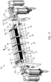
- FIG 11 shows a perspective view of a product conveying device 101 of the further embodiment according to the fifth aspect of the invention.
- the product conveying device 101 comprises a cassette receptacle 103, which is essentially formed by the frame 105 and the cylindrical shaft guide 107.
- the product conveying device 101 also comprises the detachably arranged cassette 109.
- the cassette 109 comprises the free-running support rollers 51.
- the four traction rollers 49 which in this embodiment are not part of the cassette 109, are arranged coaxially in the product conveying device 101.
- the product conveying device 101 is designed with four tracks.
- the upper vertices of the support rollers 51 can be at exactly the same height as the upper vertex of the respective traction roller 49, but they can also be aligned at a slightly different height.
- the food products 63 are conveyed along the conveying direction 100.
- the left conveyor track is referred to as the first conveyor track 10
- the right conveyor track as the second conveyor track 20
- the middle conveyor tracks as the third conveyor track 30 and fourth conveyor track 40.
- the traction roller 49 of the first conveyor track 10 is driven by the first, coaxially arranged drive shaft 111.
- the traction roller 49 of the second conveyor track 20 is driven by the second, coaxially arranged drive shaft 113.
- This designation for the first and second conveyor tracks 10, 20 was chosen because it corresponds to the basic structure in the case of a two-track machine, with a right and left conveyor track 10, 20 each driven on one side by the associated drive shafts 111, 113.
- Middle tracks are added as an extension of the concept, including associated separate drive shafts 115, 117.
- the traction roller 49 of the third conveyor track 30 is driven by a third drive shaft 115 arranged offset in parallel.
- the traction roller 49 of the fourth conveyor track 40 is driven by a fourth drive shaft 117 arranged offset in parallel.
- Drive rollers 83 are arranged at the ends of the third and fourth drive shafts 115, 117.
- the traction rollers 49 of the third and fourth conveyor tracks 30, 40 have a first circumferential region 85 and a second circumferential region 87, and a rotating drive means 81 rotates around the second circumferential region 87 and the drive roller 83 to drive the traction rollers 49.
- the circumference of the second circumferential region 87 with the drive means 81 is smaller than the circumference of the first circumferential region 85.
- the cassette 109 has circular-arc-shaped recesses 121 on its lateral parts of the cassette frame 119, with which the cassette 109 is attached to the circular-cylindrical shaft guides 107.
- the shaft guides 107 have additional notches 123, which also fix the cassette 109 laterally.
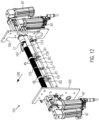
- Figure 12 shows a perspective view of the product conveying device 101 of Figure 11 without cassette 109.
- the drive motors 67 for the respective drive shafts 111, 113, 115, 117 can be seen on the sides of the frame 105.
- the four traction rollers 49 are mounted on a common bearing 125, which is supported by a support 127 on a cross-member-like cross member 129 of the frame 105.
- the traction rollers 49 can be removed from the product conveyor device 101 together with the bearing 125 by releasing the support 127, pulling the bearing 125 with the traction rollers 49 downwards out of the couplings 77, and loosening the flanged disks 131 of the drive rollers 83 in order to remove the drive means 81.
- the notch 123, onto which the cassette 109 is placed, can be seen on the shaft guide 107.
- Figure 13 shows a perspective view of a cassette 109 of the product conveying device 101 of Figure 11 .
- the cassette frame 119 In the cassette frame 119, four support rollers 51 are arranged per conveyor track 10, 20, 30, 40.
- a circular arc-shaped recess 121 is formed, each of which is in turn formed or enclosed by a first leg 133 and a second leg 135.
- One or both legs 133, 135 can be elastically loaded so that the recess 121 can be plugged onto the circular cylindrical shaft guide 107.
- a lateral handle 137 is used for handling, in order to pivot and remove the cassette 109 when removing it from a locking device.
- Figure 14 shows a perspective view of the product conveying device 101 of Figure 11 Viewed opposite to the conveying direction 100, with the cassette 109 pivoted upward for removal.
- a locking mechanism 139 is opened, for example, by pulling a bolt preloaded inward by a spring outward.
- the cassette 109 is then pivoted upward and removed from the cylindrical shaft guide 107.
- Figure 15 shows a perspective view of another embodiment of a cassette 109 with a cassette frame 119 and an upwardly pivoted roller module 141.
- the roller module 141 is mounted on the cassette frame 119 and is removable therefrom.
- the roller module 141 can be exchanged, for example, to provide a different number of conveyor tracks 10, 20, 30, 40.
- Figure 16 shows a perspective view of a roller module 141 of the cassette 109 of Figure 15 .
- the roller module 141 can be mounted on internal lateral supports (see Figure 17 ) of the cassette frame 119.
- the roller module 141 can be adjusted in height relative to the cassette frame 119, for example, to slightly adjust the height with respect to a cutting edge.
- Figure 17 shows a perspective view of the cassette frame 119 of the cassette 109 of Figure 15 .
- the recesses 143 of the roller module 141 can be plugged onto the lateral supports 147 in order to place the roller module 141 in the cassette frame 119.
- Figure 18 shows a schematic view of another embodiment of a product conveying device 101 according to the fifth aspect of the invention.
- the traction rollers 49 are arranged offset from the drive shafts 111, 113, 115, 117 in the conveying direction 100 and are thus positioned closer to a cutting edge.
- Circulating drive means 81 extend from the drive shafts 111, 113, 115, 117, of which the first drive shaft 111 and the second drive shaft 113 are visible here, to the traction rollers in order to drive them.
- the inner traction rollers 49 of the third conveyor track 30 and the fourth conveyor track 40 have a first circumferential region 85 and a second circumferential region 87, wherein the drive means 81 rotates around the second circumferential region 87, wherein the diameter 60 of the second circumferential region 87 and of the supporting drive means 81 is smaller than the diameter 50 of the first circumferential region 85 (cf. Figure 7 ).
- the rotating drive means 81 does not come into contact with the conveyed food product 63, which rests on the first circumferential region 85.
- the third and fourth drive shafts 115, 117 are offset downwards relative to the traction rollers 49.
- the third and fourth drive shafts 115, 117 are offset downwards but in the same position in the conveying direction 100 as the first and second drive shafts 111, 113. However, they could also be placed further downstream in the conveying direction 100.
- the cassette 109 comprises the free-running support rollers 51, which can thus be removed together.
- the traction rollers 49 of the outer conveyor tracks 10, 20 comprise outwardly facing roller extensions 149 around which the drive means 81 rotate.
- the drive means 81 are arranged outside the conveyor tracks 10, 20, wherein the conveyor tracks 10, 20 are formed by the traction rollers 49 with their first circumferential region 85 and the width of the support rollers 51.
- the roller extensions 149 also have a smaller diameter than the remaining part of the traction rollers 49.
Landscapes
- Life Sciences & Earth Sciences (AREA)
- Forests & Forestry (AREA)
- Engineering & Computer Science (AREA)
- Mechanical Engineering (AREA)
- Rollers For Roller Conveyors For Transfer (AREA)
- Structure Of Belt Conveyors (AREA)
- Details Of Cutting Devices (AREA)
Priority Applications (6)
| Application Number | Priority Date | Filing Date | Title |
|---|---|---|---|
| EP23157945.9A EP4420847B1 (de) | 2023-02-22 | 2023-02-22 | Produktfördervorrichtung mit traktionsrolle |
| ES23157945T ES3023632T3 (en) | 2023-02-22 | 2023-02-22 | Product conveying device with traction roller |
| PL23157945.9T PL4420847T3 (pl) | 2023-02-22 | 2023-02-22 | Urządzenie przenoszące produkty z rolką trakcyjną |
| CN202480014184.9A CN120752120A (zh) | 2023-02-22 | 2024-02-22 | 具有牵引辊的产品输送设备 |
| PCT/EP2024/054545 WO2024175724A1 (de) | 2023-02-22 | 2024-02-22 | Produktfördervorrichtung mit traktionsrolle |
| EP24705543.7A EP4669500A1 (de) | 2023-02-22 | 2024-02-22 | Produktfördervorrichtung mit traktionsrolle |
Applications Claiming Priority (1)
| Application Number | Priority Date | Filing Date | Title |
|---|---|---|---|
| EP23157945.9A EP4420847B1 (de) | 2023-02-22 | 2023-02-22 | Produktfördervorrichtung mit traktionsrolle |
Publications (2)
| Publication Number | Publication Date |
|---|---|
| EP4420847A1 EP4420847A1 (de) | 2024-08-28 |
| EP4420847B1 true EP4420847B1 (de) | 2025-04-02 |
Family
ID=85328961
Family Applications (2)
| Application Number | Title | Priority Date | Filing Date |
|---|---|---|---|
| EP23157945.9A Active EP4420847B1 (de) | 2023-02-22 | 2023-02-22 | Produktfördervorrichtung mit traktionsrolle |
| EP24705543.7A Pending EP4669500A1 (de) | 2023-02-22 | 2024-02-22 | Produktfördervorrichtung mit traktionsrolle |
Family Applications After (1)
| Application Number | Title | Priority Date | Filing Date |
|---|---|---|---|
| EP24705543.7A Pending EP4669500A1 (de) | 2023-02-22 | 2024-02-22 | Produktfördervorrichtung mit traktionsrolle |
Country Status (5)
| Country | Link |
|---|---|
| EP (2) | EP4420847B1 (pl) |
| CN (1) | CN120752120A (pl) |
| ES (1) | ES3023632T3 (pl) |
| PL (1) | PL4420847T3 (pl) |
| WO (1) | WO2024175724A1 (pl) |
Family Cites Families (4)
| Publication number | Priority date | Publication date | Assignee | Title |
|---|---|---|---|---|
| DE102013206510A1 (de) * | 2012-12-03 | 2014-06-05 | Textor Maschinenbau GmbH | Hochleistungsaufschnittschneidemaschine mit zumindest einer entnehmbaren Bandkassette |
| CA2948158C (en) * | 2014-05-07 | 2019-04-23 | Formax, Inc. | Food product slicing apparatus and methods |
| US9962849B2 (en) * | 2015-05-07 | 2018-05-08 | Eric J Wangler | Washable stacker apparatus with self-tensioning feature for use with a food slicing machine |
| CN209831826U (zh) * | 2019-02-25 | 2019-12-24 | 福建坤兴海洋股份有限公司 | 一种切片切块机 |
-
2023
- 2023-02-22 ES ES23157945T patent/ES3023632T3/es active Active
- 2023-02-22 PL PL23157945.9T patent/PL4420847T3/pl unknown
- 2023-02-22 EP EP23157945.9A patent/EP4420847B1/de active Active
-
2024
- 2024-02-22 WO PCT/EP2024/054545 patent/WO2024175724A1/de not_active Ceased
- 2024-02-22 EP EP24705543.7A patent/EP4669500A1/de active Pending
- 2024-02-22 CN CN202480014184.9A patent/CN120752120A/zh active Pending
Also Published As
| Publication number | Publication date |
|---|---|
| PL4420847T3 (pl) | 2025-08-18 |
| EP4669500A1 (de) | 2025-12-31 |
| ES3023632T3 (en) | 2025-06-02 |
| WO2024175724A1 (de) | 2024-08-29 |
| CN120752120A (zh) | 2025-10-03 |
| EP4420847A1 (de) | 2024-08-28 |
Similar Documents
| Publication | Publication Date | Title |
|---|---|---|
| DE3302946C2 (de) | Drei-Messer-Schneidemaschine | |
| DE68903016T2 (de) | Vorrichtung zum Verschliessen von Behältern mittels einer versiegelbaren Folie. | |
| DE19860018A1 (de) | Verpackungsautomat zur Konfektionierung von Produkten | |
| DE10157953B4 (de) | Fördervorrichtung für Maschinen zur Verpackung von Rollen und dergleichen | |
| DE60113580T2 (de) | Schneidemaschine für eine Vielzahl von Küchen- und/oder Toiletten-Papierrollen | |
| DE3042519A1 (de) | Vorrichtung zum stapeln von produkten | |
| EP3246260B1 (de) | Vorrichtung zur zuführung von produktträgern und vorrichtung zum verschwenken eines abdeckabschnitts eines produktträgers | |
| DE2718028C2 (de) | Semmelschneidmaschine | |
| EP0698451B1 (de) | Verfahren und Einrichtung zum Beschneiden von flachen Druckprodukten längs einer vorgegebenen Schnittlinie | |
| DE4017692C2 (pl) | ||
| DE3151017C2 (pl) | ||
| DE69502995T2 (de) | Maschine zum Verpacken von Kleidungsstücken, wie Strümpfe oder dergleichen, in Schachteln | |
| WO2013113828A1 (de) | Verfahren und vorrichtung zum trennen und stapeln von lebensmittelscheiben | |
| EP4000824B1 (de) | Vorrichtung zum zuschneiden von lebensmittelverpackungen entlang einer längsrichtung und verfahren zum betreiben einer solchen vorrichtung | |
| DE3113399A1 (de) | Ausrichtvorrichtung fuer die kanten eines aus falzprodukten bestehenden schuppenstroms | |
| EP4420847B1 (de) | Produktfördervorrichtung mit traktionsrolle | |
| DE3340907A1 (de) | Speckschnittenmaschine | |
| DE102008006688A1 (de) | Lebensmittel-Schneidemaschine und Verfahren zur Einstellung einer Schnittgutscheibendicke bei einer Lebensmittel-Schneidemaschine | |
| DE2446364B2 (de) | Vorrichtung zum Transport von Bogen | |
| EP2112069B1 (de) | Verfahren und Vorrichtung zum Verpacken von portionierten Produkten in einem Einwickler | |
| EP2295320A2 (de) | Vorrichtung und Verfahren zum Handhaben von Stapeln aus Druckträgern | |
| DE202004010068U1 (de) | Wendevorrichtung zum Handhaben von Packungen aus gefalteten blattförmigen Produkten | |
| EP4420846B1 (de) | Produktführung mit traktionsrolle | |
| EP1258325A2 (de) | Verfahren und Vorrichtung zum Schneiden von Wurst, Käse oder ähnlichen Lebensmitteln in Scheiben | |
| DE102007041254A1 (de) | Vorrichtung zum Drehen von gefaltetem Material |
Legal Events
| Date | Code | Title | Description |
|---|---|---|---|
| PUAI | Public reference made under article 153(3) epc to a published international application that has entered the european phase |
Free format text: ORIGINAL CODE: 0009012 |
|
| STAA | Information on the status of an ep patent application or granted ep patent |
Free format text: STATUS: REQUEST FOR EXAMINATION WAS MADE |
|
| 17P | Request for examination filed |
Effective date: 20231020 |
|
| AK | Designated contracting states |
Kind code of ref document: A1 Designated state(s): AL AT BE BG CH CY CZ DE DK EE ES FI FR GB GR HR HU IE IS IT LI LT LU LV MC ME MK MT NL NO PL PT RO RS SE SI SK SM TR |
|
| GRAP | Despatch of communication of intention to grant a patent |
Free format text: ORIGINAL CODE: EPIDOSNIGR1 |
|
| STAA | Information on the status of an ep patent application or granted ep patent |
Free format text: STATUS: GRANT OF PATENT IS INTENDED |
|
| GRAS | Grant fee paid |
Free format text: ORIGINAL CODE: EPIDOSNIGR3 |
|
| INTG | Intention to grant announced |
Effective date: 20241112 |
|
| RIN1 | Information on inventor provided before grant (corrected) |
Inventor name: BAUMEISTER, CHRISTIAN Inventor name: GARAEW, SERGEJ |
|
| P01 | Opt-out of the competence of the unified patent court (upc) registered |
Free format text: CASE NUMBER: APP_67425/2024 Effective date: 20241220 |
|
| GRAA | (expected) grant |
Free format text: ORIGINAL CODE: 0009210 |
|
| STAA | Information on the status of an ep patent application or granted ep patent |
Free format text: STATUS: THE PATENT HAS BEEN GRANTED |
|
| RAP1 | Party data changed (applicant data changed or rights of an application transferred) |
Owner name: WEBER FOOD TECHNOLOGY SE & CO. KG |
|
| AK | Designated contracting states |
Kind code of ref document: B1 Designated state(s): AL AT BE BG CH CY CZ DE DK EE ES FI FR GB GR HR HU IE IS IT LI LT LU LV MC ME MK MT NL NO PL PT RO RS SE SI SK SM TR |
|
| REG | Reference to a national code |
Ref country code: GB Ref legal event code: FG4D Free format text: NOT ENGLISH |
|
| REG | Reference to a national code |
Ref country code: CH Ref legal event code: EP |
|
| REG | Reference to a national code |
Ref country code: IE Ref legal event code: FG4D Free format text: LANGUAGE OF EP DOCUMENT: GERMAN |
|
| REG | Reference to a national code |
Ref country code: DE Ref legal event code: R096 Ref document number: 502023000749 Country of ref document: DE |
|
| REG | Reference to a national code |
Ref country code: NL Ref legal event code: FP |
|
| REG | Reference to a national code |
Ref country code: ES Ref legal event code: FG2A Ref document number: 3023632 Country of ref document: ES Kind code of ref document: T3 Effective date: 20250602 |
|
| PG25 | Lapsed in a contracting state [announced via postgrant information from national office to epo] |
Ref country code: FI Free format text: LAPSE BECAUSE OF FAILURE TO SUBMIT A TRANSLATION OF THE DESCRIPTION OR TO PAY THE FEE WITHIN THE PRESCRIBED TIME-LIMIT Effective date: 20250402 Ref country code: PT Free format text: LAPSE BECAUSE OF FAILURE TO SUBMIT A TRANSLATION OF THE DESCRIPTION OR TO PAY THE FEE WITHIN THE PRESCRIBED TIME-LIMIT Effective date: 20250804 |
|
| REG | Reference to a national code |
Ref country code: LT Ref legal event code: MG9D |
|
| PG25 | Lapsed in a contracting state [announced via postgrant information from national office to epo] |
Ref country code: NO Free format text: LAPSE BECAUSE OF FAILURE TO SUBMIT A TRANSLATION OF THE DESCRIPTION OR TO PAY THE FEE WITHIN THE PRESCRIBED TIME-LIMIT Effective date: 20250702 Ref country code: GR Free format text: LAPSE BECAUSE OF FAILURE TO SUBMIT A TRANSLATION OF THE DESCRIPTION OR TO PAY THE FEE WITHIN THE PRESCRIBED TIME-LIMIT Effective date: 20250703 |
|
| PG25 | Lapsed in a contracting state [announced via postgrant information from national office to epo] |
Ref country code: BG Free format text: LAPSE BECAUSE OF FAILURE TO SUBMIT A TRANSLATION OF THE DESCRIPTION OR TO PAY THE FEE WITHIN THE PRESCRIBED TIME-LIMIT Effective date: 20250402 |
|
| PG25 | Lapsed in a contracting state [announced via postgrant information from national office to epo] |
Ref country code: HR Free format text: LAPSE BECAUSE OF FAILURE TO SUBMIT A TRANSLATION OF THE DESCRIPTION OR TO PAY THE FEE WITHIN THE PRESCRIBED TIME-LIMIT Effective date: 20250402 |
|
| PG25 | Lapsed in a contracting state [announced via postgrant information from national office to epo] |
Ref country code: RS Free format text: LAPSE BECAUSE OF FAILURE TO SUBMIT A TRANSLATION OF THE DESCRIPTION OR TO PAY THE FEE WITHIN THE PRESCRIBED TIME-LIMIT Effective date: 20250702 |
|
| PG25 | Lapsed in a contracting state [announced via postgrant information from national office to epo] |
Ref country code: IS Free format text: LAPSE BECAUSE OF FAILURE TO SUBMIT A TRANSLATION OF THE DESCRIPTION OR TO PAY THE FEE WITHIN THE PRESCRIBED TIME-LIMIT Effective date: 20250802 |
|
| PG25 | Lapsed in a contracting state [announced via postgrant information from national office to epo] |
Ref country code: LV Free format text: LAPSE BECAUSE OF FAILURE TO SUBMIT A TRANSLATION OF THE DESCRIPTION OR TO PAY THE FEE WITHIN THE PRESCRIBED TIME-LIMIT Effective date: 20250402 |
|
| PG25 | Lapsed in a contracting state [announced via postgrant information from national office to epo] |
Ref country code: SM Free format text: LAPSE BECAUSE OF FAILURE TO SUBMIT A TRANSLATION OF THE DESCRIPTION OR TO PAY THE FEE WITHIN THE PRESCRIBED TIME-LIMIT Effective date: 20250402 Ref country code: DK Free format text: LAPSE BECAUSE OF FAILURE TO SUBMIT A TRANSLATION OF THE DESCRIPTION OR TO PAY THE FEE WITHIN THE PRESCRIBED TIME-LIMIT Effective date: 20250402 |
|
| PG25 | Lapsed in a contracting state [announced via postgrant information from national office to epo] |
Ref country code: CZ Free format text: LAPSE BECAUSE OF FAILURE TO SUBMIT A TRANSLATION OF THE DESCRIPTION OR TO PAY THE FEE WITHIN THE PRESCRIBED TIME-LIMIT Effective date: 20250402 |
|
| PG25 | Lapsed in a contracting state [announced via postgrant information from national office to epo] |
Ref country code: EE Free format text: LAPSE BECAUSE OF FAILURE TO SUBMIT A TRANSLATION OF THE DESCRIPTION OR TO PAY THE FEE WITHIN THE PRESCRIBED TIME-LIMIT Effective date: 20250402 |
|
| PG25 | Lapsed in a contracting state [announced via postgrant information from national office to epo] |
Ref country code: SK Free format text: LAPSE BECAUSE OF FAILURE TO SUBMIT A TRANSLATION OF THE DESCRIPTION OR TO PAY THE FEE WITHIN THE PRESCRIBED TIME-LIMIT Effective date: 20250402 |
|
| PLBE | No opposition filed within time limit |
Free format text: ORIGINAL CODE: 0009261 |
|
| STAA | Information on the status of an ep patent application or granted ep patent |
Free format text: STATUS: NO OPPOSITION FILED WITHIN TIME LIMIT |
|
| REG | Reference to a national code |
Ref country code: CH Ref legal event code: L10 Free format text: ST27 STATUS EVENT CODE: U-0-0-L10-L00 (AS PROVIDED BY THE NATIONAL OFFICE) Effective date: 20260211 |