EP4415150A2 - Stromabnahmeelement, energiespeichervorrichtung und stromverbrauchende vorrichtung - Google Patents
Stromabnahmeelement, energiespeichervorrichtung und stromverbrauchende vorrichtung Download PDFInfo
- Publication number
- EP4415150A2 EP4415150A2 EP23213229.0A EP23213229A EP4415150A2 EP 4415150 A2 EP4415150 A2 EP 4415150A2 EP 23213229 A EP23213229 A EP 23213229A EP 4415150 A2 EP4415150 A2 EP 4415150A2
- Authority
- EP
- European Patent Office
- Prior art keywords
- adapter
- corners
- insulator
- connecting portion
- current collecting
- Prior art date
- Legal status (The legal status is an assumption and is not a legal conclusion. Google has not performed a legal analysis and makes no representation as to the accuracy of the status listed.)
- Granted
Links
Images





Classifications
-
- H—ELECTRICITY
- H01—ELECTRIC ELEMENTS
- H01M—PROCESSES OR MEANS, e.g. BATTERIES, FOR THE DIRECT CONVERSION OF CHEMICAL ENERGY INTO ELECTRICAL ENERGY
- H01M50/00—Constructional details or processes of manufacture of the non-active parts of electrochemical cells other than fuel cells, e.g. hybrid cells
- H01M50/10—Primary casings; Jackets or wrappings
- H01M50/102—Primary casings; Jackets or wrappings characterised by their shape or physical structure
- H01M50/103—Primary casings; Jackets or wrappings characterised by their shape or physical structure prismatic or rectangular
-
- H—ELECTRICITY
- H01—ELECTRIC ELEMENTS
- H01M—PROCESSES OR MEANS, e.g. BATTERIES, FOR THE DIRECT CONVERSION OF CHEMICAL ENERGY INTO ELECTRICAL ENERGY
- H01M50/00—Constructional details or processes of manufacture of the non-active parts of electrochemical cells other than fuel cells, e.g. hybrid cells
- H01M50/10—Primary casings; Jackets or wrappings
- H01M50/147—Lids or covers
- H01M50/148—Lids or covers characterised by their shape
- H01M50/15—Lids or covers characterised by their shape for prismatic or rectangular cells
-
- H—ELECTRICITY
- H01—ELECTRIC ELEMENTS
- H01M—PROCESSES OR MEANS, e.g. BATTERIES, FOR THE DIRECT CONVERSION OF CHEMICAL ENERGY INTO ELECTRICAL ENERGY
- H01M50/00—Constructional details or processes of manufacture of the non-active parts of electrochemical cells other than fuel cells, e.g. hybrid cells
- H01M50/10—Primary casings; Jackets or wrappings
- H01M50/172—Arrangements of electric connectors penetrating the casing
- H01M50/174—Arrangements of electric connectors penetrating the casing adapted for the shape of the cells
- H01M50/176—Arrangements of electric connectors penetrating the casing adapted for the shape of the cells for prismatic or rectangular cells
-
- H—ELECTRICITY
- H01—ELECTRIC ELEMENTS
- H01M—PROCESSES OR MEANS, e.g. BATTERIES, FOR THE DIRECT CONVERSION OF CHEMICAL ENERGY INTO ELECTRICAL ENERGY
- H01M50/00—Constructional details or processes of manufacture of the non-active parts of electrochemical cells other than fuel cells, e.g. hybrid cells
- H01M50/50—Current conducting connections for cells or batteries
- H01M50/528—Fixed electrical connections, i.e. not intended for disconnection
-
- H—ELECTRICITY
- H01—ELECTRIC ELEMENTS
- H01M—PROCESSES OR MEANS, e.g. BATTERIES, FOR THE DIRECT CONVERSION OF CHEMICAL ENERGY INTO ELECTRICAL ENERGY
- H01M50/00—Constructional details or processes of manufacture of the non-active parts of electrochemical cells other than fuel cells, e.g. hybrid cells
- H01M50/50—Current conducting connections for cells or batteries
- H01M50/531—Electrode connections inside a battery casing
- H01M50/533—Electrode connections inside a battery casing characterised by the shape of the leads or tabs
-
- H—ELECTRICITY
- H01—ELECTRIC ELEMENTS
- H01M—PROCESSES OR MEANS, e.g. BATTERIES, FOR THE DIRECT CONVERSION OF CHEMICAL ENERGY INTO ELECTRICAL ENERGY
- H01M50/00—Constructional details or processes of manufacture of the non-active parts of electrochemical cells other than fuel cells, e.g. hybrid cells
- H01M50/50—Current conducting connections for cells or batteries
- H01M50/531—Electrode connections inside a battery casing
- H01M50/538—Connection of several leads or tabs of wound or folded electrode stacks
-
- H—ELECTRICITY
- H01—ELECTRIC ELEMENTS
- H01M—PROCESSES OR MEANS, e.g. BATTERIES, FOR THE DIRECT CONVERSION OF CHEMICAL ENERGY INTO ELECTRICAL ENERGY
- H01M50/00—Constructional details or processes of manufacture of the non-active parts of electrochemical cells other than fuel cells, e.g. hybrid cells
- H01M50/50—Current conducting connections for cells or batteries
- H01M50/543—Terminals
- H01M50/547—Terminals characterised by the disposition of the terminals on the cells
- H01M50/55—Terminals characterised by the disposition of the terminals on the cells on the same side of the cell
-
- H—ELECTRICITY
- H01—ELECTRIC ELEMENTS
- H01M—PROCESSES OR MEANS, e.g. BATTERIES, FOR THE DIRECT CONVERSION OF CHEMICAL ENERGY INTO ELECTRICAL ENERGY
- H01M50/00—Constructional details or processes of manufacture of the non-active parts of electrochemical cells other than fuel cells, e.g. hybrid cells
- H01M50/50—Current conducting connections for cells or batteries
- H01M50/572—Means for preventing undesired use or discharge
- H01M50/574—Devices or arrangements for the interruption of current
- H01M50/581—Devices or arrangements for the interruption of current in response to temperature
-
- H—ELECTRICITY
- H01—ELECTRIC ELEMENTS
- H01M—PROCESSES OR MEANS, e.g. BATTERIES, FOR THE DIRECT CONVERSION OF CHEMICAL ENERGY INTO ELECTRICAL ENERGY
- H01M50/00—Constructional details or processes of manufacture of the non-active parts of electrochemical cells other than fuel cells, e.g. hybrid cells
- H01M50/50—Current conducting connections for cells or batteries
- H01M50/572—Means for preventing undesired use or discharge
- H01M50/574—Devices or arrangements for the interruption of current
- H01M50/583—Devices or arrangements for the interruption of current in response to current, e.g. fuses
-
- H—ELECTRICITY
- H01—ELECTRIC ELEMENTS
- H01M—PROCESSES OR MEANS, e.g. BATTERIES, FOR THE DIRECT CONVERSION OF CHEMICAL ENERGY INTO ELECTRICAL ENERGY
- H01M50/00—Constructional details or processes of manufacture of the non-active parts of electrochemical cells other than fuel cells, e.g. hybrid cells
- H01M50/50—Current conducting connections for cells or batteries
- H01M50/572—Means for preventing undesired use or discharge
- H01M50/584—Means for preventing undesired use or discharge for preventing incorrect connections inside or outside the batteries
- H01M50/586—Means for preventing undesired use or discharge for preventing incorrect connections inside or outside the batteries inside the batteries, e.g. incorrect connections of electrodes
-
- H—ELECTRICITY
- H01—ELECTRIC ELEMENTS
- H01M—PROCESSES OR MEANS, e.g. BATTERIES, FOR THE DIRECT CONVERSION OF CHEMICAL ENERGY INTO ELECTRICAL ENERGY
- H01M50/00—Constructional details or processes of manufacture of the non-active parts of electrochemical cells other than fuel cells, e.g. hybrid cells
- H01M50/50—Current conducting connections for cells or batteries
- H01M50/572—Means for preventing undesired use or discharge
- H01M50/584—Means for preventing undesired use or discharge for preventing incorrect connections inside or outside the batteries
- H01M50/59—Means for preventing undesired use or discharge for preventing incorrect connections inside or outside the batteries characterised by the protection means
-
- H—ELECTRICITY
- H01—ELECTRIC ELEMENTS
- H01M—PROCESSES OR MEANS, e.g. BATTERIES, FOR THE DIRECT CONVERSION OF CHEMICAL ENERGY INTO ELECTRICAL ENERGY
- H01M2200/00—Safety devices for primary or secondary batteries
- H01M2200/10—Temperature sensitive devices
- H01M2200/103—Fuse
-
- Y—GENERAL TAGGING OF NEW TECHNOLOGICAL DEVELOPMENTS; GENERAL TAGGING OF CROSS-SECTIONAL TECHNOLOGIES SPANNING OVER SEVERAL SECTIONS OF THE IPC; TECHNICAL SUBJECTS COVERED BY FORMER USPC CROSS-REFERENCE ART COLLECTIONS [XRACs] AND DIGESTS
- Y02—TECHNOLOGIES OR APPLICATIONS FOR MITIGATION OR ADAPTATION AGAINST CLIMATE CHANGE
- Y02E—REDUCTION OF GREENHOUSE GAS [GHG] EMISSIONS, RELATED TO ENERGY GENERATION, TRANSMISSION OR DISTRIBUTION
- Y02E60/00—Enabling technologies; Technologies with a potential or indirect contribution to GHG emissions mitigation
- Y02E60/10—Energy storage using batteries
Definitions
- the present disclosure relates to the technical field of energy storage, and in particular, to a current collecting member, an energy storage device, and a power consuming apparatus.
- an adapter is configured to connect a pole to an electrode assembly for current transmission.
- a fuse portion with a narrowed dimension is usually formed in an intermediate region of the adapter, and the formation of the fuse portion easily leads to cuts of the electrode assembly, which causes damages to the electrode assembly and thus affects the use safety and service life of a secondary battery.
- a current collecting member is provided in a first aspect of the present disclosure, for improving the safety and service life of a secondary battery.
- the current collecting member is for an energy storage device.
- the current collecting member includes an adapter and an insulator.
- the adapter includes a first surface and a second surface that are arranged in a thickness direction of the adapter itself, the first surface is located on a side of the adapter that faces an electrode assembly of the energy storage device, and the second surface is located on a side of the adapter that faces away from the electrode assembly of the energy storage device.
- the adapter includes a first connecting portion, a fuse portion and a second connecting portion in a length direction of the adapter, and the fuse portion is connected between the first connecting portion and the second connecting portion.
- a ratio of the width of the fuse portion in a width direction of the adapter to the width of the first connecting portion and a ratio of the width of the fuse portion in the width direction of the adapter to the width of the second connecting portion each are in a range from 1/6 to 4/5.
- the first connecting portion is provided with first corners at an end of the first connecting portion close to the second connecting portion
- the second connecting portion is provided with second corners at an end of the second connecting portion close to the first connecting portion.
- the insulator is provided with a first protective portion, a second protective portion and a third protective portion in the length direction of the adapter.
- the first protective portion covers the first corners
- the second protective portion covers the second corners
- the third protective portion is connected between the first protective portion and the second protective portion
- the third protective portion covers a first surface of the fuse portion of the adapter
- a second surface of the fuse portion is at least partially exposed from the insulator.
- the first protective portion may cover the first corners and the second protective portion may cover the second corners, in other words, the first corners are arranged in the first protective portion and the second corners are arranged in the second protective portion.
- the electrode assembly may be brought into contact with the first protective portion on the peripheries of the first corners and the second protective portion on the peripheries of the second corners, thereby preventing the electrode assembly from contact with the first corners and the second corners around the fuse portion, preventing the electrode assembly from being cut by the first corners and the second corners, and effectively protecting the electrode assembly.
- the third protective portion may cover the fuse portion of the adapter, thereby providing a buffer for the fuse portion, effectively protecting the fuse portion, preventing the fuse portion from fracturing due to the vibration of the current collecting member, and increasing the structural strength of the current collecting member.
- the third protective portion may also cover sharp edges on each side of the fuse portion, thereby preventing the edges of the fuse portion from cutting the electrode assembly.
- the adapter further includes a transition, the transition is connected between the fuse portion and the first connecting portion, the transition has two first corners arranged opposite to each other in the width direction of the adapter at an end of the transition close to the fuse portion, the second connecting portion has two second corners arranged opposite to each other in the width direction of the adapter at an end of the second connecting portion close to the fuse portion, and the third protective portion is connected between the first protective portion and the second protective portion.
- the insulator In the length direction of the adapter, the insulator has a dimension L1, and a distance L2 between the first connecting portion and the second connecting portion satisfies 0.01 mm ⁇ L1-L2 ⁇ 3.1 mm.
- the insulator In the width direction of the adapter, the insulator has a dimension of L3, and the adapter has a width of L4, where 0.01 mm ⁇ L3-L4 ⁇ 2.4 mm.
- the insulator defines a stepped recess in a surface of the insulator close to the second surface of the adapter, a bottom wall of the stepped recess is provided with an injection-molded necking portion, and the height of the injection-molded necking portion is less than or equal to the depth of the stepped recess.
- the ratio of the height of the injection-molded necking portion to the depth of the stepped recess is greater than or equal to 1/10 and less than or equal to 9/10.
- the height of the injection-molded necking portion ranges from 0.06 mm to 0.31 mm.
- first recesses are defined in a surface of the transition that faces the insulator, the insulator is provided with an extension on a surface of the insulator close to the first surface, multiple second recesses are defined in a surface of the extension away from the transition, and in a thickness direction of the energy storage device, orthogonal projection planes of the multiple second recesses at least partially overlap with orthogonal projection planes of the multiple first recesses.
- the third protective portion includes a first covering portion, the first covering portion being provided with a projection protruding in the length direction of the adapter, the projection covering an end of the fuse portion adjacent to the second connecting portion, and an end of the fuse portion away from the second connecting portion being exposed.
- the third protective portion further includes a second covering portion covering an end of the fuse portion close to an edge of the adapter.
- the first corners and the second corners are rounded corners, each of the first corners has an arc radius ranging from 2.1 to 3.6 mm, and each of the second corners has an arc radius ranging from 2.1 to 3.6 mm.
- An energy storage device in a second aspect of the present disclosure.
- the energy storage device includes: a housing having an opening, the housing defining an accommodating cavity; an electrode assembly accommodated inside the accommodating cavity; an end cap assembly covering the opening; a pole assembly arranged in the end cap assembly, the pole assembly including a flange; a lower plastic part arranged between the electrode assembly and the end cap assembly; and a current collecting member provided in the first aspect of the present disclosure, where the current collecting member is arranged on a side of the lower plastic part away from the end cap assembly, the first connecting portion of the current collecting member is electrically connected to the pole assembly, and the second connecting portion of the current collecting member is electrically connected to the electrode assembly.
- the first protective portion may cover the first corners and the second protective portion may cover the second corners, in other words, the first corners are arranged in the first protective portion and the second corners are arranged in the second protective portion.
- the electrode assembly may be brought into contact with the first protective portion on the peripheries of the first corners and the second protective portion on the peripheries of the second corners, thereby preventing the electrode assembly from contact with the first corners and the second corners around the fuse portion, preventing the electrode assembly from being cut by the first corners and the second corners, and effectively protecting the electrode assembly.
- the third protective portion may cover the fuse portion of the adapter, thereby providing a buffer for the fuse portion, effectively protecting the fuse portion, preventing the fuse portion from fracturing due to the vibration of the current collecting member, and increasing the structural strength of the current collecting member.
- the third protective portion may also cover sharp edges on each side of the fuse portion to prevent the edges of the fuse portion from cutting the electrode assembly, which not only effectively protects the energy storage device, but also improves the use safety and service life of the energy storage device.
- An avoidance recess is defined in a surface of the lower plastic part close to the current collecting member, and the insulator is at least partially accommodated inside the avoidance recess.
- a stepped recess is defined in the surface of the insulator close to the second surface of the adapter.
- the stepped recess includes a first recess and a second recess that are arranged opposite to each other in the width direction of the adapter.
- the fuse portion is arranged between the first recess and the second recess.
- a side of the first recess close to the flange and a side of the second recess close to the flange define a connecting line L, and an end of the flange adjacent to the fuse portion extends beyond the connecting line L towards the insulator.
- a power consuming apparatus is provided in a third aspect of the present disclosure.
- the power consuming apparatus includes an energy storage device provided in the second aspect of the present disclosure, and the energy storage device supplying power to the power consuming apparatus.
- the first protective portion may cover the first corners and the second protective portion may cover the second corners, in other words, the first corners are arranged in the first protective portion and the second corners are arranged in the second protective portion.
- the electrode assembly may be brought into contact with the first protective portion on the peripheries of the first corners and the second protective portion on the peripheries of the second corners, thereby preventing the electrode assembly from contact with the first corners and the second corners around the fuse portion, preventing the electrode assembly from being cut by the first corners and the second corners, and effectively protecting the electrode assembly.
- the third protective portion may cover the fuse portion of the adapter, thereby providing a buffer for the fuse portion, effectively protecting the fuse portion, preventing the fuse portion from fracturing due to the vibration of the current collecting member, and increasing the structural strength of the current collecting member.
- the third protective portion may also cover sharp edges on each side of the fuse portion to prevent the edges of the fuse portion from cutting the electrode assembly, which not only effectively protects the power consuming apparatus, but also improves the use safety and service life of the power consuming apparatus.
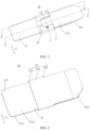
- Power consuming apparatus-100 energy storage device - 1, end cap assembly - 10, lower plastic part - 11, through hole - 110, grid structure - 111, avoidance recess - 112, second mounting hole - 113, upper rubber part - 12, top cap - 13, first mounting hole - 130, stress member - 14, pole assembly - 15, flange - 151, riveting portion - 152, current collecting member - 20, length direction - X, width direction - Y, thickness direction - Z, adapter - 21, first connecting portion - 211, transition - 212, first corners - 2120, first recess - 2121, fuse portion - 213, avoidance space - 2130, second connecting portion - 214, second corners - 2140, first surface - 215, second surface - 216, insulator - 22, stepped recess - 220, injection-molded necking portion - 2200, first recess - 2201, second recess - 2202, extension - 221, second reces
- this implementation provides a current collecting member 20 for an energy storage device 1.
- the current collecting member 20 includes an adapter 21 and an insulator 22.
- the adapter 21 includes a first surface 215 and a second surface 216 that are arranged in a thickness direction Z of the adapter itself, the first surface 215 is located on a side of the adapter 21 that faces an electrode assembly 30 of the energy storage device 1, and the second surface 216 is located on a side of the adapter 21 that faces away from the electrode assembly 30 of the energy storage device 1.
- the adapter 21 includes a first connecting portion 211, a fuse portion 213 and a second connecting portion 214 in a length direction X of the adapter 21, and the fuse portion 213 is connected between the first connecting portion 211 and the second connecting portion 214.
- a ratio of the width of the fuse portion 213 in a width direction Y of the adapter 21 to the width of the first connecting portion 211 and a ratio of the width of the fuse portion 213 in the width direction Y of the adapter 21 to the width of the second connecting portion 214 each are in a range from 1/6 to 4/5.
- the insulator 22 is provided with a first protective portion 226, a second protective portion 227 and a third protective portion 228 in the length direction X of the adapter 21.
- the first protective portion 226 covers the first corners 2120
- the second protective portion 227 covers the second corners 2140
- the third protective portion 228 is connected between the first protective portion 226 and the second protective portion 227
- the third protective portion 228 covers a first surface 215 of the fuse portion 213 of the adapter 21, and a second surface 216 of the fuse portion 213 is at least partially exposed from the insulator 22.
- the current collecting member 20 provided in this implementation is mainly for the energy storage device 1, and a pole assembly 15 and the electrode assembly 30 can be indirectly connected together by the current collecting member 20, so as to facilitate transmission of electrical signals such as currents.
- the current collecting member 20 mainly includes the adapter 21 and the insulator 22, which will be described in detail below.
- the current collecting member 20 may be a positive current collecting member and a negative current collecting member.
- the adapter 21 is a positive adapter.
- the adapter 21 is a negative adapter.
- This implementation is schematically described only with the current collecting member 20 as a positive current collecting member.
- the adapter 21 mainly servers to provide an electrical connection, that is, to enable indirect connection of the pole assembly 15 with the electrode assembly 30 as mentioned above.
- the adapter 21 includes a first surface 215 and a second surface 216 that are arranged in a thickness direction Z of the adapter itself, the first surface 215 is a side surface of the adapter 21 close to the electrode assembly 30, and the second surface 216 is a side surface of the adapter 21 that faces away from the electrode assembly 30.
- the first surface 215 is a lower surface of the adapter 21, and the second surface 216 is an upper surface of the adapter 21.
- the adapter 21 may include a first connecting portion 211, a fuse portion 213, and a second connecting portion 214, or in other implementations, the adapter 21 may also include a first connecting portion 211, a transition 212, a fuse portion 213, and a second connecting portion 214.
- the first connecting portion 211, the transition 212, the fuse portion 213 and the second connecting portion 214 are sequentially connected, that is, the first connecting portion 211 is connected to the transition 212, the fuse portion 213 is connected to a side of the transition 212 away from the first connecting portion 211, and the second connecting portion 214 is connected to a side of the fuse portion 213 away from the transition 212.
- the first connecting portion 211 is configured to be connected to the pole assembly 15, and the second connecting portion 214 is configured to be connected to the electrode assembly 30.
- the transition 212 may serve to connect the first connecting portion 211 and the fuse portion 213, and other structures may be further arranged on the transition 212 subsequently to achieve other functions. The specific structure of the transition 212 will be described in detail below in the present disclosure.
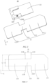
- the fuse portion 213 mainly provides a function of fusion. As shown in FIG. 4 , in this implementation, in the width direction Y of the adapter 21, the fuse portion 213 has a width (as shown by L5 in FIG. 4 ) less than the width (as shown by L4 in FIG. 4 ) of the first connecting portion 211 and the width (as shown by L4 in FIG. 4 ) of the second connecting portion 214. In other words, the adapter 21 is not of a flat and straight structure, and the fuse portion 213 is narrower the second connecting portion 214 and the first connecting portion 211 on each side thereof.
- a ratio of the width L5 of the fuse portion 213 to the width L4 of the first connecting portion 211 and a ratio of the width L5 of the fuse portion 213 to the width L4 of the second connecting portion 214 each are in a range from 1/6 to 4/5.
- the ratio of the width L5 of the fuse portion 213 to the width L4 of the first connecting portion 211 and the ratio of the width L5 of the fuse portion 213 to the width L5 of the second connecting portion 214 each may be 1/6, 0.2, 0.25, 0.3, 0.35, 0.4, 0.45, 0.5, 0.55, 0.6, 0.65, 0.7, 0.75, 0.8, etc.
- the fuse portion 213 may have a reduced cross-sectional area and an increased resistance.
- a relatively large current is generated and passes through the adapter 21, so the fuse portion 213 with a relatively large resistance generates more heat.
- the fuse portion 213 when the current passing through the current collecting member 20 reaches a fusing current, the fuse portion 213 is overheated and fused, such that the pole assembly 15 is electrically disconnected from the electrode assembly 30, thereby effectively protecting the energy storage device 1 so as to reduce accidents such as explosion and fire of the energy storage device 1.
- first connecting portion 211, the transition 212, the fuse portion 213 and the second connecting portion 214 may be of an integrated structure or a split structure, and this implementation is schematically described with the first connecting portion 211, the transition 212, the fuse portion 213 and the second connecting portion 214 as an integrated structure.
- the material of the adapter 21 includes, but is not limited to, metal, such as copper, aluminum, nickel, and an alloy thereof.
- the adapter 21 is a component of a three-dimensional structure with a certain dimension, and the adapter 21 has a length direction X, a width direction Y, and a thickness direction Z.
- the length direction X may be understood as an X direction in the figures, and the length direction X may also be understood as a direction in which the first connecting portion 211, the transition 212, the fuse portion 213 and the second connecting portion 214 are arranged.
- the width direction Y may be understood as a Y direction in the figures, and the width direction Y may also be understood as a direction in which the first connecting portion 211, the transition 212, the fuse portion 213 and the second connecting portion 214 are arranged.
- the thickness direction Z may be understood as a Z direction in the figures, and the thickness direction Z may also be understood as a direction perpendicular to both the length direction X and the width direction Y Furthermore, other components such as the energy storage device 1, the insulator 22, and the lower plastic part 11 also each have a length direction X, a width direction Y, and a thickness direction Z.
- the length direction X, the width direction Y and the thickness direction Z of the other components may be understood similarly as the length direction X, the width direction Y and the thickness direction Z of the adapter 21, and details will not be repeated herein in this implementation.
- the fuse portion 213 with a reduced dimension is more prone to fusing.
- the narrowed fuse portion 213 may result in a gap between the second connecting portion 214 and the transition 212.
- the insulator 22 may be at least partially located between the transition 212 and the second connecting portion 214 by additionally providing the insulator 22 and covering the fuse portion 213 with the insulator 22.
- the insulation performance of the insulator 22 may be used to prevent the occurrence of an arc when the current is too large, thereby achieving the effect of arc extinguishing, ensuring normal use of other components, and improving the service performance and service lives of the other components.
- the insulator 22 may be a rubber insulator. Further, alternatively, the insulator 22 may be a transparent rubber insulator.
- the insulator 22 is an injection molded part that is integrally injection-molded on a surface of fuse portion 213. It may also be understood that the insulator 22 may be obtained by injection molding on the basis of the adapter 21, and the insulator 22 obtained by injection molding directly covers the fuse portion 213, thereby achieving an integrated structure and improving the connection performance of the current collecting member 20. Furthermore, by means of an integral injection molding process, it is also possible to prevent the insulator 22 from being directly sleeved from an end of the first connecting portion 211 or second connecting portion 214, which may break the fuse portion 213 with a relatively small width during sleeving, such that the structural stability of the current collecting member 20 is improved.
- the adapter 21 and the insulator 22 may be prepared by in-mold injection molding. Specifically, the adapter 21 is prepared before the adapter 21 is placed into a mold, and the insulator 22 is then prepared by injection molding. The insulator 22 obtained after demolding may directly wrap around and cover the fuse portion 213.
- the adapter 21 and the insulator 22 may also be prepared by bonding, sleeving or hot melting, and these methods may also fall within the scope of protection of the present disclosure.
- the insulator 22 is dimensioned to be greater than the width of the first connecting portion 211 and the width of the second connecting portion 214.
- the electrode assembly 30 is a component for connection with the adapter 21, so the electrode assembly 30 has a certain dimension and shape.
- the electrode assembly 30 is usually composed of multiple plates, and each plate is thin and soft.
- the electrode assembly 30 may even be bent, such that part of the electrode assembly 30 is arranged directly corresponding to the fuse portion 213.
- the electrode assembly 30 may be located on a side of the adapter 21 in the thickness direction Z of the adapter 21, or may be located on a side of the adapter 21 in the width direction Y of the adapter 21.
- the fuse portion 213 is narrowed, such that the periphery of the fuse portion 213 has sharp corners.
- first connecting portion 211 close to the second connecting portion 214 is provided with first corners 2120
- second connecting portion 214 close to the first connecting portion 211 is provided with second corners 2140.
- an end of the transition 212 close to the fuse portion 213 has two first corners 2120 arranged opposite to each other in the width direction Y of the adapter 21
- an end of the second connecting portion 214 close to the fuse portion 213 has two second corners 2140 arranged opposite to each other in the width direction Y of the adapter 21.
- the presence of the first corners 2120 and the second corners 2140 easily cuts, punctures and damages the electrode assembly 30 when the electrode assembly 30 is brought into contact with the adapter 21.
- the insulator 22 in the width direction Y of the adapter 21, is dimensioned (as shown by L3 in FIGS. 5 and 6 ) to be greater than the width (as shown by L4 in FIGS. 5 and 6 ) of the first connecting portion 211 and the width of the second connecting portion 214. That is, the dimension of the insulator 22 is greater than the width of the adapter 21.
- the insulator 22 may protrude from the first corners 2120 and the second corners 2140 in the width direction Y It may also be understood that the insulator 22 can cover a side of each of the first corners 2120 and a side of each of the second corners 2140.
- the electrode assembly 30 when the electrode assembly 30 comes into contact with the adapter 21 in the width direction Y of the adapter, the electrode assembly 30 first comes into contact with the part of the insulator 22 protruding from the adapter 21, and would not come into contact with the first corners 2120 and the second corners 2140. In other words, even when the electrode assembly 30 is bent, the electrode assembly 30 will not come into contact with the first corners 2120 and the second corners 2140, but comes into contact with the part of the insulator 22 protruding from the adapter 21. Therefore, the electrode assembly 30 is effectively protected, and the electrode assembly 30 is prevented from being cut, punctured and damaged by the first corners 2120 and the second corners 2140.
- the insulator 22 may also be dimensioned (as shown by L1 in FIG. 5 ) to be greater than the length (as shown by L2 in FIG. 4 ) of the fuse portion 213, that is, the length of the insulator 22 is greater than a distance between the transition 212 and the second connecting portion 214.
- the insulator 22 may cover the first corners 2120 and the second corners 2140 in the length direction X.
- the first corners 2120 and the second corners 2140 may be located on a side of the insulator 22, or the first corners 2120 and the second corners 2140 are located in the insulator 22.
- a side surface of the insulator 22 that covers the first corners 2120 and the second corners 2140 and a surface of the electrode assembly 30 that is connected to the second connecting portion 214 are the same side surface.
- the electrode assembly 30 may not directly contact with the first corners 2120 and the second corners 2140, and may contact with the insulator 22 first.
- the insulator 22 is arranged between the electrode assembly 30 and the first corners 2120 and the second corners 2140. The arrangement of the insulator 22 as an intermediate protective layer further prevents the first corners 2120 and the second corners 2140 from cutting the electrode assembly 30, thereby prolonging the service life of the electrode assembly 30.
- the insulator 22 covers the fuse portion 213, the first surface 215 and the second surface 216 of the fuse portion 213 each are provided with the insulator 22 in the thickness direction Z of the adapter 21. Therefore, in an implementation, the length of the insulator 22 located on a side of the fuse portion 213 is greater than that of the fuse portion 213, that is, the insulator 22 may cover a side surface of each of the first corners 2120 and a side surface of each of the second corners 2140. In another implementation, the length of the insulator 22 located on opposite sides of the fuse portion 213 is greater than that of the fuse portion 213, that is, the insulators 22 may cover surfaces of the opposite sides of the first corners 2120 and the second corners 2140.
- the insulators 22 may be sandwiched to create an accommodating space in which the first corners 2120 and the second corners 2140 are accommodated.
- This implementation is schematically described only with the length of the insulator 22 located on the opposite sides of the fuse portion 213 is greater than the distance between the transition 212 and the second connecting portion 214.
- the insulator 22 is provided with a first protective portion 226, a second protective portion 227 and a third protective portion 228 in the length direction X of the adapter 21, with the first protective portion 226 covering the first corners 2120, and the second protective portion 227 covering the second corners 2140.
- the peripheries of the first corners 2120 may be covered by the first protective portion 226 of the insulator 22, such that the first corners 2120 are arranged in the first protective portion 226.
- the peripheries of the second corners 2140 is covered by the second protective portion 227 of the insulator 22, such that the second corners 2140 are arranged in the second protective portion 227.
- the electrode assembly 30 may be brought into contact with the first protective portion 226 on the peripheries of the first corners 2120 and the second protective portion 227 on the peripheries of the second corners 2140, thereby preventing the electrode assembly 30 from contact with the first corners 2120 and the second corners 2140 around the fuse portion 213, preventing the electrode assembly 30 from being cut by the first corners 2120 and the second corners 2140, and effectively protecting the electrode assembly 30.
- the insulator 22 may include a third protective portion 228.
- the third protective portion 228 is connected between the first protective portion 226 and the second protective portion 227, the third protective portion 228 covers the first surface 215 of the fuse portion 213 of the adapter 21, and the second surface 216 of the fuse portion 213 is at least partially exposed, so as to provide a basis for a subsequent avoidance space.
- the entire second surface 216 of the fuse portion 213 may be exposed.
- the second surface 216 of the fuse portion 213 may be partially exposed, and the rest of the second surface is still covered by the insulator 22. This implementation is schematically described only with part of the second surface 216 of the fuse portion 213 being partially exposed.
- the third protective portion 228 may further cover the fuse portion 213 of the adapter 21 to provide a buffer for the fuse portion 213, which effectively protects the fuse portion 213, prevents the fuse portion 213 from fracturing due to vibrations of the current collecting member 20, and increases the structural strength of the current collecting member 20.
- the third protective portion 228 may also cover sharp edges on each side of the fuse portion 213, thereby preventing the edges of the fuse portion 213 from cutting the electrode assembly 30.
- first corners 2120 and the second corners 2140 may be rounded to prevent the first corners 2120 and the second corners 2140 from puncturing the first protective portion 226 and the second protective portion 227.
- each of the first corners 2120 may have an arc radius ranging from 2.1 to 3.6 mm
- each of the second corners 2140 may have an arc radius ranging from 2.1 to 3.6 mm.
- the arc radius of each of the first corners 2120 may be 2.1 mm, 2.3 mm, 2.5 mm, 2.7 mm, 2.9 mm, 3.0 mm, 3.2 mm, 3.4 mm, 3.6 mm, etc.
- the arc radius of each of the second corners 2140 may be 2.1 mm, 2.3 mm, 2.5 mm, 2.7 mm, 2.9 mm, 3.0 mm, 3.2 mm, 3.4 mm, 3.6 mm, etc.
- the insulator 22 in the length direction X of the adapter 21, has a dimension L1, and a distance L2 is provided between the first connecting portion 211 and the second connecting portion 214, where 0.01 mm ⁇ L1-L2 ⁇ 3.1 mm.
- the difference between the dimension of the insulator 22 and the distance between the first connecting portion 211 and the second connecting portion 214 may be between 0.01-3.1 mm in the length direction X of the adapter 21, so as to prevent a case in which the insulator 22 is such short in the length direction X that the first protective portion 226 of the insulator 22 cannot cover the first corners 2120 and the second protective portion 227 of the insulator 22 cannot cover the second corners 2140.
- the insulator 22 it is also possible to prevent the insulator 22 from being such long in the length direction X that the insulator 22 covers and occupies an excessive region between the transition 212 and the second connecting portion 214 and thus that a welding region between the second connecting portion 214 and the electrode assembly 30 is small, and thus that a region of the transition 212 where a groove is provided is small, which affects an anti-laser reflection function of the transition 212.
- the difference between the dimension of the insulator 22 and the distance between the first connecting portion 211 and the second connecting portion 214 may be 0.01 mm, 0.05 mm, 0.1 mm, 0.2 mm, 0.4 mm, 0.6 mm, 0.8 mm, 1.0 mm, 1.5 mm, 2.0 mm, 2.1 mm, 2.2 mm, 2.4 mm, 2.6 mm, 2.8 mm, 2.9 mm, 3.0 mm, 3.1 mm, etc.
- the insulator 22 in the width direction Y of the adapter 21, has a dimension L3, and the adapter 21 has a width L4, where 0.01 mm ⁇ L3-L4 ⁇ 2.4 mm.
- the difference between the dimension of the insulator 22 and the width of the adapter 21 is between 0.01-2.4 mm in the width direction Y of the adapter 21, so as to prevent a case in which the insulator 22 is such narrow in the width direction Y that the first protective portion 226 of the insulator 22 cannot cover the first corners 2120 and the second protective portion 227 of the insulator cannot cover the second corners 2140. It is also possible to prevent a case in which the insulator 22 in the width direction Y is too wide, which increases the overall width of the current collecting member 20, and increases the difficulty of subsequent assembly of the current collecting member 20 with components such as the lower plastic part 11.
- the difference between the dimension of the insulator 22 and the width of the adapter 21 may be 0.01 mm, 0.05 mm, 0.1 mm, 0.2 mm, 0.4 mm, 0.6 mm, 0.8 mm, 1.0 mm, 1.2 mm, 1.4 mm, 1.6 mm, 1.8 mm, 2.0 mm, 2.2 mm, 2.4 mm, etc.
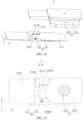
- a surface of the insulator 22 close to the second surface 216 of the adapter 21 has a stepped recess 220, a bottom wall of the stepped recess 220 is provided with an injection-molded necking portion 2200, and the height (as shown by H1 in FIG. 8 ) of the injection-molded necking portion 2200 is less than or equal to the depth (as shown by H2 in FIG. 8 ) of the stepped recess 220.
- a stepped recess 220 may be further provided in a surface of the insulator 22 close to the second surface 216 of the adapter 21 in the thickness direction Z of the adapter 21. It can be seen from the foregoings that the adapter 21 and the insulator 22 are prepared by an integral injection molding process, such that an injection-molded necking portion 2200 for injection molding is formed on the insulator 22.
- the injection-molded necking portion 2200 may be arranged on the bottom wall of the stepped recess 220, and the height of the injection-molded necking portion 2200 is less than or equal to the depth of the stepped recess 220, such that the overall thickness of the current collecting member 20 is reduced, which can ensure that the surface of the insulator 22 is flush, and the current collecting member 20 can be flush with and attached to a lower surface of the lower plastic part 11 when subsequently mounted on the lower plastic part 11.
- the ratio of the height H1 of the injection-molded necking portion 2200 to the depth H2 of the stepped recess 220 is greater than or equal to 1/10 and less than or equal to 9/10.
- a distance may be provided between a surface of the injection-molded necking portion 2200 that faces away from the bottom wall of the stepped recess 220 and a surface of the insulator 22 that is provided with the stepped recess 220.
- a top surface of the injection-molded necking portion 2200 is lower than an edge surface of the insulator 22 that is provided with the stepped recess 220, that is, the injection-molded necking portion 2200 is completely arranged inside the stepped recess 220 to prevent the injection-molded necking portion 2200 from protruding from the surface of the insulator 22 that is provided with the stepped recess 220, which can further reduce the overall thickness of the current collecting member 20.
- the ratio of the height H1 of the injection-molded necking portion 2200 to the depth H2 of the stepped recess 220 may be 0.1, 0.2, 0.3, 0.4, 0.5, 0.6, 0.7, 0.8, 0.9, etc.
- the height H1 of the injection-molded necking portion 2200 ranges from 0.06 mm to 0.31 mm.
- the height H1 of the injection-molded necking portion 2200 may be 0.06 mm, 0.08 mm, 0.1 mm, 0.12 mm, 0.15 mm, 0.18 mm, 0.2 mm, 0.25 mm, 0.26 mm, 0.27 mm, 0.28 mm, 0.29 mm, 0.3 mm, 0.31 mm, etc.
- multiple first recesses 2121 are provided in a surface of the transition 212 that faces the insulator 22.
- multiple first recesses 2121 may be further provided in a side surface of the transition 212 in the thickness direction Z. That is, multiple first recesses 2121 is provided in a surface of the transition 212 that faces the insulator 22. In other words, in this implementation, multiple first recesses 2121 may be provided in the first surface 215 of the transition 212. Since the first connecting portion 211 of the adapter 21 will be subsequently welded to the pole assembly 15, the second connecting portion 214 of the adapter 21 will be welded to the electrode assembly 30.
- the provision of the multiple first recesses 2121 may reduce reflections generated during laser welding, and thus reduce a reflection rate and improve the anti-reflection effect, thereby avoiding pseudo soldering or poor soldering caused by reflections, increasing a welding excellence rate, and improving the welding effect.
- the side surface of the insulator 22 provided with the stepped recess 220 may be brought closer to the lower surface of the lower plastic part 11, and the surface of the transition 212 provided with the multiple first recesses 2121 may be brought away from the lower surface of the lower plastic part 11. In this way, not only the current collecting member 20 can be flush with and attached to the lower plastic part 11, but also the reflection rate can be reduced and the welding effect can be improved.
- each first recess 2121 includes, but is not limited to, a square, a rectangle, a diamond, a circle, etc.
- the multiple first recesses 2121 are arranged in array.
- the surface of the insulator 22 close to the first surface 215 is provided with an extension 221, and multiple second recesses 2210 are provided in a surface of the extension 221 away from the transition 212.
- orthogonal projection planes of the multiple second recesses 2210 at least partially overlap with orthogonal projection planes of the multiple first recesses 2121.
- an extension 221 may be further arranged on the surface of the insulator 22 close to the first surface 215 of the adapter 21, and the extension 221 extends up to a position directly corresponding to the transition 212, thereby using the extension 221 to buffer and protect the transition 212, in order to prevent rigid contact between the transition 212 and other components and prevent damages to the transition 212. Furthermore, the arrangement of the extension 221 on a side of the adapter 21 can further reduce the amplitude of vibration of the transition 212, so as to prevent fractures of the adapter 21 caused by a relatively large amplitude of vibration of the transition 212 during use and transportation due to a relatively large length of the adapter 21, thereby increasing the structural strength of the adapter 21.
- multiple second recesses 2210 may be further provided in the surface of the extension 221 away from the transition 212.
- multiple second recesses 2210 may be provided in a lower surface of the extension 221.
- the orthogonal projection planes of the multiple second recesses 2210 at least partially overlap with the orthogonal projection planes of the multiple first recesses 2121.
- the anti-reflection effect may be further improved by the cooperation between the first recesses 2121 and the second recesses 2210, that is, by a double recess structure, further reducing the reflections generated during laser welding, and reducing the reflection rate. Pseudo soldering or poor soldering caused by reflections is further avoided, the welding excellence rate is increased, and the welding effect is improved.
- the orthogonal projection planes of the multiple second recesses 2210 partially overlap with the orthogonal projection planes of the multiple first recesses 2121, that is, the orthogonal projection planes of the multiple second recesses 2210 and the orthogonal projection planes of the multiple first recesses 2121 overlap only in some regions, and are staggered in the remaining regions.
- the orthogonal projection planes of the multiple second recesses 2210 completely overlap with the orthogonal projection planes of the multiple first recesses 2121, which can further improve the anti-reflection effect, increase the welding excellence rate and improve the welding effect.
- a larger overlapping region between the orthogonal projection planes of the multiple second recesses 2210 and the orthogonal projection planes of the multiple first recesses 2121 indicates a better anti-reflection effect.
- each second recess 2210 includes, but is not limited to, a square, a rectangle, a diamond, a circle, etc.
- the multiple second recesses 2210 are arranged in array.
- the second recesses 2210 and the first recesses 2121 are exactly the same in shape, size, number and arrangement.
- the third protective portion 228 includes a first covering portion 223.
- the first covering portion 223 is provided with a projection 2230 protruding in the length direction X of the adapter 21.
- the projection 2230 covers an end of the fuse portion 213 adjacent to the second connecting portion 214, and an end of the fuse portion 213 away from the second connecting portion 214 is exposed.
- the third protective portion 228 in this implementation may include a first covering portion 223, where the first covering portion 223 is provided with a projection 2230 protruding in the length direction X of the adapter 21.
- the projection 2230 may be arranged to protrude in a direction from the second connecting portion 214 to the first connecting portion 211, and the end of the fuse portion 213 adjacent to the second connecting portion 214 is covered by the projection 2230. It may also be understood that the projection 2230 covers the second surface 216 of the fuse portion 213.
- the projection 2230 of the first covering portion 223 covers part of the fuse portion 213, which may prevent the fuse portion 213 from fracturing due to contact and collision between the fuse portion 213 and other components, thereby effectively protecting the fuse portion 213, and increasing the structural strength of the adapter 21. Furthermore, the projection 2230 may be further used to cover some sharp edges of the fuse portion 213 in the width direction Y of the adapter 21, so as to further prevent the electrode assembly 30 from contact with and being cut by these sharp edges.
- the projection 2230 covers the end of the fuse portion 213 adjacent to the second connecting portion 214 and the end of the fuse portion 213 away from the second connecting portion 214 is exposed, in other words, the projection 2230 covers only part of the second surface 216 of the fuse portion 213, the rest of the second surface 216 of the fuse portion 213 is exposed, and thus other purposes may be achieved subsequently by using the second surface 216 of the fuse portion 213.
- the second surface 216 of the fuse portion 213 may be provided with an avoidance space, and the pole assembly 15 is avoided by means of this avoidance space.
- the third protective portion 228 further includes a second covering portion 224, the second covering portion 224 covering an end of the fuse portion 213 close to an edge of the adapter 21.
- the third protective portion 228 of this implementation may further include a second covering portion 224 in addition to the first covering portion 223.
- one or two second covering portions 224 may be provided.
- the two second covering portions 224 are arranged opposite to each other in the width direction Y of the adapter 21.
- the second covering portion 224 may be used to cover the end of the fuse portion 213 close to the edge of the adapter 21.
- the second covering portion may cooperate with the first covering portion 223 to cover the fuse portion 213 from different directions, thereby further preventing the fuse portion 213 from fracturing due to contact and collision between the fuse portion 213 and other components, effectively protecting the fuse portion 213, and increasing the structural strength of the adapter 21.
- the two second covering portions 224 arranged opposite to each other may also respectively cover the two sharp edges of the fuse portion 213, so as to further prevent the electrode assembly 30 from contact with and being cut by the sharp edges of the fuse portion.
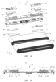
- the energy storage device 1 includes a housing 50 having an opening 501, the housing 50 being provided with an accommodating cavity 502; an electrode assembly 30 accommodated inside the accommodating cavity 502; an end cap assembly 10 covering the opening 501; a pole assembly 15 arranged in the end cap assembly 10, the pole assembly 15 including a flange 151; a lower plastic part 11 arranged between the electrode assembly 30 and the end cap assembly 10; and a current collecting member 20 provided in the above implementations of the present disclosure, where the current collecting member 20 is arranged on a side of the lower plastic part 11 away from the end cap assembly 10, the first connecting portion 211 of the current collecting member 20 is electrically connected to the pole assembly 15, and the second connecting portion 214 of the current collecting member 20 is electrically connected to the electrode assembly 30.
- the energy storage device 1 may include, but is not limited to, a battery cells, a battery module, a battery pack, a battery system, etc. When the energy storage device 1 is a battery cell, the energy storage device may be a square battery.
- the energy storage device 1 mainly includes an end cap assembly 10, a lower plastic part 11, a pole assembly 15, a current collecting member 20, an electrode assembly 30, and a housing 50.
- the end cap assembly 10 includes an upper rubber part 12, a top cap 13, a stress member 14, etc.
- the housing 50 has an accommodating cavity 502 for accommodating the electrode assembly 30, and the housing 50 also has an opening 501 communicating with the accommodating cavity 502.
- the top cap 13 is mounted on an upper surface of the lower plastic part 11, a through hole is provided in the top cap 13, and the stress member 14 is mounted in the through hole.
- the top cap 13 has a first mounting hole 130
- the lower plastic part 11 has a second mounting hole 113.
- the first mounting hole 130 and the second mounting hole 113 are arranged opposite to each other.
- the pole assembly 15 includes a flange 151 and a riveting portion 152, where the riveting portion 152 passes through the first mounting hole 130 and the second mounting hole 113, and the flange 151 is arranged on a side surface of the lower plastic part 11 that faces away from the top cap 13, that is, the flange 151 is located on a lower surface of the lower plastic part 11.
- the current collecting member 20 is arranged on a side of the lower plastic part 11 away from the end cap assembly 10.
- the first connecting portion 211 of the adapter 21 of the current collecting member 20 is electrically connected to the pole assembly 15, and the second connecting portion 214 of the adapter 21 of the current collecting member 20 is electrically connected to the electrode assembly 30. Therefore, the pole assembly 15 and the electrode assembly 30 may be connected together by means of the current collecting member 20, so as to facilitate transmission of currents.
- the peripheries of the first corners 2120 may be first covered by the first protective portion 226 of the insulator 22, such that the first corners 2120 are arranged in the first protective portion 226. Furthermore, the peripheries of the second corners 2140 is covered by the second protective portion 227 of the insulator 22, such that the second corners 2140 are arranged in the second protective portion 227.
- the electrode assembly 30 may be brought into contact with the first protective portion 226 on the peripheries of the first corners 2120 and the second protective portion 227 on the peripheries of the second corners 2140, thereby preventing the electrode assembly 30 from contact with the first corners 2120 and the second corners 2140 around the fuse portion 213, preventing the electrode assembly 30 from being cut by the first corners 2120 and the second corners 2140, and effectively protecting the electrode assembly 30.
- the insulator 22 may further include a third protective portion 228 in addition to the first protective portion 226 and the second protective portion 227.
- the third protective portion 228 is connected between the first protective portion 226 and the second protective portion 227, the third protective portion 228 covers the fuse portion 213 of the adapter 21, and the second surface 216 of the fuse portion 213 is partially exposed.
- the third protective portion 228 may further include the fuse portion 213 of the adapter 21, thereby providing a buffer for the fuse portion 213, effectively protecting the fuse portion 213, preventing the fuse portion 213 from fracturing due to the vibration of the current collecting member 20, and increasing the structural strength of the current collecting member 20.
- the third protective portion 228 may also cover sharp edges on each side of the fuse portion 213 to prevent the edges of the fuse portion 213 from cutting the electrode assembly 30, which not only effectively protects the energy storage device 1, but also improves the use safety and service life of the energy storage device 1.
- an avoidance recess 112 is provided in a surface of the lower plastic part 11 close to the current collecting member 20, and the insulator 22 is at least partially accommodated inside the avoidance recess 112.
- the current collecting member 20 located on the side of the lower plastic part 11 facing away from the top cap 13 may be connected to the pole assembly 15.
- the insulator 22 covers the fuse portion 213.
- the insulator 22 protrudes from the opposite sides of the adapter 21, and the thickness of the current collecting member 20 is the sum of the thickness of the adapter 21 and thicknesses of the insulator 22 located on the opposite sides of the adapter 21. It may also be understood that the thickness of the current collecting member 20 is the thicknesses of the insulators 22.
- an avoidance recess 112 may be provided in the side surface of the lower plastic part 11 close to the current collecting member 20, and the insulator 22 that is located on the side of the fuse portion 213 close to the lower plastic part 11 is at least partially fitted into the avoidance recess 112. It may also be understood that the insulator 22 is at least partially accommodated inside the avoidance recess 112.
- the avoidance recess 112 is provided in the lower surface of the lower plastic part 11 to avoid the insulator 22 that protrudes from the side of the adapter 21 close to the lower plastic part 11, such that the current collecting member 20 tends to be flush with the lower plastic part 11 when stacked and fitted with the lower plastic part, and the overall thickness of the lower plastic part 11 fitted with the current collecting member 20 is reduced.
- the lower plastic part 11 has a through hole 110 corresponding to the stress member 14, the lower plastic part 11 is also provided with a grid structure 111 for covering the through hole 110, the grid structure 111 is configured to divide the through hole 110 into multiple slots, and the avoidance recess 112 may be arranged around the periphery of the grid structure 111, thereby making the structure on the lower plastic part 11 more compact, and saving the space for the lower plastic part 11.
- the insulator 22 may be fitted with the grid structure 111 by providing the avoidance recess 112 around the periphery of the grid structure 111, so the insulator 22 may be used to protect the grid structure 111 and prevent damages of the grid structure 111 due to the vibration during use or transportation of the energy storage device 1.
- the shape of the avoidance recess 112 may be the same as that of the insulator 22 on the side of the fuse portion 213 close to the lower plastic part 11.
- the flange 151 may not be dimensioned to be too small in the length direction X of the energy storage device 1, otherwise the flange 151 and the current collecting member 20 may suffer from the problems of poor soldering and pseudo soldering.
- the flange 151 with such a large dimension can be closely fitted into the current collecting member 20.
- a stepped recess 220 is provided in the surface of the insulator 22 close to the second surface 216 of the adapter 21.
- the stepped recess 220 includes a first recess 2201 and a second recess 2202 that are arranged opposite to each other in the width direction Y of the adapter 21.
- the fuse portion 213 is arranged between the first recess 2201 and the second recess 2202.
- a side of the first recess 2201 close to the flange 151 and a side of the second recess 2202 close to the flange 151 define a connecting line L, and an end of the flange 151 adjacent to the fuse portion 213 extends beyond the connecting line L towards the insulator 22.
- a side of the flange 151 close to the insulator 22 extends beyond the connecting line L towards the insulator 22 by a distance D1 of 1.12-6.78 mm.
- the side of the flange 151 close to the insulator 22 extends beyond the connecting line L towards the insulator 22 by a distance D1 that may be 1.12 mm, 1.28 mm, 2.37 mm, 3.45 mm, 4.17 mm, 5.18 mm, 6.2 mm, 6.78 mm, etc.
- the pole assembly 15 may include a flange 151 and a riveting portion 152 that are connected to each other, where the flange 151 is located on the side surface of the lower plastic part 11 close to the current collecting member 20, the riveting portion 152 penetrates the lower plastic part 11 and the top cap 13 and is riveted to a pressing block, and the pressing block is mounted on the upper rubber part 12.
- the first connecting portion 211 of the adapter 21 may be welded to the flange 151 of the pole assembly 15 to achieve connection between the adapter 21 and the pole assembly 15. Since the insulator 22 covers the fuse portion 213 of the adapter 21, the insulator 22 is arranged on opposite sides of the fuse portion 213.
- the fuse portion 213 can be sandwiched between the first recess 2201 of the stepped recess 220 and the second recess 2202 of the stepped recess 220, and the second surface 216 of the fuse portion 213 is provided with an avoidance space 2130.
- the end of the flange 151 close to the fuse portion 213 may be located inside the avoidance space 2130, such that the current collecting member 20 is attached to the surface of the flange 151 in a flush manner, thereby saving the internal space of the energy storage device 1 and increasing energy density.
- avoidance space 2130 may also be understood as that the insulator 22 located on the second surface 216 of the fuse portion 213 is provided with an opening that forms the avoidance space 2130.
- the avoidance space 2130 is enclosed jointly by the first covering portion 223 of the third protective portion 228 of the insulator 22 located on the second surface 216 of the fuse portion 213, two second covering portions 224 and the fuse portion 213.
- this implementation provides a power consuming apparatus 100, including an energy storage device 1 provided in the above implementation of the present disclosure, the energy storage device 1 supplying power to the power consuming apparatus 100.
- the power consuming apparatus may be applied in the fields of vehicles, power storage stations, etc.
- the vehicle may be a fuel vehicle, a gas vehicle or a new energy vehicle.
- the new energy vehicle may be a battery electric vehicle, a hybrid electric vehicle, an extended-range vehicle, etc.
- the vehicle includes a battery, a controller, and a motor.
- the battery is configured to supply power to the controller and the motor as a power source for operating and driving the vehicle.
- the battery is configured to meet the operation power demands during starting, navigation, and traveling of the vehicle.
- the battery supplies power to the controller, the controller controls the battery to supply power to the motor, and the motor receives and uses the power from the battery as a power supply for driving the vehicle, replacing or partially replacing fuel or natural gas to provide driving power for the vehicle.
- the first protective portion may cover the first corners and the second protective portion may cover the second corners, in other words, the first corners are arranged in the first protective portion and the second corners are arranged in the second protective portion.
- the electrode assembly may be brought into contact with the first protective portion on the peripheries of the first corners and the second protective portion on the peripheries of the second corners, thereby preventing the electrode assembly from contact with the first corners and the second corners around the fuse portion, preventing the electrode assembly from being cut by the first corners and the second corners, and effectively protecting the electrode assembly.
- the third protective portion may cover the fuse portion of the adapter, thereby providing a buffer for the fuse portion, effectively protecting the fuse portion, preventing the fuse portion from fracturing due to the vibration of the current collecting member, and increasing the structural strength of the current collecting member.
- the third protective portion may also cover sharp edges on each side of the fuse portion to prevent the edges of the fuse portion from cutting the electrode assembly, which not only effectively protects the power consuming apparatus, but also improves the use safety and service life of the power consuming apparatus.
- mounting may be understood in a broad sense. For example, they may be fixed connection, detachable connection, or integral connection; may be mechanical connection or electrical connection; or may be direct connection, indirect connection by means of an intermediate member, or internal communication between two elements.
- connection may be understood in a broad sense. For example, they may be fixed connection, detachable connection, or integral connection; may be mechanical connection or electrical connection; or may be direct connection, indirect connection by means of an intermediate member, or internal communication between two elements.
Landscapes
- Chemical & Material Sciences (AREA)
- Chemical Kinetics & Catalysis (AREA)
- Electrochemistry (AREA)
- General Chemical & Material Sciences (AREA)
- Connection Of Batteries Or Terminals (AREA)
- Fuses (AREA)
Applications Claiming Priority (1)
| Application Number | Priority Date | Filing Date | Title |
|---|---|---|---|
| CN202310091078.8A CN115911775B (zh) | 2023-02-09 | 2023-02-09 | 集流构件、储能装置及用电设备 |
Publications (3)
| Publication Number | Publication Date |
|---|---|
| EP4415150A2 true EP4415150A2 (de) | 2024-08-14 |
| EP4415150A3 EP4415150A3 (de) | 2024-09-04 |
| EP4415150B1 EP4415150B1 (de) | 2026-01-28 |
Family
ID=85744748
Family Applications (1)
| Application Number | Title | Priority Date | Filing Date |
|---|---|---|---|
| EP23213229.0A Active EP4415150B1 (de) | 2023-02-09 | 2023-11-30 | Stromabnahmeelement, energiespeichervorrichtung und stromverbrauchende vorrichtung |
Country Status (3)
| Country | Link |
|---|---|
| US (1) | US11962045B1 (de) |
| EP (1) | EP4415150B1 (de) |
| CN (1) | CN115911775B (de) |
Families Citing this family (8)
| Publication number | Priority date | Publication date | Assignee | Title |
|---|---|---|---|---|
| WO2024243909A1 (zh) * | 2023-05-31 | 2024-12-05 | 深圳海辰储能控制技术有限公司 | 端盖组件、储能装置以及用电设备 |
| CN116365188B (zh) * | 2023-05-31 | 2023-08-18 | 深圳海辰储能控制技术有限公司 | 转接组件、储能装置和用电设备 |
| CN116365125B (zh) * | 2023-05-31 | 2023-08-08 | 深圳海辰储能控制技术有限公司 | 端盖组件、储能装置以及用电设备 |
| CN116365175B (zh) * | 2023-05-31 | 2023-07-28 | 深圳海辰储能控制技术有限公司 | 储能装置和用电设备 |
| WO2024243935A1 (zh) * | 2023-05-31 | 2024-12-05 | 深圳海辰储能控制技术有限公司 | 转接组件、储能装置和用电设备 |
| CN117878540B (zh) * | 2024-03-12 | 2024-11-01 | 蜂巢能源科技股份有限公司 | 连接片及电芯 |
| CN120109319B (zh) * | 2025-05-07 | 2025-08-12 | 江苏睿恩新能源科技有限公司 | 一种锂离子圆柱二次电池、用电装置 |
| CN120453644B (zh) * | 2025-07-11 | 2025-10-28 | 深圳海辰储能科技有限公司 | 端盖组件、储能装置和用电设备 |
Family Cites Families (16)
| Publication number | Priority date | Publication date | Assignee | Title |
|---|---|---|---|---|
| JP5105394B2 (ja) * | 2006-03-15 | 2012-12-26 | 日立ビークルエナジー株式会社 | 電池ユニット |
| JP5072796B2 (ja) * | 2008-05-23 | 2012-11-14 | ソニーケミカル&インフォメーションデバイス株式会社 | 保護素子及び二次電池装置 |
| JP6375610B2 (ja) | 2013-11-13 | 2018-08-22 | 株式会社Gsユアサ | 蓄電素子及びその製造方法 |
| CN205429058U (zh) * | 2016-03-18 | 2016-08-03 | 宁德时代新能源科技股份有限公司 | 二次电池 |
| KR102629053B1 (ko) * | 2016-08-08 | 2024-01-23 | 삼성에스디아이 주식회사 | 집전부재를 갖는 이차 전지 |
| CN209344143U (zh) * | 2018-12-28 | 2019-09-03 | 蜂巢能源科技有限公司 | 动力电池盖板 |
| CN209329018U (zh) | 2019-01-22 | 2019-08-30 | 中兴高能技术有限责任公司 | 一种电池的连接片组件和电池 |
| CN112310575B (zh) * | 2020-04-03 | 2022-11-29 | 宁德时代新能源科技股份有限公司 | 电池模块、电池组及使用二次电池的装置 |
| CN213717030U (zh) * | 2020-11-04 | 2021-07-16 | 东莞塔菲尔新能源科技有限公司 | 一种电池用的连接片、电池及电池模组 |
| CN112787047A (zh) * | 2021-01-29 | 2021-05-11 | 常州瑞德丰精密技术有限公司 | 转接片、二次电池及电池模组 |
| CN214280158U (zh) * | 2021-01-29 | 2021-09-24 | 常州瑞德丰精密技术有限公司 | 转接片、二次电池及电池模组 |
| CN214957272U (zh) * | 2021-04-23 | 2021-11-30 | 常州瑞德丰精密技术有限公司 | 二次电池的防脱落熔断结构 |
| CN215497006U (zh) * | 2021-06-23 | 2022-01-11 | 江西百思利新能源科技股份有限公司 | 二次电池顶盖及其二次电池 |
| CN217158580U (zh) * | 2022-03-24 | 2022-08-09 | 宁德时代新能源科技股份有限公司 | 集流构件、电池单体、电池及用电设备 |
| CN217903377U (zh) * | 2022-04-18 | 2022-11-25 | 宁德时代新能源科技股份有限公司 | 转接组件、电池单体、电池及用电装置 |
| CN218300161U (zh) * | 2022-08-10 | 2023-01-13 | 湖北亿纬动力有限公司 | 一种电池集流盘及电池 |
-
2023
- 2023-02-09 CN CN202310091078.8A patent/CN115911775B/zh active Active
- 2023-08-07 US US18/231,030 patent/US11962045B1/en active Active
- 2023-11-30 EP EP23213229.0A patent/EP4415150B1/de active Active
Also Published As
| Publication number | Publication date |
|---|---|
| CN115911775A (zh) | 2023-04-04 |
| EP4415150A3 (de) | 2024-09-04 |
| US11962045B1 (en) | 2024-04-16 |
| CN115911775B (zh) | 2023-05-16 |
| EP4415150B1 (de) | 2026-01-28 |
Similar Documents
| Publication | Publication Date | Title |
|---|---|---|
| EP4415150A2 (de) | Stromabnahmeelement, energiespeichervorrichtung und stromverbrauchende vorrichtung | |
| CN112072058B (zh) | 电池单体、电池、用电设备及电池制造方法 | |
| KR101821675B1 (ko) | 이차 전지 | |
| JP6599129B2 (ja) | 角形二次電池及びそれを用いた組電池、並びにその製造方法 | |
| KR20230024376A (ko) | 배터리 셀, 배터리, 전기 장치, 배터리의 제조 방법 | |
| EP4475327A1 (de) | Adapterplatte, batteriezelle, batterie und elektrische vorrichtung | |
| EP4518017A1 (de) | Adapterelement, batteriezelle, batterie und elektrische vorrichtung | |
| KR20230167395A (ko) | 배터리 셀, 배터리, 전기 장치 및 배터리 셀의 제조 방법과 장치 | |
| JPWO2016136248A1 (ja) | 電源装置及びこれを備える車両 | |
| EP4096012A1 (de) | Sammelschienenkomponente, batterie und elektrische vorrichtung | |
| CN211017134U (zh) | 顶盖组件、二次电池、电池模块以及装置 | |
| KR20190084765A (ko) | 전극 탭-리드 결합부에 적용된 플라스틱 부재를 포함하는 전극조립체 및 이를 포함하는 이차전지 | |
| JP2024112609A (ja) | 蓄電デバイス | |
| KR20240074831A (ko) | 전기셀, 전지 및 전기기기 | |
| JP6453567B2 (ja) | 二次電池 | |
| US12580254B2 (en) | Energy storage apparatus and electric device | |
| KR102742669B1 (ko) | 이차 전지 및 조전지 | |
| EP4415143B1 (de) | Energiespeichervorrichtung und elektrizitätsverbrauchsvorrichtung | |
| CN119542699A (zh) | 极柱、顶盖组件、电池单体、电池及用电装置 | |
| CN116345080A (zh) | 二次电池 | |
| HK40090996A (zh) | 集流构件、储能装置及用电设备 | |
| HK40090996B (zh) | 集流构件、储能装置及用电设备 | |
| CN224191056U (zh) | 顶盖组件、电池单体、电池及用电装置 | |
| CN223843141U (zh) | 极柱组件、盖板组件及电芯 | |
| CN222654302U (zh) | 电池单体、电池及用电设备 |
Legal Events
| Date | Code | Title | Description |
|---|---|---|---|
| PUAI | Public reference made under article 153(3) epc to a published international application that has entered the european phase |
Free format text: ORIGINAL CODE: 0009012 |
|
| STAA | Information on the status of an ep patent application or granted ep patent |
Free format text: STATUS: THE APPLICATION HAS BEEN PUBLISHED |
|
| PUAL | Search report despatched |
Free format text: ORIGINAL CODE: 0009013 |
|
| AK | Designated contracting states |
Kind code of ref document: A2 Designated state(s): AL AT BE BG CH CY CZ DE DK EE ES FI FR GB GR HR HU IE IS IT LI LT LU LV MC ME MK MT NL NO PL PT RO RS SE SI SK SM TR |
|
| AK | Designated contracting states |
Kind code of ref document: A3 Designated state(s): AL AT BE BG CH CY CZ DE DK EE ES FI FR GB GR HR HU IE IS IT LI LT LU LV MC ME MK MT NL NO PL PT RO RS SE SI SK SM TR |
|
| RIC1 | Information provided on ipc code assigned before grant |
Ipc: H01M 50/59 20210101ALI20240726BHEP Ipc: H01M 50/586 20210101ALI20240726BHEP Ipc: H01M 50/583 20210101ALI20240726BHEP Ipc: H01M 50/581 20210101ALI20240726BHEP Ipc: H01M 50/55 20210101ALI20240726BHEP Ipc: H01M 50/538 20210101ALI20240726BHEP Ipc: H01M 50/176 20210101ALI20240726BHEP Ipc: H01M 50/15 20210101ALI20240726BHEP Ipc: H01M 50/103 20210101ALI20240726BHEP Ipc: H01M 50/533 20210101AFI20240726BHEP |
|
| STAA | Information on the status of an ep patent application or granted ep patent |
Free format text: STATUS: REQUEST FOR EXAMINATION WAS MADE |
|
| 17P | Request for examination filed |
Effective date: 20241126 |
|
| RBV | Designated contracting states (corrected) |
Designated state(s): AL AT BE BG CH CY CZ DE DK EE ES FI FR GB GR HR HU IE IS IT LI LT LU LV MC ME MK MT NL NO PL PT RO RS SE SI SK SM TR |
|
| STAA | Information on the status of an ep patent application or granted ep patent |
Free format text: STATUS: EXAMINATION IS IN PROGRESS |
|
| 17Q | First examination report despatched |
Effective date: 20250317 |
|
| RAP1 | Party data changed (applicant data changed or rights of an application transferred) |
Owner name: HITHIUM TECH HK LIMITED |
|
| GRAP | Despatch of communication of intention to grant a patent |
Free format text: ORIGINAL CODE: EPIDOSNIGR1 |
|
| STAA | Information on the status of an ep patent application or granted ep patent |
Free format text: STATUS: GRANT OF PATENT IS INTENDED |
|
| INTG | Intention to grant announced |
Effective date: 20251013 |
|
| GRAS | Grant fee paid |
Free format text: ORIGINAL CODE: EPIDOSNIGR3 |
|
| GRAA | (expected) grant |
Free format text: ORIGINAL CODE: 0009210 |
|
| STAA | Information on the status of an ep patent application or granted ep patent |
Free format text: STATUS: THE PATENT HAS BEEN GRANTED |
|
| AK | Designated contracting states |
Kind code of ref document: B1 Designated state(s): AL AT BE BG CH CY CZ DE DK EE ES FI FR GB GR HR HU IE IS IT LI LT LU LV MC ME MK MT NL NO PL PT RO RS SE SI SK SM TR |
|
| REG | Reference to a national code |
Ref country code: CH Ref legal event code: F10 Free format text: ST27 STATUS EVENT CODE: U-0-0-F10-F00 (AS PROVIDED BY THE NATIONAL OFFICE) Effective date: 20260128 Ref country code: GB Ref legal event code: FG4D |
|
| REG | Reference to a national code |
Ref country code: DE Ref legal event code: R096 Ref document number: 602023011261 Country of ref document: DE |
|
| REG | Reference to a national code |
Ref country code: IE Ref legal event code: FG4D |
|
| REG | Reference to a national code |
Ref country code: NL Ref legal event code: FP |