EP4414152B1 - Formmaterial mit kohlenstofffasern und glasfasern und verfahren zur herstellung eines formkörpers durch kaltpressen davon - Google Patents
Formmaterial mit kohlenstofffasern und glasfasern und verfahren zur herstellung eines formkörpers durch kaltpressen davon Download PDFInfo
- Publication number
- EP4414152B1 EP4414152B1 EP22878405.4A EP22878405A EP4414152B1 EP 4414152 B1 EP4414152 B1 EP 4414152B1 EP 22878405 A EP22878405 A EP 22878405A EP 4414152 B1 EP4414152 B1 EP 4414152B1
- Authority
- EP
- European Patent Office
- Prior art keywords
- layer
- molding material
- molded body
- fibers
- carbon fibers
- Prior art date
- Legal status (The legal status is an assumption and is not a legal conclusion. Google has not performed a legal analysis and makes no representation as to the accuracy of the status listed.)
- Active
Links
Images







Classifications
-
- B—PERFORMING OPERATIONS; TRANSPORTING
- B29—WORKING OF PLASTICS; WORKING OF SUBSTANCES IN A PLASTIC STATE IN GENERAL
- B29C—SHAPING OR JOINING OF PLASTICS; SHAPING OF MATERIAL IN A PLASTIC STATE, NOT OTHERWISE PROVIDED FOR; AFTER-TREATMENT OF THE SHAPED PRODUCTS, e.g. REPAIRING
- B29C43/00—Compression moulding, i.e. applying external pressure to flow the moulding material; Apparatus therefor
- B29C43/003—Compression moulding, i.e. applying external pressure to flow the moulding material; Apparatus therefor characterised by the choice of material
-
- B—PERFORMING OPERATIONS; TRANSPORTING
- B29—WORKING OF PLASTICS; WORKING OF SUBSTANCES IN A PLASTIC STATE IN GENERAL
- B29C—SHAPING OR JOINING OF PLASTICS; SHAPING OF MATERIAL IN A PLASTIC STATE, NOT OTHERWISE PROVIDED FOR; AFTER-TREATMENT OF THE SHAPED PRODUCTS, e.g. REPAIRING
- B29C70/00—Shaping composites, i.e. plastics material comprising reinforcements, fillers or preformed parts, e.g. inserts
- B29C70/04—Shaping composites, i.e. plastics material comprising reinforcements, fillers or preformed parts, e.g. inserts comprising reinforcements only, e.g. self-reinforcing plastics
- B29C70/06—Fibrous reinforcements only
- B29C70/10—Fibrous reinforcements only characterised by the structure of fibrous reinforcements, e.g. hollow fibres
-
- B—PERFORMING OPERATIONS; TRANSPORTING
- B29—WORKING OF PLASTICS; WORKING OF SUBSTANCES IN A PLASTIC STATE IN GENERAL
- B29B—PREPARATION OR PRETREATMENT OF THE MATERIAL TO BE SHAPED; MAKING GRANULES OR PREFORMS; RECOVERY OF PLASTICS OR OTHER CONSTITUENTS OF WASTE MATERIAL CONTAINING PLASTICS
- B29B11/00—Making preforms
- B29B11/14—Making preforms characterised by structure or composition
- B29B11/16—Making preforms characterised by structure or composition comprising fillers or reinforcement
-
- B—PERFORMING OPERATIONS; TRANSPORTING
- B29—WORKING OF PLASTICS; WORKING OF SUBSTANCES IN A PLASTIC STATE IN GENERAL
- B29C—SHAPING OR JOINING OF PLASTICS; SHAPING OF MATERIAL IN A PLASTIC STATE, NOT OTHERWISE PROVIDED FOR; AFTER-TREATMENT OF THE SHAPED PRODUCTS, e.g. REPAIRING
- B29C70/00—Shaping composites, i.e. plastics material comprising reinforcements, fillers or preformed parts, e.g. inserts
- B29C70/04—Shaping composites, i.e. plastics material comprising reinforcements, fillers or preformed parts, e.g. inserts comprising reinforcements only, e.g. self-reinforcing plastics
- B29C70/06—Fibrous reinforcements only
- B29C70/08—Fibrous reinforcements only comprising combinations of different forms of fibrous reinforcements incorporated in matrix material, forming one or more layers, and with or without non-reinforced layers
-
- B—PERFORMING OPERATIONS; TRANSPORTING
- B29—WORKING OF PLASTICS; WORKING OF SUBSTANCES IN A PLASTIC STATE IN GENERAL
- B29C—SHAPING OR JOINING OF PLASTICS; SHAPING OF MATERIAL IN A PLASTIC STATE, NOT OTHERWISE PROVIDED FOR; AFTER-TREATMENT OF THE SHAPED PRODUCTS, e.g. REPAIRING
- B29C70/00—Shaping composites, i.e. plastics material comprising reinforcements, fillers or preformed parts, e.g. inserts
- B29C70/04—Shaping composites, i.e. plastics material comprising reinforcements, fillers or preformed parts, e.g. inserts comprising reinforcements only, e.g. self-reinforcing plastics
- B29C70/06—Fibrous reinforcements only
- B29C70/10—Fibrous reinforcements only characterised by the structure of fibrous reinforcements, e.g. hollow fibres
- B29C70/12—Fibrous reinforcements only characterised by the structure of fibrous reinforcements, e.g. hollow fibres using fibres of short length, e.g. in the form of a mat
-
- B—PERFORMING OPERATIONS; TRANSPORTING
- B29—WORKING OF PLASTICS; WORKING OF SUBSTANCES IN A PLASTIC STATE IN GENERAL
- B29C—SHAPING OR JOINING OF PLASTICS; SHAPING OF MATERIAL IN A PLASTIC STATE, NOT OTHERWISE PROVIDED FOR; AFTER-TREATMENT OF THE SHAPED PRODUCTS, e.g. REPAIRING
- B29C70/00—Shaping composites, i.e. plastics material comprising reinforcements, fillers or preformed parts, e.g. inserts
- B29C70/04—Shaping composites, i.e. plastics material comprising reinforcements, fillers or preformed parts, e.g. inserts comprising reinforcements only, e.g. self-reinforcing plastics
- B29C70/28—Shaping operations therefor
- B29C70/30—Shaping by lay-up, i.e. applying fibres, tape or broadsheet on a mould, former or core; Shaping by spray-up, i.e. spraying of fibres on a mould, former or core
- B29C70/34—Shaping by lay-up, i.e. applying fibres, tape or broadsheet on a mould, former or core; Shaping by spray-up, i.e. spraying of fibres on a mould, former or core and shaping or impregnating by compression, i.e. combined with compressing after the lay-up operation
-
- B—PERFORMING OPERATIONS; TRANSPORTING
- B29—WORKING OF PLASTICS; WORKING OF SUBSTANCES IN A PLASTIC STATE IN GENERAL
- B29C—SHAPING OR JOINING OF PLASTICS; SHAPING OF MATERIAL IN A PLASTIC STATE, NOT OTHERWISE PROVIDED FOR; AFTER-TREATMENT OF THE SHAPED PRODUCTS, e.g. REPAIRING
- B29C70/00—Shaping composites, i.e. plastics material comprising reinforcements, fillers or preformed parts, e.g. inserts
- B29C70/04—Shaping composites, i.e. plastics material comprising reinforcements, fillers or preformed parts, e.g. inserts comprising reinforcements only, e.g. self-reinforcing plastics
- B29C70/28—Shaping operations therefor
- B29C70/30—Shaping by lay-up, i.e. applying fibres, tape or broadsheet on a mould, former or core; Shaping by spray-up, i.e. spraying of fibres on a mould, former or core
- B29C70/34—Shaping by lay-up, i.e. applying fibres, tape or broadsheet on a mould, former or core; Shaping by spray-up, i.e. spraying of fibres on a mould, former or core and shaping or impregnating by compression, i.e. combined with compressing after the lay-up operation
- B29C70/345—Shaping by lay-up, i.e. applying fibres, tape or broadsheet on a mould, former or core; Shaping by spray-up, i.e. spraying of fibres on a mould, former or core and shaping or impregnating by compression, i.e. combined with compressing after the lay-up operation using matched moulds
-
- B—PERFORMING OPERATIONS; TRANSPORTING
- B29—WORKING OF PLASTICS; WORKING OF SUBSTANCES IN A PLASTIC STATE IN GENERAL
- B29C—SHAPING OR JOINING OF PLASTICS; SHAPING OF MATERIAL IN A PLASTIC STATE, NOT OTHERWISE PROVIDED FOR; AFTER-TREATMENT OF THE SHAPED PRODUCTS, e.g. REPAIRING
- B29C70/00—Shaping composites, i.e. plastics material comprising reinforcements, fillers or preformed parts, e.g. inserts
- B29C70/04—Shaping composites, i.e. plastics material comprising reinforcements, fillers or preformed parts, e.g. inserts comprising reinforcements only, e.g. self-reinforcing plastics
- B29C70/28—Shaping operations therefor
- B29C70/40—Shaping or impregnating by compression not applied
- B29C70/42—Shaping or impregnating by compression not applied for producing articles of definite length, i.e. discrete articles
- B29C70/46—Shaping or impregnating by compression not applied for producing articles of definite length, i.e. discrete articles using matched moulds, e.g. for deforming sheet moulding compounds [SMC] or prepregs
-
- B—PERFORMING OPERATIONS; TRANSPORTING
- B32—LAYERED PRODUCTS
- B32B—LAYERED PRODUCTS, i.e. PRODUCTS BUILT-UP OF STRATA OF FLAT OR NON-FLAT, e.g. CELLULAR OR HONEYCOMB, FORM
- B32B5/00—Layered products characterised by the non- homogeneity or physical structure, i.e. comprising a fibrous, filamentary, particulate or foam layer; Layered products characterised by having a layer differing constitutionally or physically in different parts
- B32B5/22—Layered products characterised by the non- homogeneity or physical structure, i.e. comprising a fibrous, filamentary, particulate or foam layer; Layered products characterised by having a layer differing constitutionally or physically in different parts characterised by the presence of two or more layers which are next to each other and are fibrous, filamentary, formed of particles or foamed
- B32B5/24—Layered products characterised by the non- homogeneity or physical structure, i.e. comprising a fibrous, filamentary, particulate or foam layer; Layered products characterised by having a layer differing constitutionally or physically in different parts characterised by the presence of two or more layers which are next to each other and are fibrous, filamentary, formed of particles or foamed one layer being a fibrous or filamentary layer
- B32B5/26—Layered products characterised by the non- homogeneity or physical structure, i.e. comprising a fibrous, filamentary, particulate or foam layer; Layered products characterised by having a layer differing constitutionally or physically in different parts characterised by the presence of two or more layers which are next to each other and are fibrous, filamentary, formed of particles or foamed one layer being a fibrous or filamentary layer another layer next to it also being fibrous or filamentary
-
- D—TEXTILES; PAPER
- D04—BRAIDING; LACE-MAKING; KNITTING; TRIMMINGS; NON-WOVEN FABRICS
- D04H—MAKING TEXTILE FABRICS, e.g. FROM FIBRES OR FILAMENTARY MATERIAL; FABRICS MADE BY SUCH PROCESSES OR APPARATUS, e.g. FELTS, NON-WOVEN FABRICS; COTTON-WOOL; WADDING ; NON-WOVEN FABRICS FROM STAPLE FIBRES, FILAMENTS OR YARNS, BONDED WITH AT LEAST ONE WEB-LIKE MATERIAL DURING THEIR CONSOLIDATION
- D04H1/00—Non-woven fabrics formed wholly or mainly of staple fibres or like relatively short fibres
- D04H1/40—Non-woven fabrics formed wholly or mainly of staple fibres or like relatively short fibres from fleeces or layers composed of fibres without existing or potential cohesive properties
- D04H1/42—Non-woven fabrics formed wholly or mainly of staple fibres or like relatively short fibres from fleeces or layers composed of fibres without existing or potential cohesive properties characterised by the use of certain kinds of fibres insofar as this use has no preponderant influence on the consolidation of the fleece
- D04H1/4209—Inorganic fibres
- D04H1/4218—Glass fibres
-
- D—TEXTILES; PAPER
- D04—BRAIDING; LACE-MAKING; KNITTING; TRIMMINGS; NON-WOVEN FABRICS
- D04H—MAKING TEXTILE FABRICS, e.g. FROM FIBRES OR FILAMENTARY MATERIAL; FABRICS MADE BY SUCH PROCESSES OR APPARATUS, e.g. FELTS, NON-WOVEN FABRICS; COTTON-WOOL; WADDING ; NON-WOVEN FABRICS FROM STAPLE FIBRES, FILAMENTS OR YARNS, BONDED WITH AT LEAST ONE WEB-LIKE MATERIAL DURING THEIR CONSOLIDATION
- D04H1/00—Non-woven fabrics formed wholly or mainly of staple fibres or like relatively short fibres
- D04H1/40—Non-woven fabrics formed wholly or mainly of staple fibres or like relatively short fibres from fleeces or layers composed of fibres without existing or potential cohesive properties
- D04H1/42—Non-woven fabrics formed wholly or mainly of staple fibres or like relatively short fibres from fleeces or layers composed of fibres without existing or potential cohesive properties characterised by the use of certain kinds of fibres insofar as this use has no preponderant influence on the consolidation of the fleece
- D04H1/4209—Inorganic fibres
- D04H1/4242—Carbon fibres
-
- D—TEXTILES; PAPER
- D04—BRAIDING; LACE-MAKING; KNITTING; TRIMMINGS; NON-WOVEN FABRICS
- D04H—MAKING TEXTILE FABRICS, e.g. FROM FIBRES OR FILAMENTARY MATERIAL; FABRICS MADE BY SUCH PROCESSES OR APPARATUS, e.g. FELTS, NON-WOVEN FABRICS; COTTON-WOOL; WADDING ; NON-WOVEN FABRICS FROM STAPLE FIBRES, FILAMENTS OR YARNS, BONDED WITH AT LEAST ONE WEB-LIKE MATERIAL DURING THEIR CONSOLIDATION
- D04H1/00—Non-woven fabrics formed wholly or mainly of staple fibres or like relatively short fibres
- D04H1/40—Non-woven fabrics formed wholly or mainly of staple fibres or like relatively short fibres from fleeces or layers composed of fibres without existing or potential cohesive properties
- D04H1/58—Non-woven fabrics formed wholly or mainly of staple fibres or like relatively short fibres from fleeces or layers composed of fibres without existing or potential cohesive properties by applying, incorporating or activating chemical or thermoplastic bonding agents, e.g. adhesives
- D04H1/593—Non-woven fabrics formed wholly or mainly of staple fibres or like relatively short fibres from fleeces or layers composed of fibres without existing or potential cohesive properties by applying, incorporating or activating chemical or thermoplastic bonding agents, e.g. adhesives to layered webs
-
- D—TEXTILES; PAPER
- D04—BRAIDING; LACE-MAKING; KNITTING; TRIMMINGS; NON-WOVEN FABRICS
- D04H—MAKING TEXTILE FABRICS, e.g. FROM FIBRES OR FILAMENTARY MATERIAL; FABRICS MADE BY SUCH PROCESSES OR APPARATUS, e.g. FELTS, NON-WOVEN FABRICS; COTTON-WOOL; WADDING ; NON-WOVEN FABRICS FROM STAPLE FIBRES, FILAMENTS OR YARNS, BONDED WITH AT LEAST ONE WEB-LIKE MATERIAL DURING THEIR CONSOLIDATION
- D04H1/00—Non-woven fabrics formed wholly or mainly of staple fibres or like relatively short fibres
- D04H1/70—Non-woven fabrics formed wholly or mainly of staple fibres or like relatively short fibres characterised by the method of forming fleeces or layers, e.g. reorientation of fibres
- D04H1/72—Non-woven fabrics formed wholly or mainly of staple fibres or like relatively short fibres characterised by the method of forming fleeces or layers, e.g. reorientation of fibres the fibres being randomly arranged
-
- B—PERFORMING OPERATIONS; TRANSPORTING
- B29—WORKING OF PLASTICS; WORKING OF SUBSTANCES IN A PLASTIC STATE IN GENERAL
- B29C—SHAPING OR JOINING OF PLASTICS; SHAPING OF MATERIAL IN A PLASTIC STATE, NOT OTHERWISE PROVIDED FOR; AFTER-TREATMENT OF THE SHAPED PRODUCTS, e.g. REPAIRING
- B29C43/00—Compression moulding, i.e. applying external pressure to flow the moulding material; Apparatus therefor
- B29C43/02—Compression moulding, i.e. applying external pressure to flow the moulding material; Apparatus therefor of articles of definite length, i.e. discrete articles
- B29C43/20—Making multilayered or multicoloured articles
- B29C43/203—Making multilayered articles
-
- B—PERFORMING OPERATIONS; TRANSPORTING
- B29—WORKING OF PLASTICS; WORKING OF SUBSTANCES IN A PLASTIC STATE IN GENERAL
- B29K—INDEXING SCHEME ASSOCIATED WITH SUBCLASSES B29B, B29C OR B29D, RELATING TO MOULDING MATERIALS OR TO MATERIALS FOR MOULDS, REINFORCEMENTS, FILLERS OR PREFORMED PARTS, e.g. INSERTS
- B29K2307/00—Use of elements other than metals as reinforcement
- B29K2307/04—Carbon
-
- B—PERFORMING OPERATIONS; TRANSPORTING
- B29—WORKING OF PLASTICS; WORKING OF SUBSTANCES IN A PLASTIC STATE IN GENERAL
- B29K—INDEXING SCHEME ASSOCIATED WITH SUBCLASSES B29B, B29C OR B29D, RELATING TO MOULDING MATERIALS OR TO MATERIALS FOR MOULDS, REINFORCEMENTS, FILLERS OR PREFORMED PARTS, e.g. INSERTS
- B29K2995/00—Properties of moulding materials, reinforcements, fillers, preformed parts or moulds
- B29K2995/0037—Other properties
- B29K2995/0089—Impact strength or toughness
Definitions
- the present invention relates to a molding material X containing carbon fibers, glass fibers and a matrix resin, the molding material X having a specific shrinkage. Further, the present invention relates to a method of manufacturing a molded body by laminating the molding material X and a molding material Y having a specific shrinkage ratio and cold-pressing the laminated material X.
- Patent Literature 1 discloses a molding material in which glass fibers and carbon fibers are mixed, and Patent Literature 1 aims to exhibit physical properties equivalent to those of a molding material (SMC, sheet molding compound) composed of a mixed product of glass fibers and carbon fibers made of only carbon fibers.
- SMC sheet molding compound
- Patent Literatures 1 and 2 describe a molded body formed by laminating and molding a thermoplastic resin layer reinforced by glass fibers and a thermoplastic resin reinforced with carbon fibers.
- Patent Literatures 3 and 4 describe a wave impact absorbing member using a thermoplastic resin reinforced with carbon fibers.
- Patent Literature 6 discloses a method for producing a molded body.
- Patent Literature 1 is an invention intending to mix carbon fibers and glass fibers and exhibit the same physical properties as an SMC composed only of carbon fibers even at low cost, and a problem of warpage when a molding material is laminated and press-molded has not been studied at all.
- Patent Literature 2 since the material described in Patent Literature 2 has a laminated structure in which a glass fiber composite material is sandwiched by carbon fiber composite materials, a composite material containing only carbon fibers is disposed in both surface layers. In this case, since the fracture strain of the carbon fiber composite material in both surface layers is small, the layer on the side opposite to the impact receiving side is fractured when subjected to an impact, and cracks are easily generated. Although the glass fiber composite material present in a central layer has a large fracture strain, the glass fiber composite material present in the inside of the molded body does not contribute to prevention of cracks when the molded body is subjected to an impact.
- an object of the present invention is to provide a method for producing a molded body by which high impact resistance of the molded body is satisfied and the problem of "warpage" of the molded body is solved.
- the present invention provides the following means.
- a molded body with little warpage even when molded using a molding material containing discontinuous carbon fibers and discontinuous glass fibers can be provided.
- carbon fiber Cx and the carbon fiber Cy are collectively simply referred to as "carbon fiber”.
- carbon fibers for use in the present invention polyacrylonitrile (PAN)-based carbon fibers, petroleum/coal pitch-based carbon fibers, rayon-based carbon fibers, cellulose-based carbon fibers, lignin-based carbon fibers, phenol-based carbon fibers, and the like are generally known. In the present invention, any of these carbon fibers can be preferably used. Among these, in the present invention, it is preferable to use polyacrylonitrile (PAN)-based carbon fibers because of excellent tensile strength thereof.
- PAN polyacrylonitrile
- the fiber diameter of the carbon fiber monofilament (generally, the monofilament may be called a filament) used in the present invention may be appropriately determined according to the type of carbon fiber, and is not particularly limited.
- the average fiber diameter is generally preferably in the range of 3 ⁇ m to 50 ⁇ m, more preferably in the range of 4 ⁇ m to 12 ⁇ m, even more preferably in the range of 5 ⁇ m to 8 ⁇ m.
- the average fiber diameter is not the diameter of the fiber bundle, and refers to the average of the diameters of the single fibers of the carbon fibers constituting the fiber bundle.
- the average fiber diameter of carbon fibers can be measured, for example, by the method described in JIS R-7607:2000.
- the glass fiber Gx and the glass fiber Gy are simply referred to as "glass fibers".
- the type of glass fibers used in the present invention is not particularly limited, and a glass fiber made of any of E glass, A glass, or C glass can be used, or a mixture thereof can be used.
- the glass fiber in the present invention is not particularly limited, but an average fiber diameter of the glass fibers is preferably 1 ⁇ m to 50 ⁇ m, and more preferably 5 ⁇ m to 20 ⁇ m.
- the average fiber diameter refers to the average of the diameters of the filaments constituting the strands, rather than the diameter of the strands.
- the glass fibers may be single-ended roving or multi-end roving.
- the carbon fiber or glass fiber used in the present invention may have a sizing agent adhered to the surface thereof.
- the type of the sizing agent can be appropriately selected according to the types of the carbon fiber or the glass fiber and the matrix resin, and is not particularly limited.
- the carbon fiber is preferably a discontinuous fiber, and a weight average fiber length thereof is preferably 1 mm or more and 100 mm or less.
- the glass fiber is preferably a discontinuous fiber, and a weight average fiber length thereof is preferably 1 mm or more and 100 mm or less.
- the fiber is preferably a continuous fiber, but the above range of the weight average fiber length is preferable from the viewpoint of improving formability.
- the glass fiber and/or the carbon fiber are collectively referred to as the "reinforcing fiber".
- the reinforcing fibers are at least one of glass fibers and carbon fibers. Reinforcing fibers may also refer to both carbon fibers and glass fibers.
- reinforcing fibers having different fiber lengths may be used in combination.
- the reinforcing fiber may have a single peak at the weight average fiber length, or may have a plurality of peaks.
- An average fiber length of the reinforcing fibers can be determined, for example, by measuring the fiber lengths of 100 fibers randomly extracted from the molded body in 1 mm increment using a caliper or the like based on the following formula (a).
- the average fiber length may be calculated by weight average fiber length (Lw).
- the matrix resin Mx contained in the molding material X and the matrix resin My contained in the molding material Y in the present invention may be thermosetting or thermoplastic, but are preferably a thermoplastic matrix resin. It is preferable that the matrix resin Mx and the matrix resin My are the same type of resin.
- the taken-out carbon fibers Cx are divided into: carbon fiber Cx1 (fiber width of less than 0.3 mm); carbon fiber Cx2 (fiber width of 0.3 mm or more and 3.0 mm or less); and carbon fiber Cx3 (fiber width of more than 3.0 mm), and weights of the carbon fiber Cx1, the carbon fiber Cx2 and the carbon fiber Cx3 are measured with a balance that can measure weight in 1/1000 mg increment. Based on the measured weight, the volume ratios of the carbon fiber Cx1, the carbon fiber Cx2, and the carbon fiber Cx3 are obtained by the formulas (d-1), (d-2), and (d-3) using the density ( ⁇ cf) of the reinforcing fiber.
- a degree of the two-dimensional random orientation is evaluated by determining a ratio of tensile moduli in two directions orthogonal to each other.
- a ratio (E ⁇ ) obtained by dividing a larger value by a smaller value of the values of the tensile elastic moduli measured in any direction and in a direction orthogonal to the any direction of the molded body is 5 or less, more preferably 2 or less, and still more preferably 1.5 or less, it can be evaluated that the glass fibers Gx are dispersed two-dimensionally and randomly.
- the molded body Since the molded body has a three-dimensional shape, as a method of evaluating two-dimensional random distribution in an in-plane direction, it is preferable to heat the molded body to a softening temperature or higher to return the molded body to a flat plate shape and solidify the molded body. After that, when the test piece is cut out from the molded body returned to the flat plate shape and the tensile elastic modulus is obtained, a random distribution state in a two-dimensional direction can be confirmed.
- a volume ratio of the carbon fiber Cx/the glass fiber Gx is 0.1 or more and 1.5 or less.
- the volume ratio is preferably 0.1 or more and 1.0 or less, more preferably 0.2 or more and 0.8 or less, and still more preferably 0.3 or more and 0.6 or less.
- the volume ratio of the carbon fiber Cx/the glass fiber Gx is 0.1 or more, warpage when combined with the molding material Y can be reduced, and when the volume ratio is 1.5 or less, impact resistance can be kept high in the same configuration.
- the volume ratio of the carbon fiber Cx/the glass fiber Gx is the ratio of the carbon fiber Cx to the glass fiber Gx.
- the weight average fiber length of the reinforcing fibers contained in the molding material X is more preferably 5 mm or more and 100 mm or less, still more preferably 5 mm or more and 80 mm or less, and yet still more preferably 10 mm or more and 60 mm or less.
- the weight average fiber length of the reinforcing fibers is 100 mm or less, the fluidity of the molding material X is improved, and a desired molded body shape is easily obtained when cold pressing is performed.
- the weight average fiber length is 1 mm or more, the mechanical strength of the molded body is likely to be improved.
- the carbon fiber Cx and the glass fiber Gx may be mixed in the same layer Xm.
- the same layer refers to a layer connected in a plane shape, and carbon fibers Cx and glass fibers Gx overlap in the same layer.
- the same layer can be formed by simultaneously applying the carbon fiber Cx and the glass fiber Gx.
- the molding material X is a single layer, and the carbon fiber Cx and the glass fiber Gx are mixed in the single layer.
- the lamination step can be omitted.
- the molding material X is a laminated body Px in which the layer Xc and the layer Xg are laminated, and the layer Xc contains the carbon fiber Cx and the layer Xg contains the glass fiber Gx.
- the lamination configuration is not particularly limited, and examples thereof include the following lamination configuration.
- the laminated body Px has an odd-numbered layer in which the layer Xc and the layer Xg are combined, and even more preferably has a three-layer, five-layer, or seven-layer configuration.
- the total of the number of layers Xc and Xg is an odd number (layer configuration is symmetry), warpage of the molding material X alone can be prevented.
- the molded body is an impact-resistant member, and is located on a side opposite to a side where the molding material X receives an impact when the molded body is formed.
- the molded body is formed, it is more preferable that at least one outermost layer is the layer Xg. It is even more preferable that the layer Xg is present in a surface layer opposite to the side to be subjected to the impact. With this configuration, when the molded body in the present invention is subjected to an impact, the tensile elongation can be increased in the surface layer opposite to the impact receiving side.
- the impact resistance can be improved by increasing the tensile fracture elongation of the opposite surface.
- the layer containing the glass fibers having a large fracture strain in the surface layer opposite to the side to be subjected to the impact cracks are less likely to be generated on the surface layer opposite to the side to be subjected to the impact. More specifically, since the volume content of the carbon fibers is equal to or less than the volume content of the glass fibers in the surface layer opposite to the side to be subjected to the impact, the fracture strain of this layer is improved, the impact resistance is improved, and cracks are less likely to be generated.
- the fracture strain of the glass fibers contained in the single layer is large.
- the molding material X is the laminated body Px and the layer Xg is in the outermost layer, the fracture strain of the glass fibers contained in the layer Xg is large.
- Example 1 when subjected to an impact, cracks are easily generated because the surface layer opposite to the impact receiving side is a carbon fiber composite material.
- Example 2 since the carbon fiber is not contained in the surface layer contributing to the rigidity, the molded body does not have a sufficient rigidity. When the carbon fiber and the resin are present only in the central layer, the carbon fiber and the resin layer hardly contribute to ensuring the rigidity of the molded body.
- a method for producing a molded body of the present invention is a method for producing a molded body by cold-pressing a molding material X and a molding material Y by laminating the molding material X and the molding material Y, in which the molding material Y includes discontinuous carbon fibers Cy and/or glass fibers Gy, and a matrix resin Ry.
- the molding material Y may preferably be a carbon fiber reinforced thermoplastic resin molding material containing discontinuous carbon fibers Cy and a matrix resin Ry, and in this case, it is preferably a single-layer carbon fiber reinforced thermoplastic resin molding material.
- a laminated body Py which will be described later, may be used as the molding material Y.
- the molding material Y is a laminated body Py in which the layer Yc and the layer Ycg are laminated, in which the layer Yc contains discontinuous carbon fibers Cyc, and the layer Ycg contains carbon fibers Cycg and/or glass fibers Gy.
- the molding material Y preferably contains carbon fibers Cy and glass fibers Gy.
- the lamination configuration is not particularly limited, and examples thereof include the following lamination configuration.
- the laminated body Py preferably has a three-layer structure of layer Yc/layer Ycg/layer Yc.
- the molded body When the molded body is formed, it is more preferable that at least one outermost layer is the layer Yc. It is more preferable that the molded body is an impact-resistant member, and the molding material Y is on a side that receives an impact. It is even more preferable that the molded body is an impact-resistant member, and the layer Yc is a side to be subjected to an impact.
- the layer Yc contains carbon fibers, the appearance is beautiful, and when the layer Yc is present on the surface, the appeal to the customer is high. In particular, when the outermost layer Yc to be a design surface has a grain, the design property is exceptional.
- the carbon fibers contained in the layer Yc are preferably randomly dispersed in a two-dimensional direction in the plane.
- the layer Yc randomly dispersed in the two-dimensional direction as the outermost layer, the bending rigidity can be increased.
- the carbon fibers contained in the layer Yc are defined as carbon fibers Cyc.
- the carbon fiber Cyc contains a carbon fiber Cyc1 having a fiber width of less than 0.3 mm and a carbon fiber Cyc2 having a fiber width of 0.3 mm or more and 3.0 mm or less, and a volume ratio of the carbon fiber Cyc2 to the carbon fiber Cyc is preferably 10 Vol% or more and less than 99 Vol%.
- the volume ratio of the carbon fibers Cyc2 is preferably 50 vol% or more and less than 99 vol%, and more preferably 70 vol% or more and less than 99 vol%.
- the fiber width and the volume ratio of the carbon fiber Cyc can be measured in the same manner as in the above-described method of measuring the fiber width and the volume ratio of the carbon fiber Cx.
- the carbon fibers Cyc are dispersed in an in-plane direction.
- the in-plane direction is a direction orthogonal to a plate thickness direction of the molded body, and means indefinite directions in a parallel surface orthogonal to the plate thickness direction.
- the carbon fibers Cyc are dispersed two-dimensionally and randomly in the in-plane direction.
- the carbon fibers Cyc contained in the molded body obtained from the molding material Y are similarly dispersed two-dimensionally and randomly in the in-plane direction of the molded body.
- the "dispersed two-dimensionally and randomly” refers to a state in which the carbon fibers are not oriented in a specific direction such as one direction in the in-plane directions of the molded body, but are oriented in a disordered manner, and are arranged in a sheet surface without exhibiting a specific directivity as a whole.
- the molding material Y obtained by using the discontinuous fibers dispersed two-dimensionally and randomly is a substantially isotropic molding material Y having no in-plane anisotropy.
- a degree of the two-dimensional random orientation is evaluated by determining a ratio of tensile moduli in two directions orthogonal to each other.
- a ratio (E ⁇ ) obtained by dividing a larger value by a smaller value of the values of the tensile elastic moduli measured in any direction and in a direction orthogonal to the any direction of the molded body is 5 or less, more preferably 2 or less, and still more preferably 1.5 or less, it can be evaluated that the carbon fibers Cyc are dispersed two-dimensionally and randomly.
- the molded body Since the molded body has a shape, as a method of evaluating the two-dimensional random dispersion in the in-plane directions, it is preferable to heat the molded body to a softening temperature or higher to return the molded body to a flat plate shape and solidify the molded body. After that, the test piece is cut out, the tensile moduli are obtained, and then a random dispersion state in the two-dimensional directions can be confirmed.
- the weight average fiber length of the reinforcing fibers is more preferably 5 mm or more and 100 mm or less, still more preferably 5 mm or more and 80 mm or less, and yet still more preferably 10 mm or more and 60 mm or less.
- the weight average fiber length of the carbon fiber Cyc is 100 mm or less, the fluidity of the molding material Y is improved, and a desired molded body shape is easily obtained when cold pressing is performed. On the other hand, when the weight average fiber length is 5 mm or more, the mechanical strength of the molded body is likely to be improved.
- the layer Ycg preferably contains carbon fibers Cycg and/or glass fibers Gy.
- the carbon fiber Cycg may be contained alone, the glass fiber Gy may be contained alone, or the carbon fiber Cycg and the glass fiber Gy may be mixed and contained.
- the weight average fiber length of the carbon fibers contained in the layer Yc is longer than the weight average fiber length of the carbon fibers Cycg and/or the glass fibers Gy contained in the layer Ycg.
- the weight average fiber length of the reinforcing fibers contained in the layer Ycg is more preferably 0.01 mm or more and 100 mm or less, still more preferably 0.05 mm or more and 50 mm or less, and yet still more preferably 0.1 mm or more and 10 mm or less.
- the weight average fiber length of the reinforcing fibers is 100 mm or less, the fluidity of the molding material Y is improved, and a desired molded body shape is easily obtained when cold pressing is performed.
- the weight average fiber length is 0.01 mm or more, the mechanical strength of the molded body is likely to be improved.
- the carbon fibers Cycg and/or the glass fibers Gy contained in the layer Ycg are recycled. Since the layer Ycg has a sandwich structure and sandwiched by the layer Yc, when the carbon fiber Cycg and the glass fiber Gy are mixed in the layer Ycg, a significant difference in mechanical properties is small even if the blending ratio thereof changes. For this reason, when a material containing carbon fibers and glass fibers is generated as an offcut in the manufacturing process, the carbon fibers Cycg and the glass fibers Gy can be mixed in accordance with the generated amount. It is difficult to predict how much of the carbon fiber and the glass fiber offcuts are generated in the manufacturing process, but according to the present invention, it is not necessary to predict the amount of the offcuts generated.
- the average molding shrinkage (X) ⁇ 0.11% is preferable, and the average molding shrinkage (X) ⁇ 0.10% is more preferable.
- a shape of the marking is not particularly limited, but for example, "+” or " ⁇ " may be used.
- a total of 13 points are marked, one point at the center and 12 points on the circumference so as to draw a circle.
- the circle has a diameter of 300 mm, and markings of 12 points on a circumference are drawn such that a distance therebetween is uniform.
- six imaginary lines can be drawn in the diameter direction in the mold (for example, FIG. 16 ).
- the volume fraction of the fibers contained in the molding material X or the molding material Y represented by the following formulas is not particularly limited.
- Fiber volume fraction Vfx 100 ⁇ volume of reinforcing fibers/(volume of reinforcing fibers + volume of thermoplastic resin Rx of molding material X)
- Fiber volume fraction Vfy 100 ⁇ volume of reinforcing fibers/(volume of reinforcing fibers + volume of thermoplastic resin Ry of molding material Y)
- the molding material X is a shrinkage control material for preventing warpage when the molding material X and the molding material Y are laminated and molded, it is preferable to determine the fiber volume fraction Vfx so as to satisfy the formula (2).
- the fiber volume fraction Vfx is preferably 20 vol% or more and 60 vol% or less, more preferably 30 vol% or more and 50 vol% or less, and still more preferably 35 vol% or more and 45 vol% or less.
- the fiber volume fraction Vfy is preferably 10 vol% or more and 60 vol% or less, more preferably 20 vol% or more and 50 vol% or less, and still more preferably 25 vol% or more and 45 vol% or less.
- the thickness 1x of the molding material X and the thickness ly of the molding material Y may be designed in accordance with rigidity and shape constraints required for the molded body.
- the thickness 1x is preferably 0.5 mm or more and less than 5.0 mm, more preferably 4.0 mm or less, and still more preferably 3.0 mm or less.
- the thickness ly is preferably 1.0 mm or more and 4.0 mm or less, more preferably 3.5 mm or less, still more preferably 3.0 mm or less, still more preferably 2.5 mm or less, and most preferably 2.0 mm or less.
- the thickness of the material of each layer may be uniform inside the molded body after cold pressing.
- the cold pressing of the present invention is non-flowing molding, and the material may be charged into a mold at a charge ratio of 100% or more and cold-pressed.
- the molding material X and the molding material Y have a flat plate shape, the projected area can be easily measured.
- the molding material is a material for producing a molded body, and the molding material X and the molding material Y are cold-pressed to form a molded body. Therefore, the molding material X and the molding material Y in the present invention preferably have a flat plate shape. On the other hand, the molded body is shaped into a three-dimensional shape.
- the form of the reinforcing fibers is substantially maintained before and after molding in a non-flowing region when cold-pressing. Therefore, by analyzing the morphology of the carbon and glass fibers in the molded body, it is possible to determine what the forms of the carbon fibers and glass fibers in the molding material X and the molding material Y were like. When the material is formed without flowing (non-flowing forming) in the cold pressing, the form of fibers is substantially unchanged.
- the molding material X it is preferable to perform cold pressing by bringing the molding material X into contact with a mold Mx and the molding material Y into contact with a mold My using the mold Mx and the mold My which are a pair of male and female molds.
- one surface of the produced molded body is the molding material X, and the opposite surface is the molding material Y.
- a shape of the molded body molded using the molding material of the present invention is not particularly limited. Hereinafter, a preferable form of the molded body will be described.
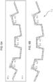
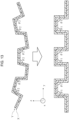
- the side walls are, for example, 101 and 401 in FIGS. 1 and 4 .
- the connecting wall is, for example, 102, 402, and 403 in FIGS. 1 and 4 . As shown in FIGS. 1 and 4 , the connecting wall connects the pair of side walls.
- the molded body has a shape with multiple waves and a length in a wave direction is 1 m or more.
- the wave direction here is the y-axis direction in FIG. 4
- the plate thickness direction is the z-axis direction in FIG. 4
- the molded body having a wave shape in cross section refers to a molded body in which a wave can be observed when a cross section of the molded body is observed. It is general to observe the cross section in an in-plane direction (a direction perpendicular to a plate thickness direction).
- a relationship between a flatness Fa of the molded body and a height h of the side wall of the present invention preferably satisfies 0 ⁇ Fa/h ⁇ 1.1.
- the flatness Fa of the present invention is defined by the following procedures 1 to 5.
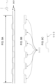
- Procedures 1 to 5 will be described with reference to FIGS. 9A to 9C .
- FIG. 9A shows a molded body left to stand such that the molding material X present in a surface layer is on a lower side.
- a surface layer of the molded body on the lower side of the paper surface is covered with the molding material X.
- the Y-axis direction in FIG. 9A is the wave direction.
- the observation range of the molded body is cut out such that the length Ly is 40 cm, and the cross section of the wave shape is observed (procedure 2).
- the lower wall of the connecting wall is a region indicated by 902 in FIG. 9B .
- the bottom surface of the lower wall is a surface indicated by 903 in FIG. 9C (procedure 3).
- the two parallel ideal straight lines are drawn such that the entire lower wall of the connecting wall is disposed between the two parallel ideal straight lines and a distance between the two parallel ideal straight lines (901) is minimized.
- a method of observing and measuring a state in which the top and bottom of the molded body in FIG. 9A are reversed and the surface of the molded body on the lower side of the paper surface is covered with the molding material Y (in a state in which the molding material Y is in contact with a desk top) is not employed in the present invention.
- Fa should be designed so as to satisfy 0 ⁇ Fa/h ⁇ 1.1 even at one location.
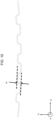
- the height h of the side wall of the present invention is shown by h in FIG. 10 , which indicates a distance between the upper wall and the lower wall when observing the cross section of the wave shape. More specifically, when an upper wall and a lower wall directly connected to one side wall are observed, a distance between the ideal straight lines is a height h when two parallel ideal straight lines are drawn with a minimum necessary width such that the entire upper wall and the lower wall are disposed between the two parallel ideal straight lines.
- the two parallel dotted lines shown in FIG. 10 are drawn such that the entire upper wall and the entire lower wall directly connected to one side wall are arranged between two parallel dotted lines, and a distance between the two parallel dotted lines is minimized.
- At least one h may satisfy 0 ⁇ Fa/h ⁇ 1.1.
- Fa/h 0
- the lower wall of the molded body is an ideal plane.
- Fa/h ⁇ 1.1 it is easy to assemble, for example, an automobile in combination with other components.
- 0 ⁇ Fa/h ⁇ 1.0 is preferable
- 0 ⁇ Fa/h ⁇ 0.7 is more preferable
- 0 ⁇ Fa/h ⁇ 0.4 is still more preferable
- 0 ⁇ Fa/h ⁇ 0.2 is yet still more preferable
- 0 ⁇ Fa/h ⁇ 0.15 is most preferable.
- an angle ⁇ 1 between the side wall and the connecting wall on the side where the material B is present in the surface layer preferably satisfies 90° ⁇ ⁇ 1 ⁇ 160°.
- the angle ⁇ 1 between the side wall and the connecting wall on the side where the material B is present in the surface layer is indicated by ⁇ 1 in FIGS. 1 and 4 , for example. That is, the angle ⁇ 1 can be measured when the cross section of the wave shape is observed.
- the molded bodies in FIGS. 1 and 4 have a plurality of ⁇ 1 at the same angle.
- the angles ⁇ 1 When there are a plurality of angles ⁇ 1, but the angles are different from each other, the smallest angle among the angles between the side wall and the connecting wall on the side where the material B is present in the surface layer is defined as the angle ⁇ 1.
- the range of the angle ⁇ 1 is more preferably 95° ⁇ ⁇ 1 ⁇ 135°, even more preferably 95° ⁇ ⁇ 1 ⁇ 125°, and still more preferably 98° ⁇ ⁇ 1 ⁇ 120°.
- the molding material X pulls the molding material Y, for example, immediately after the cold pressing is completed in FIGS.
- both end portions of the molded body (in the wave direction) warp in the downward direction of the paper plane with a lapse of time.
- the angle between the side wall and the connecting wall on the side where the material B is present in the surface layer changes (sometimes referred to as an angle change) between immediately after molding and after a lapse of a while.
- the problem of warpage of the entire molded body becomes significant as the length in the wave direction increases (specifically, when the length in the wave direction is 1 m or more) and as the number of angles ⁇ 1 increases.
- a molded body having a small Fa/h value can be manufactured even when the length in the wave direction is long or the like.
- the molded body in the present invention preferably has a rib between the connecting wall and the side wall.
- the rib is shown by 701 in FIGS. 7A and 7B , for example.
- the molded body may be joined to a separate component to manufacture a joined body in a state in which the angle ⁇ 1 is reduced by stress deformation and the relationship between the flatness Fa' of the molded body after stress deformation and the height h of the side wall satisfies 0 ⁇ Fa'/h ⁇ 0.1.
- a slightly warped molded body as shown in FIG. 8A may be joined to a separate component (802 in FIG. 8B ) after stress is applied to the molded body as indicated by an arrow 801 in FIG. 8A and the angle ⁇ 1 is changed to the angle ⁇ 3.
- the flatness Fa' means the flatness of the molded body in a joined state.
- the joining may be performed by bolting as shown in FIG. 8B , or may be performed by joining with an adhesive.
- a layer containing carbon fibers for example, layer Yc
- the thermal conductivity is high, and the fluidity is inferior because the layer is more easily cooled than a layer containing glass fibers under the same conditions (resin, additive, Vf, and the like).
- the material A contains carbon fibers, the appearance is beautiful, and when the material A is present on the surface, the appeal to the customer is high.
- the molding material Y has a grain, the design is exceptional. In order to form the grain on the molding material Y, it is necessary to pressurize the molding material Y immediately after the molding material Y comes into contact with the mold My. Therefore, it is preferable that the mold My to be in contact with the molding material Y is an upper mold.
- a molded body heated to a first predetermined temperature is put into a mold set to a second predetermined temperature, and then pressurized and cooled.
- the first predetermined temperature is equal to or higher than the melting point and the second predetermined temperature is less than the melting point.
- the thermoplastic resins are the same kind of resin and are amorphous, the first predetermined temperature is equal to or higher than the glass transition temperature, and the second predetermined temperature is lower than the glass transition temperature.
- the first predetermined temperature is determined based on the higher melting point or glass transition temperature of the resin
- the second predetermined temperature is determined based on the lower melting point or glass transition temperature of the resin.
- Step A2) placing the material heated in step A1) in a mold adjusted to the second predetermined temperature, and pressurizing the material
- the molding of the molded body can be completed.
- Step A2) is a step of applying pressure to the material to obtain a molded body having a desired shape.
- the molding pressure at this time is not particularly limited, but is preferably less than 20 MPa, and more preferably 10 MPa or less with respect to a projected area of the mold cavity.
- the mold Mx includes a mold surface S1 for forming the connecting wall and a mold surface S2 for forming the side wall, and an angle ⁇ 2 between S1 and S2 satisfies ⁇ 1 ⁇ ⁇ 2, and more preferably satisfies ⁇ 1 ⁇ ⁇ 2.
- an obtuse angle portion of the angle between S1 and S2 is measured.
- an obtuse angle portion of the lower mold (mold Mx) with which the molding material X comes into contact is measured.
- the mold cavity preferably has a wave shape in cross section, and the angle ⁇ 2 can be measured when the mold cavity is observed in the wave shape in cross section.
- the mold cavity in FIGS. 3A and 6A have a plurality of ⁇ 2 at the same angle.
- the angle ⁇ 2 is the smallest angle among the angles between the mold surface S1 and the mold surface S2.
- the range of ⁇ 2 is more preferably 0° ⁇ ⁇ 2 - ⁇ 1 ⁇ 10°, and still more preferably 0° ⁇ ⁇ 2 - ⁇ 1 ⁇ 5°.
- the flatness Fc of the present invention is defined by the following procedures 1' to 5'. (Procedure 1') The mold cavity is observed such that the mold to be in contact with the molding material X is the lower mold.
- the mold cavity is preferably observed such that the mold to be in contact with the layer Xg is the lower mold.
- Procedure 1' to procedure 5' will be described with reference to FIG. 12 .
- the mold cavity is observed such that the mold Mx to be in contact with the molding material X is the lower mold.
- the Y-axis direction in FIG. 12 is the wave direction.
- the cross section of the mold cavity having the wave shape is observed, and the observation range of the mold cavity is cut out such that the length Lyc in the wave direction is 40 cm.
- the mold surface for forming the lower wall is 1201 in FIG. 12 .
- the two parallel ideal straight lines are drawn such that the entire mold surface for forming the lower wall is disposed between the two parallel ideal straight lines and a distance between the two parallel ideal straight lines (1202) is minimized.
- Fc changes depending on the location where the length Lyc in the wave direction is cut out
- the flatness Fc of the mold cavity used for cold pressing satisfies Fa ⁇ Fc.
- Fa ⁇ Fc means that the molded body is closer to a flat surface than the mold cavity.
- the angle between the side wall and the connecting wall on the side where the molding material X is present in the surface layer changes between immediately after molding and after a lapse of a while, causing an angle change.
- Carbon fiber "Tenax” (registered trademark) STS40-24K (EP) (average fiber diameter: 7 ⁇ m, fineness: 1600 tex, density: 1.78 g/cm 3 ) manufactured by Teijin, Ltd.
- Glass fiber E-glass RS 240QR-483 (count: 2400 g/1000 m) manufactured by Nitto Boseki Co., Ltd.
- Polyamide 6 (A1030 manufactured by Unitika Ltd., sometimes abbreviated as PA6)
- Polyamide 6 (A1030 manufactured by Unitika Ltd., sometimes abbreviated as PA6)
- a sample of 100 mm ⁇ 100 mm is cut out from the manufactured molding material X (or molding material Y).
- the weights of the resin, the carbon fiber, and the glass fiber are calculated by weighing the weights of (i) to (iii). Next, the volume fraction of the reinforcing fibers was calculated using the specific gravity of each component.
- Fiber volume fraction Vfx 100 ⁇ volume of reinforcing fibers/(volume of reinforcing fibers + volume of thermoplastic resin Rx of molding material X)
- Fiber volume fraction Vfy 100 ⁇ volume of reinforcing fibers/(volume of reinforcing fibers + volume of thermoplastic resin Ry of molding material Y)
- the mold When placing the molding material in the mold, the mold is pre-marked and transferred to the molding material.
- a total of 13 points are marked, one point at the center and 12 points on the circumference so as to draw a circle.
- the circle has a diameter of 300 mm, and markings of 12 points on a circumference are drawn such that a distance therebetween is uniform.
- six imaginary lines are drawn in the diameter direction into the mold (for example, FIG. 16 ).
- Lti (i is 1 to 6) before transfer is measured by measuring a distance between two points in an i direction marked on a mold at a molding temperature
- Lei after transfer is measured by measuring a distance between two points in the i direction marked on a molded body cooled to room temperature
- an average molding shrinkage is calculated from the above formula (3).
- Cross sections of the molded body and the mold cavity were observed from a direction in which a wave shape could be observed. More specifically, observation was made from a direction (X-axis direction in FIGS. 1 and 4 ) that is perpendicular to the wave direction (Y-axis direction in FIGS. 1 and 4 ) and in which the wave shape could be observed. The direction for observation is also perpendicular to a plate thickness direction (Z-axis direction in FIGS. 1 and 4 ). In other words, observation of the wave shape was performed from a direction perpendicular to both the wave direction and the plate thickness direction.
- the flatness Fa was measured by the following procedure.
- Procedure 2 The cross section of the molded body was observed such that the cross section appeared to have a wave shape, and the observation range of the molded body was cut out such that the length Ly in the wave direction was 40 cm.
- the flatness Fc was measured by the following procedure.
- the cross section of the molded body having a wave shape was observed, all the angles between the side wall and the connecting wall on the side where the molding material X was present in the surface layer were measured, and the minimum angle was defined as an angle ⁇ 1.
- An angle ⁇ 2 between a mold surface S1 for forming the connecting wall and a mold surface S2 for forming the side wall when the mold Mx was observed in cross section was designed according to each of Examples and Comparative Examples.
- test conditions were as follows: a weight mass was 16 kg, and heights were adjusted such that an impact of 135J, 145J, 155J, and 165J was applied respectively, and the following evaluation was performed.
- Carbon fibers "Tenax” (registered trademark) STS40-24K (average fiber diameter: 7 ⁇ m, number of single fibers: 24.000) manufactured by Toho Tenax Co., Ltd. and cut to a fiber length of 20 mm were used as carbon fibers, and a Nylon 6 resin A1030 manufactured by Unitika Ltd. was used as a resin, and a composite composition of carbon fibers and Nylon 6 resin in which carbon fibers were two-dimensionally and randomly oriented was prepared based on a method described in US Patent No. 8946342 .
- the obtained composite composition was heated at 2.0 MPa for 5 minutes in a press device heated to 260°C to obtain flat plate-shaped layer Xc of 475 mm ⁇ 350 mm having an average thickness of 0.18 mm,.
- Table 1 shows the analysis results of the carbon fibers contained in the layer Xc.
- the obtained composite composition was heated at 2.0 MPa for 5 minutes in a press device heated to 260°C to obtain a flat plate-shaped layer Xg of 475 mm ⁇ 350 mm having an average thickness of 0.32 mm.
- Table 1 shows the analysis results of the glass fibers contained in the layer Xg.
- Laminated bodies Px were produced by lamination so as to be Xg/Xc/Xg/Xc/Xg as shown in Table 1.
- the layer Xg is simply referred to as Xg
- the layer Xc is simply referred to as Xc.
- the layer Xg is three layers, and the layer Xc is two layers.
- the obtained laminated body Px was used as the molding material X.
- FIG. 14 shows a laminated structure of the molding material X.
- a composite composition of the carbon fiber and the nylon 6 resin was prepared, in which carbon fibers were two-dimensionally and randomly oriented.
- the obtained composite composition was heated at 2.0 MPa for 5 minutes in a press device heated to 260°C to produce a flat plate-shaped material (layer Yc) of 475 mm ⁇ 350 mm having an average thickness of 0.8 mm.
- Table 1 shows the analysis results of the carbon fibers contained in the layer Yc.
- the laminated body Py was laminated so that the configuration is Yc/Ycg/Yc.
- the layer Yc is simply referred to as Yc
- the layer Ycg is simply referred to as Ycg.
- the obtained laminated body Py was used as the molding material Y.
- FIG. 14 shows a laminated structure of the molding material Y.
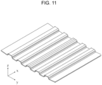
- a mold for producing a molded body shown in FIG. 11 was prepared.
- a length of the molded body in the Y-axis direction was 40 cm, which was defined as Ly.
- the flatness Fc was set to 0 mm
- the angle ⁇ 2 was set to 103° (the angles between S1 and S2 were all the same angle)
- the temperature ta of the mold My was set to 150°C
- the temperature tb of the mold Mx was set to 150°C.
- the molding material X and the molding material Y were dried in a hot air dryer at 120°C for 4 hours, and then the molding material Y and the molding material X were laminated in order, and the temperature was increased to 290°C by an infrared heater. Since the molding material X and the molding material Y are symmetric materials, there is no front or back surface.
- the upper mold was lowered, and the molding material Y and the molding material X were pressed at the same time for 1 minute at a pressing pressure of 20 MPa (a time of 1 second from the start of pressing until reaching 20 MPa) to produce a cold-pressed body (400 mm ⁇ 350 mm: wave direction (y-axis direction in FIG. 11 ) ⁇ direction orthogonal to the wave direction (x-axis direction in FIG. 11 )).
- the molded body After one hour from the completion of the cold-pressing, the molded body had a wave shape shown in FIG. 11 .
- the height h of the side wall was 12 mm
- the length of the upper wall was 23 mm
- the length of the lower wall was 25 mm.
- Both the upper wall and the lower wall were connecting wall, and the molded body was observed so that the molding material X is on the lower side, and the length was measured by defining the upper wall and the lower wall.
- a composite composition of the carbon fiber and the nylon 6 resin was prepared, in which carbon fibers were randomly oriented in two dimensions.
- the obtained composite composition was heated at 2.0 MPa for 5 minutes in a press device heated to 260°C to obtain a flat plate-shaped layer Yc of 475 mm ⁇ 350 mm having an average thickness of 3.7 mm.
- only the layer Yc was used as the molding material Y.
- the reinforcing fibers in the molding material X in Examples and Comparative Examples are dispersed two-dimensionally randomly.
- the reinforcing fibers of the Xc layer, the Xg layer, and the Yc layer are dispersed two-dimensionally randomly.
- the molded body of the present invention and the molded body obtained by molding the molded body are used in various constituent members, for example, structural members of automobiles, various electric products, frames and housings of machines, and all other parts where impact absorbing is desired. Particularly preferably, it can be used as an automobile part.
Landscapes
- Engineering & Computer Science (AREA)
- Mechanical Engineering (AREA)
- Chemical & Material Sciences (AREA)
- Composite Materials (AREA)
- Textile Engineering (AREA)
- Inorganic Chemistry (AREA)
- Laminated Bodies (AREA)
- Moulding By Coating Moulds (AREA)
- Casting Or Compression Moulding Of Plastics Or The Like (AREA)
Claims (16)
- Verfahren zur Herstellung eines Formkörpers durch Laminieren und Kaltpressen einer Formmasse X und einer Formmasse Y, wobei:die Formmasse X diskontinuierliche Kohlenstofffasern Cx, diskontinuierliche Glasfasern Gx und ein Matrixharz Rx enthält, wobei die Kohlenstofffasern Cx Kohlenstofffasern Cx1 mit einer Faserbreite von weniger als 0,3 mm und Kohlenstofffasern Cx2 mit einer Faserbreite von 0,3 mm oder mehr und 3,0 mm oder weniger enthalten;ein Volumenverhältnis der Kohlenstofffasern Cx2 zu den Kohlenstofffasern Cx 10 Vol.-% oder mehr und weniger als 99 Vol.-% beträgt;ein Volumenverhältnis der Kohlenstofffasern Cx zu den Glasfasern Gx 0,1 oder mehr und 1,5 oder weniger beträgt;eine mittlere Formschrumpfung X in einer in der Ebene liegenden Richtung der Formmasse X folgende Formel (1) erfüllt;die Formmasse Y diskontinuierliche Kohlenstofffasern Cy und/oder Glasfasern Gy und ein Matrixharz Ry enthält; undeine mittlere Formschrumpfung Y der Formmasse Y in einer in der Ebene liegenden Richtung folgende Formel (2) erfüllt:

0,1 < mittlere Formschrumpfung Y / mittlere Formschrumpfung X < 1,5. - Verfahren zur Herstellung eines Formkörpers nach Anspruch 1,
wobei eine gewichtsgemittelte Faserlänge der Kohlenstofffasern Cx gleich 1 mm oder mehr und 100 mm oder weniger und eine gewichtsgemittelte Faserlänge der Glasfasern Gx gleich 1 mm oder mehr und 100 mm oder weniger beträgt. - Verfahren zur Herstellung eines Formkörpers nach Anspruch 1 oder 2, wobei die Formmasse X eine Formmasse ist, in der die Kohlenstofffasern Cx und die Glasfasern Gx in derselben Schicht vermischt sind.
- Verfahren zur Herstellung eines Formkörpers nach einem der Ansprüche 1 bis 3, wobei zumindest eine äußerste Schicht, wenn der Formkörper gebildet ist, die Glasfasern Gx enthält.
- Verfahren zur Herstellung eines Formkörpers nach einem der Ansprüche 1 bis 4, wobei es sich bei der Formmasse X um einen laminierten Körper Px handelt, in dem eine Schicht Xc und eine Schicht Xg laminiert sind, wobei die Schicht Xc die Kohlenstofffasern Cx und die Schicht Xg die Glasfasern Gx enthält.
- Verfahren zur Herstellung eines Formkörpers nach Anspruch 5, wobei zumindest eine äußerste Schicht, wenn der Formkörper gebildet ist, die Schicht Xg ist.
- Verfahren zur Herstellung eines Formkörpers nach einem der Ansprüche 1 bis 6, wobei es sich bei der Formmasse Y um einen laminierten Körper Py handelt, in dem eine Schicht Yc und eine Schicht Ycg laminiert sind, wobei die Schicht Yc diskontinuierliche Kohlenstofffasern Cyc und die Schicht Ycg Kohlenstofffasern Cycg und/oder die Glasfasern Gy enthält.
- Verfahren zur Herstellung eines Formkörpers nach Anspruch 7, wobei zumindest eine äußerste Schicht, wenn der Formkörper gebildet ist, die Schicht Yc ist.
- Verfahren zur Herstellung eines Formkörpers nach Anspruch 8, wobei der laminierte Körper Py einen dreischichtigen Aufbau aus der Schicht Yc, der Schicht Ycg und der Schicht Yc hat.
- Verfahren zur Herstellung eines Formkörpers nach Anspruch 9, wobei eine gewichtsgemittelte Faserlänge der Kohlenstofffasern Cyc, die in der Schicht Yc enthalten sind, länger ist als eine gewichtsgemittelte Faserlänge der Kohlenstofffasern Cycg und/oder der Glasfasern Gy, die in der Schicht Ycg enthalten sind.
- Verfahren zur Herstellung eines Formkörpers nach einem der Ansprüche 1 bis 10, wobei es sich bei den Kohlenstofffasern Cx und/oder den Glasfasern Gx und/oder den Kohlenstofffasern Cy und/oder den Glasfasern Gy um recycelte Fasern handelt.
- Verfahren zur Herstellung eines Formkörpers nach einem der Ansprüche 1 bis 11, wobei es sich bei dem in der Formmasse X enthaltenen Matrixharz Rx und bei dem in der Formmasse Y enthaltenen Matrixharz Ry um thermoplastische Harze handelt.
- Verfahren zur Herstellung eines Formkörpers nach einem der Ansprüche 1 bis 12, wobei der Formkörper ein schlagfestes Element ist und die Formmasse Y eine Seite darstellt, die einem Schlag ausgesetzt ist.
- Verfahren zur Herstellung eines Formkörper nach Anspruch 13, wobei es sich bei der Formmasse Y um einen laminierten Körper Py handelt, in dem eine Schicht Yc und eine Schicht Ycg laminiert sind, der Formkörper ein schlagfestes Element ist und die Schicht Yc eine Seite darstellt, die einem Schlag ausgesetzt ist.
- Verfahren zur Herstellung eines Formkörpers nach einem der Ansprüche 1 bis 14, wobei die Formmasse X und die Formmasse Y eine flache Plattenform haben.
- Verfahren zur Herstellung eines Formkörpers nach einem der Ansprüche 1 bis 15, wobei eine Dicke lx der Formmasse X gleich 0,5 mm oder mehr und 5,0 mm oder weniger beträgt, und eine Dicke ly der Formmasse Y gleich 0,5 mm oder mehr und weniger als 5,0 mm beträgt.
Applications Claiming Priority (2)
| Application Number | Priority Date | Filing Date | Title |
|---|---|---|---|
| JP2021163769 | 2021-10-04 | ||
| PCT/JP2022/036282 WO2023058535A1 (ja) | 2021-10-04 | 2022-09-28 | 炭素繊維とガラス繊維を含んだ成形材料及び、これをコールドプレスして成形体を製造する方法 |
Publications (4)
| Publication Number | Publication Date |
|---|---|
| EP4414152A1 EP4414152A1 (de) | 2024-08-14 |
| EP4414152A4 EP4414152A4 (de) | 2025-01-08 |
| EP4414152B1 true EP4414152B1 (de) | 2025-07-02 |
| EP4414152B9 EP4414152B9 (de) | 2025-09-10 |
Family
ID=85803419
Family Applications (1)
| Application Number | Title | Priority Date | Filing Date |
|---|---|---|---|
| EP22878405.4A Active EP4414152B9 (de) | 2021-10-04 | 2022-09-28 | Formmaterial mit kohlenstofffasern und glasfasern und verfahren zur herstellung eines formkörpers durch kaltpressen davon |
Country Status (5)
| Country | Link |
|---|---|
| US (1) | US20250303616A1 (de) |
| EP (1) | EP4414152B9 (de) |
| JP (1) | JP7393588B2 (de) |
| CN (1) | CN117980125A (de) |
| WO (1) | WO2023058535A1 (de) |
Family Cites Families (13)
| Publication number | Priority date | Publication date | Assignee | Title |
|---|---|---|---|---|
| JPH059301A (ja) * | 1990-12-17 | 1993-01-19 | Nippon Steel Corp | スタンピング成形材料およびスタンピング成形品 |
| JPH09277420A (ja) * | 1996-04-19 | 1997-10-28 | Toray Ind Inc | 繊維強化プラスチック構造体およびその製造方法 |
| JP5436700B2 (ja) | 2011-02-01 | 2014-03-05 | 帝人株式会社 | ランダムマット、および繊維強化複合材料 |
| JP5979426B2 (ja) | 2012-07-12 | 2016-08-24 | 三菱レイヨン株式会社 | シートモールディングコンパウンド |
| US9592853B2 (en) | 2014-07-02 | 2017-03-14 | GM Global Technology Operations LLC | Corrugation designs |
| US9650003B2 (en) | 2014-07-02 | 2017-05-16 | GM Global Technology Operations LLC | Impact resistant component for a vehicle |
| EP3395529B1 (de) * | 2015-12-25 | 2021-02-24 | Teijin Limited | Pressformmaterial mit diskontinuierlicher verstärkungsfaser und thermoplastischem harz als matrix |
| CN109715385B (zh) | 2016-09-14 | 2021-04-27 | 三菱化学株式会社 | 层叠基材及其制造方法 |
| JP6801321B2 (ja) | 2016-09-14 | 2020-12-16 | 三菱ケミカル株式会社 | リブ成形用積層基材 |
| CN112041143A (zh) * | 2018-06-07 | 2020-12-04 | 东丽株式会社 | 一体化成型体及其制造方法 |
| US20220227079A1 (en) * | 2020-01-27 | 2022-07-21 | Teijin Limited | Cold Press Molded Body Containing Carbon Fiber and Glass Fiber, and Manufacturing Method Thereof |
| JP2021163769A (ja) | 2020-03-30 | 2021-10-11 | 日本電産株式会社 | 電子部品搭載基板の製造方法 |
| JP7377993B2 (ja) * | 2020-11-04 | 2023-11-10 | 帝人株式会社 | 圧縮成形して成形体を製造する方法 |
-
2022
- 2022-09-28 EP EP22878405.4A patent/EP4414152B9/de active Active
- 2022-09-28 CN CN202280064757.XA patent/CN117980125A/zh active Pending
- 2022-09-28 WO PCT/JP2022/036282 patent/WO2023058535A1/ja not_active Ceased
- 2022-09-28 JP JP2023514989A patent/JP7393588B2/ja active Active
- 2022-09-28 US US18/287,101 patent/US20250303616A1/en active Pending
Also Published As
| Publication number | Publication date |
|---|---|
| WO2023058535A1 (ja) | 2023-04-13 |
| US20250303616A1 (en) | 2025-10-02 |
| JP7393588B2 (ja) | 2023-12-06 |
| EP4414152A4 (de) | 2025-01-08 |
| JPWO2023058535A1 (de) | 2023-04-13 |
| EP4414152B9 (de) | 2025-09-10 |
| EP4414152A1 (de) | 2024-08-14 |
| CN117980125A (zh) | 2024-05-03 |
Similar Documents
| Publication | Publication Date | Title |
|---|---|---|
| EP3513963B1 (de) | Schichtsubstrat und verfahren zur herstellung davon | |
| EP3112110B1 (de) | Kohlenstofffaserverstärktes formmaterial und formkörper | |
| JP5551386B2 (ja) | 繊維・樹脂複合化シート及びfrp成形体 | |
| EP3395529B1 (de) | Pressformmaterial mit diskontinuierlicher verstärkungsfaser und thermoplastischem harz als matrix | |
| CN104136675B (zh) | 无序毡和纤维增强复合材料成形制品 | |
| CN105073848A (zh) | 碳纤维增强热塑性树脂复合材料和使用其的成型体 | |
| EP3029089B1 (de) | Faserverstärkter verbundstoff und verfahren zur herstellung davon | |
| EP2752285A1 (de) | Herstellungsverfahren für einen verbundformkörper mit unterschnittenem querschnitt | |
| CN107530926A (zh) | 纤维增强复合材料成型品及其制造方法 | |
| EP3950281B1 (de) | Verfahren zur herstellung eines pressgeformten körpers | |
| EP4212327A1 (de) | Verfahren zur durchführung von pressformen und herstellung eines formartikels | |
| JP7267466B2 (ja) | 炭素繊維とガラス繊維を含むコールドプレス成形体、およびその製造方法 | |
| EP4414152B9 (de) | Formmaterial mit kohlenstofffasern und glasfasern und verfahren zur herstellung eines formkörpers durch kaltpressen davon | |
| JP7025273B2 (ja) | 成形体の製造方法 | |
| EP3885097B1 (de) | Verfahren zur herstellung eines pressformkörpers | |
| JP7767551B1 (ja) | 繊維強化プラスチック成形体の製造方法、および繊維強化プラスチック成形体 | |
| CN116834336A (zh) | 一种电池包壳体的制备方法 |
Legal Events
| Date | Code | Title | Description |
|---|---|---|---|
| STAA | Information on the status of an ep patent application or granted ep patent |
Free format text: STATUS: THE INTERNATIONAL PUBLICATION HAS BEEN MADE |
|
| PUAI | Public reference made under article 153(3) epc to a published international application that has entered the european phase |
Free format text: ORIGINAL CODE: 0009012 |
|
| STAA | Information on the status of an ep patent application or granted ep patent |
Free format text: STATUS: REQUEST FOR EXAMINATION WAS MADE |
|
| 17P | Request for examination filed |
Effective date: 20231221 |
|
| AK | Designated contracting states |
Kind code of ref document: A1 Designated state(s): AL AT BE BG CH CY CZ DE DK EE ES FI FR GB GR HR HU IE IS IT LI LT LU LV MC MK MT NL NO PL PT RO RS SE SI SK SM TR |
|
| A4 | Supplementary search report drawn up and despatched |
Effective date: 20241205 |
|
| DAV | Request for validation of the european patent (deleted) | ||
| DAX | Request for extension of the european patent (deleted) | ||
| RIC1 | Information provided on ipc code assigned before grant |
Ipc: B29C 70/12 20060101ALI20241202BHEP Ipc: B29C 70/46 20060101ALI20241202BHEP Ipc: B29C 43/20 20060101ALI20241202BHEP Ipc: B29B 11/16 20060101ALI20241202BHEP Ipc: B29C 70/34 20060101ALI20241202BHEP Ipc: B32B 5/26 20060101ALI20241202BHEP Ipc: B29C 70/08 20060101ALI20241202BHEP Ipc: B29K 105/12 20060101ALI20241202BHEP Ipc: B29K 101/12 20060101ALI20241202BHEP Ipc: B29C 70/42 20060101ALI20241202BHEP Ipc: B29C 70/10 20060101ALI20241202BHEP Ipc: B29C 43/34 20060101ALI20241202BHEP Ipc: B29C 43/54 20060101AFI20241202BHEP |
|
| GRAP | Despatch of communication of intention to grant a patent |
Free format text: ORIGINAL CODE: EPIDOSNIGR1 |
|
| STAA | Information on the status of an ep patent application or granted ep patent |
Free format text: STATUS: GRANT OF PATENT IS INTENDED |
|
| INTG | Intention to grant announced |
Effective date: 20250207 |
|
| GRAS | Grant fee paid |
Free format text: ORIGINAL CODE: EPIDOSNIGR3 |
|
| GRAA | (expected) grant |
Free format text: ORIGINAL CODE: 0009210 |
|
| STAA | Information on the status of an ep patent application or granted ep patent |
Free format text: STATUS: THE PATENT HAS BEEN GRANTED |
|
| AK | Designated contracting states |
Kind code of ref document: B1 Designated state(s): AL AT BE BG CH CY CZ DE DK EE ES FI FR GB GR HR HU IE IS IT LI LT LU LV MC MK MT NL NO PL PT RO RS SE SI SK SM TR |
|
| P01 | Opt-out of the competence of the unified patent court (upc) registered |
Free format text: CASE NUMBER: APP_24494/2025 Effective date: 20250522 |
|
| REG | Reference to a national code |
Ref country code: GB Ref legal event code: FG4D |
|
| REG | Reference to a national code |
Ref country code: CH Ref legal event code: EP |
|
| REG | Reference to a national code |
Ref country code: DE Ref legal event code: R096 Ref document number: 602022017112 Country of ref document: DE |
|
| REG | Reference to a national code |
Ref country code: IE Ref legal event code: FG4D |
|
| REG | Reference to a national code |
Ref country code: CH Ref legal event code: PK Free format text: BERICHTIGUNG B9 |
|
| PGFP | Annual fee paid to national office [announced via postgrant information from national office to epo] |
Ref country code: DE Payment date: 20250805 Year of fee payment: 4 |
|
| PGFP | Annual fee paid to national office [announced via postgrant information from national office to epo] |
Ref country code: FR Payment date: 20250808 Year of fee payment: 4 Ref country code: AT Payment date: 20251020 Year of fee payment: 4 |
|
| REG | Reference to a national code |
Ref country code: NL Ref legal event code: MP Effective date: 20250702 |
|
| PG25 | Lapsed in a contracting state [announced via postgrant information from national office to epo] |
Ref country code: PT Free format text: LAPSE BECAUSE OF FAILURE TO SUBMIT A TRANSLATION OF THE DESCRIPTION OR TO PAY THE FEE WITHIN THE PRESCRIBED TIME-LIMIT Effective date: 20251103 |
|
| PG25 | Lapsed in a contracting state [announced via postgrant information from national office to epo] |
Ref country code: NL Free format text: LAPSE BECAUSE OF FAILURE TO SUBMIT A TRANSLATION OF THE DESCRIPTION OR TO PAY THE FEE WITHIN THE PRESCRIBED TIME-LIMIT Effective date: 20250702 |
|
| REG | Reference to a national code |
Ref country code: AT Ref legal event code: MK05 Ref document number: 1808757 Country of ref document: AT Kind code of ref document: T Effective date: 20250702 |
|
| PG25 | Lapsed in a contracting state [announced via postgrant information from national office to epo] |
Ref country code: IS Free format text: LAPSE BECAUSE OF FAILURE TO SUBMIT A TRANSLATION OF THE DESCRIPTION OR TO PAY THE FEE WITHIN THE PRESCRIBED TIME-LIMIT Effective date: 20251102 |
|
| PG25 | Lapsed in a contracting state [announced via postgrant information from national office to epo] |
Ref country code: NO Free format text: LAPSE BECAUSE OF FAILURE TO SUBMIT A TRANSLATION OF THE DESCRIPTION OR TO PAY THE FEE WITHIN THE PRESCRIBED TIME-LIMIT Effective date: 20251002 |
|
| REG | Reference to a national code |
Ref country code: LT Ref legal event code: MG9D |
|
| PG25 | Lapsed in a contracting state [announced via postgrant information from national office to epo] |
Ref country code: AT Free format text: LAPSE BECAUSE OF FAILURE TO SUBMIT A TRANSLATION OF THE DESCRIPTION OR TO PAY THE FEE WITHIN THE PRESCRIBED TIME-LIMIT Effective date: 20250702 |
|
| PG25 | Lapsed in a contracting state [announced via postgrant information from national office to epo] |
Ref country code: FI Free format text: LAPSE BECAUSE OF FAILURE TO SUBMIT A TRANSLATION OF THE DESCRIPTION OR TO PAY THE FEE WITHIN THE PRESCRIBED TIME-LIMIT Effective date: 20250702 |
|
| PG25 | Lapsed in a contracting state [announced via postgrant information from national office to epo] |
Ref country code: HR Free format text: LAPSE BECAUSE OF FAILURE TO SUBMIT A TRANSLATION OF THE DESCRIPTION OR TO PAY THE FEE WITHIN THE PRESCRIBED TIME-LIMIT Effective date: 20250702 |
|
| PG25 | Lapsed in a contracting state [announced via postgrant information from national office to epo] |
Ref country code: GR Free format text: LAPSE BECAUSE OF FAILURE TO SUBMIT A TRANSLATION OF THE DESCRIPTION OR TO PAY THE FEE WITHIN THE PRESCRIBED TIME-LIMIT Effective date: 20251003 |
|
| PG25 | Lapsed in a contracting state [announced via postgrant information from national office to epo] |
Ref country code: SE Free format text: LAPSE BECAUSE OF FAILURE TO SUBMIT A TRANSLATION OF THE DESCRIPTION OR TO PAY THE FEE WITHIN THE PRESCRIBED TIME-LIMIT Effective date: 20250702 Ref country code: CZ Free format text: LAPSE BECAUSE OF FAILURE TO SUBMIT A TRANSLATION OF THE DESCRIPTION OR TO PAY THE FEE WITHIN THE PRESCRIBED TIME-LIMIT Effective date: 20250702 |
|
| PG25 | Lapsed in a contracting state [announced via postgrant information from national office to epo] |
Ref country code: LV Free format text: LAPSE BECAUSE OF FAILURE TO SUBMIT A TRANSLATION OF THE DESCRIPTION OR TO PAY THE FEE WITHIN THE PRESCRIBED TIME-LIMIT Effective date: 20250702 |
|
| PG25 | Lapsed in a contracting state [announced via postgrant information from national office to epo] |
Ref country code: BG Free format text: LAPSE BECAUSE OF FAILURE TO SUBMIT A TRANSLATION OF THE DESCRIPTION OR TO PAY THE FEE WITHIN THE PRESCRIBED TIME-LIMIT Effective date: 20250702 Ref country code: PL Free format text: LAPSE BECAUSE OF FAILURE TO SUBMIT A TRANSLATION OF THE DESCRIPTION OR TO PAY THE FEE WITHIN THE PRESCRIBED TIME-LIMIT Effective date: 20250702 |
|
| PG25 | Lapsed in a contracting state [announced via postgrant information from national office to epo] |
Ref country code: RS Free format text: LAPSE BECAUSE OF FAILURE TO SUBMIT A TRANSLATION OF THE DESCRIPTION OR TO PAY THE FEE WITHIN THE PRESCRIBED TIME-LIMIT Effective date: 20251002 |
|
| PG25 | Lapsed in a contracting state [announced via postgrant information from national office to epo] |
Ref country code: ES Free format text: LAPSE BECAUSE OF FAILURE TO SUBMIT A TRANSLATION OF THE DESCRIPTION OR TO PAY THE FEE WITHIN THE PRESCRIBED TIME-LIMIT Effective date: 20250702 |
|
| PG25 | Lapsed in a contracting state [announced via postgrant information from national office to epo] |
Ref country code: RO Free format text: LAPSE BECAUSE OF FAILURE TO SUBMIT A TRANSLATION OF THE DESCRIPTION OR TO PAY THE FEE WITHIN THE PRESCRIBED TIME-LIMIT Effective date: 20250702 |
|
| PG25 | Lapsed in a contracting state [announced via postgrant information from national office to epo] |
Ref country code: SM Free format text: LAPSE BECAUSE OF FAILURE TO SUBMIT A TRANSLATION OF THE DESCRIPTION OR TO PAY THE FEE WITHIN THE PRESCRIBED TIME-LIMIT Effective date: 20250702 |
|
| PG25 | Lapsed in a contracting state [announced via postgrant information from national office to epo] |
Ref country code: DK Free format text: LAPSE BECAUSE OF FAILURE TO SUBMIT A TRANSLATION OF THE DESCRIPTION OR TO PAY THE FEE WITHIN THE PRESCRIBED TIME-LIMIT Effective date: 20250702 |
|
| PG25 | Lapsed in a contracting state [announced via postgrant information from national office to epo] |
Ref country code: IT Free format text: LAPSE BECAUSE OF FAILURE TO SUBMIT A TRANSLATION OF THE DESCRIPTION OR TO PAY THE FEE WITHIN THE PRESCRIBED TIME-LIMIT Effective date: 20250702 |
|
| PG25 | Lapsed in a contracting state [announced via postgrant information from national office to epo] |
Ref country code: SK Free format text: LAPSE BECAUSE OF FAILURE TO SUBMIT A TRANSLATION OF THE DESCRIPTION OR TO PAY THE FEE WITHIN THE PRESCRIBED TIME-LIMIT Effective date: 20250702 |
|
| REG | Reference to a national code |
Ref country code: CH Ref legal event code: H13 Free format text: ST27 STATUS EVENT CODE: U-0-0-H10-H13 (AS PROVIDED BY THE NATIONAL OFFICE) Effective date: 20260504 |
|
| PLBE | No opposition filed within time limit |
Free format text: ORIGINAL CODE: 0009261 |
|
| STAA | Information on the status of an ep patent application or granted ep patent |
Free format text: STATUS: NO OPPOSITION FILED WITHIN TIME LIMIT |