EP4411487A2 - Bilderzeugungssystem - Google Patents
Bilderzeugungssystem Download PDFInfo
- Publication number
- EP4411487A2 EP4411487A2 EP24177282.1A EP24177282A EP4411487A2 EP 4411487 A2 EP4411487 A2 EP 4411487A2 EP 24177282 A EP24177282 A EP 24177282A EP 4411487 A2 EP4411487 A2 EP 4411487A2
- Authority
- EP
- European Patent Office
- Prior art keywords
- attached
- shutter
- image forming
- container
- developer
- Prior art date
- Legal status (The legal status is an assumption and is not a legal conclusion. Google has not performed a legal analysis and makes no representation as to the accuracy of the status listed.)
- Pending
Links
Images













Classifications
-
- G—PHYSICS
- G03—PHOTOGRAPHY; CINEMATOGRAPHY; ANALOGOUS TECHNIQUES USING WAVES OTHER THAN OPTICAL WAVES; ELECTROGRAPHY; HOLOGRAPHY
- G03G—ELECTROGRAPHY; ELECTROPHOTOGRAPHY; MAGNETOGRAPHY
- G03G15/00—Apparatus for electrographic processes using a charge pattern
- G03G15/06—Apparatus for electrographic processes using a charge pattern for developing
- G03G15/08—Apparatus for electrographic processes using a charge pattern for developing using a solid developer, e.g. powder developer
- G03G15/0822—Arrangements for preparing, mixing, supplying or dispensing developer
- G03G15/0877—Arrangements for metering and dispensing developer from a developer cartridge into the development unit
-
- G—PHYSICS
- G03—PHOTOGRAPHY; CINEMATOGRAPHY; ANALOGOUS TECHNIQUES USING WAVES OTHER THAN OPTICAL WAVES; ELECTROGRAPHY; HOLOGRAPHY
- G03G—ELECTROGRAPHY; ELECTROPHOTOGRAPHY; MAGNETOGRAPHY
- G03G15/00—Apparatus for electrographic processes using a charge pattern
- G03G15/06—Apparatus for electrographic processes using a charge pattern for developing
- G03G15/08—Apparatus for electrographic processes using a charge pattern for developing using a solid developer, e.g. powder developer
- G03G15/0822—Arrangements for preparing, mixing, supplying or dispensing developer
- G03G15/0865—Arrangements for supplying new developer
-
- G—PHYSICS
- G03—PHOTOGRAPHY; CINEMATOGRAPHY; ANALOGOUS TECHNIQUES USING WAVES OTHER THAN OPTICAL WAVES; ELECTROGRAPHY; HOLOGRAPHY
- G03G—ELECTROGRAPHY; ELECTROPHOTOGRAPHY; MAGNETOGRAPHY
- G03G15/00—Apparatus for electrographic processes using a charge pattern
- G03G15/06—Apparatus for electrographic processes using a charge pattern for developing
- G03G15/08—Apparatus for electrographic processes using a charge pattern for developing using a solid developer, e.g. powder developer
- G03G15/0822—Arrangements for preparing, mixing, supplying or dispensing developer
- G03G15/0865—Arrangements for supplying new developer
- G03G15/0867—Arrangements for supplying new developer cylindrical developer cartridges, e.g. toner bottles for the developer replenishing opening
-
- G—PHYSICS
- G03—PHOTOGRAPHY; CINEMATOGRAPHY; ANALOGOUS TECHNIQUES USING WAVES OTHER THAN OPTICAL WAVES; ELECTROGRAPHY; HOLOGRAPHY
- G03G—ELECTROGRAPHY; ELECTROPHOTOGRAPHY; MAGNETOGRAPHY
- G03G15/00—Apparatus for electrographic processes using a charge pattern
- G03G15/06—Apparatus for electrographic processes using a charge pattern for developing
- G03G15/08—Apparatus for electrographic processes using a charge pattern for developing using a solid developer, e.g. powder developer
- G03G15/0822—Arrangements for preparing, mixing, supplying or dispensing developer
- G03G15/0865—Arrangements for supplying new developer
- G03G15/0874—Arrangements for supplying new developer non-rigid containers, e.g. foldable cartridges, bags
-
- G—PHYSICS
- G03—PHOTOGRAPHY; CINEMATOGRAPHY; ANALOGOUS TECHNIQUES USING WAVES OTHER THAN OPTICAL WAVES; ELECTROGRAPHY; HOLOGRAPHY
- G03G—ELECTROGRAPHY; ELECTROPHOTOGRAPHY; MAGNETOGRAPHY
- G03G15/00—Apparatus for electrographic processes using a charge pattern
- G03G15/06—Apparatus for electrographic processes using a charge pattern for developing
- G03G15/08—Apparatus for electrographic processes using a charge pattern for developing using a solid developer, e.g. powder developer
- G03G15/0822—Arrangements for preparing, mixing, supplying or dispensing developer
- G03G15/0877—Arrangements for metering and dispensing developer from a developer cartridge into the development unit
- G03G15/0881—Sealing of developer cartridges
- G03G15/0886—Sealing of developer cartridges by mechanical means, e.g. shutter, plug
-
- G—PHYSICS
- G03—PHOTOGRAPHY; CINEMATOGRAPHY; ANALOGOUS TECHNIQUES USING WAVES OTHER THAN OPTICAL WAVES; ELECTROGRAPHY; HOLOGRAPHY
- G03G—ELECTROGRAPHY; ELECTROPHOTOGRAPHY; MAGNETOGRAPHY
- G03G15/00—Apparatus for electrographic processes using a charge pattern
- G03G15/06—Apparatus for electrographic processes using a charge pattern for developing
- G03G15/08—Apparatus for electrographic processes using a charge pattern for developing using a solid developer, e.g. powder developer
- G03G15/0894—Reconditioning of the developer unit, i.e. reusing or recycling parts of the unit, e.g. resealing of the unit before refilling with toner
-
- G—PHYSICS
- G03—PHOTOGRAPHY; CINEMATOGRAPHY; ANALOGOUS TECHNIQUES USING WAVES OTHER THAN OPTICAL WAVES; ELECTROGRAPHY; HOLOGRAPHY
- G03G—ELECTROGRAPHY; ELECTROPHOTOGRAPHY; MAGNETOGRAPHY
- G03G15/00—Apparatus for electrographic processes using a charge pattern
- G03G15/80—Details relating to power supplies, circuits boards, electrical connections
-
- G—PHYSICS
- G03—PHOTOGRAPHY; CINEMATOGRAPHY; ANALOGOUS TECHNIQUES USING WAVES OTHER THAN OPTICAL WAVES; ELECTROGRAPHY; HOLOGRAPHY
- G03G—ELECTROGRAPHY; ELECTROPHOTOGRAPHY; MAGNETOGRAPHY
- G03G21/00—Arrangements not provided for by groups G03G13/00 - G03G19/00, e.g. cleaning, elimination of residual charge
- G03G21/16—Mechanical means for facilitating the maintenance of the apparatus, e.g. modular arrangements
- G03G21/1604—Arrangement or disposition of the entire apparatus
- G03G21/1619—Frame structures
-
- G—PHYSICS
- G03—PHOTOGRAPHY; CINEMATOGRAPHY; ANALOGOUS TECHNIQUES USING WAVES OTHER THAN OPTICAL WAVES; ELECTROGRAPHY; HOLOGRAPHY
- G03G—ELECTROGRAPHY; ELECTROPHOTOGRAPHY; MAGNETOGRAPHY
- G03G21/00—Arrangements not provided for by groups G03G13/00 - G03G19/00, e.g. cleaning, elimination of residual charge
- G03G21/16—Mechanical means for facilitating the maintenance of the apparatus, e.g. modular arrangements
- G03G21/1642—Mechanical means for facilitating the maintenance of the apparatus, e.g. modular arrangements for connecting the different parts of the apparatus
- G03G21/1652—Electrical connection means
-
- G—PHYSICS
- G03—PHOTOGRAPHY; CINEMATOGRAPHY; ANALOGOUS TECHNIQUES USING WAVES OTHER THAN OPTICAL WAVES; ELECTROGRAPHY; HOLOGRAPHY
- G03G—ELECTROGRAPHY; ELECTROPHOTOGRAPHY; MAGNETOGRAPHY
- G03G21/00—Arrangements not provided for by groups G03G13/00 - G03G19/00, e.g. cleaning, elimination of residual charge
- G03G21/16—Mechanical means for facilitating the maintenance of the apparatus, e.g. modular arrangements
- G03G21/1661—Mechanical means for facilitating the maintenance of the apparatus, e.g. modular arrangements means for handling parts of the apparatus in the apparatus
- G03G21/1676—Mechanical means for facilitating the maintenance of the apparatus, e.g. modular arrangements means for handling parts of the apparatus in the apparatus for the developer unit
-
- G—PHYSICS
- G03—PHOTOGRAPHY; CINEMATOGRAPHY; ANALOGOUS TECHNIQUES USING WAVES OTHER THAN OPTICAL WAVES; ELECTROGRAPHY; HOLOGRAPHY
- G03G—ELECTROGRAPHY; ELECTROPHOTOGRAPHY; MAGNETOGRAPHY
- G03G2215/00—Apparatus for electrophotographic processes
- G03G2215/06—Developing structures, details
- G03G2215/066—Toner cartridge or other attachable and detachable container for supplying developer material to replace the used material
- G03G2215/0663—Toner cartridge or other attachable and detachable container for supplying developer material to replace the used material having a longitudinal rotational axis, around which at least one part is rotated when mounting or using the cartridge
-
- G—PHYSICS
- G03—PHOTOGRAPHY; CINEMATOGRAPHY; ANALOGOUS TECHNIQUES USING WAVES OTHER THAN OPTICAL WAVES; ELECTROGRAPHY; HOLOGRAPHY
- G03G—ELECTROGRAPHY; ELECTROPHOTOGRAPHY; MAGNETOGRAPHY
- G03G2215/00—Apparatus for electrophotographic processes
- G03G2215/06—Developing structures, details
- G03G2215/066—Toner cartridge or other attachable and detachable container for supplying developer material to replace the used material
- G03G2215/0663—Toner cartridge or other attachable and detachable container for supplying developer material to replace the used material having a longitudinal rotational axis, around which at least one part is rotated when mounting or using the cartridge
- G03G2215/0673—Generally vertically mounting of said toner cartridge parallel to its longitudinal rotational axis
-
- G—PHYSICS
- G03—PHOTOGRAPHY; CINEMATOGRAPHY; ANALOGOUS TECHNIQUES USING WAVES OTHER THAN OPTICAL WAVES; ELECTROGRAPHY; HOLOGRAPHY
- G03G—ELECTROGRAPHY; ELECTROPHOTOGRAPHY; MAGNETOGRAPHY
- G03G2215/00—Apparatus for electrophotographic processes
- G03G2215/06—Developing structures, details
- G03G2215/066—Toner cartridge or other attachable and detachable container for supplying developer material to replace the used material
- G03G2215/0692—Toner cartridge or other attachable and detachable container for supplying developer material to replace the used material using a slidable sealing member, e.g. shutter
Definitions
- the present invention relates to an image forming apparatus that forms an image on a recording material.
- Japanese Patent Application Publication No. 2020-154300 discloses a configuration to open/close a shutter of a developer container for sealing an opening of the container attached to the image forming apparatus, by rotating the developer container.
- the present invention provides a technique to improve operability of attaching the developer container to the image forming apparatus main body.
- the present invention in its one aspect provides an image forming system as specified in claims 1 to 7.
- operability of attaching the developer container to the image forming apparatus main body can be improved.
- the image forming apparatus 1 of the present embodiment is a monochrome laser beam printer using an electrophotographic process, and forms an image on a recording material P using developer (toner), in accordance with image information sent from such an external device as a personal computer.
- developer toner
- Examples of the recording material P are: recording paper, label paper, OHP sheets and cloth.
- the height direction of the image forming apparatus 1 in a case where the image forming apparatus 1 is provided on a horizontal surface (upward vertical direction) is assumed to be the Z direction, and a direction that intersects with the Z direction and is parallel with the rotation axial line direction (main scanning direction) of a photosensitive drum 11 (described later) is assumed to be the X direction.
- a direction that intersects with the X direction and the Z direction is assumed to be the Y direction.
- the X direction, the Y direction and the Z direction preferably intersect so as to be orthogonal to each other.
- the plus side of the X direction is called the "right side”
- the minus side thereof is called the “left side”
- the plus side of the Y direction is called the “front side” or “front surface side”
- the minus side thereof is called the “rear side” or “rear surface side”
- the plus side of the Z direction is called the “upper side” and the minus side thereof is called the “lower side”.
- FIG. 1 is a perspective view of the image forming apparatus 1
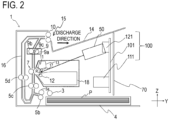
- FIG. 2 is a diagram for describing an internal configuration of the image forming apparatus 1 viewed in the X direction (rotation axial line direction of the photosensitive drum 11).
- the image forming apparatus 1 includes a feeding cassette 4 in which the recording material P is stored, and a discharge tray 14 on which the discharged recording material P is loaded.
- the feeding cassette 4 can be pulled out in the Y direction so that the user can replenish the recording material P.
- An image is formed on the recording material P, which was fed from the feeding cassette 4, and the recording material P is discharged from a discharge port 15 in the discharge direction (Y direction), as indicated in FIG.
- a front cover 70 is provided on a part of the end surface (a part of the front surface) of the image forming apparatus 1 on the downstream side in the discharge direction, so as to cover a later mentioned circuit board 100.
- An exterior cover 71 is provided on the front surface (on a part other than the area where the front cover 70 is provided), and on a side surface and a top surface of the image forming apparatus 1.
- the front cover 70, the exterior cover 71 and the above mentioned discharge tray 14 constitute a housing 720 of the image forming apparatus 1.
- the housing 720 is a member that covers the entire image forming apparatus 1, and includes the later mentioned scanner unit 50 and other process members.
- the above mentioned discharge outlet 15 is an opening that is formed in a part of the housing 720, and the recording material P is discharged out of the image forming apparatus 1 via the discharge port 15.
- the scanner unit 50 emits a laser beam onto the photosensitive drum 11 based on the inputted image information.
- the scanner unit 50 is a unit configured of: a laser oscillator that outputs the laser beam; a polygon mirror and lenses through which the laser beam is emitted onto the photosensitive drum 11; a scanner motor to rotate the polygon mirror; and a frame that integrally supports these members.
- the photosensitive drum 11 is charged in advance by a charging roller 17, and an electrostatic latent image is formed on the photosensitive drum 11 (image bearing member) by the irradiation of the laser beam. Then toner (developer) contained in a container portion 18 is carried to the photosensitive drum 11 (photosensitive member) by a developing roller 12 (developer bearing member), whereby the electrostatic latent image is developed, and a toner image (developer image) is formed on the photosensitive drum 11.
- a later mentioned attached portion 200 for forming a replenishing port, to replenish toner from the outside, is connected to the container portion 18.
- the recording material P is fed from the feeding cassette 4.
- a pickup roller 3 On the conveying path of the image forming apparatus 1, a pickup roller 3, a feeding roller 5a, and a conveying roller pair 5c are provided.
- the pickup roller 3 contacts with the topmost recording material P out of the recording materials P loaded in the feeding cassette 4, and feeds the recording material P by the rotation of the roller.
- the feeding roller 5a and the separation roller 5b separate the plurality of recording materials P so that only the topmost recording material P is fed to the downstream side.
- the recording material P fed from the feeding cassette 4 is conveyed toward a transfer roller 7 via the conveying roller pair 5c.
- the transfer bias applied to the transfer roller 7 the toner image, formed on the photosensitive drum 11, is transferred to the recording material P.
- the recording material P, on which the toner image was transferred by the transfer roller 7, is heated and pressed by a fixing apparatus 9, whereby the toner image is fixed to the recording material P.
- the fixing apparatus 9 is constituted of a heat roller 9a which includes a fixing heater 9c, and a pressure roller 9b which is biased toward the heat roller 9a. Then the recording material P, on which the toner image was fixed, is discharged to the discharge tray 14 via a discharge roller pair 10.
- the discharge roller pair 10 switches back (changes the conveying direction of) the recording material P (on which first surface an image was formed), so as to guide the recording material P to a double-sided conveying path 16.
- the recording material P guided to the double-sided conveying path 16, is conveyed toward the transfer roller 7 again via a double-sided conveying roller pair 5d.
- the recording material P is discharged to the outside via the discharge roller pair 10.
- the toner which remains on the photosensitive drum 11 after the toner image is transferred to the recording material P, is cleaned by a cleaning unit 13.
- the image forming apparatus 1 includes the circuit board 100.
- the circuit board 100 is constituted of a wiring board 101 formed by insulating material, and electronic components 111 and 121 which are soldered to the wiring board 101.
- the electronic components 111 and 121 are electrically connected since conductor wires are formed on and inside the board of the wiring board 101.
- the circuit board 100 has a function to convert AC current supplied from outside the image forming apparatus 1 into DC current, and to convert input voltage so as to acquire a predetermined voltage value required for the image forming process.
- the circuit board 100 is provided so that the surface of the wiring board 101, on which the electronic components 111 and 121 are mounted, intersects with the discharge direction. Further, the wiring board 101 is provided between the front cover 70 and the scanner unit 50 in the discharge direction.
- the electronic components 111 and 121 are provided on the wiring board 101 on the side facing the scanner unit 50.
- FIG. 3 is a perspective view of the image forming apparatus 1 for describing a disposition of the circuit board 100, and unlike FIG. 1 , illustration of the front cover 70 and the exterior cover 71 are omitted.
- an attached portion 200 to replenish the toner is illustrated anew.
- the user or service personnel can replenish developer via the attached portion 200, and the attached portion 200 is connected to the container portion 18 inside the image forming apparatus 1.
- the attached portion 200 will be described in detail later.
- the circuit board 100 is provided on the front surface side, and the scanner unit 50 and a drive motor 60 (drive source) are provided on the rear side (minus side of the Y direction) of the circuit board 100.
- the scanner unit 50 and the drive motor 60 are at positions which cannot be seen, hence are indicated by dotted lines.
- the image forming apparatus 1 includes a right side plate frame 72, a left side plate frame 73, and a base frame 74. The circuit board 100 is supported by these frame members, and is equipped in the image forming apparatus 1 so that the board surface of the circuit board 100 is approximately parallel with the XZ plane.
- bent portions 72a and 73a are formed respectively.
- the bent portion 72a is bent toward the plus side of the X direction so as to be approximately parallel with the XZ plane
- the bent portion 73a is bent toward the minus side of the X direction so as to be approximately parallel with the XZ plane.
- FIG. 4 is a front perspective view of the image forming apparatus 1 for describing a disposition of the circuit board 100.
- a distance L1 between an inner surface of the right side plate frame 72 and that of the left side plate frame 73 in the X direction is shorter than a length L2 of the circuit board 100 in the X direction.
- the wiring board 101 is provided on the plus side (front surface side) of the bent portions 72a and 73a in the Y direction.
- the circuit board 100 and the bent portions 72a and 73a overlap in the front view.
- the bent portions 72a and 73a, the scanner unit 50 and a part of the drive motor 60 are at positions which cannot be seen, hence are indicated by dotted lines.
- the circuit board 100 is provided on the front surface side, and is formed throughout the area from the right side plate frame 72 to the left side plate frame 73, hence in the image forming apparatus 1, there is no need to provide bundle wire, or the like, that crosses between the right side plate frame 72 and the left side plate frame 73 in the X direction.
- the bundle wire length can be shorter than prior arts, and cost can be reduced accordingly.
- the region where the bundle wire is routed is also less than prior arts, which means that electric noise can be reduced as well.
- FIG. 5 is a perspective view of the circuit board 100 viewed from the rear side of the main body.
- the electronic components 111 of which sizes in the Y direction are larger than the other members, are located at the lower part of the wiring board 101, and are mounted so as to be contained below the scanner unit 50, so as to utilize the space efficiently.
- a power supply input portion 115 is provided at the edge of the wiring board 101.
- the power supply input portion 115 is connected to a later mentioned inlet 116, so that power is supplied from a commercial power supply.
- FIG. 6 is a diagram depicting the circuit board 100 viewed from the left side surface of the main body.
- a part of the scanner unit 50 is at a position overlapping with the attached portion 200, and cannot be seen, hence is indicated by a dashed line.
- the scanner unit 50 is provided at an optimum position to emit a laser beam, indicated by a dotted line, to the photosensitive drum 11.
- no members which protrude significantly from the board surface, such as the electronic components 111 are provided.
- the scanner unit 50 and the electronic components 111 are provided shifted from each other in the Z direction, so as not to interfere with each other.
- FIG. 7 is an enlarged top view when the circuit board 100 is viewed from the top surface of the main body.
- the scanner unit 50 and the electronic components 111 are provided at positions that partially overlap with each other.
- the scanner unit 50 is on the upper side of the electronic components 111, as mentioned above, which means that the electronic components 111 cannot be seen in this direction.
- the scanner unit 50 is indicated by a dotted line, as if the electronic components 111 were transparent.
- the drive motor 60 has a function to rotate the conveying members (e.g. pickup roller 3, feeding roller 5a, conveying roller pair 5c) and the photosensitive drum 11, to feed and convey the recording material P.
- conveying members e.g. pickup roller 3, feeding roller 5a, conveying roller pair 5c
- the drive motor 60 projects to the minus side of the X direction, and the wiring board 101 is provided on the front side of the main body with respect to the drive motor 60.
- the electronic components 111 are mounted distant from the drive motor 60, so as not to interfere with the drive motor 60.
- the drive motor 60 and the electronic components 111 are provided at positions that partially overlap with each other when viewed from the left side surface of the main body.
- the drive motor 60 and the electronic components 111 are provided shifted from each other in the X direction when viewed from the top surface of the main body, so as not to interfere with each other.
- FIG. 8 is a perspective view in FIG. 5 , to which the right side plate frame 72 and a scanner holding member 40 are added. Illustration of the left side plate frame 73 and the base frame 74 is omitted here.
- the scanner unit 50 is held by the scanner holding member 40.
- the scanner holding member 40 is fixed to the right side plate frame 72 and the left side plate frame 73 (not illustrated in FIG. 8 ) respectively, and is provided below the attached portion 200 so as to bridge these two frames.
- the drive motor 60 is mounted on the right side plate frame 72, and a gear, connected to the drive motor 60, is provided on the plus side (right side) of the right side plate frame 72 in the X direction.
- the drive force of the drive motor 60 is transferred to the feeding roller 5a and the photosensitive drum 11 via this gear.
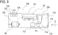
- FIG. 9 is a rear view of the circuit board 100 viewed from the rear side of the main body.
- the circuit board 100 is constituted of the low voltage power supply portion 110 which receives AC power from an external commercial power supply, and converts the AC power into DC power, and a high voltage power supply portion 120 which supplies high voltage required for image formation to each process member.
- the low voltage power supply portion 110 and the high voltage power supply portion 120 are mounted on the same board.
- the low voltage power supply portion 110 includes: a low voltage power transformer 112, a heat sink 113, and an electrolytic capacitor 114 as the electronic components 111 of which sizes in the Y direction are large.
- the low voltage power supply portion 110 also includes the power supply input portion 115.
- the high voltage power supply portion 120 includes a charging transformer 122, a developing transformer 123 and a transferring transformer 124 as the electronic components 121 of which sizes in the Y direction are large. As illustrated in FIG. 9 , the electronic components 111 and 121, of which sizes in the Y direction are large, are all provided distant from the positions of the scanner unit 50, the drive motor 60 and the attached portion 200.
- the connector 220 is connected to a drive motor 60 and sensors (not illustrated) to detect the recording material P in-conveying, for example.
- the connector 221 is connected to a laser output portion (not illustrated) of the scanner unit 50 and a scanner motor (not illustrated) to rotate a polygon mirror.
- the connector 222 is connected to a control panel (not illustrated) which includes a power switch, an execution key, and the like, operated by the user, and a video controller 140.
- the connector 223 is connected to the fixing heater 9c.
- a shaded portion 224 facing the drive motor 60 On a shaded portion 224 facing the drive motor 60, electronic components, of which sizes in the Y direction are small in the high voltage power supply portion 120, are mounted. Specifically, resistors, jumper wires, and the like, are provided. Resistors provided at this position have a function to adjust various biases outputted from the charging transformer 122, the developing transformer 123, and the transferring transformer 124.
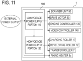
- FIG. 11 is a block diagram for describing the functions of the circuit board 100.
- the low voltage power supply portion 110 receives power from an external power supply via the power supply input portion 115 mounted on the edge of the board, and converts the AC voltage into stable DC voltage by a rectifying/smoothing circuit which includes the electrolytic capacitor 114.
- the low voltage power supply portion 110 converts the DC voltage into high frequency AC voltage using such a switching element as a transistor, and inputs the high frequency AC voltage to the low voltage power transformer 112.
- the low voltage power transformer 112 converts the high frequency AC voltage (input voltage) into AC voltage having a desired voltage value (output voltage).
- the low voltage power supply portion 110 converts the AC voltage into the DC voltage again, and outputs the acquired DC voltage to the high voltage power supply portion 120.
- energy loss of an individual circuit component generates heat, hence the heat sink 113, made of aluminum or iron, is provided to release the heat.
- the high voltage power supply portion 120 convert the voltage supplied rom the low voltage power supply portion 110 (e.g. 24 V) into a high voltage that is required for the image forming process, which includes charging, developing and transferring.
- the charging transformer 122 converts the voltage supplied from the low voltage power supply portion 110 into voltage for charging, and the converted voltage is then supplied to the charging roller 17.
- the developing transformer 123 converts the voltage supplied from the low voltage power supply portion 110 into a voltage for developing, and the converted voltage is then supplied to the developing roller 12.
- the transferring transformer 124 converts the voltage supplied from the low voltage power supply portion 110 into a voltage for transferring, and the converted voltage is then supplied to the transfer roller 7.
- the low voltage power supply portion 110 supplies voltage (e.g. 3.3 V or 5 V) not only to the high voltage power supply portion 120, but also to the scanner unit 50, the drive motor 60, an engine controller 130 and a video controller 140.
- the engine controller 130 has a function to integrally control various process members.
- the engine controller 130 includes a CPU (not illustrated), a RAM (not illustrated) that calculates data required for controlling the image forming apparatus 1 and temporarily stores data, and a ROM (not illustrated) that stores programs and various data to control the image forming apparatus 1.
- the video controller 140 has a function to receive print data by communicating with such an external device as a personal computer, and to notify a result of analyzing the print data to the engine controller 130.
- the engine controller 130 and the video controller 140 may be provided on a board that is different from the circuit board 100, or may be provided on the same board.
- the AC power which the power supply input portion 115 received from a commercial power supply, is supplied not only to the low voltage power supply portion 110, but also to the fixing heater 9c.
- a triac (not illustrated) is provided between the power supply input portion 115 and the connector 223, and the temperature of the fixing heater 9c can be adjusted by switching the triac ON/OFF, so as to change the sine wave.
- Driving of the roller and the like in the fixing apparatus 9 is performed by the drive motor 60.
- the attached portion 200 will be described with reference to FIGS. 12 to 22 .
- the attached portion 200 which replenishes toner from an outside source when the residual amount of toner in the container portion 18 is low, is provided so that the container portion 18 need not be detached from the housing 720.
- the attached portion 200 which is a toner container (developer container)
- a replenishing pack 210 can be detached/attached.
- FIG. 12 is a left side view of the image forming apparatus 1 viewed in the rotation axial line direction of the photosensitive drum 11.
- the attached portion 200 is constituted of: a mounting portion 201 where the replenishing pack 210 (not illustrated in FIG. 12 ) is mounted; a toner-receiving portion 202 which is a cylindrical-shaped frame; and a replenishing path portion 203 that connects the container portion 18 and the toner-receiving portion 202.
- the mounting portion 201 includes a replenishing port 204, which is an opening to replenish toner, and is configured such that the toner which passed through the replenishing port 204 moves on to the toner-receiving portion 202 and the replenishing path portion 203 sequentially, and is finally supplied to the container portion 18.
- a part of the scanner unit 50 is at a position which overlaps with the attached portion 200, and cannot be seen, hence this region is indicated by a dotted line in FIG. 12 .
- the toner-receiving portion 202 and the replenishing path portion 203 of the attached portion 200 overlap with the scanner unit 50.
- the toner-receiving portion 202 and the replenishing path portion 203 are at positions overlapping with the scanner unit 50 in the Z direction.
- R1 is a region where the replenishing port 204 is provided in the Y direction (horizontal direction)
- R2 is a region where the scanner unit 50 is provided in the Y direction
- S is a virtual plane that passes through an upper edge 18b, which is located at the uppermost side of a frame 18a of the container portion 18, and is parallel with the horizontal plane.
- the virtual plane S is indicated by dashed lines in FIG. 12 . If the virtual plane S is a reference, then a part of the attached portion 200 is located at the plus side (upper side) in the Z direction. In other words, a part of the attached portion 200 projects upward from the upper edge 18b of the container portion 18.
- a part of the attached portion 200 includes the entire mounting portion 201, a part of the toner-receiving portion 202, and a part of the replenishing path portion 203. The part of the toner-receiving portion 202 and the part of the replenishing path portion 203, which project upward from the virtual plane S, overlap with the scanner unit 50.
- a part of the container portion 18 is at a position overlapping with a drum frame 11a that supports the photosensitive drum 11, and cannot be seen, hence this region is indicated by a dotted line.
- the container portion 18 supports the developing roller 12 which bears the developer, and this developing roller 12 is also at a position that cannot be seen, hence is indicated by a dotted line in FIG. 12 .
- FIG. 13 is a top view of the image forming apparatus 1 when the exterior cover 71 is removed.
- the mounting portion 201 includes the replenishing port 204.
- the mounting portion 201 also includes a ring portion 201a which is provided to surround the replenishing port 204, and a lever portion 201b which is connected to the ring portion 201a.
- the width of the attached portion 200 in the X direction is shorter than the width of the container portion 18 in the X direction.
- the laser beam emitted from the scanner unit 50 onto the photosensitive drum 11 spreads in a trapezoidal shape, as illustrated in FIG. 13 , due to the functions of the polygon mirror and the lens (neither illustrated). Therefore the width of the scanner unit 50 in the X direction is shorter than the width of the photosensitive drum 11. As a result, a space is created between the left end of the scanner unit 50 and the left side plate frame 73, and in the present embodiment, the attached portion 200 is provided in this space. In other words, the attached portion 200 is provided between the scanner unit 50 and the left side plate frame 73 in the X direction, as illustrated in FIG. 13 .
- the replenishing port 204 and the scanner unit 50 are provided side-by-side in the X direction, in a region where the container portion 18 is provided. If the attached portion 200 is provided at this position, the size of the image forming apparatus 1 is little influenced by disposing the attached portion 200.
- the attached portion 200 is provided on opposite sides of the drive motor 60 with respect to the scanner unit 50.
- the drive motor 60 used in the present embodiment is relatively small, hence as illustrated in FIG. 12 , the attached portion 200 and the drive motor 60 do not overlap in the Z direction. Therefore it is possible to provide the attached portion 200 and the drive motor 60 on the same side with respect to the scanner unit 50, but in the case of using a larger drive motor 60, the attached portion 200 must be provided at an upper position, which increases the size of the image forming apparatus 1. If the configuration where the attached portion 200 is provided on the opposite side of the drive motor 60 is used, as described in the present embodiment, a larger drive motor 60 can be used without increasing the size of the image forming apparatus 1. In other words, design flexibility can be improved.
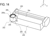
- FIG. 14 is a perspective view of a developer container 230 constituted of the container portion 18 and the attached portion 200.
- illustration of a part of members associated with the attached portion 200 is omitted.
- On the inner wall of the cylindrical-shaped toner-receiving portion 202 a side surface opening 205, which is connected to the replenishing path portion 203, is formed, but the side surface opening 205 is covered by a main body shutter portion 206 and cannot be seen, hence is indicated by dotted lines. Toner is guided from the toner-receiving portion 202 to the replenishing path portion 203 via this side surface opening 205, and is then contained in the container portion 18 via the replenishing path portion 203.
- On the main body shutter portion 206 a main body shutter portion driving transfer rib 206a is provided and used to receive driving force for the replenishing pack 210, and to rotate the main body shutter portion 206 (details described later).
- FIGS. 15A to 15C are enlarged perspective views of the attached portion 200
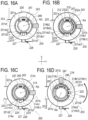
- FIGS. 16A to 16D are enlarged cross-sectional views of the mounting portion 201 viewed from the top surface.
- the side surface opening 205 formed in the toner-receiving portion 202 is covered by the main body shutter portion 206, and cannot be seen, hence is indicated by a dotted line.
- the main body shutter portion 206 is a cylindrical-shaped member which is concentric with the toner-receiving portion 202, and is provided at the inside of the toner-receiving portion 202.
- An opening 207 for the toner to pass though is also formed in the main body shutter portion 206.
- the side surface opening 205 and the opening 207 are provided at positions that are shifted from each other, hence the side surface opening 205 is closed.
- the mounting portion 201 is provided in a top surface portion 240 (not illustrated), so as to be concentric with the toner-receiving portion 202, and is restricted in the rotating direction by a later mentioned lever lock mechanism when the replenishing pack 210 is not attached.
- This lever mechanism can prevent a shift in phases of a mounting portion driving transfer rib 201d and the main body shutter portion driving transfer rib 206a before attaching the replenishing pack 210, so that the replenishing pack 210 can be attached with certainty.
- a lever lock release rib 214a which is a release portion provided in pack shutter portion 214 (shutter member), is inserted into a lock release recessed portion 201f.
- the lever lock release rib 214a is a projecting portion that projects from an outer surface of the pack shutter portion 214, which extends in the rotation axial line direction, in a direction intersecting with the rotation axial line.
- a state of engagement between a guided portion 232 of an inserting portion 212 (discharging portion engaging portion) and a guiding portion 247 (248) of the toner-receiving portion 202 (frame engaged portion) is as illustrated in FIG. 16B .
- the relative movement between the inserting portion 212 and the toner-receiving portion 202, in the circumferential direction centering the rotation axial line of the pack shutter portion 214, can be mutually restricted. Details will be described later.
- the mounting portion driving transfer rib 201d is engaged with the main body shutter portion driving transfer rib 206a via a pair of driving transfer surfaces 214b of the pack shutter portion 214 of the replenishing pack 210.
- the mounting portion driving transfer rib 201d is a protruded portion (rotting member protruded portion) that extends from an inner peripheral surface, centering the rotation axial line R of a hole formed in the approximately annular mounting portion 201, to the rotation axial line RA.
- the mounting portion driving transfer rib 201d includes a first engaging portion 201d1 and a second engaging portion 201d2, which are portions to form a first projected portion side surface 201ds1 and a second projected portion side surface 201ds2, and which are arranged across a projected portion front end surface 201dt in the circumferential direction centering the rotation axial line RA.
- the main body shutter portion driving transfer rib 206a is a projected portion (shutter convex portion) that extends from the inner peripheral surface, centering the rotation axial line R of the hole formed in the approximately cylindrical main body shutter portion 206, to the rotation axial line RA.
- the main body shutter portion driving transfer rib 206a includes a first shutter projected portion side face 206a1 and a second shutter projected portion side surface 206a2, which are arranged across a shutter projected portion front end surface 206at in the circumferential direction centering the rotation axial line RA.
- the main body shutter portion 206 can be rotated inside the toner-receiving portion 202 by the user holding the lever portion 201b and moving the lever portion 201b from the state in FIGS. 15B and 16C to the state in FIGS. 15C and 16D .
- the side surface opening 205 and the opening 207 are at overlapping positions, hence the side surface opening 205 is opened, and toner can be replenished through the side surface opening 205.
- the side surface opening 205 must be shut off (closed) so that the toner being stirred in the container portion 18 by the stirring member (not illustrated) does not leak through the side surface opening 205.
- the lever portion 201b is moved to the position indicated in FIGS. 15A and 16A .
- This position is referred to as an initial position or operation position of the lever portion 201b.
- the side surface opening 205 must be opened.
- the lever portion 201b is moved to the position indicated in FIGS. 15C and 16D . This position is referred to as a replenishing position of the lever portion 201b.
- the size of the lever portion 201b is as large as possible, so that the user can hold the lever portion 201b easily.
- the configuration of the operation portion for the user to open/close the shutter is not limited to the configuration using the lever portion 201b. Various configurations may be used as long as at least a part of the mounting portion 201 is exposed in a state where the replenishing pack 210 is mounted so that the user can operate the part.
- the circuit board 100 is provided on the front side (plus side of Y direction) of the attached portion 200, and in the present embodiment, the attached portion 200 and the circuit board 100 are provided in proximity to each other in order to downsize the image forming apparatus 1 in the Y direction. Therefore, as illustrated in FIGS.
- FIG. 22 is a perspective view viewed from the rear side of the main body
- FIG. 23 is a top view.
- the position corresponding to the notch 101a is indicated by a dotted line.
- the lever portion 201b in the initial position overlaps with the wiring board 101.
- the notch 101a is formed at a position corresponding to the rotation locus of the lever portion 201b.
- the notch 101a is formed on the wiring board 101, but interference with the lever portion 201b may be prevented by forming a through hole or a groove in the wiring board 101.
- FIGS. 19A, 19B , 20A to 20C , 21A, and 21B The configuration of receiving replenishment of the developer in the image forming apparatus or the image forming system according to the present embodiment will be described in detail with reference to FIGS. 19A, 19B , 20A to 20C , 21A, and 21B .
- FIGS. 19A and 19B are exploded perspective view of the attached portion 200.
- FIGS. 19A and 19B are perspective views viewed from different directions.
- FIGS. 20A to 20C are perspective views of the attached portion 200, and unlike FIGS. 15A to 15C , illustration of the replenishing pack 210, a lever lock member 227 and a lever lock portion pressing spring 228 is omitted.
- FIGS. 20A and 20C indicate a state where the mounting portion 201 (opening/closing member) is at a closed function position viewed from different perspective directions.
- the mounting portion 201 is provided so as to be located outside the pack shutter portion 214 in the radius direction r of a virtual circle VC, centering the rotation axial line RA, when the mounting portion 201 is viewed in the rotation axial line direction in the state where the replenishing pack 210 is attached.
- FIG. 20B indicates a state where the mounting portion 201 is at an open function position.
- the main body shutter portion 206 (apparatus shutter) is provided on the inside of the toner-receiving portion 202 (developer-receiving portion).
- the main body shutter portion 206 includes the opening 207 (apparatus opening) to form a communication hole to replenish toner, and a sealing member 243 is adhered to the inner peripheral surface of the main body shutter portion 206, so as to surround the outer periphery of the opening 207.
- the sealing member 243 contacts with the outer surface of the inserting portion 212, particularly around the opening 213, and seals the later mentioned communication hole 245.
- guiding portions 247 and 248 frame engaged portions that guide a guided portion 232 (discharging portion engaging portion) of the inserting portion 212 of the replenishing pack 210 are provided.
- the main body shutter portion driving transfer rib 206a which guides a positioning portion 217 (a guided portion of the pack shutter portion 214 (cylindrical container shutter) is also provided on the inner peripheral surface of the main body shutter portion 206.
- a mounting portion 201 (opening/closing member) is rotatably mounted.
- the mounting portion driving transfer rib 201d which projects inward from the inner peripheral surface side of the mounting portion 201, is also a guiding portion that guides the positioning portion 217 of the pack shutter portion 214.
- the guided portion 232 can be engaged with the guiding portions 247 and 248, and the positioning portion 217 can be engaged with the mounting portion driving transfer rib 201d and the main body shutter portion driving transfer rib 206a.
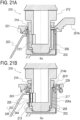
- FIGS. 21A and 21B are schematic cross-sectional views of the replenishing pack 210 and the attached portion 200.
- FIG. 21A indicates a state where the mounting portion 201 is at the close function position, and each shutter is at the close position.
- the opening 213 (container opening) is closed by the sealing member 231 provided on the inner peripheral surface of the pack shutter 214, and the side surface opening 205 (receiving port) is closed by the main body shutter portion 206.
- FIG. 21B indicates a state where the mounting portion 201 is at the open function position, and each shutter is at the open position.
- the opening 213 and the receiving port 205 communicate through a communication hole 245, which is formed by the opening 207 provided in the main body shutter portion 206, and the opening 244 of the sealing member 243, provided on the inner peripheral surface of the main body shutter portion 206 so as to surround the opening 207.
- this is a state where toner (developer) can be replenished from the replenishing pack 210 (developer container) to the image forming apparatus 1.
- the replenishing pack 210 includes: a pouch portion 211 containing toner to be replenished; a discharging portion (nozzle portion, pipe, tube, valve) 212 that is a cylindrical-shaped inserting portion to be inserted into the replenishing port 204 that discharges the toner inside the pouch portion; an opening 213 that is formed on the side surface of the inserting portion 212 for the toner to pass through; and the pack shutter portion 214 that covers the opening 213 to prevent the leakage of toner.
- the pouch portion 211 is formed to be flatter in the direction toward the opposite side of the inserting portion 212, and a pouch edge 216, extending in a predetermined direction, is formed on the edge.
- the pouch portion 211 is a pouch formed by performing pouch processing on a flexible polypropylene sheet, but the container portion of the toner is not limited to a pouch, and may be a resin bottle, a paper or vinyl container, or the like.
- FIG. 18A a pack shutter portion opening 214c is formed on the pack shutter portion 214.
- FIG. 18B is a view of the replenishing pack 210 viewed from an angle different from FIG. 18A .
- the opening 213 formed in the inserting portion 212 is covered by the pack shutter portion 214, and cannot be seen, hence is indicated by a dotted line.
- the pack shutter portion 214 is a cylindrical-shaped member that is concentric with the inserting portion 212, and is rotatably provided at the outer side (at outer periphery) of the inserting portion 212.
- a positioning portion 217 On the outer peripheral surface of the pack shutter portion 214, a positioning portion 217, which engages with the mounting portion 201 and the driving transfer surfaces 214b, which face each other via the positioning portion 217 in the circumferential direction of the outer periphery of the pack shutter portion 214, are provided.
- a groove (a recessed portion that is recessed inward from the outer peripheral surface of the pack shutter portion 214 in the radius direction r of a virtual circle VC), which is constituted of the positioning portion 217 as a groove bottom surface (recessed portion bottom surface) and the driving transfer surfaces 214b as groove side surfaces, is formed.
- This groove is open at the front end portion of the outer peripheral surface of the pack shutter portion 214 in the inserting direction of the inserting portion 212.
- the pack shutter portion 214 is rotated with respect to the inserting portion 212 by the driving transfer surfaces 214b receiving force in the circumferential direction from the mounting portion driving transfer rib 201d.
- a rib 214a to release the lever lock mechanism of the mounting portion 201.
- FIGS. 17A to 17C are exploded perspective views of the replenishing pack 210.
- FIGS. 17A to 17C are perspective views viewed from different directions.
- a pack shutter portion opening 214c provided in the pack shutter portion 214, and the guided portion 232 provided so as to be recessed from the outer peripheral surface of the inserting portion 212, overlap with each other in the rotation phase in the circumferential direction.
- the replenishing pack 210 is in a state where the guided portion 232 is engaged with and guided by the guiding portions 247 and 248, and the pack shutter portion opening 214c is engaged with the periphery of the sealing member 243 provided on the inner peripheral surface of the main body shutter portion 206.
- a first guided portion 232a (on the upstream side in the inserting direction) of the guided portion 232 engages with the guiding portion 247
- a second guided portion 232b (on the downstream side in the inserting direction) engages with the guiding portion 248.
- a surface (step difference portion) extending in the circumferential direction between the first guided portion 232a and the second guided portion 232b, engages in the inserting direction with a surface (step difference portion) between the guiding portion 247 and the guiding portion 248, extending in the circumferential direction, and determines a position in the inserting direction between the inserting portion 212 and the mounting portion 201.
- the pack shutter portion opening 214c is a notch-shaped opening, of which width increases in a direction toward the front end of the inserting portion 212.
- a pair of facing portions, which form the pack shutter portion opening 214c and face each other in the circumferential direction, are provided on each side of the sealing member 243 in the circumferential direction.
- a driving transfer surface 214b of the pack shutter portion 214 engages with the mounting portion 201 (rotating member) in the pack shutter portion 214, and as the open/close engaging portion, the driving transfer surface 214b engages with the main body shutter portion 206 in the pack shutter portion 214.
- the pack shutter portion 214 is moved (rotated) together with the mounting portion 201 by the control (operation) force of the mounting portion 201, and transfers this control force to the main body shutter portion 206, so as to move the main body shutter portion 206 as well.
- the driving transfer surface 214b has a region that engages and contacts with the mounting portion driving transfer rib 201d (rotating member engaged portion).
- the driving transfer surface 214b includes: a first shutter engaging portion 218b 1 that is a part of a first groove side surface 214b 1 (first recessed portion side surface), out of the pair of groove side surfaces of the groove-shaped portion; and a second shutter engaging portion 218b2 that is a part of a second groove side surface 214b2 (second recessed portion side surface) thereof.
- the mounting portion driving transfer rib 201d includes: a first engaging portion 201d1 (first rotating member engaged portion) that engages with the portion 218b 1 of the driving transfer surface 214b in one circumferential direction around the rotation axial line; and a second engaging portion 201d2 (second rotating member engaged portion) that engages with the portion 218b2 of the driving transfer surface 214b in the other circumferential direction.
- Each engaging portion 201d1 and 201d2 of the mounting portion driving transfer rib 201d has a protruded shape that extends from the inner peripheral surface of the annular mounting portion 201, centering the rotation axial line RA, toward the rotation axial line RA side.
- the driving transfer surfaces 214b include a region that engages and contacts with the main body shutter portion driving transfer rib 206a (open/close engaged portion).
- the driving transfer surfaces 214b include a portion (first open/close engaging portion) 219b 1 provided at a position (downstream side in the inserting direction), which is different from the first shutter engaging portion 218b 1 on the first groove side surface in the rotation axial line RA direction, and a portion (second open/close engaging portion) 219b2 provided at a position (downstream side in the inserting direction) which is different from the second shutter engaging portion 218b2 of the second groove side surface in the rotation axial line RA direction.
- the main body shutter portion driving transfer rib 206a includes a first shutter protruded portion side surface 206a1 which is a portion (first open/close engaged portion) that engages with the portion 219b 1 of the driving transfer surfaces 214b in one circumferential direction, and a second shutter protruded portion side surface 206b2 which is a portion (second open/close engaged portion) that engages with the portion 219b2 of the driving transfer surfaces 214b in the other circumferential direction.
- FIG. 24 is a perspective view depicting the rotation restricting mechanism of the present embodiment, where only the lever lock member 227 (restricting member), the lever lock release link 229 (release member) and the lever lock portion pressing spring 228 (biasing member of the restricting return portion) are illustrated.
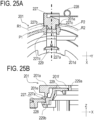
- FIGS. 25A and 25B are a bottom view and a cross-sectional view of the mounting portion 201 and the lever lock mechanism when the lever lock member 227 is at the restricting position (locked state).
- FIGS. 26A and 26B are a bottom view and a cross-sectional view of the mounting portion 201 and the lever lock mechanism when the lever lock member 227 is at an allowable position (lock released state).
- the inner wall of the opening 201e contacts and engages with the rotation restricting surfaces 227b and 227c (restricting portions) which are surfaces perpendicular to the rotating direction, whereby rotation of the mounting portion 201 is restricted.
- the lever lock release link 229 has an inclined surface shape 229a that contacts with the lever lock release rib 214a and functions as a contact activating portion.
- the lever lock release link 229 receives a force to move the lever lock member 227 to a pressing position (a position that is moved to the lever lock release position) from the pack shutter portion 214 via the inclined surface shape 229a and the lever lock release rib 214a.
- the inclined surface shape 229a has a shape that is inclined toward the direction where the replenishing pack 210 is inserted into the mounting portion 201.
- the inclined surface shape 229a is a shape that is inclined so that the force received from the lever lock release rib 214a includes the component force that acts in the direction of moving the lever lock release link 229 to the pressing position.
- the lever lock release link 229 is pressed in the arrow direction by the force that the inclined surface shape 229a (pressed portion) receives from the lever lock release rib 214a, and the edge, where the inclined surface shape 229a is formed, rises over the side surface of the lever lock release rib 214a.
- the lever lock release link 229 moves to the pressing position where the contact surface 229b (pressing portion) moves the lever lock member 227 to the lever lock release position.
- the lever lock member 227 which is in contact with the lever lock release link 229, moves to the lever lock release position in the arrow direction against the biasing force of the lever lock portion pressing spring 228.
- the assembling phase of the mounting portion 201 is set to the direction in which rotation is restricted, whereby both the prevention of the rotation to the assembling phase direction after assembly and the rotation up to the replenishing position are implemented.
- FIGS. 27A to 27E indicate a flow from the initial position of the lock mechanism to the replenishing position.
- P1 and P2 are on the inside of the rotation loci R1 and R2, and the rotation of the mounting portion 201 is restricted thereby, as described above.
- FIG. 27B when the replenishing pack 210 is attached, the lever lock member 227 is retracted, and the mounting portion 201 can be rotated in the arrow direction, as described above.
- FIG. 27C indicates the state where the lock member 227 is retracted, and the inclined surface 227d completely rises over the opening 201e.
- the lock member 227 and the lever lock release link 229 are in relative positions, and do not contact with each other (separated state), as illustrated in FIG. 27D , and the lock member 227 contacts with the outer surface of the mounting portion 201, and is maintained in the rotation allowable position. Since the lock member 227 does not interfere with the rotation of the mounting portion 201 in this state, the user can move the lever portion 201b to the replenishing position. If the mounting portion 201 is rotated to the replenishing position, as illustrated in FIG. 27E , the lever lock pressing portion 227a enters the replenishing position recessed portion 201h of the mounting portion 201, where an audible sound or operation force changes. Thereby, the user can easily recognize that the lever portion 201b has been move to the replenishing position.
- FIGS. 28A and 28B are perspective views of the image forming apparatus 1.
- FIG. 28A indicates a state in which the discharge tray 14 covers the attached portion 200, and is at a position where the recording material P, discharged from the discharge outlet 15, can be loaded.
- FIG. 28B indicates a state in which the discharge tray 14 is at a position where the attached portion 200 is exposed from the discharge tray 14.
- the discharge tray 14 is configured to be movable to the position where the recording material P can be loaded, as indicated in FIG. 28A , and the position where the attached portion 200 is exposed, as indicated in FIG. 28B .
- the attached portion 200 is provided at an upper part of the front surface of the image forming apparatus 1, hence the user has easy access to the portion when toner is replenished.
- the recording material P loaded on the discharge tray 14, is removed, and the discharge tray 14 at the loadable position indicated in FIG. 28A , is opened to be moved to the expose position indicated in FIG. 28B .
- the discharge tray 14 is opened, the attached portion 200 and a top surface portion 240, which adjoins the attached portion 200, is exposed.
- the replenishing pack 210 is inserted into the exposed attached portion 200.
- the replenishing pack 210 is inserted such that the position of the mounting portion driving transfer rib 201d ( FIG. 19B ), which is provided in the attached portion 200, matches with the position of the positioning portion 217 ( FIG. 18B ) provided in the replenishing pack 210. If the positions of the mounting portion driving transfer rib 201d and the positioning portion 217 do not match, the replenishing pack 210 interferes with the mounting portion driving transfer rib 201d, and the replenishing pack 210 cannot be attached.
- the phases of the replenishing pack 210 and the mounting portion 201 can, in a visual sense, be easily matched when the replenishing pack 210 is attached.
- FIG. 29A indicates a state where the replenishing pack 210 is inserted into the attached portion 200.
- the replenishing pack 210 can be inserted when the direction D, in which the pouch edge 216 extends, is parallel with the X direction.
- the main body shutter portion driving transfer rib 206a FIG. 14
- the main body shutter portion driving transfer rib 206a FIG. 14
- the positioning portion 217 FIGS. 18A and 18B
- the rib 206a faces the positioning portion 217 in the radius direction, and is inserted between the driving transfer surfaces 214b, whereby the main body shutter portion 206 and the pack shutter portion 214 are engaged and integrated.
- the main body shutter portion 206 and the pack shutter portion 214 can be rotated in tandem by the operation of the lever portion 201b.
- FIG. 29B indicates a state where the lever portion 201b is moved from the initial position to the replenishing position.
- the replenishing pack 210 in the Z direction is fixed to the attached portion 200 by a replenishing pack retaining mechanism (not illustrated).
- the pack shutter portion 214 provided in the replenishing pack 210, is rotated by moving the lever portion 201b.
- the main body shutter portion 206 of the attached portion 200 is rotated with the pack shutter portion 214 since the main body shutter portion 206 and the pack shutter portion 214 are engaged.
- the side surface opening 205 FIGS.
- the opening 213 ( FIGS. 18A and 18B ), which is formed in the inserting portion 212, opens.
- the side surface opening 205 formed in the toner-receiving portion 202 and the opening 213 formed in the inserting portion 212 are in such a positional relationship that the side surface opening 205 and the opening 213 face each other at the point when the replenishing pack 210 is inserted into the attached portion 200. Therefore when the lever portion 201b is moved from the initial position to the replenishing position, the replenishing pack 210, the attached portion 200 and the container portion 18 are connected, and the toner can be replenished.
- FIG. 30 indicates a top view when the state in FIG. 29B is viewed from the top.
- the direction D extending from the pouch edge 216 is parallel with the X direction, as mentioned above.
- a protruded portion 241 which protrudes in the plus side of the Z direction (upper side) is formed.
- the notch 242 is formed in a part of the protruded portion 241, and the position where the notch 242 is formed corresponds to the rotation locus of the lever portion 201b.
- the lever portion 201b at the initial position is indicated by a dotted line.
- the lever portion 201b is returned to the original position (initial position).
- both the main body shutter portion 206 of the attached portion 200 and the pack shutter portion 214 of the replenishing pack 210 rotate first, then both the side surface opening 205 and the opening 213 thereof close respectively.
- the retention of the attached portion 200 and the replenishing pack 210 is released, and the replenishing pack 210 can be detached from the attached portion 200.
- the pack shutter portion 214 is in the closed state unless the replenishing pack 210 is inserted into the attached portion 200 of the image forming apparatus 1, and leaking of toner can be prevented.
- the lock release recessed portion 201f of the mounting portion 201 used for the lever lock mechanism is formed to be larger compared with the lock release rib 214a of the replenishing pack 210, and the lever lock mechanism can be released even if the positions of the lock release recessed portion 201f and the lock release rib 214a deviate somewhat. Therefore in Embodiment 2, as illustrated in FIG. 31A and 31B , the positional relationship of the lock release recessed portion 201f and the lock release rib 214a is designed such that only a compatible combination is allowed, so that an attachment error by the user can be prevented.
- FIG. 31A indicates a first replenishing pack 210A with which the lock release recessed portion 201f and the lock release rib 214a do not interfere with each other.
- the first replenishing pack 210A is at such a relative position that various guide portions of the first replenishing pack 210A can be engaged with the attached portion 200, and a lock release rib 214aA can be guided by a lock release recessed portion 201f (guide portion).
- FIG. 31B indicates a second replenishing pack 201B with which a lock release rib 214aB is provided at a position that is different from the lock release rib 214aA.
- the engaging positions of various guide portions of the second replenishing pack 210B are the same as the first replenishing pack 201A, but the position of the lock release rib 214aB is at a position where engaging with the lock release recessed portion 201f is not allowed, hence the second replenishing pack 210B contacts with the mounting portion driving transfer rib 201d, which is adjacent to the lock release recessed portion 201f, and forms a wall portion (attachment restricting portion). Thereby the second replenishing pack 210B is restricted not to be attached to the attached portion 200.
- the phases of the replenishing container 210 and the mounting portion 201, when the replenishing pack 210 is attached, are determined by the engagement of the positioning portion 217 and the mounting portion driving transfer rib 201d, hence if the position of the lock release rib 214a is different, the lock release rib 214a interferes with the mounting portion driving transfer rib 201d, whereby the replenishing pack 210 cannot be completely attached. Therefore by disposing a lock release rib 214a at a different position in the replenishing pack 210 filled with incompatible toner, an attachment error by the user can be prevented.
- An attached portion of an image forming apparatus includes: a rotating member of which at least a part is exposed outside the image forming apparatus when the developer container is attached; and a rotation restricting mechanism that is movable between a restricting position to restrict rotation of the rotating member and an allowable position to allow rotation of the rotating member, and includes a restricting member that is at the restricting position when the developer container is not attached.
- the developer container is attached to the attached portion so that the discharging portion engaging portion and the shutter engaging portions are engaged with the frame engaged portions and the rotating member engaged portions respectively when the container shutter is in the close state, and the restricting member moves from the restricting position to the allowable position when the developer container is attached to the attached portion.
Landscapes
- Physics & Mathematics (AREA)
- General Physics & Mathematics (AREA)
- Life Sciences & Earth Sciences (AREA)
- Sustainable Development (AREA)
- Electrophotography Configuration And Component (AREA)
- Dry Development In Electrophotography (AREA)
Applications Claiming Priority (2)
| Application Number | Priority Date | Filing Date | Title |
|---|---|---|---|
| JP2020218436A JP7614839B2 (ja) | 2020-12-28 | 2020-12-28 | 画像形成装置 |
| EP21217826.3A EP4020089B1 (de) | 2020-12-28 | 2021-12-27 | Bilderzeugungssystem |
Related Parent Applications (2)
| Application Number | Title | Priority Date | Filing Date |
|---|---|---|---|
| EP21217826.3A Division-Into EP4020089B1 (de) | 2020-12-28 | 2021-12-27 | Bilderzeugungssystem |
| EP21217826.3A Division EP4020089B1 (de) | 2020-12-28 | 2021-12-27 | Bilderzeugungssystem |
Publications (2)
| Publication Number | Publication Date |
|---|---|
| EP4411487A2 true EP4411487A2 (de) | 2024-08-07 |
| EP4411487A3 EP4411487A3 (de) | 2024-11-06 |
Family
ID=79025166
Family Applications (2)
| Application Number | Title | Priority Date | Filing Date |
|---|---|---|---|
| EP21217826.3A Active EP4020089B1 (de) | 2020-12-28 | 2021-12-27 | Bilderzeugungssystem |
| EP24177282.1A Pending EP4411487A3 (de) | 2020-12-28 | 2021-12-27 | Bilderzeugungssystem |
Family Applications Before (1)
| Application Number | Title | Priority Date | Filing Date |
|---|---|---|---|
| EP21217826.3A Active EP4020089B1 (de) | 2020-12-28 | 2021-12-27 | Bilderzeugungssystem |
Country Status (4)
| Country | Link |
|---|---|
| US (4) | US11526099B2 (de) |
| EP (2) | EP4020089B1 (de) |
| JP (2) | JP7614839B2 (de) |
| CN (1) | CN114690602B (de) |
Families Citing this family (5)
| Publication number | Priority date | Publication date | Assignee | Title |
|---|---|---|---|---|
| KR20240011474A (ko) * | 2022-07-19 | 2024-01-26 | 휴렛-팩커드 디벨롭먼트 컴퍼니, 엘.피. | 현상 카트리지의 셔터 잠금 구조 |
| JP7331220B1 (ja) | 2022-08-05 | 2023-08-22 | キヤノン株式会社 | 画像形成装置 |
| JP2024033622A (ja) | 2022-08-30 | 2024-03-13 | キヤノン株式会社 | 画像形成装置 |
| JP2024057526A (ja) | 2022-10-12 | 2024-04-24 | キヤノン株式会社 | 現像装置及び画像形成装置 |
| JP2024077597A (ja) | 2022-11-28 | 2024-06-07 | キヤノン株式会社 | 画像形成装置 |
Citations (2)
| Publication number | Priority date | Publication date | Assignee | Title |
|---|---|---|---|---|
| WO2020045764A1 (en) * | 2018-08-30 | 2020-03-05 | Hewlett-Packard Development Company, L.P. | Interface structure for toner refill cartridge and toner refill portion |
| JP2020154300A (ja) | 2019-03-15 | 2020-09-24 | キヤノン株式会社 | 画像形成装置 |
Family Cites Families (13)
| Publication number | Priority date | Publication date | Assignee | Title |
|---|---|---|---|---|
| JP2986679B2 (ja) * | 1994-06-17 | 1999-12-06 | シャープ株式会社 | トナーカートリッジ |
| JP3467650B2 (ja) * | 1994-12-27 | 2003-11-17 | セイコーエプソン株式会社 | トナー補給容器 |
| US5848338A (en) * | 1997-01-17 | 1998-12-08 | Mita Industrial Co., Ltd. | Toner replenishing device and toner cartridge for use therein |
| JP3298065B2 (ja) * | 1997-01-17 | 2002-07-02 | 京セラミタ株式会社 | トナー補給装置及びそれに使用されるトナーカートリッジ |
| US6269234B1 (en) * | 1999-09-29 | 2001-07-31 | Xerox Corporation | Locking member for refillable print cartridge/toner bottle strategy |
| JP3714161B2 (ja) | 1999-12-27 | 2005-11-09 | カシオ電子工業株式会社 | 画像形成装置 |
| US6363235B1 (en) | 2001-01-31 | 2002-03-26 | Xerox Corporation | Toner bottle/cartridge housing attachment assembly |
| JP2004133191A (ja) | 2002-10-10 | 2004-04-30 | Kyocera Corp | 現像装置 |
| JP5889359B2 (ja) | 2014-04-21 | 2016-03-22 | キヤノン株式会社 | 画像形成装置 |
| JP2020101687A (ja) | 2018-12-21 | 2020-07-02 | キヤノン株式会社 | 現像装置、プロセスカートリッジ及び画像形成装置 |
| JP7230527B2 (ja) * | 2019-01-22 | 2023-03-01 | 京セラドキュメントソリューションズ株式会社 | トナー容器及び画像形成装置 |
| JP2020158911A (ja) * | 2019-03-26 | 2020-10-01 | セイコーエプソン株式会社 | 添加剤収容具 |
| US11402767B2 (en) * | 2020-02-07 | 2022-08-02 | Canon Kabushiki Kaisha | Image forming apparatus |
-
2020
- 2020-12-28 JP JP2020218436A patent/JP7614839B2/ja active Active
-
2021
- 2021-12-22 US US17/558,762 patent/US11526099B2/en active Active
- 2021-12-27 CN CN202111611942.XA patent/CN114690602B/zh active Active
- 2021-12-27 EP EP21217826.3A patent/EP4020089B1/de active Active
- 2021-12-27 EP EP24177282.1A patent/EP4411487A3/de active Pending
-
2022
- 2022-11-03 US US17/979,815 patent/US12038700B2/en active Active
-
2024
- 2024-02-15 US US18/442,289 patent/US12405553B2/en active Active
- 2024-12-26 JP JP2024229814A patent/JP7844615B2/ja active Active
-
2025
- 2025-08-04 US US19/289,360 patent/US20250362628A1/en active Pending
Patent Citations (2)
| Publication number | Priority date | Publication date | Assignee | Title |
|---|---|---|---|---|
| WO2020045764A1 (en) * | 2018-08-30 | 2020-03-05 | Hewlett-Packard Development Company, L.P. | Interface structure for toner refill cartridge and toner refill portion |
| JP2020154300A (ja) | 2019-03-15 | 2020-09-24 | キヤノン株式会社 | 画像形成装置 |
Also Published As
| Publication number | Publication date |
|---|---|
| US20220206412A1 (en) | 2022-06-30 |
| US12405553B2 (en) | 2025-09-02 |
| US20230048810A1 (en) | 2023-02-16 |
| JP2025038234A (ja) | 2025-03-18 |
| CN114690602B (zh) | 2026-04-17 |
| JP7614839B2 (ja) | 2025-01-16 |
| EP4020089B1 (de) | 2024-07-03 |
| JP7844615B2 (ja) | 2026-04-13 |
| CN114690602A (zh) | 2022-07-01 |
| US20250362628A1 (en) | 2025-11-27 |
| JP2022103670A (ja) | 2022-07-08 |
| EP4020089A1 (de) | 2022-06-29 |
| US12038700B2 (en) | 2024-07-16 |
| US20240184230A1 (en) | 2024-06-06 |
| EP4411487A3 (de) | 2024-11-06 |
| US11526099B2 (en) | 2022-12-13 |
Similar Documents
| Publication | Publication Date | Title |
|---|---|---|
| EP4020089B1 (de) | Bilderzeugungssystem | |
| US12124190B2 (en) | Toner container including guiding portion with a guiding surface | |
| US9141028B2 (en) | Image forming apparatus and developer container, developing device, process unit, and replaceable unit therefor | |
| US12117762B2 (en) | Attachment and image forming system | |
| CN115373243B (zh) | 成像设备 | |
| US12169382B2 (en) | Image forming apparatus with attachable supply container | |
| US20230176517A1 (en) | Image forming apparatus | |
| JP7562379B2 (ja) | 画像形成装置及び画像形成システム | |
| JP7562386B2 (ja) | 画像形成装置 | |
| JP7721300B2 (ja) | 画像形成装置 | |
| JP7731756B2 (ja) | 画像形成装置 | |
| JP7822774B2 (ja) | 画像形成装置 | |
| CN121276907A (zh) | 图像形成装置 |
Legal Events
| Date | Code | Title | Description |
|---|---|---|---|
| PUAI | Public reference made under article 153(3) epc to a published international application that has entered the european phase |
Free format text: ORIGINAL CODE: 0009012 |
|
| STAA | Information on the status of an ep patent application or granted ep patent |
Free format text: STATUS: THE APPLICATION HAS BEEN PUBLISHED |
|
| AC | Divisional application: reference to earlier application |
Ref document number: 4020089 Country of ref document: EP Kind code of ref document: P |
|
| AK | Designated contracting states |
Kind code of ref document: A2 Designated state(s): AL AT BE BG CH CY CZ DE DK EE ES FI FR GB GR HR HU IE IS IT LI LT LU LV MC MK MT NL NO PL PT RO RS SE SI SK SM TR |
|
| REG | Reference to a national code |
Ref country code: DE Ref legal event code: R079 Free format text: PREVIOUS MAIN CLASS: G03G0021160000 Ipc: G03G0015080000 |
|
| PUAL | Search report despatched |
Free format text: ORIGINAL CODE: 0009013 |
|
| AK | Designated contracting states |
Kind code of ref document: A3 Designated state(s): AL AT BE BG CH CY CZ DE DK EE ES FI FR GB GR HR HU IE IS IT LI LT LU LV MC MK MT NL NO PL PT RO RS SE SI SK SM TR |
|
| RIC1 | Information provided on ipc code assigned before grant |
Ipc: G03G 15/08 20060101AFI20240927BHEP |
|
| STAA | Information on the status of an ep patent application or granted ep patent |
Free format text: STATUS: REQUEST FOR EXAMINATION WAS MADE |
|
| 17P | Request for examination filed |
Effective date: 20250506 |
|
| STAA | Information on the status of an ep patent application or granted ep patent |
Free format text: STATUS: EXAMINATION IS IN PROGRESS |
|
| 17Q | First examination report despatched |
Effective date: 20260316 |