EP4411079A1 - Arbeitsmaschine - Google Patents
Arbeitsmaschine Download PDFInfo
- Publication number
- EP4411079A1 EP4411079A1 EP22900991.5A EP22900991A EP4411079A1 EP 4411079 A1 EP4411079 A1 EP 4411079A1 EP 22900991 A EP22900991 A EP 22900991A EP 4411079 A1 EP4411079 A1 EP 4411079A1
- Authority
- EP
- European Patent Office
- Prior art keywords
- hydraulic
- pressure
- port
- hydraulic fluid
- work
- Prior art date
- Legal status (The legal status is an assumption and is not a legal conclusion. Google has not performed a legal analysis and makes no representation as to the accuracy of the status listed.)
- Pending
Links
Images




Classifications
-
- E—FIXED CONSTRUCTIONS
- E02—HYDRAULIC ENGINEERING; FOUNDATIONS; SOIL SHIFTING
- E02F—DREDGING; SOIL-SHIFTING
- E02F9/00—Component parts of dredgers or soil-shifting machines, not restricted to one of the kinds covered by groups E02F3/00 - E02F7/00
- E02F9/20—Drives; Control devices
- E02F9/22—Hydraulic or pneumatic drives
- E02F9/226—Safety arrangements, e.g. hydraulic driven fans, preventing cavitation, leakage, overheating
-
- E—FIXED CONSTRUCTIONS
- E02—HYDRAULIC ENGINEERING; FOUNDATIONS; SOIL SHIFTING
- E02F—DREDGING; SOIL-SHIFTING
- E02F9/00—Component parts of dredgers or soil-shifting machines, not restricted to one of the kinds covered by groups E02F3/00 - E02F7/00
- E02F9/20—Drives; Control devices
- E02F9/22—Hydraulic or pneumatic drives
- E02F9/2221—Control of flow rate; Load sensing arrangements
- E02F9/2232—Control of flow rate; Load sensing arrangements using one or more variable displacement pumps
- E02F9/2235—Control of flow rate; Load sensing arrangements using one or more variable displacement pumps including an electronic controller
-
- E—FIXED CONSTRUCTIONS
- E02—HYDRAULIC ENGINEERING; FOUNDATIONS; SOIL SHIFTING
- E02F—DREDGING; SOIL-SHIFTING
- E02F9/00—Component parts of dredgers or soil-shifting machines, not restricted to one of the kinds covered by groups E02F3/00 - E02F7/00
- E02F9/20—Drives; Control devices
- E02F9/22—Hydraulic or pneumatic drives
- E02F9/2278—Hydraulic circuits
- E02F9/2296—Systems with a variable displacement pump
-
- F—MECHANICAL ENGINEERING; LIGHTING; HEATING; WEAPONS; BLASTING
- F15—FLUID-PRESSURE ACTUATORS; HYDRAULICS OR PNEUMATICS IN GENERAL
- F15B—SYSTEMS ACTING BY MEANS OF FLUIDS IN GENERAL; FLUID-PRESSURE ACTUATORS, e.g. SERVOMOTORS; DETAILS OF FLUID-PRESSURE SYSTEMS, NOT OTHERWISE PROVIDED FOR
- F15B11/00—Servomotor systems without provision for follow-up action; Circuits therefor
- F15B11/16—Servomotor systems without provision for follow-up action; Circuits therefor with two or more servomotors
- F15B11/161—Servomotor systems without provision for follow-up action; Circuits therefor with two or more servomotors with sensing of servomotor demand or load
- F15B11/165—Servomotor systems without provision for follow-up action; Circuits therefor with two or more servomotors with sensing of servomotor demand or load for adjusting the pump output or bypass in response to demand
-
- F—MECHANICAL ENGINEERING; LIGHTING; HEATING; WEAPONS; BLASTING
- F15—FLUID-PRESSURE ACTUATORS; HYDRAULICS OR PNEUMATICS IN GENERAL
- F15B—SYSTEMS ACTING BY MEANS OF FLUIDS IN GENERAL; FLUID-PRESSURE ACTUATORS, e.g. SERVOMOTORS; DETAILS OF FLUID-PRESSURE SYSTEMS, NOT OTHERWISE PROVIDED FOR
- F15B11/00—Servomotor systems without provision for follow-up action; Circuits therefor
- F15B11/16—Servomotor systems without provision for follow-up action; Circuits therefor with two or more servomotors
- F15B11/161—Servomotor systems without provision for follow-up action; Circuits therefor with two or more servomotors with sensing of servomotor demand or load
- F15B11/167—Servomotor systems without provision for follow-up action; Circuits therefor with two or more servomotors with sensing of servomotor demand or load using pilot pressure to sense the demand
-
- F—MECHANICAL ENGINEERING; LIGHTING; HEATING; WEAPONS; BLASTING
- F15—FLUID-PRESSURE ACTUATORS; HYDRAULICS OR PNEUMATICS IN GENERAL
- F15B—SYSTEMS ACTING BY MEANS OF FLUIDS IN GENERAL; FLUID-PRESSURE ACTUATORS, e.g. SERVOMOTORS; DETAILS OF FLUID-PRESSURE SYSTEMS, NOT OTHERWISE PROVIDED FOR
- F15B11/00—Servomotor systems without provision for follow-up action; Circuits therefor
- F15B11/16—Servomotor systems without provision for follow-up action; Circuits therefor with two or more servomotors
- F15B11/17—Servomotor systems without provision for follow-up action; Circuits therefor with two or more servomotors using two or more pumps
-
- F—MECHANICAL ENGINEERING; LIGHTING; HEATING; WEAPONS; BLASTING
- F15—FLUID-PRESSURE ACTUATORS; HYDRAULICS OR PNEUMATICS IN GENERAL
- F15B—SYSTEMS ACTING BY MEANS OF FLUIDS IN GENERAL; FLUID-PRESSURE ACTUATORS, e.g. SERVOMOTORS; DETAILS OF FLUID-PRESSURE SYSTEMS, NOT OTHERWISE PROVIDED FOR
- F15B21/00—Common features of fluid actuator systems; Fluid-pressure actuator systems or details thereof, not covered by any other group of this subclass
- F15B21/04—Special measures taken in connection with the properties of the fluid
- F15B21/047—Preventing foaming, churning or cavitation
-
- F—MECHANICAL ENGINEERING; LIGHTING; HEATING; WEAPONS; BLASTING
- F15—FLUID-PRESSURE ACTUATORS; HYDRAULICS OR PNEUMATICS IN GENERAL
- F15B—SYSTEMS ACTING BY MEANS OF FLUIDS IN GENERAL; FLUID-PRESSURE ACTUATORS, e.g. SERVOMOTORS; DETAILS OF FLUID-PRESSURE SYSTEMS, NOT OTHERWISE PROVIDED FOR
- F15B2211/00—Circuits for servomotor systems
- F15B2211/20—Fluid pressure source, e.g. accumulator or variable axial piston pump
- F15B2211/205—Systems with pumps
- F15B2211/20507—Type of prime mover
- F15B2211/20523—Internal combustion engine
-
- F—MECHANICAL ENGINEERING; LIGHTING; HEATING; WEAPONS; BLASTING
- F15—FLUID-PRESSURE ACTUATORS; HYDRAULICS OR PNEUMATICS IN GENERAL
- F15B—SYSTEMS ACTING BY MEANS OF FLUIDS IN GENERAL; FLUID-PRESSURE ACTUATORS, e.g. SERVOMOTORS; DETAILS OF FLUID-PRESSURE SYSTEMS, NOT OTHERWISE PROVIDED FOR
- F15B2211/00—Circuits for servomotor systems
- F15B2211/20—Fluid pressure source, e.g. accumulator or variable axial piston pump
- F15B2211/205—Systems with pumps
- F15B2211/2053—Type of pump
- F15B2211/20546—Type of pump variable capacity
-
- F—MECHANICAL ENGINEERING; LIGHTING; HEATING; WEAPONS; BLASTING
- F15—FLUID-PRESSURE ACTUATORS; HYDRAULICS OR PNEUMATICS IN GENERAL
- F15B—SYSTEMS ACTING BY MEANS OF FLUIDS IN GENERAL; FLUID-PRESSURE ACTUATORS, e.g. SERVOMOTORS; DETAILS OF FLUID-PRESSURE SYSTEMS, NOT OTHERWISE PROVIDED FOR
- F15B2211/00—Circuits for servomotor systems
- F15B2211/30—Directional control
- F15B2211/32—Directional control characterised by the type of actuation
- F15B2211/329—Directional control characterised by the type of actuation actuated by fluid pressure
-
- F—MECHANICAL ENGINEERING; LIGHTING; HEATING; WEAPONS; BLASTING
- F15—FLUID-PRESSURE ACTUATORS; HYDRAULICS OR PNEUMATICS IN GENERAL
- F15B—SYSTEMS ACTING BY MEANS OF FLUIDS IN GENERAL; FLUID-PRESSURE ACTUATORS, e.g. SERVOMOTORS; DETAILS OF FLUID-PRESSURE SYSTEMS, NOT OTHERWISE PROVIDED FOR
- F15B2211/00—Circuits for servomotor systems
- F15B2211/30—Directional control
- F15B2211/36—Pilot pressure sensing
-
- F—MECHANICAL ENGINEERING; LIGHTING; HEATING; WEAPONS; BLASTING
- F15—FLUID-PRESSURE ACTUATORS; HYDRAULICS OR PNEUMATICS IN GENERAL
- F15B—SYSTEMS ACTING BY MEANS OF FLUIDS IN GENERAL; FLUID-PRESSURE ACTUATORS, e.g. SERVOMOTORS; DETAILS OF FLUID-PRESSURE SYSTEMS, NOT OTHERWISE PROVIDED FOR
- F15B2211/00—Circuits for servomotor systems
- F15B2211/60—Circuit components or control therefor
- F15B2211/63—Electronic controllers
- F15B2211/6303—Electronic controllers using input signals
- F15B2211/6306—Electronic controllers using input signals representing a pressure
- F15B2211/6313—Electronic controllers using input signals representing a pressure the pressure being a load pressure
-
- F—MECHANICAL ENGINEERING; LIGHTING; HEATING; WEAPONS; BLASTING
- F15—FLUID-PRESSURE ACTUATORS; HYDRAULICS OR PNEUMATICS IN GENERAL
- F15B—SYSTEMS ACTING BY MEANS OF FLUIDS IN GENERAL; FLUID-PRESSURE ACTUATORS, e.g. SERVOMOTORS; DETAILS OF FLUID-PRESSURE SYSTEMS, NOT OTHERWISE PROVIDED FOR
- F15B2211/00—Circuits for servomotor systems
- F15B2211/60—Circuit components or control therefor
- F15B2211/63—Electronic controllers
- F15B2211/6303—Electronic controllers using input signals
- F15B2211/6306—Electronic controllers using input signals representing a pressure
- F15B2211/6316—Electronic controllers using input signals representing a pressure the pressure being a pilot pressure
-
- F—MECHANICAL ENGINEERING; LIGHTING; HEATING; WEAPONS; BLASTING
- F15—FLUID-PRESSURE ACTUATORS; HYDRAULICS OR PNEUMATICS IN GENERAL
- F15B—SYSTEMS ACTING BY MEANS OF FLUIDS IN GENERAL; FLUID-PRESSURE ACTUATORS, e.g. SERVOMOTORS; DETAILS OF FLUID-PRESSURE SYSTEMS, NOT OTHERWISE PROVIDED FOR
- F15B2211/00—Circuits for servomotor systems
- F15B2211/60—Circuit components or control therefor
- F15B2211/63—Electronic controllers
- F15B2211/6303—Electronic controllers using input signals
- F15B2211/633—Electronic controllers using input signals representing a state of the prime mover, e.g. torque or rotational speed
-
- F—MECHANICAL ENGINEERING; LIGHTING; HEATING; WEAPONS; BLASTING
- F15—FLUID-PRESSURE ACTUATORS; HYDRAULICS OR PNEUMATICS IN GENERAL
- F15B—SYSTEMS ACTING BY MEANS OF FLUIDS IN GENERAL; FLUID-PRESSURE ACTUATORS, e.g. SERVOMOTORS; DETAILS OF FLUID-PRESSURE SYSTEMS, NOT OTHERWISE PROVIDED FOR
- F15B2211/00—Circuits for servomotor systems
- F15B2211/60—Circuit components or control therefor
- F15B2211/665—Methods of control using electronic components
- F15B2211/6651—Control of the prime mover, e.g. control of the output torque or rotational speed
-
- F—MECHANICAL ENGINEERING; LIGHTING; HEATING; WEAPONS; BLASTING
- F15—FLUID-PRESSURE ACTUATORS; HYDRAULICS OR PNEUMATICS IN GENERAL
- F15B—SYSTEMS ACTING BY MEANS OF FLUIDS IN GENERAL; FLUID-PRESSURE ACTUATORS, e.g. SERVOMOTORS; DETAILS OF FLUID-PRESSURE SYSTEMS, NOT OTHERWISE PROVIDED FOR
- F15B2211/00—Circuits for servomotor systems
- F15B2211/60—Circuit components or control therefor
- F15B2211/665—Methods of control using electronic components
- F15B2211/6652—Control of the pressure source, e.g. control of the swash plate angle
-
- F—MECHANICAL ENGINEERING; LIGHTING; HEATING; WEAPONS; BLASTING
- F15—FLUID-PRESSURE ACTUATORS; HYDRAULICS OR PNEUMATICS IN GENERAL
- F15B—SYSTEMS ACTING BY MEANS OF FLUIDS IN GENERAL; FLUID-PRESSURE ACTUATORS, e.g. SERVOMOTORS; DETAILS OF FLUID-PRESSURE SYSTEMS, NOT OTHERWISE PROVIDED FOR
- F15B2211/00—Circuits for servomotor systems
- F15B2211/70—Output members, e.g. hydraulic motors or cylinders or control therefor
- F15B2211/705—Output members, e.g. hydraulic motors or cylinders or control therefor characterised by the type of output members or actuators
- F15B2211/7051—Linear output members
- F15B2211/7053—Double-acting output members
-
- F—MECHANICAL ENGINEERING; LIGHTING; HEATING; WEAPONS; BLASTING
- F15—FLUID-PRESSURE ACTUATORS; HYDRAULICS OR PNEUMATICS IN GENERAL
- F15B—SYSTEMS ACTING BY MEANS OF FLUIDS IN GENERAL; FLUID-PRESSURE ACTUATORS, e.g. SERVOMOTORS; DETAILS OF FLUID-PRESSURE SYSTEMS, NOT OTHERWISE PROVIDED FOR
- F15B2211/00—Circuits for servomotor systems
- F15B2211/80—Other types of control related to particular problems or conditions
- F15B2211/86—Control during or prevention of abnormal conditions
- F15B2211/8609—Control during or prevention of abnormal conditions the abnormal condition being cavitation
Definitions
- the present invention relates to a work machine including a hydraulic pump.
- a technique to prevent cavitation in a hydraulic work machine for example, a technique for preventing a low-pressure state from being caused by shortage of a makeup flow rate to a hydraulic-fluid supply side of a hydraulic actuator such as a bucket cylinder or a turning motor.
- Patent Literature 1 discloses a hydraulic control device for a hydraulic work machine including a first hydraulic pump and a second hydraulic pump.
- the hydraulic control device increases not only the discharge flow rate of the second hydraulic pump but also the discharge flow rate of the first hydraulic pump. This increases the flow rate and pressure of the hydraulic fluid flowing through a tank fluid path, thereby increasing the flow rate of the hydraulic fluid that is made up (supplied) to the bottom side of a bucket cylinder through a makeup check valve. The shortage of the hydraulic fluid on the bottom side of the bucket cylinder is thereby recovered, and the bottom side of the bucket cylinder (7) is restrained from being negative.
- Patent Literature 1 Japanese Unexamined Patent Publication No. 2011-75045
- a work machine including a work device, a pump unit, a hydraulic actuator, a posture detector, a control valve, an operation unit, and a controller.
- the pump unit includes a variable displacement hydraulic pump having a variable pump capacity.
- the hydraulic actuator is driven by hydraulic fluid supplied from the pump unit to actuate the work device.
- the posture detector acquires posture information that is information about a posture of the work device.
- the control valve is disposed between the pump unit and the hydraulic actuator and performs an action to change supply of hydraulic fluid from the pump unit to the hydraulic actuator.
- the operation unit allows a work operation for making the control valve perform the action to be applied to the operation unit.
- the operation detector detects the work operation applied to the operation unit.
- the controller judges whether or not the work operation detected by the operation detector is a low-pressure operation based on the posture information acquired by the posture detector, and increases the pump capacity of the variable displacement hydraulic pump when judging that the work operation is the low-pressure operation.
- the low-pressure operation is an operation for making the control valve perform an action of allowing hydraulic fluid to be supplied from the pump unit to a low-pressure side of the hydraulic actuator.
- FIGS. 1 to 12 A preferred embodiment of the present invention will be described with reference to FIGS. 1 to 12 .
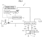
- FIG. 1 shows main elements of a hydraulic excavator 1, which is a work machine according to the present embodiment.
- the main elements include a controller 2, an engine 3, a hydraulic pump 4, a hydraulic cylinder 5, a control valve 6, an operation unit 7, and a work arm 11 and a bucket 8 which are shown in FIG. 2 .
- the engine 3 drives the hydraulic pump 4.
- the hydraulic pump 4 constitutes a pump unit, configured to be driven by the engine 3 to thereby discharge hydraulic fluid.
- the hydraulic pump 4 is a variable displacement hydraulic pump having a variable pump capacity. As will be described later, the pump capacity of the hydraulic pump 4 is controlled by the controller 2.
- the hydraulic fluid discharged from the hydraulic pump 4 is supplied to the hydraulic cylinder 5 through the control valve 6.
- the hydraulic cylinder 5 is a hydraulic actuator to be driven by hydraulic fluid supplied from the hydraulic pump 4, being a bucket cylinder in the present embodiment, which is driven by the hydraulic fluid to perform expansion and contraction motions to make the bucket 8 perform a work motion.
- the hydraulic cylinder 5 includes a piston 55, which partitions the inside of the hydraulic cylinder 5 into a head-side chamber 51 and a rod-side chamber 53.
- the hydraulic cylinder 5 has a first port 51a and a second port 53a, each of which is a supply/discharge port for hydraulic fluid, the head-side chamber 51 communicating with the first port 51a, and the rod-side chamber 53 communicating with the second port 53a.
- the hydraulic cylinder 5 is configured to made perform an expansion motion, which is a motion in an expansion direction, by the supply of hydraulic fluid to the head-side chamber 51 through the first port 51a, with discharge of hydraulic fluid from the rod-side chamber 53 through the second port 53a.
- the hydraulic cylinder 5 is configured to made perform a contraction motion, which is a motion in a contraction direction, by the supply of hydraulic fluid to the rod-side chamber 53 through the second port 53a, with discharge of hydraulic fluid from the head-side chamber 51 through the first port 51a.
- the bucket 8 is a work device, attached to a tip part of the work arm 11 to be moved by the work arm 11.
- the work arm 11 includes a boom attached to the machine body of the hydraulic excavator 1 capably of rising and falling, and an arm connected to the distal end of the boom capably of rotational movement, the bucket 8 attached to the distal end of the arm.
- the bucket 8 is rotationally moved with respect to the work arm 11 by the expansion and contraction motions of the hydraulic cylinder 5, thereby performing a work motion.
- the work motion in the present embodiment, includes an excavation motion and an earth removal motion.
- the control valve 6 is a direction selector valve that switches a direction in which the hydraulic fluid discharged from the hydraulic pump 4 flows into the hydraulic cylinder 5.
- the control valve 6 according to the present embodiment is a pilot-operated hydraulic selector valve having a head-side pilot port and a rod-side pilot port.
- the control valve 6 is opened by the supply of pilot pressure to the head-side pilot port so as to allow hydraulic fluid to be supplied to the head-side chamber 51 of the hydraulic cylinder 5 through a fluid passage 61 and the first port 51a.
- the control valve 6 is opened by the supply of pilot pressure to the rod-side pilot port so as to allow hydraulic fluid to be supplied to the rod-side chamber 53 of the hydraulic cylinder 5 through the second port 53a and the fluid passage 63.
- the control valve 6 is a flow regulating valve having a variable opening degree. Specifically, the opening degree of the control valve 6 is changed so as to allow hydraulic fluid to flow at a flow rate that is increased with an increase in the pilot pressure that is input to the control valve 6.
- the regulation of the flow rate by the control valve 6 allows respective speeds of the expansion and contraction motions of the hydraulic cylinder 5 and the work motion (rotational movement) of the bucket 8 associated with the expansion and contraction motions to be controlled.
- the operation unit 7 allows a work operation to be applied to the operation unit 7.
- the work operation is an operation to be applied to the operation unit 7 for making the control valve 6 perform an action to make the hydraulic cylinder 5 perform the expansion and contraction motions to make the bucket 8 perform the work motion.
- the operation unit 7 according to the present embodiment includes an operation lever 7a and a pilot valve 7b.
- the operation lever 7a allows the work operation to be applied to the operation lever 7a to rotationally move the operation lever 7a in the direction of the work operation.
- the pilot valve 7b is connected to each of the head-side pilot port and the rod-side pilot port of the control valve 6 through a pilot line 71.
- the pilot valve 7b is opened in conjunction with the operation lever 7a, allowing pilot pressure to be input to the control valve 6 through the pilot line 71 and changing the pilot pressure in accordance with the magnitude of the work operation applied to the operation lever 7a, namely, an operation amount.
- the controller 2 is connected with an engine speed setting device 31 for setting the rotation speed of the engine 3.
- the controller 2 controls the drive of the engine 3 so as to make the engine 3 rotate at the rotation speed set by the engine speed setting device 31.
- the fluid passage 61 is provided with a head-pressure sensor 61S, and the fluid passage 63 is provided with a rod-pressure sensor 63S.
- the head-pressure sensor 61S detects a head pressure, which is the pressure of the hydraulic fluid supplied from the control valve 6 to the head-side chamber 51 through the fluid passage 61, being substantially equal to the pressure in the head-side chamber 51.
- the rod-pressure sensor 63S detects a rod pressure, which is the pressure of the hydraulic fluid supplied to the rod-side chamber 53, being substantially equal to the pressure in the rod-side chamber 53.
- Each of the head-pressure sensor 61S and the rod-pressure sensor 63S is a cylinder pressure detection sensor that detects a cylinder pressure, which is the working pressure of the hydraulic cylinder 5.
- the head-pressure sensor 61S and the rod-pressure sensor 63S are connected to the controller 2.
- the head-pressure sensor 61S inputs an electric signal corresponding to the head pressure, namely, a head pressure detection signal, to the controller 2.
- the rod-pressure sensor 63S inputs an electric signal corresponding to the rod pressure, namely, a rod pressure detection signal, to the controller 2.
- the pilot line 71 is provided with a pilot pressure sensor 7S.
- the pilot pressure sensor 7S detects a pilot pressure to be input from the operation unit 7 to the control valve 6 through the pilot line 71. Since the pilot pressure corresponds to the operation amount of the work operation, the pilot pressure sensor 7S serves as an operation detector that detects the work operation.
- the pilot pressure sensor 7S is connected to the controller 2 to input an electric signal corresponding to the pilot pressure, namely, an operation detection signal, which is an electric signal corresponding to the operation amount, to the controller 2.
- the operation detector that detects the work operation alternatively, may be an angle sensor that detects the tilt angle of the operation lever 7a.
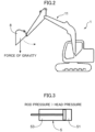
- the earth removal posture is a posture in which the bucket 8 having been raised to a suitable height by the work arm 11 as shown in FIG. 2 is opened downward to allow the earth and sand in the bucket 8 to fall, and the excavation motion is a motion of the bucket 8 to excavate the ground surface to scoop the earth and sand.
- the controller 2 judges whether or not the work operation applied to the operation unit 7 corresponds to a low-pressure operation, and performs control to increase the pump capacity when judging the work operation to be the low-pressure operation.
- the low-pressure operation is an operation for making the control valve 6 perform an action for allowing hydraulic fluid to be supplied to the low-pressure side of the hydraulic cylinder 5, namely, the head-side chamber 51 when the hydraulic cylinder 5 performs the expansion motion.
- the control for the excavation motion in consideration of the low-pressure operation with reference to the flowchart of FIG. 10 .
- the controller 2 compares the head pressure detected by the head-pressure sensor 61S with the rod pressure detected by the rod-pressure sensor 63S (step S11). Only when judging that the head pressure is lower than the rod pressure (YES in step S11), that is, only when judging that the head-side chamber 51 is the low-pressure side of the hydraulic cylinder 5, the controller 2 estimates the bucket 8 to be in the earth removal posture of being opened downward (step S12) and performs the following processing based on the estimation.
- the controller 2 judges whether or not a low-pressure operation is applied to the operation unit 7, based on the pilot pressure detected by the pilot pressure sensor 7S (step S12).
- the low-pressure operation is a work operation for making the control valve 6 perform an action to allow hydraulic fluid discharged from the hydraulic pump 4 to be supplied to the low-pressure side of the hydraulic cylinder 5, namely, the head-side chamber 51, that is, an operation for moving the bucket 8 in the earth removal posture, in the embracement direction.
- step S13 When judging that the low-pressure operation, which is an operation for allowing hydraulic fluid to be supplied to the head-side chamber 51 as the low-pressure side of the hydraulic cylinder 5, is applied to the operation unit 7 (YES in step S13), the controller 2 executes the following pump capacity control (steps S14 to S16).
- step S14 the controller 2 judges whether or not the engine speed is higher than a predetermined rotation speed.
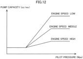
- the controller 2 sets the pump capacity of the hydraulic pump 4 according to the pilot pressure, that is, according to the operation amount (step S15). Specifically, the controller 2 stores the relationship between the pilot pressure and the pump capacity as shown in FIG. 12 , the relationship varied depending on the engine speed, and determines the pump capacity based on the relationship and the pilot pressure.
- step S14 the controller 2 sets the pump capacity corresponding to the pilot pressure detected by the pilot pressure sensor 7S, based on the graph corresponding to the "ENGINE SPEED HIGH", which is the case where the engine speed is higher than the predetermined rotation speed, among the plurality of graphs shown in FIG. 12 (step S15).
- the controller 2 thus, executes a control to increase the pump capacity with an increase in the pilot pressure, that is, with an increase in the operation amount.
- each of a minute operation range including the minimum value of the pilot pressure and a large-operation range including the maximum value is set as a dead zone, which is a range in which the pump capacity is kept constant regardless of a variation in the pilot pressure.
- the controller 2 sets the pump capacity of the hydraulic pump 4 based on both the pilot pressure and the engine speed (step S16). Specifically, as illustrated by respective graphs of the "ENGINE SPEED HIGH” "ENGINE SPEED MIDDLE” and “ENGINE SPEED LOW” (the case where the engine speed is lower than the predetermined rotation speed) in FIG. 12 , the controller 2 makes such a determination of the pump capacity as to increase the pump capacity with an increase in the pilot pressure detected by the pilot pressure sensor 7S and as to increase the increase rate of the pump capacity to an increase in the pilot pressure, with a decrease in the engine speed.
- the controller 2 renders the increase rate of the pump capacity to an increase in the pilot pressure greater than the increase rate in the case where the engine speed is such a high rotation speed as to correspond to the graph of the "ENGINE SPEED HIGH " in FIG. 12 .
- the controller 2 renders the increase rate of the pump capacity to an increase in the pilot pressure greater than the increase rate in the case where the engine speed is in the middle level corresponding to the graph of the "ENGINE SPEED MIDDLE" in FIG. 12 .
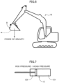
- the embracement posture is a posture in which the bucket 8 having been raised to a suitable height by the work arm 11 is opened upward to hold the earth and sand, and the earth removal motion is a motion of releasing downward the earth and sand that had been held by the bucket 8 to drop it.
- the controller 2 judges whether or not the work operation applied to the operation unit 7 corresponds to a low-pressure operation, and performs control to increase the pump capacity when judging the work operation to be the low-pressure operation.
- the low-pressure operation when the hydraulic cylinder 5 performs the expansion motion is an operation for making hydraulic fluid supplied to the rod-side chamber 53 as the low-pressure side of the hydraulic cylinder 5.
- the control for the earth removal motion in consideration of the low-pressure operation with reference to the flowchart of FIG. 11 .
- the controller 2 compares the head pressure detected by the head-pressure sensor 61S with the rod pressure detected by the rod-pressure sensor 63S (step S21). Only when judging that the rod pressure is lower than the head pressure (YES in step S21), that is, only when judging that the rod-side chamber 53 is the low-pressure side of the hydraulic cylinder 5, the controller 2 estimates the bucket 8 to be in the embracement posture of being opened upward (step S22) and performs the following processing based on the estimation.
- the controller 2 judges whether or not a low-pressure operation is applied to the operation unit 7, based on the pilot pressure detected by the pilot pressure sensor 7S (step S22).
- the low-pressure operation is a work operation for making the control valve 6 perform an action to allow hydraulic fluid discharged from the hydraulic pump 4 to be supplied to the low-pressure side of the hydraulic cylinder 5, namely, the rod-side chamber 53, that is, an operation for moving the bucket 8 in the embracement posture, in the earth removal direction.
- step S23 When judging that the low-pressure operation, which is an operation for allowing hydraulic fluid to be supplied to the head-side chamber 51 as the low-pressure side of the hydraulic cylinder 5, is applied to the operation unit 7 (YES in step S23), the controller 2 executes the pump capacity control (steps S24 to S26).
- This pump capacity control is the same as the control by the above-described processes of steps S14 to S16 in FIG. 10 .
- the controller 2 executes the control for increasing the pump capacity (step S15 or step S16 in FIG. 10 , step S25 or step S26 in FIG. 11 ).
- the control makes it possible to reliably prevent negative pressure (cavitation) from occurring in the circuit for supplying hydraulic fluid to the hydraulic cylinder 5 with no use of any makeup line.
- the controller 2 which quantitatively estimates the posture of the bucket 8 (earth removal posture or embracement posture) based on the comparison between the head pressure detected by the head-pressure sensor 61S and the rod pressure detected by the rod-pressure sensor 63S, can make more accurate judgement on whether or not an operation that induces the cavitation (low-pressure operation) is applied to the operation unit 7, based on the thus estimated posture.
- the controller 2 which increases the increase rate of the pump capacity to an increase in the operation amount, with a decrease in the engine speed (see FIG. 12 ), that is, performs the control to increase the increase rate of the pump capacity to the operation amount, with a decrease in the engine speed, can reliably prevent cavitation even when the engine speed is significantly reduced.
- the above-described control performed by the controller 2 allows the pump capacity to be greatly increased with a decrease in the engine speed only when the engine speed is lower than the predetermined rotation speed, that is, only with a possibility of insufficiency of the pump discharge amount. This prevents, conversely, the pump capacity from being significantly increased despite that the engine speed is higher than the threshold to allow the discharge amount of the hydraulic fluid to be sufficient.
- the pump unit that supplies hydraulic fluid to the hydraulic cylinder 5 in the above embodiment is composed of the single hydraulic pump 4, the pump unit according to the present invention may be constituted by a plurality of hydraulic pumps including at least one variable displacement hydraulic pump. In short, hydraulic fluid may be supplied from the plurality of hydraulic pumps to the hydraulic cylinder 5.
- FIG. 13 shows a hydraulic excavator 101 according to a modification example.
- the hydraulic excavator 101 includes a pump unit including two hydraulic pumps 41 and 42 in place of a single hydraulic pump 4 shown in FIG. 1 , and each of the hydraulic pumps 41 and 42 is composed of a variable displacement hydraulic pump.
- the hydraulic excavator 101 further includes a merging valve 9, which allows the hydraulic fluid discharged from the hydraulic pump 41 and the hydraulic fluid discharged from the hydraulic pump 42 to be merged with each other and supplied to the hydraulic cylinder 5.
- the hydraulic excavator 101 includes a controller 2 in the same manner as the hydraulic excavator 1 according to the embodiment, and the controller 2 is configured to increase the pump capacity of at least one of the hydraulic pumps 41, 42 when judging that the low-pressure operation is applied to the operation unit 7, similarly to step S13 of FIG. 10 or step S23 of FIG. 11 described above.
- the posture detector is not limited to the embodiment.
- the posture detector may include, for example, a plurality of angle sensors attached to the bucket 8, and the boom and the arm included in the work arm 11, respectively. Respective angles detected by the plurality of angle sensors allow the posture of the bucket 8 (for example, the earth removal posture or the embracement posture) to be estimated therefrom.
- control according to the embodiment changes the increase rate of the pump capacity to the operation amount in accordance with the engine speed
- control performed by the controller according to the present invention is not limited thereto.
- the controller according to the present invention may be configured to increase the pump capacity by a certain amount regardless of the engine speed when judging that the low-pressure operation has been applied to the operation unit.
- a work machine including a hydraulic pump, the work machine being capable of effectively preventing cavitation.
- the work machine includes a work device, a pump unit, a hydraulic actuator, a posture detector, a control valve, an operation unit, and a controller.
- the pump unit includes a variable displacement hydraulic pump having a variable pump capacity.
- the hydraulic actuator is driven by hydraulic fluid supplied from the pump unit to actuate the work device.
- the posture detector acquires posture information that is information about a posture of the work device.
- the control valve is disposed between the pump unit and the hydraulic actuator and performs an action to change supply of hydraulic fluid from the pump unit to the hydraulic actuator.
- the operation unit allows a work operation for making the control valve perform the action to be applied to the operation unit.
- the operation detector detects the work operation applied to the operation unit.
- the controller judges whether or not the work operation detected by the operation detector is a low-pressure operation based on the posture information acquired by the posture detector, and increases the pump capacity of the variable displacement hydraulic pump when judging that the work operation is the low-pressure operation.
- the low-pressure operation is an operation for making the control valve perform an action of allowing hydraulic fluid to be supplied from the pump unit to a low-pressure side of the hydraulic actuator.
- the controller which judges whether or not the work operation detected by the operation detector is the low-pressure operation, based on the posture information acquired by the posture detector, and increases the pump capacity when judging that the work operation is the low-pressure operation, can reliably prevent cavitation in the hydraulic actuator.
- the hydraulic actuator has a first port and a second port through each of which hydraulic fluid can flow into and discharge from the hydraulic actuator, and the hydraulic actuator is configured to be made perform a motion in a first direction by supply of hydraulic fluid to the first port with discharge of hydraulic fluid through the second port and configured to be made perform a motion in a second direction by supply of hydraulic fluid to the second port, with discharge of hydraulic fluid through the first port
- the low-pressure operation is an operation for making the control valve perform an action of allowing hydraulic fluid to be supplied to a port having a lower pressure selected from the first port and the second port.
- the hydraulic actuator may be, for example, a hydraulic cylinder.
- the hydraulic cylinder has a head-side chamber communicating with the first port and a rod-side chamber communicating with the second port, configured to be made perform the action in an expansion direction by supply of hydraulic fluid to the head-side chamber through the first port, with discharge of hydraulic fluid from the rod-side chamber through the second port, and configured to be made perform the action in a contraction direction by supply of hydraulic fluid to the rod-side chamber through the second port, with discharge of hydraulic fluid from the head-side chamber through the first port.
- the posture detector is configured to detect each of a head pressure, which is a pressure of the head-side chamber of the hydraulic cylinder, and a rod pressure, which is a pressure of the rod-side chamber of the hydraulic cylinder, and the controller is configured to judge the operation for allowing the control valve to perform an action for allowing hydraulic fluid to be supplied to a hydraulic chamber having a lower pressure selected from the head-side chamber and the rod-side chamber to be the low-pressure operation.
- the low-pressure operation can also be defined as an operation for moving the work device in the same direction as a direction in which the force of gravity acting on the work device moves the work device when the work device is in the posture detected by the posture detector.
- the controller is configured to increase the pump capacity at a degree that increases with a decrease in a rotation speed of the engine when judging that the work operation is the low-pressure operation.
- the controller is configured to increase the pump capacity at the greatest degree when judging that the operation is the low-pressure operation in a case where the rotation speed of the engine is equal to or less than a predetermined rotation speed.
Landscapes
- Engineering & Computer Science (AREA)
- General Engineering & Computer Science (AREA)
- Physics & Mathematics (AREA)
- Fluid Mechanics (AREA)
- Mining & Mineral Resources (AREA)
- Civil Engineering (AREA)
- Structural Engineering (AREA)
- Mechanical Engineering (AREA)
- Chemical & Material Sciences (AREA)
- Analytical Chemistry (AREA)
- Operation Control Of Excavators (AREA)
Applications Claiming Priority (2)
| Application Number | Priority Date | Filing Date | Title |
|---|---|---|---|
| JP2021193728A JP7815713B2 (ja) | 2021-11-30 | 2021-11-30 | 作業機械 |
| PCT/JP2022/040202 WO2023100558A1 (ja) | 2021-11-30 | 2022-10-27 | 作業機械 |
Publications (2)
| Publication Number | Publication Date |
|---|---|
| EP4411079A1 true EP4411079A1 (de) | 2024-08-07 |
| EP4411079A4 EP4411079A4 (de) | 2025-02-12 |
Family
ID=86611868
Family Applications (1)
| Application Number | Title | Priority Date | Filing Date |
|---|---|---|---|
| EP22900991.5A Pending EP4411079A4 (de) | 2021-11-30 | 2022-10-27 | Arbeitsmaschine |
Country Status (5)
| Country | Link |
|---|---|
| US (1) | US12509858B2 (de) |
| EP (1) | EP4411079A4 (de) |
| JP (1) | JP7815713B2 (de) |
| CN (1) | CN118265830A (de) |
| WO (1) | WO2023100558A1 (de) |
Family Cites Families (12)
| Publication number | Priority date | Publication date | Assignee | Title |
|---|---|---|---|---|
| JPH01260125A (ja) * | 1988-04-07 | 1989-10-17 | Yutani Heavy Ind Ltd | 油圧ショベルの油圧回路 |
| JP2005344482A (ja) * | 2004-06-07 | 2005-12-15 | Hitachi Constr Mach Co Ltd | 地表処理作業、土木工事及び地雷除去作業の管理支援システム |
| GB0614534D0 (en) * | 2006-07-21 | 2006-08-30 | Artemis Intelligent Power Ltd | Fluid power distribution and control system |
| JP2011075045A (ja) * | 2009-09-30 | 2011-04-14 | Hitachi Constr Mach Co Ltd | 油圧作業機械の油圧制御装置 |
| JP6373728B2 (ja) * | 2014-11-10 | 2018-08-15 | 日立建機株式会社 | 建設機械 |
| JP6474718B2 (ja) * | 2015-12-25 | 2019-02-27 | 日立建機株式会社 | 建設機械の油圧制御装置 |
| WO2018020689A1 (ja) * | 2016-07-29 | 2018-02-01 | 株式会社小松製作所 | 制御システム、作業機械及び制御方法 |
| JP7302986B2 (ja) * | 2019-02-28 | 2023-07-04 | 日立建機株式会社 | 建設機械 |
| JP7276056B2 (ja) * | 2019-09-30 | 2023-05-18 | コベルコ建機株式会社 | 作業機械 |
| JP7400552B2 (ja) | 2020-03-06 | 2023-12-19 | コベルコ建機株式会社 | 作業機械の油圧駆動装置 |
| CN111733919A (zh) | 2020-06-29 | 2020-10-02 | 潍柴动力股份有限公司 | 挖掘机液压系统的防吸空控制方法、控制装置和挖掘机 |
| JP7080947B2 (ja) * | 2020-09-30 | 2022-06-06 | 住友建機株式会社 | ショベル |
-
2021
- 2021-11-30 JP JP2021193728A patent/JP7815713B2/ja active Active
-
2022
- 2022-10-27 EP EP22900991.5A patent/EP4411079A4/de active Pending
- 2022-10-27 WO PCT/JP2022/040202 patent/WO2023100558A1/ja not_active Ceased
- 2022-10-27 CN CN202280076976.XA patent/CN118265830A/zh active Pending
- 2022-10-27 US US18/708,415 patent/US12509858B2/en active Active
Also Published As
| Publication number | Publication date |
|---|---|
| WO2023100558A1 (ja) | 2023-06-08 |
| CN118265830A (zh) | 2024-06-28 |
| US20250012051A1 (en) | 2025-01-09 |
| JP7815713B2 (ja) | 2026-02-18 |
| US12509858B2 (en) | 2025-12-30 |
| JP2023080403A (ja) | 2023-06-09 |
| EP4411079A4 (de) | 2025-02-12 |
Similar Documents
| Publication | Publication Date | Title |
|---|---|---|
| EP3301229B1 (de) | Hydraulische antriebsvorrichtung für eine arbeitsmaschine | |
| US10914328B2 (en) | Work machine | |
| KR20090070802A (ko) | 건설장비의 전자유압 시스템 | |
| JP6934454B2 (ja) | 建設機械 | |
| CN112105785A (zh) | 工程机械的液压驱动装置 | |
| US11454002B2 (en) | Hydraulic drive system for work machine | |
| JPWO2016111205A1 (ja) | 建設機械 | |
| EP1447480B1 (de) | Baumaschine | |
| JP2017223096A (ja) | ショベル | |
| JP7085996B2 (ja) | 作業機械および作業機械の制御方法 | |
| KR20240038796A (ko) | 작업 기계 | |
| EP3725959B1 (de) | Bagger | |
| US11970840B2 (en) | Work machine | |
| CN110352303B (zh) | 工程机械的驱动装置 | |
| JP6615137B2 (ja) | 建設機械の油圧駆動装置 | |
| JP6091154B2 (ja) | 油圧駆動システム | |
| EP4411079A1 (de) | Arbeitsmaschine | |
| JP6782852B2 (ja) | 建設機械 | |
| JP2020143446A (ja) | 建設機械 | |
| CN114423907B (zh) | 工程机械 | |
| JP7119686B2 (ja) | 旋回式油圧作業機械 | |
| JP6943798B2 (ja) | ショベル | |
| JP3643300B2 (ja) | 油圧作業機械 | |
| JP6964059B2 (ja) | 建設機械 | |
| EP4640956A1 (de) | Regenerationssteuerungsvorrichtung für eine arbeitsmaschine |
Legal Events
| Date | Code | Title | Description |
|---|---|---|---|
| STAA | Information on the status of an ep patent application or granted ep patent |
Free format text: STATUS: THE INTERNATIONAL PUBLICATION HAS BEEN MADE |
|
| PUAI | Public reference made under article 153(3) epc to a published international application that has entered the european phase |
Free format text: ORIGINAL CODE: 0009012 |
|
| STAA | Information on the status of an ep patent application or granted ep patent |
Free format text: STATUS: REQUEST FOR EXAMINATION WAS MADE |
|
| 17P | Request for examination filed |
Effective date: 20240502 |
|
| AK | Designated contracting states |
Kind code of ref document: A1 Designated state(s): AL AT BE BG CH CY CZ DE DK EE ES FI FR GB GR HR HU IE IS IT LI LT LU LV MC ME MK MT NL NO PL PT RO RS SE SI SK SM TR |
|
| A4 | Supplementary search report drawn up and despatched |
Effective date: 20250114 |
|
| RIC1 | Information provided on ipc code assigned before grant |
Ipc: F15B 21/047 20190101ALI20250108BHEP Ipc: F15B 21/00 20060101ALI20250108BHEP Ipc: E02F 9/22 20060101AFI20250108BHEP |
|
| DAV | Request for validation of the european patent (deleted) | ||
| DAX | Request for extension of the european patent (deleted) |