WO2018020689A1 - 制御システム、作業機械及び制御方法 - Google Patents
制御システム、作業機械及び制御方法 Download PDFInfo
- Publication number
- WO2018020689A1 WO2018020689A1 PCT/JP2016/072447 JP2016072447W WO2018020689A1 WO 2018020689 A1 WO2018020689 A1 WO 2018020689A1 JP 2016072447 W JP2016072447 W JP 2016072447W WO 2018020689 A1 WO2018020689 A1 WO 2018020689A1
- Authority
- WO
- WIPO (PCT)
- Prior art keywords
- hydraulic
- flow rate
- hydraulic pump
- state
- pressure
- Prior art date
Links
Images


Classifications
-
- E—FIXED CONSTRUCTIONS
- E02—HYDRAULIC ENGINEERING; FOUNDATIONS; SOIL SHIFTING
- E02F—DREDGING; SOIL-SHIFTING
- E02F9/00—Component parts of dredgers or soil-shifting machines, not restricted to one of the kinds covered by groups E02F3/00 - E02F7/00
- E02F9/20—Drives; Control devices
- E02F9/22—Hydraulic or pneumatic drives
- E02F9/2221—Control of flow rate; Load sensing arrangements
-
- F—MECHANICAL ENGINEERING; LIGHTING; HEATING; WEAPONS; BLASTING
- F15—FLUID-PRESSURE ACTUATORS; HYDRAULICS OR PNEUMATICS IN GENERAL
- F15B—SYSTEMS ACTING BY MEANS OF FLUIDS IN GENERAL; FLUID-PRESSURE ACTUATORS, e.g. SERVOMOTORS; DETAILS OF FLUID-PRESSURE SYSTEMS, NOT OTHERWISE PROVIDED FOR
- F15B13/00—Details of servomotor systems ; Valves for servomotor systems
- F15B13/02—Fluid distribution or supply devices characterised by their adaptation to the control of servomotors
- F15B13/06—Fluid distribution or supply devices characterised by their adaptation to the control of servomotors for use with two or more servomotors
-
- E—FIXED CONSTRUCTIONS
- E02—HYDRAULIC ENGINEERING; FOUNDATIONS; SOIL SHIFTING
- E02F—DREDGING; SOIL-SHIFTING
- E02F3/00—Dredgers; Soil-shifting machines
- E02F3/04—Dredgers; Soil-shifting machines mechanically-driven
- E02F3/28—Dredgers; Soil-shifting machines mechanically-driven with digging tools mounted on a dipper- or bucket-arm, i.e. there is either one arm or a pair of arms, e.g. dippers, buckets
- E02F3/34—Dredgers; Soil-shifting machines mechanically-driven with digging tools mounted on a dipper- or bucket-arm, i.e. there is either one arm or a pair of arms, e.g. dippers, buckets with bucket-arms, i.e. a pair of arms, e.g. manufacturing processes, form, geometry, material of bucket-arms directly pivoted on the frames of tractors or self-propelled machines
-
- E—FIXED CONSTRUCTIONS
- E02—HYDRAULIC ENGINEERING; FOUNDATIONS; SOIL SHIFTING
- E02F—DREDGING; SOIL-SHIFTING
- E02F3/00—Dredgers; Soil-shifting machines
- E02F3/04—Dredgers; Soil-shifting machines mechanically-driven
- E02F3/28—Dredgers; Soil-shifting machines mechanically-driven with digging tools mounted on a dipper- or bucket-arm, i.e. there is either one arm or a pair of arms, e.g. dippers, buckets
- E02F3/36—Component parts
- E02F3/42—Drives for dippers, buckets, dipper-arms or bucket-arms
- E02F3/422—Drive systems for bucket-arms, front-end loaders, dumpers or the like
-
- E—FIXED CONSTRUCTIONS
- E02—HYDRAULIC ENGINEERING; FOUNDATIONS; SOIL SHIFTING
- E02F—DREDGING; SOIL-SHIFTING
- E02F9/00—Component parts of dredgers or soil-shifting machines, not restricted to one of the kinds covered by groups E02F3/00 - E02F7/00
- E02F9/08—Superstructures; Supports for superstructures
- E02F9/10—Supports for movable superstructures mounted on travelling or walking gears or on other superstructures
- E02F9/12—Slewing or traversing gears
- E02F9/121—Turntables, i.e. structure rotatable about 360°
-
- E—FIXED CONSTRUCTIONS
- E02—HYDRAULIC ENGINEERING; FOUNDATIONS; SOIL SHIFTING
- E02F—DREDGING; SOIL-SHIFTING
- E02F9/00—Component parts of dredgers or soil-shifting machines, not restricted to one of the kinds covered by groups E02F3/00 - E02F7/00
- E02F9/20—Drives; Control devices
- E02F9/22—Hydraulic or pneumatic drives
- E02F9/2221—Control of flow rate; Load sensing arrangements
- E02F9/2239—Control of flow rate; Load sensing arrangements using two or more pumps with cross-assistance
- E02F9/2242—Control of flow rate; Load sensing arrangements using two or more pumps with cross-assistance including an electronic controller
-
- E—FIXED CONSTRUCTIONS
- E02—HYDRAULIC ENGINEERING; FOUNDATIONS; SOIL SHIFTING
- E02F—DREDGING; SOIL-SHIFTING
- E02F9/00—Component parts of dredgers or soil-shifting machines, not restricted to one of the kinds covered by groups E02F3/00 - E02F7/00
- E02F9/20—Drives; Control devices
- E02F9/22—Hydraulic or pneumatic drives
- E02F9/2264—Arrangements or adaptations of elements for hydraulic drives
- E02F9/2267—Valves or distributors
-
- E—FIXED CONSTRUCTIONS
- E02—HYDRAULIC ENGINEERING; FOUNDATIONS; SOIL SHIFTING
- E02F—DREDGING; SOIL-SHIFTING
- E02F9/00—Component parts of dredgers or soil-shifting machines, not restricted to one of the kinds covered by groups E02F3/00 - E02F7/00
- E02F9/20—Drives; Control devices
- E02F9/22—Hydraulic or pneumatic drives
- E02F9/2264—Arrangements or adaptations of elements for hydraulic drives
- E02F9/2271—Actuators and supports therefor and protection therefor
-
- E—FIXED CONSTRUCTIONS
- E02—HYDRAULIC ENGINEERING; FOUNDATIONS; SOIL SHIFTING
- E02F—DREDGING; SOIL-SHIFTING
- E02F9/00—Component parts of dredgers or soil-shifting machines, not restricted to one of the kinds covered by groups E02F3/00 - E02F7/00
- E02F9/20—Drives; Control devices
- E02F9/22—Hydraulic or pneumatic drives
- E02F9/2278—Hydraulic circuits
- E02F9/2292—Systems with two or more pumps
-
- E—FIXED CONSTRUCTIONS
- E02—HYDRAULIC ENGINEERING; FOUNDATIONS; SOIL SHIFTING
- E02F—DREDGING; SOIL-SHIFTING
- E02F9/00—Component parts of dredgers or soil-shifting machines, not restricted to one of the kinds covered by groups E02F3/00 - E02F7/00
- E02F9/20—Drives; Control devices
- E02F9/22—Hydraulic or pneumatic drives
- E02F9/2278—Hydraulic circuits
- E02F9/2296—Systems with a variable displacement pump
-
- F—MECHANICAL ENGINEERING; LIGHTING; HEATING; WEAPONS; BLASTING
- F15—FLUID-PRESSURE ACTUATORS; HYDRAULICS OR PNEUMATICS IN GENERAL
- F15B—SYSTEMS ACTING BY MEANS OF FLUIDS IN GENERAL; FLUID-PRESSURE ACTUATORS, e.g. SERVOMOTORS; DETAILS OF FLUID-PRESSURE SYSTEMS, NOT OTHERWISE PROVIDED FOR
- F15B11/00—Servomotor systems without provision for follow-up action; Circuits therefor
- F15B11/02—Systems essentially incorporating special features for controlling the speed or actuating force of an output member
- F15B11/04—Systems essentially incorporating special features for controlling the speed or actuating force of an output member for controlling the speed
- F15B11/05—Systems essentially incorporating special features for controlling the speed or actuating force of an output member for controlling the speed specially adapted to maintain constant speed, e.g. pressure-compensated, load-responsive
- F15B11/055—Systems essentially incorporating special features for controlling the speed or actuating force of an output member for controlling the speed specially adapted to maintain constant speed, e.g. pressure-compensated, load-responsive by adjusting the pump output or bypass
-
- F—MECHANICAL ENGINEERING; LIGHTING; HEATING; WEAPONS; BLASTING
- F15—FLUID-PRESSURE ACTUATORS; HYDRAULICS OR PNEUMATICS IN GENERAL
- F15B—SYSTEMS ACTING BY MEANS OF FLUIDS IN GENERAL; FLUID-PRESSURE ACTUATORS, e.g. SERVOMOTORS; DETAILS OF FLUID-PRESSURE SYSTEMS, NOT OTHERWISE PROVIDED FOR
- F15B11/00—Servomotor systems without provision for follow-up action; Circuits therefor
- F15B11/16—Servomotor systems without provision for follow-up action; Circuits therefor with two or more servomotors
- F15B11/161—Servomotor systems without provision for follow-up action; Circuits therefor with two or more servomotors with sensing of servomotor demand or load
- F15B11/162—Servomotor systems without provision for follow-up action; Circuits therefor with two or more servomotors with sensing of servomotor demand or load for giving priority to particular servomotors or users
-
- F—MECHANICAL ENGINEERING; LIGHTING; HEATING; WEAPONS; BLASTING
- F15—FLUID-PRESSURE ACTUATORS; HYDRAULICS OR PNEUMATICS IN GENERAL
- F15B—SYSTEMS ACTING BY MEANS OF FLUIDS IN GENERAL; FLUID-PRESSURE ACTUATORS, e.g. SERVOMOTORS; DETAILS OF FLUID-PRESSURE SYSTEMS, NOT OTHERWISE PROVIDED FOR
- F15B11/00—Servomotor systems without provision for follow-up action; Circuits therefor
- F15B11/16—Servomotor systems without provision for follow-up action; Circuits therefor with two or more servomotors
- F15B11/17—Servomotor systems without provision for follow-up action; Circuits therefor with two or more servomotors using two or more pumps
-
- F—MECHANICAL ENGINEERING; LIGHTING; HEATING; WEAPONS; BLASTING
- F15—FLUID-PRESSURE ACTUATORS; HYDRAULICS OR PNEUMATICS IN GENERAL
- F15B—SYSTEMS ACTING BY MEANS OF FLUIDS IN GENERAL; FLUID-PRESSURE ACTUATORS, e.g. SERVOMOTORS; DETAILS OF FLUID-PRESSURE SYSTEMS, NOT OTHERWISE PROVIDED FOR
- F15B2211/00—Circuits for servomotor systems
- F15B2211/20—Fluid pressure source, e.g. accumulator or variable axial piston pump
- F15B2211/205—Systems with pumps
- F15B2211/20507—Type of prime mover
- F15B2211/20515—Electric motor
-
- F—MECHANICAL ENGINEERING; LIGHTING; HEATING; WEAPONS; BLASTING
- F15—FLUID-PRESSURE ACTUATORS; HYDRAULICS OR PNEUMATICS IN GENERAL
- F15B—SYSTEMS ACTING BY MEANS OF FLUIDS IN GENERAL; FLUID-PRESSURE ACTUATORS, e.g. SERVOMOTORS; DETAILS OF FLUID-PRESSURE SYSTEMS, NOT OTHERWISE PROVIDED FOR
- F15B2211/00—Circuits for servomotor systems
- F15B2211/20—Fluid pressure source, e.g. accumulator or variable axial piston pump
- F15B2211/205—Systems with pumps
- F15B2211/20507—Type of prime mover
- F15B2211/20523—Internal combustion engine
-
- F—MECHANICAL ENGINEERING; LIGHTING; HEATING; WEAPONS; BLASTING
- F15—FLUID-PRESSURE ACTUATORS; HYDRAULICS OR PNEUMATICS IN GENERAL
- F15B—SYSTEMS ACTING BY MEANS OF FLUIDS IN GENERAL; FLUID-PRESSURE ACTUATORS, e.g. SERVOMOTORS; DETAILS OF FLUID-PRESSURE SYSTEMS, NOT OTHERWISE PROVIDED FOR
- F15B2211/00—Circuits for servomotor systems
- F15B2211/20—Fluid pressure source, e.g. accumulator or variable axial piston pump
- F15B2211/205—Systems with pumps
- F15B2211/2053—Type of pump
- F15B2211/20546—Type of pump variable capacity
-
- F—MECHANICAL ENGINEERING; LIGHTING; HEATING; WEAPONS; BLASTING
- F15—FLUID-PRESSURE ACTUATORS; HYDRAULICS OR PNEUMATICS IN GENERAL
- F15B—SYSTEMS ACTING BY MEANS OF FLUIDS IN GENERAL; FLUID-PRESSURE ACTUATORS, e.g. SERVOMOTORS; DETAILS OF FLUID-PRESSURE SYSTEMS, NOT OTHERWISE PROVIDED FOR
- F15B2211/00—Circuits for servomotor systems
- F15B2211/20—Fluid pressure source, e.g. accumulator or variable axial piston pump
- F15B2211/205—Systems with pumps
- F15B2211/20576—Systems with pumps with multiple pumps
-
- F—MECHANICAL ENGINEERING; LIGHTING; HEATING; WEAPONS; BLASTING
- F15—FLUID-PRESSURE ACTUATORS; HYDRAULICS OR PNEUMATICS IN GENERAL
- F15B—SYSTEMS ACTING BY MEANS OF FLUIDS IN GENERAL; FLUID-PRESSURE ACTUATORS, e.g. SERVOMOTORS; DETAILS OF FLUID-PRESSURE SYSTEMS, NOT OTHERWISE PROVIDED FOR
- F15B2211/00—Circuits for servomotor systems
- F15B2211/20—Fluid pressure source, e.g. accumulator or variable axial piston pump
- F15B2211/275—Control of the prime mover, e.g. hydraulic control
-
- F—MECHANICAL ENGINEERING; LIGHTING; HEATING; WEAPONS; BLASTING
- F15—FLUID-PRESSURE ACTUATORS; HYDRAULICS OR PNEUMATICS IN GENERAL
- F15B—SYSTEMS ACTING BY MEANS OF FLUIDS IN GENERAL; FLUID-PRESSURE ACTUATORS, e.g. SERVOMOTORS; DETAILS OF FLUID-PRESSURE SYSTEMS, NOT OTHERWISE PROVIDED FOR
- F15B2211/00—Circuits for servomotor systems
- F15B2211/30—Directional control
- F15B2211/305—Directional control characterised by the type of valves
- F15B2211/30525—Directional control valves, e.g. 4/3-directional control valve
- F15B2211/3053—In combination with a pressure compensating valve
- F15B2211/3054—In combination with a pressure compensating valve the pressure compensating valve is arranged between directional control valve and output member
-
- F—MECHANICAL ENGINEERING; LIGHTING; HEATING; WEAPONS; BLASTING
- F15—FLUID-PRESSURE ACTUATORS; HYDRAULICS OR PNEUMATICS IN GENERAL
- F15B—SYSTEMS ACTING BY MEANS OF FLUIDS IN GENERAL; FLUID-PRESSURE ACTUATORS, e.g. SERVOMOTORS; DETAILS OF FLUID-PRESSURE SYSTEMS, NOT OTHERWISE PROVIDED FOR
- F15B2211/00—Circuits for servomotor systems
- F15B2211/30—Directional control
- F15B2211/305—Directional control characterised by the type of valves
- F15B2211/3056—Assemblies of multiple valves
- F15B2211/3059—Assemblies of multiple valves having multiple valves for multiple output members
- F15B2211/30595—Assemblies of multiple valves having multiple valves for multiple output members with additional valves between the groups of valves for multiple output members
-
- F—MECHANICAL ENGINEERING; LIGHTING; HEATING; WEAPONS; BLASTING
- F15—FLUID-PRESSURE ACTUATORS; HYDRAULICS OR PNEUMATICS IN GENERAL
- F15B—SYSTEMS ACTING BY MEANS OF FLUIDS IN GENERAL; FLUID-PRESSURE ACTUATORS, e.g. SERVOMOTORS; DETAILS OF FLUID-PRESSURE SYSTEMS, NOT OTHERWISE PROVIDED FOR
- F15B2211/00—Circuits for servomotor systems
- F15B2211/40—Flow control
- F15B2211/405—Flow control characterised by the type of flow control means or valve
- F15B2211/40523—Flow control characterised by the type of flow control means or valve with flow dividers
- F15B2211/4053—Flow control characterised by the type of flow control means or valve with flow dividers using valves
-
- F—MECHANICAL ENGINEERING; LIGHTING; HEATING; WEAPONS; BLASTING
- F15—FLUID-PRESSURE ACTUATORS; HYDRAULICS OR PNEUMATICS IN GENERAL
- F15B—SYSTEMS ACTING BY MEANS OF FLUIDS IN GENERAL; FLUID-PRESSURE ACTUATORS, e.g. SERVOMOTORS; DETAILS OF FLUID-PRESSURE SYSTEMS, NOT OTHERWISE PROVIDED FOR
- F15B2211/00—Circuits for servomotor systems
- F15B2211/40—Flow control
- F15B2211/415—Flow control characterised by the connections of the flow control means in the circuit
- F15B2211/41509—Flow control characterised by the connections of the flow control means in the circuit being connected to a pressure source and a directional control valve
- F15B2211/41518—Flow control characterised by the connections of the flow control means in the circuit being connected to a pressure source and a directional control valve being connected to multiple pressure sources
-
- F—MECHANICAL ENGINEERING; LIGHTING; HEATING; WEAPONS; BLASTING
- F15—FLUID-PRESSURE ACTUATORS; HYDRAULICS OR PNEUMATICS IN GENERAL
- F15B—SYSTEMS ACTING BY MEANS OF FLUIDS IN GENERAL; FLUID-PRESSURE ACTUATORS, e.g. SERVOMOTORS; DETAILS OF FLUID-PRESSURE SYSTEMS, NOT OTHERWISE PROVIDED FOR
- F15B2211/00—Circuits for servomotor systems
- F15B2211/50—Pressure control
- F15B2211/505—Pressure control characterised by the type of pressure control means
- F15B2211/50554—Pressure control characterised by the type of pressure control means the pressure control means controlling a pressure downstream of the pressure control means, e.g. pressure reducing valve
-
- F—MECHANICAL ENGINEERING; LIGHTING; HEATING; WEAPONS; BLASTING
- F15—FLUID-PRESSURE ACTUATORS; HYDRAULICS OR PNEUMATICS IN GENERAL
- F15B—SYSTEMS ACTING BY MEANS OF FLUIDS IN GENERAL; FLUID-PRESSURE ACTUATORS, e.g. SERVOMOTORS; DETAILS OF FLUID-PRESSURE SYSTEMS, NOT OTHERWISE PROVIDED FOR
- F15B2211/00—Circuits for servomotor systems
- F15B2211/60—Circuit components or control therefor
- F15B2211/63—Electronic controllers
- F15B2211/6303—Electronic controllers using input signals
- F15B2211/6306—Electronic controllers using input signals representing a pressure
- F15B2211/6309—Electronic controllers using input signals representing a pressure the pressure being a pressure source supply pressure
-
- F—MECHANICAL ENGINEERING; LIGHTING; HEATING; WEAPONS; BLASTING
- F15—FLUID-PRESSURE ACTUATORS; HYDRAULICS OR PNEUMATICS IN GENERAL
- F15B—SYSTEMS ACTING BY MEANS OF FLUIDS IN GENERAL; FLUID-PRESSURE ACTUATORS, e.g. SERVOMOTORS; DETAILS OF FLUID-PRESSURE SYSTEMS, NOT OTHERWISE PROVIDED FOR
- F15B2211/00—Circuits for servomotor systems
- F15B2211/60—Circuit components or control therefor
- F15B2211/63—Electronic controllers
- F15B2211/6303—Electronic controllers using input signals
- F15B2211/6306—Electronic controllers using input signals representing a pressure
- F15B2211/6313—Electronic controllers using input signals representing a pressure the pressure being a load pressure
-
- F—MECHANICAL ENGINEERING; LIGHTING; HEATING; WEAPONS; BLASTING
- F15—FLUID-PRESSURE ACTUATORS; HYDRAULICS OR PNEUMATICS IN GENERAL
- F15B—SYSTEMS ACTING BY MEANS OF FLUIDS IN GENERAL; FLUID-PRESSURE ACTUATORS, e.g. SERVOMOTORS; DETAILS OF FLUID-PRESSURE SYSTEMS, NOT OTHERWISE PROVIDED FOR
- F15B2211/00—Circuits for servomotor systems
- F15B2211/60—Circuit components or control therefor
- F15B2211/63—Electronic controllers
- F15B2211/6303—Electronic controllers using input signals
- F15B2211/6306—Electronic controllers using input signals representing a pressure
- F15B2211/6316—Electronic controllers using input signals representing a pressure the pressure being a pilot pressure
-
- F—MECHANICAL ENGINEERING; LIGHTING; HEATING; WEAPONS; BLASTING
- F15—FLUID-PRESSURE ACTUATORS; HYDRAULICS OR PNEUMATICS IN GENERAL
- F15B—SYSTEMS ACTING BY MEANS OF FLUIDS IN GENERAL; FLUID-PRESSURE ACTUATORS, e.g. SERVOMOTORS; DETAILS OF FLUID-PRESSURE SYSTEMS, NOT OTHERWISE PROVIDED FOR
- F15B2211/00—Circuits for servomotor systems
- F15B2211/60—Circuit components or control therefor
- F15B2211/63—Electronic controllers
- F15B2211/6303—Electronic controllers using input signals
- F15B2211/6346—Electronic controllers using input signals representing a state of input means, e.g. joystick position
-
- F—MECHANICAL ENGINEERING; LIGHTING; HEATING; WEAPONS; BLASTING
- F15—FLUID-PRESSURE ACTUATORS; HYDRAULICS OR PNEUMATICS IN GENERAL
- F15B—SYSTEMS ACTING BY MEANS OF FLUIDS IN GENERAL; FLUID-PRESSURE ACTUATORS, e.g. SERVOMOTORS; DETAILS OF FLUID-PRESSURE SYSTEMS, NOT OTHERWISE PROVIDED FOR
- F15B2211/00—Circuits for servomotor systems
- F15B2211/60—Circuit components or control therefor
- F15B2211/665—Methods of control using electronic components
- F15B2211/6651—Control of the prime mover, e.g. control of the output torque or rotational speed
-
- F—MECHANICAL ENGINEERING; LIGHTING; HEATING; WEAPONS; BLASTING
- F15—FLUID-PRESSURE ACTUATORS; HYDRAULICS OR PNEUMATICS IN GENERAL
- F15B—SYSTEMS ACTING BY MEANS OF FLUIDS IN GENERAL; FLUID-PRESSURE ACTUATORS, e.g. SERVOMOTORS; DETAILS OF FLUID-PRESSURE SYSTEMS, NOT OTHERWISE PROVIDED FOR
- F15B2211/00—Circuits for servomotor systems
- F15B2211/60—Circuit components or control therefor
- F15B2211/665—Methods of control using electronic components
- F15B2211/6654—Flow rate control
-
- F—MECHANICAL ENGINEERING; LIGHTING; HEATING; WEAPONS; BLASTING
- F15—FLUID-PRESSURE ACTUATORS; HYDRAULICS OR PNEUMATICS IN GENERAL
- F15B—SYSTEMS ACTING BY MEANS OF FLUIDS IN GENERAL; FLUID-PRESSURE ACTUATORS, e.g. SERVOMOTORS; DETAILS OF FLUID-PRESSURE SYSTEMS, NOT OTHERWISE PROVIDED FOR
- F15B2211/00—Circuits for servomotor systems
- F15B2211/60—Circuit components or control therefor
- F15B2211/665—Methods of control using electronic components
- F15B2211/6655—Power control, e.g. combined pressure and flow rate control
-
- F—MECHANICAL ENGINEERING; LIGHTING; HEATING; WEAPONS; BLASTING
- F15—FLUID-PRESSURE ACTUATORS; HYDRAULICS OR PNEUMATICS IN GENERAL
- F15B—SYSTEMS ACTING BY MEANS OF FLUIDS IN GENERAL; FLUID-PRESSURE ACTUATORS, e.g. SERVOMOTORS; DETAILS OF FLUID-PRESSURE SYSTEMS, NOT OTHERWISE PROVIDED FOR
- F15B2211/00—Circuits for servomotor systems
- F15B2211/70—Output members, e.g. hydraulic motors or cylinders or control therefor
- F15B2211/71—Multiple output members, e.g. multiple hydraulic motors or cylinders
- F15B2211/7142—Multiple output members, e.g. multiple hydraulic motors or cylinders the output members being arranged in multiple groups
-
- F—MECHANICAL ENGINEERING; LIGHTING; HEATING; WEAPONS; BLASTING
- F15—FLUID-PRESSURE ACTUATORS; HYDRAULICS OR PNEUMATICS IN GENERAL
- F15B—SYSTEMS ACTING BY MEANS OF FLUIDS IN GENERAL; FLUID-PRESSURE ACTUATORS, e.g. SERVOMOTORS; DETAILS OF FLUID-PRESSURE SYSTEMS, NOT OTHERWISE PROVIDED FOR
- F15B2211/00—Circuits for servomotor systems
- F15B2211/70—Output members, e.g. hydraulic motors or cylinders or control therefor
- F15B2211/78—Control of multiple output members
- F15B2211/781—Control of multiple output members one or more output members having priority
Definitions
- the present invention relates to a control system, a work machine, and a control method for controlling the work machine.
- Patent Document 1 describes a hydraulic circuit that includes a merging valve that switches between merging and branching of hydraulic oil discharged from a first hydraulic pump and hydraulic oil discharged from a second hydraulic pump.
- hydraulic cylinders that drive work machines
- hydraulic cylinders that require high-pressure hydraulic oil
- hydraulic cylinders that require a large flow rate but low hydraulic oil pressure.
- the hydraulic oil pressure is set according to the hydraulic cylinder that requires high-pressure hydraulic oil, so the hydraulic oil that is supplied to the hydraulic cylinder that requires a large flow rate Need to reduce the pressure.
- the hydraulic oil pressure is lowered, pressure loss occurs. For this reason, hydraulic oil discharged from two hydraulic pumps is separated, hydraulic oil is supplied from one hydraulic pump to a hydraulic cylinder that requires high-pressure hydraulic oil, and a large flow rate is required from the other hydraulic pump It is preferable to supply hydraulic oil to a hydraulic cylinder.
- An aspect of the present invention aims to extend the time during which hydraulic fluid discharged from a plurality of hydraulic pumps can be separated and supplied to the actuator when hydraulic fluid is supplied to the actuator from a plurality of hydraulic pumps.
- a control system for controlling a work machine including a plurality of elements and a work machine including a plurality of actuators that drive the plurality of elements at least one of the plurality of actuators
- the first hydraulic pump and the second hydraulic pump that supply hydraulic oil to the two and the distribution flow rate of the hydraulic oil distributed to each of the actuators based on the operation state of the work implement are obtained, and the obtained distribution flow rate is obtained.
- the hydraulic oil supplied from both the first hydraulic pump and the second hydraulic pump is supplied to the plurality of actuators, and the hydraulic oil is supplied from the first hydraulic pump.
- a control device for switching between an actuator and a second state in which the actuator is supplied with hydraulic fluid from the second hydraulic pump; and Control system including is provided.
- a control system in which the control device obtains the distributed flow rate based on an operation state of the work implement and a load of the actuator.
- a passage connecting the first hydraulic pump and the second hydraulic pump the passage being provided in the passage, An opening / closing device that opens and closes, and in a state where the passage is closed, the first hydraulic pump supplies hydraulic oil to a first actuator group to which at least one of the actuators belongs, and the second hydraulic pump The hydraulic fluid is supplied to a second actuator group to which at least one of the actuators belongs, which is different from the actuator belonging to the first actuator group, and the control device operates the switching device based on the distributed flow rate.
- a control system that switches between the first state and the second state is provided.
- control device is configured such that the distribution flow rate, the flow rate of hydraulic oil that can be supplied by one first hydraulic pump, and the second hydraulic pump are one.
- a control system for operating the switchgear is provided based on a result of comparison with a threshold value determined based on the flow rate of hydraulic oil that can be supplied by a stand.
- the control device according to the third aspect or the fourth aspect, the time of the allocated flow rate obtained when the obtained distributed flow rate increases with the progress of time.
- the control device uses the corrected distribution flow rate according to the operation state when determining whether or not to operate the switchgear. Or a control system is provided for switching between using the distributed flow rate.
- the plurality of elements are coupled to a bucket, an arm coupled to the bucket, and the arm.
- a plurality of actuators each of which includes a bucket cylinder that operates the bucket, an arm cylinder that operates the arm, and a boom cylinder that operates the boom, and the first actuator group includes the bucket cylinder and the A control system to which the arm cylinder belongs and the boom cylinder belongs to the second actuator group is provided.
- the work machine includes a swivel body that supports the work implement, and the swivel body includes the swivel body, A control system driven by an actuator that does not belong to the first actuator group and the second actuator group is provided.
- the first detector that detects the maximum load pressure of the actuator belonging to the first actuator group; Detecting the maximum load pressure of the actuator belonging to the first oil passage and the second actuator group that guides the maximum load pressure detected by the first detector to a first hydraulic pump control device that operates the first hydraulic pump.
- the first detector and the second detector are connected with a throttle, and the first A control system is provided that connects one oil passage and the second oil passage in a state where a throttle is provided.
- the control device maintains the intermediate state after switching the switching valve from the non-connected state to the intermediate state, and When the pressure difference between the hydraulic oil discharged from the first hydraulic pump and the hydraulic oil discharged from the second hydraulic pump falls below a predetermined threshold, the holding in the intermediate state is terminated. Then, the control system according to claim 9 is provided, wherein the control device is in the connected state, and the opening / closing device is opened after the switching valve is in the connected state.
- a work machine having the control system according to any one of the first to tenth aspects.
- the work machine includes a first hydraulic pump and a second hydraulic pump that supply the hydraulic oil to at least one of a plurality of actuators that drive a plurality of elements constituting the work machine.
- the distribution flow rate of the hydraulic oil distributed to each of the actuators is obtained based on the operating state of the work implement, and the first hydraulic pump and the first flow rate are determined based on the obtained distribution flow rate.
- a first state in which the hydraulic oil supplied from both of the two hydraulic pumps is supplied to the plurality of actuators; the actuator to which the hydraulic oil is supplied from the first hydraulic pump; and the hydraulic oil from the second hydraulic pump. Is switched to a second state different from the actuator to which the actuator is supplied.
- the time during which hydraulic fluid discharged from the plurality of hydraulic pumps can be separated and supplied to the actuator can be extended.
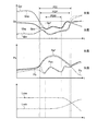
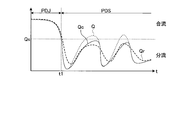
- a comparative example it is a figure which shows an example from which the discharge pressure and maximum LS pressure of a hydraulic pump, and the flow volume of a hydraulic pump and a hydraulic cylinder change with progress of time.
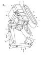
- FIG. 1 is a perspective view illustrating an example of a work machine 100 according to the embodiment.
- the work machine 100 is a hybrid hydraulic excavator will be described.
- the work machine 100 is appropriately referred to as a hydraulic excavator 100.
- a hydraulic excavator 100 includes a working machine 1 that is operated by hydraulic pressure, an upper turning body 2 that is a turning body that supports the working machine 1, a lower traveling body 3 that supports the upper turning body 2, A drive device 4 for driving the excavator 100 and an operation device 5 for operating the work machine 1 are provided.
- the upper swing body 2 has a cab 6 in which an operator is boarded and a machine room 7.
- a driver's seat 6S on which an operator is seated is provided in the cab 6.
- the machine room 7 is disposed behind the cab 6.
- At least a part of the drive device 4 including the engine and the hydraulic pump is disposed in the machine room 7.
- the lower traveling body 3 has a pair of crawlers 8.
- the hydraulic excavator 100 travels by the rotation of the crawler 8.
- the lower traveling body 3 may be a wheel (tire).
- the work machine 1 is supported by the upper swing body 2.
- the work machine 1 includes a plurality of elements.
- the plurality of elements are structures constituting the work machine.
- the plurality of elements included in the work machine 1 are a bucket 11, an arm 12 coupled to the bucket 11, and a boom 13 coupled to the arm 12.
- Bucket 11 and arm 12 are connected via a bucket pin.
- the bucket 11 is supported by the arm 12 so as to be rotatable about the rotation axis AX1.
- the arm 12 and the boom 13 are connected via an arm pin.
- the arm 12 is supported by the boom 13 so as to be rotatable about the rotation axis AX2.
- the boom 13 and the upper swing body 2 are connected via a boom pin.
- the boom 13 is supported by the upper swing body 2 so as to be rotatable about the rotation axis AX3.
- the upper swing body 2 is supported by the lower traveling body cover 3 so as to be rotatable about the swing axis RX.
- the rotation axis AX3 and the axis parallel to the turning axis RX are orthogonal.
- the axial direction of the rotation axis AX3 is appropriately referred to as the vehicle width direction of the upper swing body 2
- the direction orthogonal to both the rotation axis AX3 and the swing axis RX is appropriately referred to as the longitudinal direction of the upper swing body 2. Called.
- the direction in which the work implement 1 is present with respect to the turning axis RX is the forward direction.
- the direction in which the machine room 7 exists with respect to the rotation axis RX is the rear direction.
- the drive device 4 includes a hydraulic cylinder 20 that operates the work machine 1 and an electric swing motor 25 that generates power for rotating the upper swing body 2.
- the hydraulic cylinder 20 is driven by hydraulic oil.
- the hydraulic cylinder 20 includes a bucket cylinder 21 that operates the bucket 11, an arm cylinder 22 that operates the arm 12, and a boom cylinder 23 that operates the boom 13.
- the upper swing body 2 can be turned around the swing axis RX by the power generated by the electric swing motor 25 while being supported by the lower traveling body 3.
- the operating device 5 is disposed in the cab 6.
- the operation device 5 includes an operation member that is operated by an operator of the excavator 100.
- the operation member includes an operation lever or a joystick. When the operating device 5 is operated, the work machine 1 is operated.
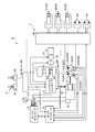
- FIG. 2 is a diagram schematically showing a control system 9 including the drive device 4 of the excavator 100 according to the embodiment.
- the control system 9 is a system for controlling the excavator 100 including the work machine 1 and a plurality of actuators that drive the work machine 1.
- the plurality of actuators are a plurality of hydraulic cylinders 20, specifically, a bucket cylinder 21, an arm cylinder 22 and a boom cylinder 23. If the work machine 1 is different, the plurality of actuators are also different.
- the plurality of actuators that drive the work machine 1 are hydraulic actuators that are driven by hydraulic oil.
- the plurality of actuators that drive the work machine 1 may be hydraulic actuators and are not limited to the hydraulic cylinder 20.
- the plurality of actuators may be hydraulic motors, for example.
- the drive device 4 includes an engine 26 that is a drive source, a generator motor 27, and a hydraulic pump 30 that discharges hydraulic oil.
- the engine 26 is, for example, a diesel engine.
- the generator motor 27 is, for example, a switched reluctance motor.
- the generator motor 27 may be a PM (Permanent Magnet) motor.
- the hydraulic pump 30 is a variable displacement hydraulic pump. In the embodiment, the hydraulic pump 30 is a swash plate hydraulic pump.
- the hydraulic pump 30 includes a first hydraulic pump 31 and a second hydraulic pump 32.
- the output shaft of the engine 26 is mechanically coupled to the generator motor 27 and the hydraulic pump 30. When the engine 26 is driven, the generator motor 27 and the hydraulic pump 30 are operated.
- the generator motor 27 may be mechanically directly connected to the output shaft of the engine 26 or may be connected to the output shaft of the engine 26 via a power transmission mechanism such as PTO (Power Take Off).
- PTO Power Take Off
- the drive device 4 includes a hydraulic drive system and an electric drive system.
- the hydraulic drive system includes a hydraulic pump 30, a hydraulic circuit 40 through which hydraulic oil discharged from the hydraulic pump 30 flows, a hydraulic cylinder 20 that operates with hydraulic oil supplied via the hydraulic circuit 40, and a travel motor 24.
- the travel motor 24 is, for example, a hydraulic motor that is driven by hydraulic oil discharged from the hydraulic pump 30.
- the electric drive system includes a generator motor 27, a capacitor 14, a transformer 14C, a first inverter 15G, a second inverter 15R, and an electric swing motor 25.
- a generator motor 27 When the engine 26 is driven, the rotor shaft of the generator motor 27 rotates. Thereby, the generator motor 27 can generate power.
- the capacitor 14 is, for example, an electric double layer capacitor.
- the hybrid controller 17 exchanges DC power between the transformer 14C and the first inverter 15G and the second inverter 15R, and also exchanges DC power between the transformer 14C and the capacitor 14.
- the electric swing motor 25 operates based on the electric power supplied from the generator motor 27 or the battery 14 and generates power for turning the upper swing body 2.
- the electric turning motor 25 is, for example, an embedded magnet synchronous electric turning motor.
- a rotation sensor 16 is provided in the electric turning motor 25.
- the rotation sensor 16 is, for example, a resolver or a rotary encoder. The rotation sensor 16 detects the rotation angle or rotation speed of the electric swing motor 25.
- the electric swing motor 25 generates regenerative energy during deceleration.
- the battery 14 is charged with regenerative energy (electric energy) generated by the electric swing motor 25.
- the capacitor 14 may be a secondary battery such as a nickel metal hydride battery or a lithium ion battery, instead of the electric double layer capacitor described above.
- the driving device 4 operates based on the operation of the operating device 5 provided in the cab 6.
- the operation amount of the operation device 5 is detected by the operation amount detection unit 28.
- the operation amount detector 28 includes a pressure sensor.
- the pilot oil pressure generated according to the operation amount of the operation device 5 is detected by the operation amount detection unit 28.
- the operation amount detection unit 28 converts the detection signal of the pressure sensor into the operation amount of the operation device 5.
- the operation amount detection unit 28 may include an electrical sensor such as a potentiometer.
- the operation amount detector 28 detects an electric signal generated according to the operation amount of the operation device 5.
- the driver's cab 6 is provided with a throttle dial 33.
- the throttle dial 33 is an operation unit for setting a fuel supply amount to the engine 26.
- the control system 9 includes a hybrid controller 17, an engine controller 18 that controls the engine 26, and a pump controller 19 that controls the hydraulic pump 30.
- the hybrid controller 17, the engine controller 18, and the pump controller 19 include a computer system.
- Each of the hybrid controller 17, the engine controller 18, and the pump controller 19 includes a processor such as a CPU (Central Processing Unit), a storage device such as a ROM (Read Only Memory) or a RAM (Random Access Memory), and an input / output interface. Device.
- a processor such as a CPU (Central Processing Unit)
- a storage device such as a ROM (Read Only Memory) or a RAM (Random Access Memory
- the hybrid controller 17, the engine controller 18, and the pump controller 19 may be integrated into one controller.
- the hybrid controller 17 includes a generator motor 27, an electric swing motor 25, an electric swing motor 25, an electric swing motor 25, an electric motor 27, an electric swing motor 25, based on detection signals from temperature sensors provided in each of the capacitor 14, the first inverter 15G, and the second inverter 15R. The temperature of the battery 14, the first inverter 15G, and the second inverter 15R is adjusted.
- the hybrid controller 17 performs charge / discharge control of the battery 14, power generation control of the generator motor 27, and assist control of the engine 26 by the generator motor 27.
- the hybrid controller 17 controls the electric swing motor 25 based on the detection signal of the rotation sensor 16.
- the engine controller 18 generates a command signal based on the set value of the throttle dial 33 and outputs the command signal to the common rail control unit 29 provided in the engine 26.
- the common rail control unit 29 adjusts the fuel injection amount for the engine 26 based on the command signal transmitted from the engine controller 18.
- the pump controller 19 is a command signal for adjusting the flow rate of hydraulic fluid discharged from the hydraulic pump 30 based on a command signal transmitted from at least one of the engine controller 18, the hybrid controller 17, and the operation amount detection unit 28. Is generated.
- the drive device 4 includes two hydraulic pumps 30, that is, a first hydraulic pump 31 and a second hydraulic pump 32. The first hydraulic pump 31 and the second hydraulic pump 32 are driven by the engine 26.
- the pump controller 19 controls the tilt angle that is the tilt angle of the swash plate 30 ⁇ / b> A of the hydraulic pump 30 to adjust the amount of hydraulic oil supplied from the hydraulic pump 30.
- the hydraulic pump 30 is provided with a swash plate angle sensor 30 ⁇ / b> S that detects the swash plate angle of the hydraulic pump 30.
- the swash plate angle sensor 30S includes a swash plate angle sensor 31S that detects the tilt angle of the swash plate 31A of the first hydraulic pump 31, and a swash plate angle sensor that detects the tilt angle of the swash plate 32A of the second hydraulic pump 32. 32S.
- the detection signal of the swash plate angle sensor 30S is output to the pump controller 19.
- the pump controller 19 calculates the pump capacity (cc / rev) of the hydraulic pump 30 based on the detection signal of the swash plate angle sensor 30S.
- the hydraulic pump 30 is provided with a servo mechanism that drives the swash plate 30A.
- the pump controller 19 controls the servo mechanism to adjust the swash plate angle.
- the hydraulic circuit 40 is provided with a pump pressure sensor for detecting the pump discharge pressure of the hydraulic pump 30. A detection signal from the pump pressure sensor is output to the pump controller 19.
- the engine controller 18 and the pump controller 19 are connected by an in-vehicle LAN (Local Area Network) such as CAN (Controller Area Network). Through the in-vehicle LAN, the engine controller 18 and the pump controller 19 can exchange data with each other.
- the pump controller 19 acquires the detection value of each sensor installed in the hydraulic circuit 40 and outputs a control command for controlling the hydraulic pump 30 and the like. Details of the control executed by the pump controller 19 will be described later.
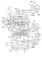
- FIG. 3 is a diagram illustrating the hydraulic circuit 40 of the drive device 4 according to the embodiment.
- the drive device 4 is supplied to the bucket cylinder 21, the arm cylinder 22, the boom cylinder 23, the first hydraulic pump 31 that discharges hydraulic oil supplied to the bucket cylinder 21 and the arm cylinder 22, and the boom cylinder 23.
- a second hydraulic pump 32 that discharges hydraulic oil.
- the hydraulic circuit 40 includes a first pump passage 41 connected to the first hydraulic pump 31 and a second pump passage 42 connected to the second hydraulic pump 32.
- the hydraulic circuit 40 includes a first supply channel 43 and a second supply channel 44 connected to the first pump channel 41, and a third supply channel 45 and a fourth supply connected to the second pump channel 42. And a flow path 46.
- the first pump flow path 41 is branched into a first supply flow path 43 and a second supply flow path 44 at the first branch portion P1.
- the second pump flow path 42 is branched into a third supply flow path 45 and a fourth supply flow path 46 at the fourth branch portion P4.
- the hydraulic circuit 40 includes a first branch channel 47 and a second branch channel 48 connected to the first supply channel 43, and a third branch channel 49 and a fourth branch connected to the second supply channel 44. And a flow path 50.
- the first supply channel 43 is branched into a first branch channel 47 and a second branch channel 48 at the second branch portion P2.
- the second supply channel 44 is branched into a third branch channel 49 and a fourth branch channel 50 at the third branch portion P3.
- the hydraulic circuit 40 includes a fifth branch channel 51 connected to the third supply channel 45 and a sixth branch channel 52 connected to the fourth supply channel 46.
- the hydraulic circuit 40 includes a first main operation valve 61 connected to the first branch flow path 47 and the third branch flow path 49, and a second main flow path connected to the second branch flow path 48 and the fourth branch flow path 50.
- the operation valve 62 includes a third main operation valve 63 connected to the fifth branch flow path 51 and the sixth branch flow path 52.
- the hydraulic circuit 40 connects the first bucket flow path 21A that connects the first main operation valve 61 and the cap-side space 21C of the bucket cylinder 21, and the first main operation valve 61 and the rod-side space 21L of the bucket cylinder 21.
- Second bucket flow path 21B The hydraulic circuit 40 connects the first arm flow path 22A that connects the second main operation valve 62 and the rod side space 22L of the arm cylinder 22, and the second main operation valve 62 and the cap side space 22C of the arm cylinder 22.
- Second arm channel 22B The hydraulic circuit 40 connects the first boom flow path 23A that connects the third main operation valve 63 and the cap side space 23C of the boom cylinder 23, and the third main operation valve 63 and the rod side space 23L of the boom cylinder 23.
- Second boom channel 23B The hydraulic circuit 40 connects the first boom flow path 23A that connects the third main operation valve 63 and the cap side space 23C of the boom cylinder 23, and the third main operation valve 63 and the rod side space 23L of the boom cylinder
- the cap side space of the hydraulic cylinder 20 is a space between the cylinder head cover and the piston.
- the rod side space of the hydraulic cylinder 20 is a space in which the piston rod is disposed.
- the hydraulic oil is supplied to the cap side space 21 ⁇ / b> C of the bucket cylinder 21, and when the bucket cylinder 21 extends, the bucket 11 performs excavation operation.
- the hydraulic oil is supplied to the rod-side space 21L of the bucket cylinder 21, and the bucket 11 performs a dumping operation when the bucket cylinder 21 is retracted.
- the working oil is supplied to the cap-side space 22C of the arm cylinder 22 and the arm 12 extends, so that the arm 12 performs an excavation operation.
- the arm 12 performs a dumping operation.
- the work machine 1 is operated by operating the operation device 5.
- the operation device 5 includes a right operation lever 5R disposed on the right side of an operator seated on the driver's seat 6S and a left operation lever 5L disposed on the left side.
- the boom 13 is lowered or raised.
- the bucket 11 performs excavation operation or dump operation.
- the arm 12 performs a dumping operation or an excavating operation.
- the upper swing body 2 turns left or right.
- the upper swing body 2 may turn right or left when the left operation lever 5L is moved in the front-rear direction, and the arm 12 may perform dumping operation or excavation operation when the left operation lever 5L is moved in the left-right direction.
- the swash plate 31A of the first hydraulic pump 31 is driven by a servo mechanism 31B.
- the servo mechanism 31B operates based on a command signal from the pump controller 19 to adjust the tilt angle of the swash plate 31A of the first hydraulic pump 31.
- the pump capacity (cc / rev) of the first hydraulic pump 31 is adjusted by adjusting the tilt angle of the swash plate 31A of the first hydraulic pump 31.
- the swash plate 32A of the second hydraulic pump 32 is driven by a servo mechanism 32B. By adjusting the tilt angle of the swash plate 32A of the second hydraulic pump 32, the pump capacity (cc / rev) of the second hydraulic pump 32 is adjusted.
- the first main operation valve 61 is a directional control valve that adjusts the direction and flow rate of hydraulic oil supplied from the first hydraulic pump 31 to the bucket cylinder 21.
- the second main operation valve 62 is a direction control valve that adjusts the direction and flow rate of hydraulic oil supplied from the first hydraulic pump 31 to the arm cylinder 22.
- the third main operation valve 63 is a direction control valve that adjusts the direction and flow rate of the hydraulic oil supplied from the second hydraulic pump 32 to the boom cylinder 23.
- the first main operation valve 61 is a slide spool type directional control valve.
- the spool of the first main operation valve 61 stops the supply of hydraulic oil to the bucket cylinder 21 to stop the bucket cylinder 21, and the first branch flow so that the hydraulic oil is supplied to the cap side space 21C.
- the second position PT2 that connects the path 21B and retracts the bucket cylinder 21 is movable.
- the first main operation valve 61 is operated so that the bucket cylinder 21 is at least one of a stopped state, an extended state, and a retracted state.
- the second main operation valve 62 has the same structure as the first main operation valve 61.
- the spool of the second main operation valve 62 has a stop position where the supply of hydraulic oil to the arm cylinder 22 is stopped to stop the arm cylinder 22, and a fourth branch flow path so that the hydraulic oil is supplied to the cap side space 22C. 50 and the second arm channel 22B are connected to each other to extend the arm cylinder 22, and the second branch channel 48 and the first arm channel 22A are supplied to the rod side space 22L.
- the second main operation valve 62 is operated so that the arm cylinder 22 is in at least one of a stopped state, an extended state, and a retracted state.
- the third main operation valve 63 has the same structure as the first main operation valve 61.
- the spool of the third main operation valve 63 has a stop position where the supply of hydraulic oil to the boom cylinder 23 is stopped to stop the boom cylinder 23, and a fifth branch flow path so that the hydraulic oil is supplied to the cap side space 23C.
- 51 and the first boom passage 23A are connected to each other to extend the boom cylinder 23, and the sixth branch passage 52 and the second boom passage 23B are supplied to the rod-side space 23L.
- the third main operation valve 63 is operated so that the boom cylinder 23 is in at least one of a stopped state, an extended state, and a retracted state.
- the first main operation valve 61 is operated by the operation device 5.
- the pilot hydraulic pressure acts on the first main operation valve 61, and the direction and flow rate of the hydraulic oil supplied from the first main operation valve 61 to the bucket cylinder 21 are determined.
- the bucket cylinder 21 operates in a moving direction corresponding to the direction of the hydraulic oil supplied to the bucket cylinder 21, and the bucket cylinder 21 operates at a cylinder speed corresponding to the flow rate of the hydraulic oil supplied to the bucket cylinder 21.
- the second main operation valve 62 is operated by the operation device 5.
- the direction and flow rate of the hydraulic oil supplied from the second main operation valve 62 to the arm cylinder 22 are determined.
- the arm cylinder 22 operates in a moving direction corresponding to the direction of the hydraulic oil supplied to the arm cylinder 22, and the arm cylinder 22 operates at a cylinder speed corresponding to the flow rate of the hydraulic oil supplied to the arm cylinder 22.
- the third main operation valve 63 is operated by the operation device 5.
- the direction and flow rate of hydraulic oil supplied from the third main operation valve 63 to the boom cylinder 23 are determined.
- the boom cylinder 23 operates in a moving direction corresponding to the direction of the hydraulic oil supplied to the boom cylinder 23, and the boom cylinder 23 operates at a cylinder speed corresponding to the flow rate of the hydraulic oil supplied to the boom cylinder 23.
- the bucket 11 When the bucket cylinder 21 operates, the bucket 11 is driven based on the moving direction of the bucket cylinder 21 and the cylinder speed.
- the arm cylinder 22 When the arm cylinder 22 operates, the arm 12 is driven based on the moving direction of the arm cylinder 22 and the cylinder speed.
- the boom 13 By operating the boom cylinder 23, the boom 13 is driven based on the moving direction and the cylinder speed of the boom cylinder 23.
- the hydraulic oil discharged from the bucket cylinder 21, the arm cylinder 22, and the boom cylinder 23 is discharged to the tank 54 via the discharge flow path 53.
- the first pump flow path 41 and the second pump flow path 42 are connected by a merging flow path 55.
- the merge channel 55 is a passage that connects the first hydraulic pump 31 and the second hydraulic pump 32. Specifically, the merging channel 55 connects the first hydraulic pump 31 and the second hydraulic pump 32 via the first pump channel 41 and the second pump channel 42.
- a first merge valve is provided in the merge channel 55.
- the first merging / dividing valve 67 is an opening / closing device that is provided in the merging channel 55 and opens and closes the merging channel 55.
- the first merging / dividing valve 67 opens and closes the merging channel 55, so that the first pump channel 41 and the second pump channel 42 are connected to each other, and the first pump channel 41 and the second pump.
- the flow is switched to a state where the flow path 42 is separated.
- a switching valve is used as the first merge / divergence valve 67, but is not limited thereto.
- the merged state means that the first pump channel 41 and the second pump channel 42 are connected via the merged channel 55, and the hydraulic oil discharged from the first pump channel 41 and the second pump channel 42 It means a state in which the discharged hydraulic oil joins at the junction / divergence valve.
- the merged state is a first state in which hydraulic oil supplied from both the first hydraulic pump 31 and the second hydraulic pump 32 is supplied to a plurality of actuators, that is, the bucket cylinder 21, the arm cylinder 22 and the boom cylinder 23.
- the diversion state means that the merging flow path 55 connecting the first pump flow path 41 and the second pump flow path 42 is separated by the merging / dividing valve, and the hydraulic oil discharged from the first pump flow path 41 and the second pump A state in which the hydraulic oil discharged from the flow path 42 is separated.
- the diversion state is a second state in which the actuator supplied with hydraulic fluid from the first hydraulic pump 31 and the actuator supplied with hydraulic fluid from the second hydraulic pump 32 are different.
- the hydraulic oil is supplied from the first hydraulic pump 31 to the bucket cylinder 21 and the arm cylinder 22, and the hydraulic oil is supplied from the second hydraulic pump 32 to the boom cylinder 23.
- the spool of the first merging / dividing valve 67 opens the merging channel 55 and connects the first pump channel 41 and the second pump channel 42, and closes the merging channel 55 and closes the first pump. It is possible to move between the flow dividing position that separates the flow path 41 and the second pump flow path 42.
- the first combined flow valve 67 is controlled so that the first pump flow path 41 and the second pump flow path 42 are in either the combined state or the divided state.
- the joining flow path 55 is closed.
- the first hydraulic pump 31 supplies hydraulic oil to the first actuator group to which at least one actuator belongs
- the second hydraulic pump 32 is connected to the actuator belonging to the first actuator group.
- the hydraulic oil is supplied to a second actuator group to which at least one actuator belongs.
- the bucket cylinder 21 and the arm cylinder 22 among the bucket cylinder 21, the arm cylinder 22, and the boom cylinder 23 belong to the first actuator group.
- the boom cylinder 23 belongs to the second actuator group.
- the hydraulic oil discharged by the first hydraulic pump 31 flows from the first pump flow path 41, the first main operation valve 61, and the first 2 is supplied to the bucket cylinder 21 and the arm cylinder 22 through the main operation valve 62. Further, the hydraulic oil discharged from the second hydraulic pump 32 is supplied to the boom cylinder 23 through the second pump flow path 42 and the third main operation valve 63.
- the first joining / dividing valve 67 is controlled by the pump controller 19 described above.
- the pump controller 19 obtains the distribution flow rate of the hydraulic oil distributed to each hydraulic cylinder 20 based on the operation state of the work machine 1 and the load of the hydraulic cylinder 20, and obtains the obtained distribution flow rate.
- This is a control device that operates the first combined / divided valve 67 based on this. Details of the pump controller 19 will be described later.
- the hydraulic circuit 40 includes a second joining / dividing valve 68 that is a switching valve.
- the second junction / divergence valve 68 is connected to a first shuttle valve 80 ⁇ / b> A provided between the first main operation valve 61 and the second main operation valve 62.
- the maximum pressures of the first main operation valve 61 and the second main operation valve 62 are selected by the first shuttle valve 80 ⁇ / b> A and output to the second combined / dividing valve 68.
- a second shuttle valve 80B is connected between the second merge / divergence valve 68 and the third main operation valve 63.
- the first shuttle valve 80A is connected to the connection port d of the second merge / divergence valve 68, and the second shuttle valve is connected to the connection port b of the second merge / divergence valve 68.
- the first oil passage 91 is connected to the connection port c of the second joining / dividing valve 68, and the second oil passage 92 is connected to the connection port a.
- the first oil passage 91 is connected to the pressure compensation valves 71 and 72 of the bucket cylinder 21, the pressure compensation valves 73 and 74 of the arm cylinder 22, and the servo mechanism 31 ⁇ / b> B of the first hydraulic pump 31.
- the second oil passage 92 is connected to the pressure compensation valves 75 and 76 of the boom cylinder 23 and the servo mechanism 32 ⁇ / b> B of the second hydraulic pump 32.
- the servo mechanism 31B is a first hydraulic pump control device that operates the first hydraulic pump 31.
- the servo mechanism 32 ⁇ / b> B is a second hydraulic pump control device that operates the second hydraulic pump 32.
- the second merging / dividing valve 68 is connected to each of the bucket cylinder 21 (first shaft), the arm cylinder 22 (second shaft), and the boom cylinder 23 (third shaft) by the first shuttle valve 80A and the second shuttle valve 80B.
- the maximum pressure of the load sensing pressure (LS pressure) in which the hydraulic oil supplied to the shaft is reduced is selected.
- the load sensing pressure is a pilot oil pressure used for pressure compensation.
- the second merge / divergence valve 68 switches the first shuttle valve 80A and the second shuttle valve 80B to the merge position PJ and the diversion position PS, and switches the first oil path 91 and the second oil path 92 to the merge position PJ. Switch to the diversion position PS.
- the second merge / divergence valve 68 switches between the merge position PJ and the diversion position PS via the intermediate position PI.
- the second combined / dividing valve 68 is controlled by the pump controller 19 described above.
- an aperture S is provided in the passage Tf connecting the connection port a and the connection port b and the passage Ts connecting the connection port c and the connection port d.
- the throttle S is not provided in the passage Tt connecting the passage Tf and the passage Ts. That is, the cross-sectional areas of the passage Tf and the passage Ts are larger than the cross-sectional area of the passage Tt.
- the first shuttle valve 80A and the second shuttle valve 80B are connected, and the first oil passage 91 and the second oil passage 92 are connected.
- the second combined / dividing valve 68 reaches the branching position PS, the first shuttle valve 80A and the second shuttle valve 80B are shut off, and the first oil passage 91 and the second oil passage 92 are shut off. In this case, the first shuttle valve 80A and the first oil passage 91 are connected, and the second shuttle valve 80B and the second oil passage 92 are blocked.
- the first shuttle valve 80A and the second shuttle valve 80B are connected with the throttle S provided, and the first oil passage 91 and the second oil passage 92 are connected to each other. Connection is made in a state where the aperture S is provided.
- the first shuttle valve 80A and the first oil passage 91 are connected in a state where the throttle S is not provided.
- the maximum LS pressure of the first to third axes is selected.
- the selected maximum LS pressure is supplied to the pressure compensation valve 70 for each of the first to third axes, the servo mechanism 31B of the first hydraulic pump 31, and the servo mechanism 32B of the second hydraulic pump 32.
- the maximum LS pressure between the first axis and the second axis is the pressure compensation valve 70 of the first axis and the second axis and the first hydraulic pump 31.
- the third shaft LS pressure is supplied to the servo mechanism 31B, and the third shaft pressure compensation valve 70 and the servo mechanism 32B of the second hydraulic pump 32 are supplied.
- the first shuttle valve 80A and the second shuttle valve 80B are output from the first main operating valve 61, the second main operating valve 62, and the third main operating valve 63.
- the pilot oil pressure indicating the maximum value is detected.
- the detected pilot oil pressure is guided to the pressure compensation valve 70 and the servo mechanism (31B, 32B) of the hydraulic pump 30 (31, 32) via the first oil passage 91 and the second oil passage 93.
- the pilot hydraulic pressure indicating the maximum value is guided to the pressure compensation valve 70 of the hydraulic cylinder 20 belonging to the first actuator group by the first oil path 91, and the hydraulic cylinder belonging to the second actuator group by the second oil path 92. 20 pressure compensation valves 70 are guided.
- the first shuttle valve 80A When the second combined flow valve 68 is at the flow dividing position PS, the first shuttle valve 80A has a pilot hydraulic pressure that indicates the maximum value among the pilot hydraulic pressures output from the first main operating valve 61 and the second main operating valve 62. To detect. The detected pilot oil pressure is guided by the first oil passage 91 to the pressure compensating valves 71, 72, 73 and 74 and the servo mechanism 31B of the first hydraulic pump 31. Further, when the second combined / dividing valve 68 is at the dividing position PS, the second shuttle valve 80B detects the pilot hydraulic pressure output from the third main operation valve 63. The detected pilot oil pressure is guided to the pressure compensation valves 75 and 76 and the servo mechanism 32B of the second hydraulic pump 32 by the second oil passage 92.
- the first shuttle valve 80A and the second shuttle valve 80B are output from the main operation valves 60 of a plurality of actuators belonging to the first actuator group and the second actuator group.
- the pilot oil pressure that shows the maximum value is selected from the pilot oil pressures.
- the selected pilot oil pressure is supplied to the plurality of pressure compensation valves 70 belonging to the first actuator group and the second actuator group and the servo mechanisms (31B, 32B) of the hydraulic pumps 30 (31, 32).
- the first shuttle valve 80A indicates the maximum value among the pilot hydraulic pressures output from the main operation valves 60 of the plurality of hydraulic cylinders 20 belonging to the first actuator group.
- the selected pilot hydraulic pressure is supplied to the plurality of pressure compensation valves 70 belonging to the second actuator group and the servo mechanism 31B of the first hydraulic pump 31. Further, when the second combined / dividing valve 68 is at the dividing position PS, the second shuttle valve 80B selects the pilot hydraulic pressure output from the main operation valve 60 of at least one actuator belonging to the second actuator group. The selected pilot hydraulic pressure is supplied to the pressure compensation valve 70 belonging to the second actuator group and the servo mechanism 32B of the second hydraulic pump 32.
- the pilot hydraulic pressure output from the first main operation valve 61 and the second main operation valve 62 is the load pressure of the actuator belonging to the first actuator group, that is, the hydraulic cylinder 20.
- the pilot hydraulic pressure output from the third main operation valve 63 is the load pressure of the actuator belonging to the second actuator group, that is, the hydraulic cylinder 20.
- the first shuttle valve 80A is a first detector that detects the maximum load pressure of the actuators belonging to the first actuator group.
- the second shuttle valve 80B is a second detector that detects the maximum load pressure of the actuators belonging to the second actuator group.
- FIG. 4 is a diagram illustrating an example in which the discharge pressure and the maximum LS pressure of the hydraulic pump and the flow rates of the hydraulic pump and the hydraulic cylinder change with the lapse of time t in the comparative example.
- FIG. 5 is a diagram showing a second combined / dividing valve 68c according to a comparative example.
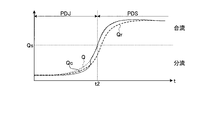
- FIG. 6 is a diagram illustrating an example in which the discharge pressure and the maximum LS pressure of the hydraulic pump and the flow rates of the hydraulic pump and the hydraulic cylinder change with the passage of time t in the embodiment.
- FIG. 4 is an example of a result obtained by the second combined / dividing valve according to the comparative example
- FIG. 6 is an exemplary result obtained by the second combined / divided valve 68 according to the embodiment.
- the second combined / dividing valve according to the comparative example is configured such that a throttle S is provided in all of the passage Tf, the passage Ts, and the passage Tt at the intermediate position PI.
- the pressure Ppf is the pressure of the hydraulic oil discharged from the first hydraulic pump 31, and the pressure Pps is the pressure of the hydraulic oil discharged from the second hydraulic pump 32.
- the pressure PLf is the maximum LS pressure given to the servo mechanism 31B of the first hydraulic pump 31, and the pressure PLs is the maximum LS pressure of the servo mechanism 32B of the second hydraulic pump 32.
- the flow rate Qpf is the flow rate of the hydraulic oil discharged from the first hydraulic pump 31, and the flow rate Qps is the flow rate of the hydraulic oil discharged from the second hydraulic pump 32.
- the flow rate Qam is the flow rate of the hydraulic oil supplied to the arm cylinder 22, and the flow rate Qbm is the flow rate of the hydraulic oil supplied to the boom cylinder 23.
- FIGS. 4 and 6 show examples in which, as time t progresses, the state changes from the diversion state STS to the merging state STJ through the intermediate state STI.
- the connection port c and the connection port d are connected, so the connection port c and the connection port d are the same.
- the maximum LS pressure applied to the servo mechanism 31B of the first hydraulic pump 31, that is, the pressure PLf is stabilized at substantially the same pressure as the pressure corresponding to the load of the hydraulic cylinder 20 belonging to the first actuator group.
- the second joining / dividing valve 68c When the second joining / dividing valve 68c is in the intermediate position PI, that is, in the intermediate state STI, the oil passage Tf that connects the connection port a and the connection port c is slightly opened. Since the throttle S is provided in the oil passage Tt that connects the oil passage Tf and the oil passage Ts, the second joining / dividing valve 68c has a pressure at the high-pressure side connection port c, that is, a pressure PLf is connected to the low-pressure side It approaches the pressure of a and decreases.
- the pressure difference between the pressure PLs and the pressure PLf in the intermediate state STI is the pressure PLs and the pressure in the separated state STS. It becomes larger than the differential pressure with PLf.
- the servo mechanism 31B operates the swash plate 31 in a direction that reduces the flow rate Qpf of the hydraulic oil discharged from the first hydraulic pump 31, and thus the flow rate Qpf decreases.
- the second combined / dividing valve 68 of the embodiment is the same as the second combined / divided valve 68c of the comparative example in the divided flow state STS, but the intermediate position PI, that is, the pressure of the connection port c when the intermediate state STI is reached.
- the behavior is different. That is, since the throttle S is not provided in the oil passage Tt that connects the connection port c and the connection port d, the second junction / divergence valve 68 connects the connection port a and the connection port c at the intermediate position PI. Even in a state where the oil passage TF is slightly opened, the pressure at the connection port c is almost the same as the pressure at the connection port d. For this reason, even if the second combined / dividing valve 68 changes from the diversion state STS to the intermediate state STI, the pressure at the connection port c, that is, the pressure PLf hardly decreases.
- the differential pressure between the pressure PLs and the pressure PLf in the intermediate state STI is almost the same as the differential pressure between the pressure PLs and the pressure PLf in the separated state STS. It becomes size. For this reason, the amount by which the swash plate 31 operates in the direction to reduce the flow rate Qpf of the hydraulic oil discharged from the first hydraulic pump 31 is smaller than that of the second combined / divided valve 68c of the comparative example. It is suppressed.
- the second merge / divergence valve 68 of the embodiment can suppress the impact generated in the excavator 100 when the diversion state STS shifts to the merge state STJ through the intermediate state STI.
- a pressure sensor 81C is attached to the first bucket channel 21A.
- a pressure sensor 81L is attached to the second bucket flow path 21B.
- the pressure sensor 81C detects the pressure in the cap side space 21C of the bucket cylinder 21.
- the pressure sensor 81L detects the pressure in the rod side space 21L of the bucket cylinder 21.
- a pressure sensor 82C is attached to the first arm channel 22A.
- a pressure sensor 82L is attached to the second arm channel 22B.
- the pressure sensor 82C detects the pressure in the cap side space 22C of the arm cylinder 22.
- the pressure sensor 82L detects the pressure in the rod side space 22L of the arm cylinder 22.
- a pressure sensor 83C is attached to the first boom channel 23A.
- a pressure sensor 83L is attached to the second boom channel 23B.
- the pressure sensor 83C detects the pressure in the cap side space 23C of the boom cylinder 23.
- the pressure sensor 83L detects the pressure in the rod side space 21L of the boom cylinder 23.
- a pressure sensor 84 is attached to the discharge port side of the first hydraulic pump 31, specifically between the first hydraulic pump 31 and the first pump flow path 41.
- the pressure sensor 84 detects the pressure of the hydraulic oil discharged from the first hydraulic pump 31.
- a pressure sensor 85 is attached to the discharge port side of the second hydraulic pump 32, specifically, between the second hydraulic pump 32 and the second pump flow path 42.
- the pressure sensor 85 detects the pressure of the hydraulic oil discharged from the second hydraulic pump 32.
- the pump controller 19 receives the detected values detected by the respective pressure sensors 81C, 81L, 82C, 82L, 83C, 83L, 84, 85.
- the hydraulic circuit 40 has a pressure compensation valve 70.
- the pressure compensation valve 70 includes a selection port for selecting communication, throttling, and blocking.
- the pressure compensation valve 70 includes a throttle valve that enables switching between cutoff, throttle, and communication with self-pressure.
- the pressure compensation valve 70 is intended to compensate the flow distribution according to the ratio of the metering opening area of each axis even when the load pressure of each axis is different. When there is no pressure compensation valve 70, most of the hydraulic oil flows through the low load shaft.
- the pressure compensation valve 70 provides pressure loss to the low load pressure shaft so that the outlet pressure of the main operating valve 60 of the low load pressure shaft is equal to the outlet pressure of the main operating valve 60 of the maximum load pressure shaft.
- the pressure compensation valve 70 includes a pressure compensation valve 71 and a pressure compensation valve 72 connected to the first main operation valve 61, a pressure compensation valve 73 and a pressure compensation valve 74 connected to the second main operation valve 62, a third A pressure compensation valve 75 and a pressure compensation valve 76 connected to the main operation valve 63 are included.
- the pressure compensation valve 71 has a differential pressure across the first main operation valve 61 in a state in which the first branch flow path 47 and the first bucket flow path 21A are connected so that hydraulic oil is supplied to the cap-side space 21C. Compensate metering differential pressure).
- the pressure compensation valve 72 has a differential pressure across the first main operation valve 61 in a state in which the third branch flow path 49 and the second bucket flow path 21B are connected so that hydraulic oil is supplied to the rod side space 21L. Compensate metering differential pressure).
- the pressure compensation valve 73 has a differential pressure across the second main operation valve 62 in a state where the second branch flow path 48 and the first arm flow path 22A are connected so that hydraulic oil is supplied to the rod side space 22L. Compensate metering differential pressure).
- the pressure compensation valve 74 has a differential pressure across the second main operation valve 62 in a state where the fourth branch flow path 50 and the second arm flow path 22B are connected so that hydraulic oil is supplied to the cap side space 22C. Compensate metering differential pressure).
- the differential pressure across the main operating valve refers to the difference between the pressure at the inlet port corresponding to the hydraulic pump side of the main operating valve and the pressure at the outlet port corresponding to the hydraulic cylinder side. It is the differential pressure for metering the flow rate.
- each of the bucket cylinder 21 and the arm cylinder 22 is provided.
- the hydraulic oil can be distributed at a flow rate corresponding to the operation amount of the operation device 5.
- the pressure compensation valve 70 can supply a flow rate based on the operation regardless of the loads of the plurality of hydraulic cylinders 20. For example, when a high load is applied to the bucket cylinder 21 and a light load is applied to the arm cylinder 22, the pressure compensation valve 70 (73, 74) disposed on the light load side is changed from the first main operation valve 61 to the bucket cylinder.
- the hydraulic oil is supplied from the second main operation valve 62 to the arm cylinder 22 regardless of the metering differential pressure ⁇ P1 generated when the hydraulic oil is supplied to the engine 21, the flow rate based on the operation amount of the second main operation valve 62 is increased.
- the metering differential pressure ⁇ P2 on the arm cylinder 22 side which is the light load side, is compensated so that the metering differential pressure ⁇ P1 on the bucket cylinder 21 side becomes substantially the same pressure.
- the pressure compensation valve 70 (71, 72) disposed on the light load side is moved from the second main operation valve 62 to the arm cylinder 22.
- a flow rate based on the operation amount of the first main operation valve 61 is supplied.
- FIG. 7 is a functional block diagram of the pump controller 19 according to the embodiment.
- the pump controller 19 includes a processing unit 19C, a storage unit 19M, and an input / output unit 19IO.
- the processing unit 19C is a processor
- the storage unit 19M is a storage device
- the input / output unit 19IO is an input / output interface device.
- the processing unit 19C includes a distribution flow rate calculation unit 19Ca, a determination unit 19Cb, a delay processing unit 19Cc, and an operation state determination unit 19Cd.
- the storage unit 19M is also used as a temporary storage unit when the processing unit 19C executes processing.
- the distribution flow rate calculation unit 19Ca obtains a distribution flow rate that is a flow rate of the hydraulic oil distributed to the bucket cylinder 21, the arm cylinder 22, and the boom cylinder 23.
- the determination unit 19Cb determines whether to open the first combined flow valve 67 based on the distribution flow rate obtained by the distribution flow rate calculation unit 19Ca.
- the delay processing unit 19Cc calculates a corrected distribution flow rate obtained by performing a delay process on the distribution flow rate determined by the distribution flow rate calculation unit 19Ca, and sends it to the determination unit 19Cb. give.
- the delay process is a process of reducing the increase amount of the distribution flow rate obtained by the distribution flow rate calculation unit 19Ca with respect to time.
- the operation state determination unit 19 ⁇ / b> Cd determines the operation state of the work machine 1 using the input given to the operation device 5.
- the processing unit 19C which is a processor, reads out from the storage unit 19M and executes a computer program for realizing the functions of the distribution flow rate calculation unit 19Ca, the determination unit 19Cb, the delay processing unit 19Cc, and the operation state determination unit 19Cd.
- the functions of the distribution flow rate calculation unit 19Ca, the determination unit 19Cb, the delay processing unit 19Cc, and the operation state determination unit 19Cd are realized. These functions are realized by a single circuit, composite circuit, programmed processor, parallel programmed processor, ASIC (Application Specific Integrated Circuit), FPGA (Field Programmable Gate Array), or a processing circuit that combines these. May be.
- Pressure sensors 81C, 81L, 82C, 82L, 83C, 83L, 84, 85, 86, 87 and 88, a first combined / divided valve 67, and a second combined / divided valve 68 are connected to the input / output unit 19IO.
- the pressure sensors 86, 87 and 88 are pressure sensors included in the operation amount detection unit 28.
- the pressure sensor 86 detects a pilot hydraulic pressure when an input for operating the bucket 11 is given to the operating device 5.
- the pressure sensor 87 detects the pilot oil pressure when given to the operating device 5 for operating the arm 12.
- the pressure sensor 88 detects the pilot hydraulic pressure when an input for operating the boom 13 is given to the operating device 5.
- the pump controller 19, more specifically, the processing unit 19C acquires the detection values of the pressure sensors 81C, 81L, 82C, 82L, 83C, 83L, 84, 85, 86, 87, and 88 from the input / output unit 19IO, so And control for switching between merging state and merging state.
- the control for switching between the diversion state and the merging state is control for operating at least the first merging / dividing valve 67, and further includes control for operating the second merging / dividing valve 68. Next, control for opening and closing the first combined / dividing valve 67 will be described.
- the pump controller 19 obtains the operation state of the work machine 1 based on the detection values of the pressure sensors 86, 87 and 88 of the operation device 5. Further, the pump controller 19 obtains the distribution flow rate of the hydraulic oil distributed to the bucket cylinder 21, the arm cylinder 22 and the boom cylinder 23 from the detection values of the pressure sensors 81C, 81L, 82C, 82L, 83C and 83L.
- the pump controller 19 compares the obtained distribution flow rate with the threshold value of the flow rate of the hydraulic oil used when determining whether or not to operate the first combined flow valve 67, and when the distribution flow rate is equal to or less than the threshold value.
- the first combined / dividing valve 67 is closed to establish a diversion state.
- the pump controller 19 opens the first merging / dividing valve 67 when the obtained distribution flow rate is larger than the threshold value, and sets the merging state.
- the threshold value is determined based on the flow rate of hydraulic fluid that can be supplied by the first hydraulic pump 31 or the flow rate of hydraulic fluid that can be supplied by the second hydraulic pump 32.
- the distribution flow rate can be obtained by Expression (1).
- Qd is the required flow rate
- PP is the pressure of the hydraulic oil discharged from the hydraulic pump 30
- ⁇ PA is the set differential pressure.
- the first main operation valve 61, the second main operation valve 62, and the third main operation valve 63 are configured so that the differential pressure between the inlet side and the outlet side is constant.
- This differential pressure is the set differential pressure ⁇ PA, which is set in advance for each of the first main operation valve 61, the second main operation valve 62, and the third main operation valve 63 and stored in the storage unit 19M of the pump controller 19. .
- the equation (1) includes the required flow rate Qd determined by the operation state of the work implement 1. As described above, the distribution flow rate Q is obtained in consideration of the operation state of the work machine 5, and therefore, the diversion state and the merging state can be switched with high accuracy.
- Q Qd ⁇ ⁇ (PP / ⁇ PL) (1)
- the distribution flow rate may be obtained by Expression (2).
- LA in the formula (2) is a load of the hydraulic cylinder 20. Considering the load of the hydraulic cylinder 20, the accuracy of the distribution flow rate Q is improved.
- the load LA may be an actual load of each hydraulic cylinder 20, may be a predetermined constant, or may be zero.
- Expression (2) becomes Expression (1).
- Q Qd ⁇ ⁇ ⁇ (PP ⁇ LA) / ⁇ PL ⁇ (2)
- the distribution flow rate Q is obtained for each hydraulic cylinder 20, that is, for each bucket cylinder 21, arm cylinder 22, and boom cylinder 23.
- the distribution flow rate of the bucket cylinder 21 is Qbk
- the distribution flow rate of the arm cylinder 22 is Qa
- the distribution flow rate of the boom cylinder 23 is Qb
- the distribution flow rates Qbk, Qa and Qb can be obtained from Equations (3) to (5).
- Qbk Qdbk ⁇ ⁇ ⁇ (PP ⁇ LAbk) / ⁇ PL ⁇ (3)
- Qa Qda ⁇ ⁇ ⁇ (PP ⁇ LAa) / ⁇ PL ⁇ (4)
- Qb Qdb ⁇ ⁇ ⁇ (PP ⁇ LAb) / ⁇ PL ⁇ (5)
- Qdbk is a required flow rate of the bucket cylinder 21 and LAbk is a load of the bucket cylinder 21.
- Qda is a required flow rate of the arm cylinder 22
- LAa is a load of the arm cylinder 22.
- Qdb is the required flow rate of the boom cylinder 23
- LAb is the load of the boom cylinder 23.
- the set differential pressure ⁇ PL includes the first main operation valve 61 that supplies and discharges hydraulic oil to the bucket cylinder 21, the second main operation valve 62 that supplies and discharges hydraulic oil to the arm cylinder 22, and the hydraulic oil to the boom cylinder 23. The same value is used for the third main operation valve 63 for supplying and discharging oil.
- the load LAbk, the load LAa, and the load LAb may be constants or zero.
- the distribution flow rate Q is determined based on the required flow rate Qd, that is, based on the operating state of the work machine 5.
- the load LAbk, the load LAa, and the load LAb are actual loads of the bucket cylinder 21, the arm cylinder 22, and the boom cylinder 23, the distribution flow rate Q is determined based on the operation state of the work machine 5 and the load of the hydraulic cylinder 20. .
- the required flow rates Qdbk, Qda, and Qdb are obtained based on pilot oil pressures detected by the pressure sensors 86, 87, and 88 included in the operation amount detection unit 28 of the operation device 5.
- the pilot oil pressure detected by the pressure sensors 86, 87 and 88 corresponds to the operation state of the work machine 1.
- the distributed flow rate calculation unit 19Ca converts the pilot hydraulic pressure into the spool stroke of the main operation valve 60, and obtains the required flow rates Qdbk, Qda, and Qdb from the obtained spool stroke.
- the relationship between the pilot hydraulic pressure and the spool stroke of the main operation valve 60 and the relationship between the spool stroke of the main operation valve 60 and the required flow rates Qdbk, Qda, and Qdb are described in the conversion table, respectively.
- the conversion table is stored in the storage unit 19M.
- the required flow rates Qdbk, Qda, and Qdb are obtained based on the operating state of the work machine 1.
- the distribution flow rate calculation unit 19Ca acquires the detection value of the pressure sensor 86 that detects the pilot oil pressure corresponding to the operation of the bucket 11, and converts it into the spool stroke of the first main operation valve 61. Then, the distribution flow rate calculation unit 19Ca obtains the required flow rate Qdbk of the bucket cylinder 21 from the obtained spool stroke.
- the distribution flow rate calculation unit 19Ca acquires the detection value of the pressure sensor 87 that detects the pilot oil pressure corresponding to the operation of the arm 12, and converts it into the spool stroke of the second main operation valve 62. Then, the distribution flow rate calculation unit 19Ca obtains the required flow rate Qda of the arm cylinder 22 from the obtained spool stroke.
- the distribution flow rate calculation unit 19Ca acquires the detection value of the pressure sensor 88 that detects the pilot hydraulic pressure corresponding to the operation of the boom 13, and converts it into the spool stroke of the third main operation valve 63. Then, the distribution flow rate calculation unit 19Ca obtains the required flow rate Qdb of the boom cylinder 23 from the obtained spool stroke.
- the direction in which the bucket 11, the arm 12, and the boom 13 operate varies depending on the direction in which the spools of the first main operation valve 61, the second main operation valve 62, and the third main operation valve 63 stroke.
- the distribution flow rate calculation unit 19Ca obtains the load LA depending on the direction in which the bucket 11, the arm 12 and the boom 13 operate, the pressure in the cap side spaces 21C, 22C and 23C or the pressure in the rod side spaces 21L, 22L and 23L. Select which one to use.
- the distribution flow rate calculation unit 19Ca uses the detection values of the pressure sensors 81C, 82C, and 83C that detect the pressures in the cap-side spaces 21C, 22C, and 23C, and loads LAbk, LAa And LAb.
- the distribution flow rate calculation unit 19Ca detects the pressure sensors 81L, 82L, and 83L that detect the pressures in the rod side spaces 21L, 22L, and 23L.
- the values LA, LAa, and LAb are obtained using the values.
- the loads LA, LAa, and LAb are the pressure of the bucket cylinder 21, the pressure of the arm cylinder 22, and the pressure of the boom cylinder 23.
- the pressure PP of the hydraulic oil discharged from the hydraulic pump 30 is unknown.
- the distribution flow rate calculation unit 19Ca gives an arbitrary initial flow rate, repeatedly performs numerical calculation so that the following equation (6) converges, and based on the distribution flow rates Qbk, Qa, and Qb when the equation (6) converges Then, the first joining / dividing valve 67 is operated.
- Qlp Qbk + Qa + Qb (6)
- the pump maximum flow rate Qmax is a value obtained by subtracting the flow rate of hydraulic oil supplied to the hydraulic swing motor when the electric swing motor 25 is replaced with the hydraulic swing motor from the flow rate obtained from the indicated value of the throttle dial 33.
- the pump maximum flow rate Qmax is a flow rate determined from the indicated value of the throttle dial 33.
- the target output of the first hydraulic pump 31 and the second hydraulic pump 32 is a value obtained by subtracting the output of the auxiliary machine of the excavator 100 from the target output of the engine 26.
- the pump target flow rate Qt is a flow rate obtained from the target output and pump pressure of the first hydraulic pump 31 and the second hydraulic pump 32.
- the pump pressure is the larger of the pressure of the hydraulic oil discharged from the first hydraulic pump 31 and the pressure of the hydraulic oil discharged from the second hydraulic pump 32.
- the determination unit 19Cb of the pump controller 19 operates the first joining / dividing valve 67 based on the result of comparing the distributed flow rates Qbk, Qa, and Qb with a threshold value. That is, the determination unit 19Cb sets the merged state or the diverted state based on the result of comparing the distribution flow rates Qbk, Qa, and Qb with the threshold values.
- the threshold is determined based on the flow rate of hydraulic oil that can be supplied by the first hydraulic pump 31 and the flow rate of hydraulic oil that can be supplied by the second hydraulic pump 32.
- the flow rate of hydraulic oil that can be supplied by one first hydraulic pump 31 (hereinafter, referred to as first supply flow rate Qsf as appropriate) is determined from the indicated value of the throttle dial 33 to the maximum capacity of the first hydraulic pump 31. It is obtained by multiplying the maximum rotational speed of the engine 26.
- the flow rate of hydraulic oil that can be supplied by one second hydraulic pump 32 (hereinafter, referred to as second supply flow rate Qss as appropriate) is determined from the indicated value of the throttle dial 33 to the maximum capacity of the second hydraulic pump 32. It is obtained by multiplying the maximum rotational speed of the engine 26.
- the threshold values of the hydraulic oil used when determining whether to operate the first combined / divided valve 67 are the first supply flow rate Qsf and the second supply flow rate Qss.
- the first hydraulic pump 31 supplies hydraulic oil to the bucket cylinder 21 and the arm cylinder 22. Therefore, if the sum of the distribution flow rate Qbk of the bucket cylinder 21 and the distribution flow rate Qa of the arm cylinder 22 is equal to or less than the first supply flow rate Qsf, the first hydraulic pump 31 alone supplies hydraulic oil to the bucket cylinder 21 and the arm cylinder 22. it can.
- the second hydraulic pump 32 supplies hydraulic oil to the boom cylinder 23. Therefore, if the distribution flow rate Qb of the boom cylinder 23 is equal to or less than the second supply flow rate Qss, the hydraulic oil can be supplied to the boom cylinder 23 by the second hydraulic pump 32 alone.
- the determination unit 19Cb determines that the sum of the distribution flow rate Qbk of the bucket cylinder 21 and the distribution flow rate Qa of the arm cylinder 22 is equal to or less than the first supply flow rate Qsf and the distribution flow rate Qb of the boom cylinder 23 is equal to or less than the second supply flow rate Qss. , And let it be in a diversion state. In this case, the determination unit 19 ⁇ / b> Cb closes the first joining / dividing valve 67.
- the determination unit 19Cb determines that the sum of the distribution flow rate Qbk of the bucket cylinder 21 and the distribution flow rate Qa of the arm cylinder 22 is not equal to or less than the first supply flow rate Qsf, or the distribution flow rate Qb of the boom cylinder 23 is not equal to or less than the second supply flow rate Qss. If any of the above is established, the merge state is established. In this case, the determination unit 19 ⁇ / b> Cb opens the first joining / dividing valve 67.
- FIG. 8 is a diagram illustrating an example in which the flow rates of the hydraulic pump and the hydraulic cylinder, the discharge pressure of the hydraulic pump, and the lever stroke change with the passage of time t.
- the horizontal axis of FIG. 8 is time t.
- the estimated value of the flow rate of the hydraulic oil supplied to the arm cylinder 22 is Qag
- the estimated value of the flow rate of the hydraulic oil supplied to the boom cylinder 23 is Qbg
- the true value of the flow rate of the hydraulic oil supplied to the arm cylinder 22 is Qar.
- the true value of the flow rate of the hydraulic oil supplied to the boom cylinder 23 is defined as Qbr.
- the estimated value Qag is the distributed flow rate Qa of the arm cylinder 22 obtained by the pump controller 19
- the estimated value Qbg is the distributed flow rate Qb of the boom cylinder 23 obtained by the pump controller 19.
- the flow rate Qpf is the flow rate of the hydraulic oil discharged from the first hydraulic pump 31, and the flow rate Qps is the flow rate of the hydraulic oil discharged from the second hydraulic pump 32.
- the pressure Ppf is the pressure of the hydraulic oil discharged from the first hydraulic pump 31, and the pressure Pps is the pressure of the hydraulic oil discharged from the second hydraulic pump 32.
- the pressure Pa is the pressure of the hydraulic oil supplied to the arm cylinder 22, and the pressure Pb is the pressure of the hydraulic oil supplied to the boom cylinder 23.
- the lever stroke Lvsa is a stroke of the operation lever when the operation device 5 is operated to operate the arm 12.
- the lever stroke Lvsb is a stroke of the operation lever when the operation device 5 is operated to operate the boom 13.
- the pump controller 19 distributes the hydraulic fluid distributed to each hydraulic cylinder 20 based on the operation state of the work machine 1 and the load of the hydraulic cylinder 20 that is an actuator that drives the work machine 1. Q is calculated. Then, the pump controller 19 switches between the merged state and the diverted state based on the obtained distributed flow rate Q and the threshold value Qs. In the embodiment, the period PDP can be in the diversion state.
- the threshold value Ps Since it is difficult to accurately estimate the flow rate of the hydraulic oil supplied to the hydraulic cylinder 20 from the pressures Ppf and Pps, the threshold value Ps needs to be increased. In this case, it is a period PDU that can be in a diversion state.
- the period PDI in which the flow can be made is a period obtained based on the true values Qar and Qbr of the flow rate of the hydraulic oil supplied to the hydraulic cylinder 20 and the threshold value Qs. Although the true values Qar and Qbr of the flow rate of the hydraulic oil supplied to the hydraulic cylinder 20 cannot actually be obtained, the period PDI based on the true values Qar and Qbr is the longest period that can be theoretically realized.
- the period in which the current can be divided is longer in the order of the period PDU based on the pressures Ppf and Pps, the period PDP by the control system 9 including the pump controller 19, and the period PDI based on the true values Qar and Qbr. Become.
- the control system 9 brings the period PDP in which the flow can be divided into a period that can be theoretically realized, that is, the period PDI based on the true values Qar and Qbr of the flow rate of the hydraulic oil supplied to the hydraulic cylinder 20. be able to.
- control system 9 can lengthen the period during which the drive device 4 is operated in the diverted state, so that it is possible to reduce the pressure loss when the high pressure hydraulic oil is depressurized and supplied to the boom cylinder 23 in the merged state. The period becomes longer.
- the second joining / dividing valve 68 has an intermediate position PI between the joining position PS and the joining position PJ.
- the timing for switching to the merge state is delayed, so that the flow rate of the hydraulic oil supplied to the hydraulic cylinder 20 is insufficient and sufficient. Work performance may not be obtained. If the second combined flow valve 68c is switched from the flow dividing position PS to the intermediate position PI at an early timing, the time for the flow dividing state is shortened, which may reduce the effect of reducing the pressure loss due to the flow dividing state.
- the determining unit 19Cb changes the first joining / dividing valve 67 from the closed state to the opened state after the second joining / dividing valve 68 reaches the joining position PJ.
- the pump controller is configured so that the pressure of the hydraulic oil discharged from the first hydraulic pump 31 and the pressure of the hydraulic oil discharged from the second hydraulic pump 32 in a state where the second combined flow valve 68 is held at the intermediate position PI.
- the differential pressure becomes equal to or less than a predetermined threshold, the holding at the intermediate position PI is terminated and set as the merge position PJ.
- the pump controller 19 opens the first joining / dividing valve 67 after setting the second joining / dividing valve 68 to the joining position PJ.
- the time required for the second combined / dividing valve 68 to reach the intermediate position PI can be set to a necessary and sufficient length, so that the impact generated in the excavator 100 is suppressed and the time for the diversion state is lengthened.
- the time during which pressure loss can be reduced can be lengthened.
- FIG. 9 is a flowchart illustrating an example of a control method according to the embodiment.
- the control method according to the embodiment is based on the operating state of the work machine 1 and the load of the hydraulic cylinder 20 that is an actuator that drives the work machine 1, and the distribution flow rate Q of the hydraulic oil distributed to each hydraulic cylinder 20. And the merging state and the diversion state are switched based on the obtained distributed flow rate Q and the threshold value.
- the control method according to the embodiment is realized by the control system 9, specifically, the pump controller 19.
- step S101 the distribution flow rate calculation unit 19Ca of the pump controller 19 calculates the distribution flow rates Qbk, Qa, and Qb.
- step S ⁇ b> 102 the determination unit 19 ⁇ / b> Cb of the pump controller 19 determines whether or not a condition for setting a diversion state is satisfied.
- step S102 Yes
- step S103 the determination unit 19Cb closes the first merging / dividing valve 67 (step S103).
- the driving device 4 operates in a diversion state.
- step S104 the determination unit 19Cb opens the first combined diversion valve 67 (step 104). By this process, the driving device 4 operates in the merged state.
- step S103 the pump controller 19 determination unit 19Cb changes the second combined diversion valve 68 from the diversion position PS to the intermediate position PI and temporarily holds it in the diversion position PS.
- the determination unit 19 ⁇ / b> Cb determines the differential pressure between the pressure of the hydraulic oil discharged from the first hydraulic pump 31 and the pressure of the hydraulic oil discharged from the second hydraulic pump 32 from the detection value of the pressure sensor 84 and the detection value of the pressure sensor 85. Ask for.
- the determination unit 19Cb ends the holding of the second merge / divergence valve 68c at the intermediate position PI, and sets the second merge / divergence valve 68 as the merge position PJ. Thereafter, the determination unit 19Cb closes the first joining / dividing valve 67.
- the distribution flow rate Q calculated by the distribution flow rate calculation unit 19Ca of the pump controller 19 tends to increase or decrease earlier than the true value Qr when the load fluctuates. For this reason, when the first combined / divided valve 67 is operated based on the distributed flow rate Q to switch between the combined state and the divided state, the combined state and the divided state are frequently switched in a short period, resulting in pressure loss due to the divided state. The reduction effect may decrease.
- FIG. 10 is a diagram showing an example of changes of the distribution flow rate Q, the corrected distribution flow rate Qc, and the actual flow rate of the actual hydraulic oil supplied to the hydraulic cylinder 20 with respect to time t.
- the driving device 4 in the period PDJ, the driving device 4 operates in the merged state.
- the driving device 4 At the timing when the period PDJ is changed to the period PDS, the driving device 4 operates in a shunt state.
- the distribution flow rate Q increases or decreases earlier than the true value Qr, and is largely calculated in the direction in which the flow rate increases.
- the distribution flow rate Q exceeds the threshold value Qs and then decreases. Is repeated.
- the merging state and the diversion state are frequently switched in a short period.
- the delay processing unit 19Cc of the pump controller 19 corrects the distribution by reducing the increase amount of the obtained distribution flow rate Q with respect to time t when the obtained distribution flow rate Q increases with the progress of time t.
- the first joining / dividing valve 67 is operated using the flow rate Qc.
- the corrected distribution flow rate Qc is, for example, the distribution flow rate Q that has been passed through a low-pass filter, but the correction distribution flow rate Qc only needs to have a smaller increase amount with respect to the time t of the distribution flow rate Q.
- the corrected distribution flow rate Qc may be a value output by the delay processing unit 19Cc by delaying the distribution flow rate Q according to the primary delay.
- the determining unit 19Cb operates the first merge / divergence valve 67 using the corrected distribution flow rate Qc to switch between the merge state and the diversion state.
- the rate of increase of the distribution flow rate Q with respect to time t decreases, so that even when the load on the hydraulic cylinder 20 frequently changes, the corrected distribution flow rate Qc.
- the control system 9 can avoid frequently switching from the diversion state to the merging state in a short period of time, so that it is possible to suppress a decrease in the pressure loss reduction effect due to the diversion state.
- the pump controller 19 when the obtained distributed flow rate Q increases with the progress of time t, the pump controller 19 operates the first combined / divided valve 67 using the corrected distributed flow rate Qc.
- the switching from the diverging state to the merging state occurs when the allocated flow rate Q exceeds the threshold value Qs, and the switching from the merging state to the diverting state occurs when the allocated flow rate Q becomes equal to or less than the threshold value Qs.
- the pump controller 19 can quickly switch from the diversion state to the merging state by operating the first merging / dividing valve 67 when the obtained distribution flow rate Q increases with the progress of time t.
- the operation of the first combined / divided valve 67 may be delayed depending on the type of work performed by the excavator 100.
- the work performed by the excavator 100 is a work for operating the work machine 1 at a high speed
- the operation of the first joining / dividing valve 67 may be delayed.
- the work machine 1 is operated at a high speed
- the operation of operating the work machine 1 at a high speed is an operation in which the flow rate supplied to the hydraulic cylinder 20 is large.
- the pump controller 19 switches between enabling and disabling the low-pass filter according to the operation state of the work machine 1 when determining whether or not to operate the first joining / dividing valve 67. Specifically, switching is made between using the corrected distribution flow Qc or the distribution flow Q not passing through the low-pass filter.
- the determination unit 19Cb operates the first merging / dividing valve 67 using the distribution flow rate Q, and the merging state and the divergence state are set. Can be switched. As a result, the speed reduction of the work machine 1 when the work machine 1 needs to be operated at a high speed is suppressed.
- the operation state determination unit 19Cd of the pump controller 19 determines the operation state of the work machine 1 based on the pilot oil pressure detected by the pressure sensors 86, 87, and 88 included in the operation amount detection unit 28 that detects the operation amount of the operation device 5. judge.
- the determination unit 19Cb operates the first combined / divided valve 67 using the distributed flow rate Q. To switch between the merged state and the diverted state.
- FIG. 11 is a diagram illustrating an example of changes of the distribution flow rate Q, the corrected distribution flow rate Qc, and the flow rate of hydraulic oil supplied to the hydraulic cylinder 20 with respect to time t of the true value Qr.
- the driving device 4 operates in a shunt state.
- the driving device 4 operates in the joined state.
- the operation state of the driving device 4 is switched from the diversion state to the merging state by comparing the corrected distribution flow rate Qc and the threshold value Qs, it cannot be switched to the merging state until after the time t1.
- the operation state of the drive device 4 is switched from the diversion state to the merging state by comparing the distribution flow rate Q and the threshold value Qs, the operation state is switched to the merging state at time t1.
- the control system 9 is an operation for operating the work machine 1 at a high speed, the flow rate required for the operation of the work machine 1 before the flow rate of the hydraulic oil supplied to the hydraulic cylinder 20 is insufficient. Since the hydraulic oil can be supplied to the hydraulic cylinder 20, the speed reduction of the work machine 1 is suppressed.
- the electric turning motor 25 turns the upper turning body 2. That is, the upper swing body 2 is driven by an actuator that does not belong to the first actuator group and the second actuator group.
- the occurrence of pressure loss in the boom cylinder 23 is suppressed. Is done.
- a pressure loss due to the pressure compensation valve occurs.
- the boom cylinder 23 is supplied with hydraulic fluid from one hydraulic pump 30 (second hydraulic pump 32), and the upper swing body 2 is rotated by the electric swing motor 25. Therefore, operability degradation and pressure loss are suppressed.
- the control system 9 calculates
- the control system 9 has a first state in which hydraulic oil supplied from both the first hydraulic pump 31 and the second hydraulic pump 32 is supplied to the plurality of hydraulic cylinders 20 based on the obtained distribution flow rate,
- the hydraulic cylinder 20 to which hydraulic oil is supplied from the first hydraulic pump 31 and the hydraulic cylinder 20 to which hydraulic oil is supplied from the second hydraulic pump 32 are switched between different second states.
- the control system 9 can expand the range in which the hydraulic oil discharged from the plurality of hydraulic pumps can be separated and supplied to the actuator when supplying the hydraulic oil to the actuator from the plurality of hydraulic pumps. . That is, since the control system 9 can extend the period during which the drive device 4 is operated in the second state, the pressure loss when reducing the high pressure hydraulic oil and supplying it to the boom cylinder 23 in the first state is reduced. The period that can be increased.
- the control system 9 can improve the accuracy of the distribution flow rate by obtaining the distribution flow rate based on the operation state of the work machine 1 and the load of the actuator. As a result, the threshold value of the flow rate of the hydraulic oil used when determining whether or not to operate the first joining / dividing valve 67 serving as the opening / closing device can be brought close to the theoretical value. For this reason, the control system 9 can reduce the pressure loss at the time of operating the drive device 4 in the second state for a longer period and reducing the pressure of the high-pressure hydraulic oil and supplying it to the boom cylinder 23 in the first state. The period can be made longer.
- the driving device 4 (hydraulic circuit 40) is applied to the excavator 100.
- the target to which the drive device 4 is applied is not limited to the hydraulic excavator, and can be widely applied to hydraulically driven work machines other than the hydraulic excavator.
- the excavator 100 which is a work machine is a hybrid system, but the work machine may not be a hybrid system.
- the first hydraulic pump 31 and the second hydraulic pump 32 are swash plate type pumps, but are not limited thereto.
- the loads LA, LAa, and LAb are the pressure of the bucket cylinder 21, the pressure of the arm cylinder 22, and the pressure of the boom cylinder 23, but are not limited thereto.
- the pressure of the bucket cylinder 21, the pressure of the arm cylinder 22, and the pressure of the boom cylinder 23 corrected by the area ratio of the throttle valves included in the pressure compensation valves 71 to 76 may be used as the loads LA, LAa, and LAb.
- the threshold value Qs used when determining whether or not to operate the first combined flow valve 67 is the first supply flow rate Qsf and the second supply flow rate Qss, but is not limited thereto.
- the threshold Qs may be a flow rate smaller than the first supply flow rate Qsf and the second supply flow rate Qss.
- the pump controller 19 includes the delay processing unit 19Cc and the operation state determination unit 19Cd, but the pump controller 19 may not include both the delay processing unit 19Cc and the operation state determination unit 19Cd.
- the state determination unit 19Cd may not be provided.
- the first state and the second state are switched by operating the first joining / dividing valve 67.
- the switching between the first state and the second state is performed by the operation of the first joining / dividing valve 67. It is not limited to that by.
- the elements of the work machine 1 are the bucket 8, the arm 7, and the boom 6. However, the elements of the work machine 1 are not limited to these.
Abstract
Description
図1は、実施形態に係る作業機械100の一例を示す斜視図である。実施形態においては、作業機械100がハイブリッド方式の油圧ショベルである例について説明する。以下の説明において、作業機械100を適宜、油圧ショベル100、と称する。
図2は、実施形態に係る油圧ショベル100の駆動装置4を含む制御システム9を模式的に示す図である。制御システム9は、作業機1及び作業機1を駆動する複数のアクチュエータを備える油圧ショベル100を制御するためのシステムである。複数のアクチュエータは、複数の油圧シリンダ20、詳細にはバケットシリンダ21、アームシリンダ22及びブームシリンダ23である。作業機1が異なれば、複数のアクチュエータも異なる。実施形態において、作業機1を駆動する複数のアクチュエータは、作動油によって駆動される油圧式のアクチュエータである。作業機1を駆動する複数のアクチュエータは、油圧式のアクチュエータであればよく、油圧シリンダ20には限定されない。複数のアクチュエータは、例えば、油圧モータであってもよい。
図3は、実施形態に係る駆動装置4の油圧回路40を示す図である。駆動装置4は、バケットシリンダ21と、アームシリンダ22と、ブームシリンダ23と、バケットシリンダ21及びアームシリンダ22に供給される作動油を吐出する第1油圧ポンプ31と、ブームシリンダ23に供給される作動油を吐出する第2油圧ポンプ32とを備える。
油圧回路40は、切替弁である第2合分流弁68を有する。第2合分流弁68は、第1主操作弁61と第2主操作弁62との間に設けられた第1シャトル弁80Aと接続される。第1主操作弁61と第2主操作弁62との最大圧力が第1シャトル弁80Aで選択され第2合分流弁68へ出力される。また、第2合分流弁68と第3主操作弁63との間に第2シャトル弁80Bが接続される。第1シャトル弁80Aは第2合分流弁68の接続口dに接続され、第2シャトル弁は第2合分流弁68の接続口bに接続される。
第1バケット流路21Aには、圧力センサ81Cが取り付けられる。第2バケット流路21Bには、圧力センサ81Lが取り付けられる。圧力センサ81Cは、バケットシリンダ21のキャップ側空間21C内の圧力を検出する。圧力センサ81Lは、バケットシリンダ21のロッド側空間21L内の圧力を検出する。
油圧回路40は、圧力補償弁70を有する。圧力補償弁70は、連通と絞りと遮断とを選択するための選択ポートを備える。圧力補償弁70は、自己圧で遮断と、絞りと、連通との切り替えを可能とする、絞り弁を含む。圧力補償弁70は、各軸の負荷圧が異なっていても、各軸のメータリング開口面積の比率に応じて流量分配を補償することを目的としている。圧力補償弁70がない場合、低負荷側の軸にほとんどの作動油が流れてしまう。圧力補償弁70は、低負荷圧の軸の主操作弁60の出口圧力が、最大負荷圧の軸の主操作弁60の出口圧力と同等になるように、低負荷圧の軸に圧力損失を作用させることで、各主操作弁60の出口圧力が同一となるため、流量分配の機能を実現する。
図7は、実施形態に係るポンプコントローラ19の機能ブロック図である。ポンプコントローラ19は、処理部19Cと、記憶部19Mと、入出力部19IOとを有する。処理部19Cはプロセッサであり、記憶部19Mは記憶装置であり、入出力部19IOは入出力インターフェース装置である。処理部19Cは、配分流量演算部19Caと、決定部19Cbと、遅れ処理部19Ccと、操作状態判定部19Cdとを含む。記憶部19Mは、処理部19Cが処理を実行する際の一時記憶部としても使用される。
ポンプコントローラ19は、操作装置5の圧力センサ86,87及び88の検出値に基づいて作業機1の操作状態を求める。また、ポンプコントローラ19は、圧力センサ81C,81L,82C,82L,83C及び83Lの検出値から、バケットシリンダ21、アームシリンダ22及びブームシリンダ23に配分される作動油の配分流量を求める。
Q=Qd×√(PP/ΔPL)・・・(1)
Q=Qd×√{(PP-LA)/ΔPL}・・・(2)
Qbk=Qdbk×√{(PP-LAbk)/ΔPL}・・・(3)
Qa=Qda×√{(PP-LAa)/ΔPL}・・・(4)
Qb=Qdb×√{(PP-LAb)/ΔPL}・・・(5)
Qlp=Qbk+Qa+Qb・・・(6)
第2合分流弁68は、分流位置PSと合流位置PJとの間に中間位置PIを有する。ポンプコントローラ19、詳細には処理部19Cにおける決定部19Cbは、分流状態から合流状態に切り替える際に、第2合分流弁68を分流位置PSから中間位置PIにした後、中間位置PIで一旦保持してから合流位置PJにする。このような制御によって、分流状態から合流状態へ切り替わる際に油圧ショベル100に発生する衝撃が抑制される。
ポンプコントローラ19の配分流量演算部19Caが求める配分流量Qは、負荷が変動した場合、真値Qrと比較して、値が早めに増減する傾向がある。このため、配分流量Qに基づいて第1合分流弁67を動作させて合流状態と分流状態とを切り替えると、短い期間に頻繁に合流状態と分流状態とが切り替わり、結果として分流状態による圧力損失の低減効果が減少することがある。
2 上部旋回体
3 下部走行体
4 駆動装置
5 操作装置
9 制御システム
11 バケット
12 アーム
13 ブーム
14 蓄電器
17 ハイブリッドコントローラ
18 エンジンコントローラ
19 ポンプコントローラ
19C 処理部
19M 記憶部
19Ca 配分流量演算部
19Cb 決定部
19Cc 遅れ処理部
19Cd 操作状態判定部
19IO 入出力部
20 油圧シリンダ
21 バケットシリンダ
22 アームシリンダ
23 ブームシリンダ
24 走行モータ
25 電動旋回モータ
26 エンジン
28 操作量検出部
29 コモンレール制御部
30 油圧ポンプ
31 第1油圧ポンプ
32 第2油圧ポンプ
33 スロットルダイヤル
40 油圧回路
55 合流流路
60 主操作弁
61 第1主操作弁
62 第2主操作弁
63 第3主操作弁
67 第1合分流弁
68 第2合分流弁
81C,81L,82C,82L,83C,83L,84,85,86,87,88 圧力センサ
100 油圧ショベル(作業機械)
LA,LAa,LAb,LAbk 負荷
Q,Qa,Qb,Qbk 配分流量
Qs 閾値
Claims (12)
- 複数の要素を含む作業機及び複数の前記要素を駆動する複数のアクチュエータを備える作業機械を制御するための制御システムにおいて、
複数の前記アクチュエータのうち少なくとも1つに作動油を供給する第1油圧ポンプ及び第2油圧ポンプと、
前記作業機の操作状態に基づいてそれぞれの前記アクチュエータに配分される作動油の配分流量を求め、得られた前記配分流量に基づいて、前記第1油圧ポンプ及び前記第2油圧ポンプの両方から供給される前記作動油を前記複数のアクチュエータに供給する第1状態と、前記第1油圧ポンプから前記作動油が供給される前記アクチュエータと前記第2油圧ポンプから前記作動油が供給される前記アクチュエータとが異なる第2状態とを切り替える制御装置と、
を含む、制御システム。 - 前記制御装置は、
前記作業機の操作状態と、前記アクチュエータの負荷とに基づいて前記配分流量を求める、請求項1に記載の制御システム。 - 前記第1油圧ポンプと前記第2油圧ポンプとを接続する通路と、
前記通路に設けられて、前記通路を開閉する開閉装置と、を有し、
前記通路が閉じられた状態において、前記第1油圧ポンプは、少なくとも1つの前記アクチュエータが属する第1アクチュエータ群に作動油を供給し、前記第2油圧ポンプは、前記第1アクチュエータ群に属する前記アクチュエータとは異なる、少なくとも1つの前記アクチュエータが属する第2アクチュエータ群に作動油を供給し、
前記制御装置は、
前記配分流量に基づいて前記開閉装置を動作させることにより、前記第1状態と前記第2状態とを切り替える、請求項1又は請求項2に記載の制御システム。 - 前記制御装置は、
前記配分流量と、前記第1油圧ポンプが1台で供給できる作動油の流量及び前記第2油圧ポンプが1台で供給できる作動油の流量に基づいて定められた閾値とを比較した結果に基づいて、前記開閉装置を動作させる、請求項3に記載の制御システム。 - 前記制御装置は、
得られた前記配分流量が時間の進行とともに増加する場合、得られた前記配分流量の時間に対する増加量を小さくした修正配分流量を用いて、前記開閉装置を動作させる、請求項3又は請求項4に記載の制御システム。 - 前記制御装置は、
前記開閉装置を動作させるか否かを決定する際に、前記操作状態に応じて、前記修正配分流量を用いるか又は前記配分流量を用いるかを切り替える、請求項5に記載の制御システム。 - 複数の前記要素は、バケット、前記バケットと連結されるアーム、及び前記アームと連結されるブームであり、
複数の前記アクチュエータは、前記バケットを動作させるバケットシリンダ、前記アームを動作させるアームシリンダ、及び前記ブームを動作させるブームシリンダを有し、
前記第1アクチュエータ群には前記バケットシリンダ及び前記アームシリンダが属し、前記第2アクチュエータ群には前記ブームシリンダが属する、請求項3から請求項6のいずれか1項に記載の制御システム。 - 前記作業機械は、前記作業機を支持する旋回体を有し、
前記旋回体は、前記第1アクチュエータ群及び前記第2アクチュエータ群に属さないアクチュエータによって駆動される、請求項3から請求項7のいずれか1項に記載の制御システム。 - 前記第1アクチュエータ群に属する前記アクチュエータの最大負荷圧を検出する第1検出器と、
前記第1検出器によって検出された最大負荷圧を、前記第1油圧ポンプを動作させる第1油圧ポンプ制御装置に導く第1油路と、
前記第2アクチュエータ群に属する前記アクチュエータの最大負荷圧を検出する第2検出器と、
前記第2検出器によって検出された最大負荷圧を、前記第2油圧ポンプを動作させる第2油圧ポンプ制御装置に導く第2油路と、
前記第1検出器と前記第2検出器との接続又は遮断を切り替えるとともに、前記第1油路と前記第2油路との接続又は遮断を切り替える切替弁と、を有し、
前記切替弁は、接続と遮断との中間の状態において、前記第1負荷検出器と前記第1油路とを絞りが設けられない状態で接続し、前記第1検出器と前記第2検出器とを絞りが設けられた状態で接続し、前記第1油路と前記第2油路とを絞りが設けられた状態で接続する、請求項3から請求項8のいずれか1項に記載の制御システム。 - 前記制御装置は、
前記切替弁を前記非接続状態から前記中間の状態に切り替えた後、前記中間の状態を保持し、
前記第1油圧ポンプが吐出する作動油の圧力と、前記第2油圧ポンプが吐出する作動油の圧力との差圧が予め定められた閾値以下になった場合に前記中間の状態での保持を終了して、前記接続状態とし、
前記切替弁が前記接続状態になった後に前記開閉装置を開く、請求項9に記載の制御システム。 - 請求項1から請求項10のいずれか1項に記載の制御システムを有する、作業機械。
- 作業機を構成する複数の要素を駆動する複数のアクチュエータのうち少なくとも1つに作動油を供給する第1油圧ポンプ及び第2油圧ポンプを含む作業機械を制御するにあたって、
前記作業機の操作状態に基づいてそれぞれの前記アクチュエータに配分される作動油の配分流量を求めることと、
得られた前記配分流量に基づいて、前記第1油圧ポンプ及び前記第2油圧ポンプの両方から供給される前記作動油を前記複数のアクチュエータに供給する第1状態と、前記第1油圧ポンプから前記作動油が供給される前記アクチュエータと前記第2油圧ポンプから前記作動油が供給される前記アクチュエータとが異なる第2状態とを切り替えることと、
を含む、制御方法。
Priority Applications (6)
| Application Number | Priority Date | Filing Date | Title |
|---|---|---|---|
| JP2016553673A JP6244475B1 (ja) | 2016-07-29 | 2016-07-29 | 制御システム、作業機械及び制御方法 |
| CN201680001241.5A CN108138805B (zh) | 2016-07-29 | 2016-07-29 | 控制系统、作业机械及控制方法 |
| DE112016000084.7T DE112016000084B4 (de) | 2016-07-29 | 2016-07-29 | Steuersystem, Arbeitsmaschine und Steuerverfahren |
| PCT/JP2016/072447 WO2018020689A1 (ja) | 2016-07-29 | 2016-07-29 | 制御システム、作業機械及び制御方法 |
| KR1020177003399A KR101865285B1 (ko) | 2016-07-29 | 2016-07-29 | 제어 시스템, 작업 기계 및 제어 방법 |
| US15/501,269 US10344781B2 (en) | 2016-07-29 | 2016-07-29 | Control system, work machine, and control method |
Applications Claiming Priority (1)
| Application Number | Priority Date | Filing Date | Title |
|---|---|---|---|
| PCT/JP2016/072447 WO2018020689A1 (ja) | 2016-07-29 | 2016-07-29 | 制御システム、作業機械及び制御方法 |
Publications (1)
| Publication Number | Publication Date |
|---|---|
| WO2018020689A1 true WO2018020689A1 (ja) | 2018-02-01 |
Family
ID=60570325
Family Applications (1)
| Application Number | Title | Priority Date | Filing Date |
|---|---|---|---|
| PCT/JP2016/072447 WO2018020689A1 (ja) | 2016-07-29 | 2016-07-29 | 制御システム、作業機械及び制御方法 |
Country Status (6)
| Country | Link |
|---|---|
| US (1) | US10344781B2 (ja) |
| JP (1) | JP6244475B1 (ja) |
| KR (1) | KR101865285B1 (ja) |
| CN (1) | CN108138805B (ja) |
| DE (1) | DE112016000084B4 (ja) |
| WO (1) | WO2018020689A1 (ja) |
Families Citing this family (4)
| Publication number | Priority date | Publication date | Assignee | Title |
|---|---|---|---|---|
| JP7253949B2 (ja) * | 2019-03-25 | 2023-04-07 | 株式会社小松製作所 | 作業機械、システムおよび作業機械の制御方法 |
| JP7253478B2 (ja) * | 2019-09-25 | 2023-04-06 | 日立建機株式会社 | 作業機械 |
| CN111102253A (zh) * | 2019-12-25 | 2020-05-05 | 长沙中达智能科技有限公司 | 一种液压驱动机构速度的控制装置与方法 |
| CN113550374B (zh) * | 2021-06-30 | 2022-08-12 | 徐州徐工挖掘机械有限公司 | 挖掘机作业的流量控制方法及提高动臂提升速度的方法 |
Citations (3)
| Publication number | Priority date | Publication date | Assignee | Title |
|---|---|---|---|---|
| WO2007132691A1 (ja) * | 2006-05-15 | 2007-11-22 | Komatsu Ltd. | 油圧走行車両および油圧走行車両の制御方法 |
| JP4272207B2 (ja) * | 2003-11-14 | 2009-06-03 | 株式会社小松製作所 | 建設機械の油圧制御装置 |
| JP2013532260A (ja) * | 2010-05-28 | 2013-08-15 | キャタピラー インコーポレイテッド | 器具フローと操舵フローを共有する油圧システム |
Family Cites Families (14)
| Publication number | Priority date | Publication date | Assignee | Title |
|---|---|---|---|---|
| JP3891893B2 (ja) | 2002-07-01 | 2007-03-14 | 株式会社小松製作所 | 油圧駆動装置 |
| CN101180469B (zh) | 2005-05-18 | 2010-10-13 | 株式会社小松制作所 | 施工机械的油压控制装置 |
| DE602006003293D1 (de) * | 2005-06-02 | 2008-12-04 | Caterpillar Mitsubishi Ltd | Arbeitsmaschine |
| CN2923463Y (zh) * | 2006-07-28 | 2007-07-18 | 江西盖特方向机有限公司 | 双向缓冲负荷传感大流量放大全液压转向器 |
| JP5356159B2 (ja) * | 2009-09-02 | 2013-12-04 | 日立建機株式会社 | 油圧作業機の油圧駆動装置 |
| WO2011132691A1 (ja) * | 2010-04-23 | 2011-10-27 | コニカミノルタオプト株式会社 | 光ピックアップ装置用の対物レンズ、光ピックアップ装置及び光情報記録再生装置 |
| JP5572586B2 (ja) * | 2011-05-19 | 2014-08-13 | 日立建機株式会社 | 作業機械の油圧駆動装置 |
| US9145660B2 (en) * | 2012-08-31 | 2015-09-29 | Caterpillar Inc. | Hydraulic control system having over-pressure protection |
| US20140283915A1 (en) * | 2013-03-21 | 2014-09-25 | Caterpillar Inc. | Hydraulic Control System Having Relief Flow Capture |
| US20140283676A1 (en) * | 2013-03-21 | 2014-09-25 | Caterpillar Inc. | Fluid Regeneration in a Hydraulic System |
| CN104221593A (zh) * | 2013-06-21 | 2014-12-24 | 广西壮族自治区农业机械研究院 | 甘蔗收割机液压行走系统差速及同步控制装置 |
| CN203353185U (zh) * | 2013-06-21 | 2013-12-25 | 广西壮族自治区农业机械研究院 | 甘蔗收割机液压行走系统差速及同步控制装置 |
| CN104675768B (zh) * | 2015-02-09 | 2016-08-17 | 扬州金威环保科技有限公司 | 小型全液压全轮驱动扫地车行走液压系统 |
| CN105634971B (zh) * | 2015-12-31 | 2019-03-08 | 微梦创科网络科技(中国)有限公司 | 一种分配流量的方法及装置 |
-
2016
- 2016-07-29 KR KR1020177003399A patent/KR101865285B1/ko active IP Right Grant
- 2016-07-29 US US15/501,269 patent/US10344781B2/en active Active
- 2016-07-29 CN CN201680001241.5A patent/CN108138805B/zh active Active
- 2016-07-29 JP JP2016553673A patent/JP6244475B1/ja active Active
- 2016-07-29 WO PCT/JP2016/072447 patent/WO2018020689A1/ja active Application Filing
- 2016-07-29 DE DE112016000084.7T patent/DE112016000084B4/de active Active
Patent Citations (3)
| Publication number | Priority date | Publication date | Assignee | Title |
|---|---|---|---|---|
| JP4272207B2 (ja) * | 2003-11-14 | 2009-06-03 | 株式会社小松製作所 | 建設機械の油圧制御装置 |
| WO2007132691A1 (ja) * | 2006-05-15 | 2007-11-22 | Komatsu Ltd. | 油圧走行車両および油圧走行車両の制御方法 |
| JP2013532260A (ja) * | 2010-05-28 | 2013-08-15 | キャタピラー インコーポレイテッド | 器具フローと操舵フローを共有する油圧システム |
Also Published As
| Publication number | Publication date |
|---|---|
| JPWO2018020689A1 (ja) | 2018-07-26 |
| DE112016000084T5 (de) | 2018-04-12 |
| US10344781B2 (en) | 2019-07-09 |
| CN108138805B (zh) | 2020-02-11 |
| CN108138805A (zh) | 2018-06-08 |
| DE112016000084B4 (de) | 2019-09-12 |
| US20180216637A1 (en) | 2018-08-02 |
| JP6244475B1 (ja) | 2017-12-06 |
| KR101865285B1 (ko) | 2018-06-07 |
| KR20180022623A (ko) | 2018-03-06 |
Similar Documents
| Publication | Publication Date | Title |
|---|---|---|
| JP6087034B1 (ja) | 制御システム、作業機械、及び制御方法 | |
| KR101942603B1 (ko) | 건설 기계 | |
| KR101834589B1 (ko) | 선회체를 갖는 건설 기계 | |
| JP6244475B1 (ja) | 制御システム、作業機械及び制御方法 | |
| JP6145229B1 (ja) | 制御システム、作業機械、及び制御方法 | |
| US10407875B2 (en) | Control system and work machine | |
| JP5573824B2 (ja) | 油圧エネルギー回生装置 | |
| JP6023391B2 (ja) | 建設機械の駆動装置 | |
| JP2004197825A (ja) | 液圧駆動装置 | |
| JP6360189B1 (ja) | 制御システム、作業機械、及び制御方法 | |
| JP5872170B2 (ja) | 建設機械の制御装置 | |
| JP6612384B2 (ja) | 制御システム、作業機械、及び制御方法 | |
| CN114746612A (zh) | 作业机 |
Legal Events
| Date | Code | Title | Description |
|---|---|---|---|
| ENP | Entry into the national phase |
Ref document number: 2016553673 Country of ref document: JP Kind code of ref document: A |
|
| WWE | Wipo information: entry into national phase |
Ref document number: 15501269 Country of ref document: US |
|
| WWE | Wipo information: entry into national phase |
Ref document number: 112016000084 Country of ref document: DE |
|
| 121 | Ep: the epo has been informed by wipo that ep was designated in this application |
Ref document number: 16910592 Country of ref document: EP Kind code of ref document: A1 |
|
| 122 | Ep: pct application non-entry in european phase |
Ref document number: 16910592 Country of ref document: EP Kind code of ref document: A1 |