EP4407794A1 - Elektronische vorrichtung - Google Patents
Elektronische vorrichtung Download PDFInfo
- Publication number
- EP4407794A1 EP4407794A1 EP23878390.6A EP23878390A EP4407794A1 EP 4407794 A1 EP4407794 A1 EP 4407794A1 EP 23878390 A EP23878390 A EP 23878390A EP 4407794 A1 EP4407794 A1 EP 4407794A1
- Authority
- EP
- European Patent Office
- Prior art keywords
- antenna body
- electronic device
- support
- support rib
- support ribs
- Prior art date
- Legal status (The legal status is an assumption and is not a legal conclusion. Google has not performed a legal analysis and makes no representation as to the accuracy of the status listed.)
- Pending
Links
Images


Classifications
-
- H—ELECTRICITY
- H01—ELECTRIC ELEMENTS
- H01Q—ANTENNAS, i.e. RADIO AERIALS
- H01Q1/00—Details of, or arrangements associated with, antennas
- H01Q1/12—Supports; Mounting means
- H01Q1/22—Supports; Mounting means by structural association with other equipment or articles
-
- H—ELECTRICITY
- H01—ELECTRIC ELEMENTS
- H01Q—ANTENNAS, i.e. RADIO AERIALS
- H01Q1/00—Details of, or arrangements associated with, antennas
- H01Q1/12—Supports; Mounting means
- H01Q1/1207—Supports; Mounting means for fastening a rigid aerial element
-
- H—ELECTRICITY
- H01—ELECTRIC ELEMENTS
- H01Q—ANTENNAS, i.e. RADIO AERIALS
- H01Q1/00—Details of, or arrangements associated with, antennas
- H01Q1/27—Adaptation for use in or on movable bodies
- H01Q1/32—Adaptation for use in or on road or rail vehicles
-
- H—ELECTRICITY
- H01—ELECTRIC ELEMENTS
- H01Q—ANTENNAS, i.e. RADIO AERIALS
- H01Q1/00—Details of, or arrangements associated with, antennas
- H01Q1/36—Structural form of radiating elements, e.g. cone, spiral, umbrella; Particular materials used therewith
-
- H—ELECTRICITY
- H01—ELECTRIC ELEMENTS
- H01Q—ANTENNAS, i.e. RADIO AERIALS
- H01Q1/00—Details of, or arrangements associated with, antennas
- H01Q1/50—Structural association of antennas with earthing switches, lead-in devices or lightning protectors
Definitions
- This application relates to the field of electronic device technologies, and in particular, to an electronic device.
- An antenna in a conventional vehicle-mounted product is generally in a form of support antenna.
- an antenna steel sheet is mounted on a circuit board in the product through a dedicated support.
- the conventional support antenna solution cannot meet customer or product requirements since the conventional support antenna requires configuration of the dedicated support, which results in complex antenna assembling, too large occupied space, and an excessive mass of the support antenna.
- An objective of this application is to provide an electronic device, to resolve problems of complex assembling, large occupied space, and a large mass of an existing support antenna.
- This application provides an electronic device, including:
- the support ribs are disposed on the mechanical part, without designing a separate dedicated support for mounting the antenna body.
- the antenna body is mounted in the gap between the support ribs, to implement reliable fastening of the antenna body. This saves space in the electronic device, reduces a weight of the electronic device, facilitates mounting of the antenna body, and facilitates operations.
- the projections of the support ribs in the first direction are spaced, to implement normal demolding after hot melting with a mold without changing an existing structure of the mold.
- the antenna body and the mechanical part can be connected by using a hot melting process, to ensure reliability of a connection between the antenna body and the mechanical part.
- the support ribs can locate different positions on the antenna body, to ensure reliability of fastening the antenna body to the mechanical part.
- the plurality of support ribs include at least one first support rib and a plurality of second support ribs.
- the first support rib and the second support ribs are respectively located on two opposite sides of the antenna body. In the first direction, a projection of the at least one first support rib is located between projections of two adjacent second support ribs.
- a separate dedicated support for mounting the antenna body does not need to be designed. This saves the space in the electronic device, reduces the weight of the electronic device, facilitates mounting of the antenna body, and facilitates the operations.
- projections of the first support rib and the second support ribs in the first direction are alternately spaced.
- the antenna body includes an upright portion, and the upright portion is a flat plate structure.
- a thickness throughout the upright portion having the flat plate structure is uniform and consistent. There may be a uniform gap between the support ribs in the first direction, so that the upright portion can be clamped into the gap, and stability of clamping the upright portion can be ensured.
- the antenna body includes an upright portion.
- a bent structure that is bent in the first direction is disposed on the upright portion.
- the at least some of the support ribs are disposed on a side of the bent structure.
- At least one support rib may be disposed on a side of the bent structure to support the bent structure, to ensure a form of the bent structure.
- projections of the support rib located at the bent structure and another support rib in the first direction are spaced. This can facilitate demolding and implement connection, and fastening between each position of the antenna body and the mechanical part by using the hot melting process.
- the antenna body further includes a connecting portion.
- the connecting portion is connected to the upright portion.
- the upright portion is fastened to the mechanical part through the connecting portion. This ensures reliability of a connection and fastening between the antenna body and the mechanical part.
- the connecting portion is fastened to the mechanical part through a hot-melt connection, a riveted connection, or a threaded connection. Regardless of which fastening manner is used, the connecting portion can be fastened to the mechanical part in a height direction of the antenna body. This can facilitate the operations, and can also facilitate demolding when the hot melting process is used.
- At least one feeding part is disposed on the antenna body.
- the feeding part is bent in the first direction and toward a side of the antenna body.
- the feeding part is supported by the support rib.
- a side that is of the feeding part and that backs onto the support rib may abut against a PCB by using a spring, and a side that is of the feeding part and that backs onto the PCB may be supported by the support rib, to prevent the feeding part from being deformed due to extrusion of the spring. In this way, a service life of the feeding part can be prolonged. It is ensured that the antenna body can be reliably connected to the PCB for a long time through the feeding part.
- a height of the support rib is greater than or equal to a height of the antenna body. In this way, a contact area between the support rib and the antenna body in a height direction can be maximized, and an effect of limiting and supporting the antenna body is enhanced.
- the feeding part is connected to the top of the support rib. After the antenna body is mounted in place, the feeding part may be spliced to the top of a corresponding support rib, so that the feeding part can be supported by the support rib.
- a boss is disposed on a side wall of the support rib.
- the feeding part is connected to the boss.
- the boss may be located at a position of the support rib in the height direction.
- the feeding part may not be in contact with the top of the support rib, but may be in contact with the boss on the support rib.
- the feeding part can also be supported by the boss. It may be understood that a projection of the boss on the support rib in the first direction and the projection of the another support rib and the boss thereon in the first direction are spaced, to facilitate normal demolding.
- the feeding part is fastened to the support rib through a hot-melt connection, a riveted connection, or a threaded connection. This ensures reliability of a connection between the feeding part and the support rib, and ensures that the support rib effectively supports the feeding part.
- a first hot-melt pole is disposed on the support rib.
- the feeding part is provided with a first location hole through which the first hot-melt pole passes.
- the support rib and the feeding part are connected through hot melting and fitting between the first hot-melt pole and the first location hole.
- the first location hole fits the first hot-melt pole, to ensure position accuracy of fitting between the feeding part and the support rib.
- the connecting portion is provided with an avoidance notch.
- the support rib is disposed in the avoidance notch.
- the avoidance notch can be aligned with a position of a corresponding support rib, and then the upright portion of the antenna body can be clamped into the gap.
- the connecting portion can abut against the mechanical part, to facilitate subsequent fastening operations.
- a limiting protrusion is disposed on the mechanical part.
- the limiting protrusion is disposed in the avoidance notch.
- the limiting protrusion In the second direction, the limiting protrusion abuts against a side wall of the avoidance notch.
- the second direction is perpendicular to the first direction.
- the limiting protrusion may be in contact with the side wall of the avoidance notch in the second direction, so that movement of the antenna body in the second direction can be limited by the limiting protrusion. This ensures reliability of the connection and fastening between the antenna body and the mechanical part.
- the at least some of the support ribs include a first stiffener and a second stiffener. An end of the first stiffener is fixedly connected to an end of the second stiffener. A slot for clamping the antenna body is provided between the first stiffener and the second stiffener.
- the first stiffener and the second stiffener are respectively located on two sides of the antenna body, so that the antenna body is limited in the first direction from the two sides of the antenna body, to further ensure reliability of the connection between the antenna body and the mechanical part.
- the mechanical part and the support rib are integrally formed. This ensures reliability of an entire structure.
- a width size of the gap is greater than or equal to a thickness size of the antenna body. In this way, the antenna body can be easily clamped into the gap, to facilitate mounting of the antenna body, and ensure reliability of clamping the antenna body.
- a material of the support rib is plastic, glass, or ceramic.
- the plastic is preferably used.
- the plastic can facilitate processing and production, and has low costs.
- the plastic helps implement a light weight of the electronic device.
- the electronic device includes a vehicle-mounted device.
- connection may be a fixed connection, or may be a detachable connection, an integrated connection, or an electrical connection, or may be a direct connection, or may be an indirect connection through an intermediate medium.
- connection may be a fixed connection, or may be a detachable connection, an integrated connection, or an electrical connection, or may be a direct connection, or may be an indirect connection through an intermediate medium.
- a conventional vehicle-mounted product generally requires wireless signal receiving and transmission functions.
- an antenna needs to be configured in the product.
- An existing antenna is generally in a form of support antenna.
- the antenna includes an antenna steel sheet and a dedicated support.
- the antenna steel sheet is fastened to the dedicated support.
- the dedicated support may be fastened to a circuit board in the product through a screw or a fastener, or the dedicated support may be welded on a circuit board.
- the dedicated support is large in size. As a result, large mounting space needs to be reserved in the product, and a large area on the circuit board needs to be occupied. This brings a great challenge to miniaturization and a light weight of the product and integration of an electronic component.
- Embodiments of this application provide an electronic device.
- the electronic device may be a mobile phone, a tablet computer, a desktop computer, a laptop computer, a handheld computer, a notebook computer, an ultra-mobile personal computer (ultra-mobile personal computer, UMPC), a netbook, a cellular phone, a personal digital assistant (personal digital assistant, PDA), an augmented reality (augmented reality, AR) device, a virtual reality (virtual reality, VR) device, an artificial intelligence (artificial intelligence, AI) device, a wearable device, a vehicle-mounted device, a smart home device, and/or a smart city device.
- a specific type of the electronic device is not limited in embodiments of this application. For ease of description, an example in which the electronic device is a vehicle-mounted device is used for description in this application.
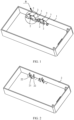
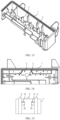
- the electronic device includes a mechanical part 1 and an antenna body 3.
- the mechanical part 1 may be a housing of an electronic product, or may be a structure, for example, a housing, a connecting rib, or a reinforcing rib of some functional components.
- the mechanical part 1 may implement mounting, protection, support, or the like of a component.
- a plurality of support ribs 2 are disposed on the mechanical part 1. Projections of the plurality of support ribs 2 in a first direction X are spaced. There is a gap H between projections of at least some of the support ribs 2 in a second direction Y The second direction Y is perpendicular to the first direction X. There may be two, three, four, or more support ribs 2. When the antenna body 3 is clamped in the gap H between the support ribs 2, two sides of the antenna may abut against each support rib 2. Stability of clamping the antenna can be ensured through support of each support rib 2.
- the support ribs 2 are disposed on the mechanical part 1, without designing a separate dedicated support for mounting the antenna body 3.
- the antenna body 3 is mounted in the gap H between the support ribs 2, to implement reliable fastening of the antenna body 3. This saves space in the electronic device, reduces a weight of the electronic device, facilitates mounting of the antenna body 3, and facilitates operations.
- the mechanical part 1 of the electronic product is generally in an irregular shape and has a complex structure, and it is inconvenient to hot melt the antenna body 3 to a structure by using a mold. Even if the mold can be used to implement a hot-melt connection between the antenna body 3 and the mechanical part 1, the mold may be interfered, or even demolding cannot be implemented because the mechanical part 1 has the complex structure, for example, has a plurality of structural ribs and spacers.
- the projections of the support ribs 2 in the first direction X are spaced, to implement normal demolding after hot melting with a mold without changing an existing structure of the mold.
- the antenna body 3 and the mechanical part 1 can be connected by using the hot melting process, to ensure reliability of a connection between the antenna body 3 and the mechanical part 1.
- the support ribs 2 can locate different positions on the antenna body 3, to ensure reliability of fastening the antenna body 3 to the mechanical part 1.
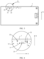
- the plurality of support ribs 2 include at least one first support rib 21 and a plurality of second support ribs 22.
- the first support rib 21 and the second support ribs 22 are respectively located on two opposite sides of the antenna body 3.
- a projection of the at least one first support rib 21 is located between projections of two adjacent second support ribs 22.
- projections of the first support rib 21 and the second support ribs 22 in the first direction X are alternately spaced.
- a projection of one first support rib 21 is adjacent to a projection of one second support rib 22.
- projections of the first support ribs 21 and the second support ribs 22 are alternately arranged, so that the antenna body 3 can be uniformly stressed, and adverse deformation caused because the antenna body 3 is non-uniformly stressed can be avoided.
- first support rib 21 when there are three support ribs 2, for example, there is one first support rib 21 and two second support ribs 22, projections of the three support ribs 2 are spaced from each other in the first direction X.
- the first support rib 21 may be located on one side of the antenna body 3.
- the two second support ribs 22 may be located on the other side of the antenna body 3.
- the projection of the separate first support rib 21 that is located on the side of the antenna body 3 is located between the projections of the two second support ribs 22 that are located on the other side of the antenna. In this way, the antenna body 3 can be uniformly stressed, and the antenna body 3 is prevented from generating adverse deformation when being non-uniformly stressed.
- projections of the four or more support ribs 2 are spaced from each other in the first direction X.
- An example in which there are four support ribs 2 is used for description.
- projections of the two first support ribs 21 and the two second support ribs 22 may be uniformly and alternately distributed, or projections of the two first support ribs 21 may be jointly located between projections of the two adjacent second support ribs 22.
- the projections of the support ribs 2 in the first direction X can be spaced, and a plurality of positions of the antenna body 3 can be supported and located. This ensures reliability of mounting the antenna body 3 on the mechanical part 1.
- the antenna body 3 includes an upright portion 31.
- the upright portion 31 is a flat plate structure.
- a thickness throughout the upright portion 31 having the flat plate structure is uniform and consistent. There may be a uniform gap H between the support ribs 2 in the first direction X, so that the upright portion 31 can be clamped into the gap H, and stability of clamping the upright portion 31 can be ensured.
- the upright portion 31 with the flat plate structure is in a regular shape for ease of processing and production and ease of assembling on the mechanical part 1.
- the upright portion 31 may be a thin metal sheet.
- the metal sheet may be made of steel, copper, silver, or the like.
- a thickness of the metal sheet may be 0.4 mm, 0.5 mm, 0.6 mm, or the like, or the metal sheet may have another thickness size, which may be specifically determined based on antenna performance.
- the non-uniform gap may be disposed between the support ribs 2 to implement reliable fastening of the antenna body 3.
- a uniform gap may be understood as an approximately uniform gap. A specific error produced in a production or assembling process is allowed.
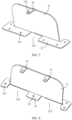
- the antenna body 3 is not necessarily a flat plate structure. Consequently, in another embodiment, as shown in FIG. 9 , the antenna body 3 includes an upright portion 31. A bent structure 34 that is bent in the first direction X is disposed on the upright portion 31. Some of the support ribs 2 are disposed on a side of the bent structure 34.
- the bent structure 34 may be but is not limited to be in a U shape, a V shape, a W shape, or the like.
- the bent structure 34 may be bent toward any side of the antenna body 3 in the first direction X.
- the bent structure 34 may be bent, in the first direction X, toward a side or a side that is opposite to the side of the upright portion 31.
- bending directions of the bent structures 34 may be the same, or may be partially different.
- at least one support rib 2 may be disposed on one side or two sides of the bent structure 34.
- the bent structure 34 may be supported by the support rib 2, to ensure a form of the bent structure.
- projections of the support rib 2 located at the bent structure 34 and another support rib 2 in the first direction X are spaced. This can facilitate demolding, and implement connection and fastening between each position of the antenna body 3 and the mechanical part 1 by using a hot melting process.
- the support rib 2 may further be disposed on one side or two sides of some positions of the bent structure 34.
- the gap H' may be used to mount the antenna body 3, to improve reliability of fastening the antenna body 3.
- Sizes such as a bending depth, a radian, and an opening width of the bent structure may be determined based on a size of a structure that needs to be avoided or radiation performance of the antenna. This is not limited in embodiments of this application.
- the antenna body 3 further includes a connecting portion 32.
- the connecting portion 32 is connected to the upright portion 31.
- the upright portion 31 is fastened to the mechanical part 1 through the connecting portion 32.
- the antenna body 3 may be fixedly connected to the entire mechanical part 1 through the connecting portion 32. This can ensure reliability of the connection and fastening between the antenna body 3 and the mechanical part 1.
- the antenna body 3 may be an integrally formed structure.
- the upright portion 31 and the connecting portion 32 may be integrally formed. This can facilitate processing and production, and can also improve structural reliability of the antenna body 3.
- the upright portion 31 and the connecting portion 32 may be perpendicularly connected to each other.
- the connecting portion 32 may be a metal sheet. The metal sheet has a large area. In this way, there is a large contact area between the connecting portion 32 and the mechanical part 1, to ensure stability of the antenna body 3.
- the connecting portion 32 may be fastened to the mechanical part 1 in a manner of the hot-melt connection, a riveted connection, or a threaded connection. Regardless of which fastening manner is used, the connecting portion 32 can be fastened to the mechanical part 1 in a height direction of the antenna body 3.
- a rivet may pass through the connecting portion 32 in the height direction of the antenna body 3 and then be fastened to the mechanical part 1.
- a specified position of the connecting portion 32 or the mechanical part 1 may be hot melt in the height direction of the antenna body 3 by using a hot-melting mold. In this way, the connecting portion 32 is fastened to the mechanical part 1 in the height direction of the antenna body 3, which may facilitate operations, and may also facilitate demolding when a hot melting process is used.
- the connecting portion 32 is provided with a second location hole 321.
- the mechanical part 1 is provided with a second hot-melt pole 12.
- the second hot-melt pole 12 passes through the second location hole 321.
- the antenna body 3 is connected to the mechanical part 1 through hot melting and fitting between the second hot-melt pole 12 and the second location hole 321.
- the second location hole 321 of the connecting portion 32 may be pre-sleeved on the second hot-melt pole 12 to implement pre-locating, and then a part that passes through and exceeds the second location hole 321 on the second hot-melt pole 12 may be hot melt by using the hot-melting mold, to implement a fixed connection between the connecting portion 32 and the mechanical part 1.
- the second location hole 321 fits the second hot-melt pole 12, to ensure position accuracy of the connecting portion 32 and the mechanical part 1.
- an avoidance notch 322 is disposed on the connecting portion 32.
- the support rib 2 is disposed in the avoidance notch 322.
- the support ribs 2 may be a part of the mechanical part 1.
- a layout of the support ribs 2 is determined. If this design is used, the support ribs 2 cannot move and change. In this case, the antenna body 3 can be mounted in the gap H only in a height direction of the support rib 2. Therefore, to avoid interference between the antenna body 3 and the support ribs 2 in a mounting process, the avoidance notch 322 may be disposed on the connecting portion 32.
- the avoidance notch 322 may be aligned with a position of a corresponding support rib 2. Then, the upright portion 31 of the antenna body 3 may be clamped into the gap H. Finally, the connecting portion 32 can abut against the mechanical part 1. This facilitates subsequent fastening operations.
- a limiting protrusion 11 is disposed on the mechanical part 1.
- the limiting protrusion 11 is disposed in the avoidance notch 322.
- the limiting protrusion 11 abuts against a side wall of the avoidance notch 322.
- the second direction Y is perpendicular to the first direction X.
- the limiting protrusion 11 on the mechanical part 1 may be in contact with the side wall of the avoidance notch 322 in the second direction Y This can limit movement of the antenna body 3 in the second direction Y by using the limiting protrusion 11, thereby ensuring reliability of the connection and fastening between the antenna body 3 and the mechanical part 1.
- movement of the antenna body 3 in the first direction X can be limited through cooperation between the support ribs 2, movement of the antenna body 3 in the second direction Y can be limited by using the limiting protrusion 11, and movement of the antenna body 3 in the height direction can be limited by fastening the connecting portion 32 to the mechanical part 1 through the hot-melt connection, the riveted connection, or the threaded connection, to ensure reliability of the connection between the antenna and the mechanical part 1.
- the at least some of the support ribs 2 include a first stiffener 23 and a second stiffener 24.
- An end of the first stiffener 23 is fixedly connected to an end of the second stiffener 24.
- a slot 25 for clamping the antenna body 3 is provided between the first stiffener 23 and the second stiffener 24.
- the antenna body 3 When the antenna body 3 is mounted, the antenna body 3 can be clamped in the gap H between the stiffeners distributed in the first direction X, and may be further clamped in the slot 25 between the first stiffener 23 and the second stiffener 24.
- the first stiffener 23 and the second stiffener 24 are respectively located on the two sides of the antenna body 3, so that the antenna body 3 is limited in the first direction X from the two sides of the antenna body 3, to further ensure reliability of the connection between the antenna body 3 and the mechanical part 1.
- a height of the first stiffener 23 is set to be less than a height of the second stiffener 24.
- the height of the first stiffener 23 is enabled to be less than the height of the second stiffener 24. This facilitates demolding, and can implement the fixed connection between the antenna body 3 and the mechanical part 1 by using the hot melting process.
- the support rib 2 formed by the first stiffener 23 and the second stiffener 24 may be integrally formed when the mechanical part 1 is produced.
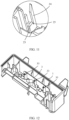
- At least one feeding part 33 is disposed on the antenna body 3.
- the feeding part 33 is bent in the first direction X and toward a side of the antenna body 3.
- the feeding part 33 is supported by the support rib 2.
- the feeding part 33 may be connected to a circuit board through a spring, for example, a printed circuit board (Printed Circuit Board, PCB).
- the feeding part 33 and the PCB may extrude the spring, to ensure reliable contact between the feeding part 33 and the PCB.
- the spring also generates reaction force on the feeding part 33, and consequently the feeding part 33 is deformed to some extent.
- the feeding part 33 is irreversibly deformed after long-term use. As a result, the feeding part 33 cannot effectively extrude the spring, and the antenna body 3 is in poor contact with the PCB.
- the support rib 2 and the PCB may be respectively located on two sides of the feeding part 33. In other words, a side that is of the feeding part 33 and backs onto the support rib 2 can abut against the PCB by using the spring, and a side that is of the feeding part 33 and that backs onto the PCB may be supported by the support rib 2, to prevent the feeding part 33 from being deformed due to extrusion of the spring. In this way, a service life of the feeding part 33 can be prolonged.
- a quantity of the feeding parts 33 is set based on an actual requirement. As shown in FIG. 7 , there may be only one feeding part 33. As shown in FIG. 8 , there may be two feeding parts 33. As shown in FIG. 12 to FIG. 14 , there may be three feeding parts 33.
- the height of the supporting rib 2 is greater than or equal to the height of the antenna body 3. In this way, a contact area between the support rib 2 and the antenna body 3 in the height direction can be maximized, and an effect of limiting and supporting the antenna body 3 is enhanced.
- the height of the support rib 2 may alternatively be slightly less than the height of the antenna body 3. In this case, stable support for the antenna can also be ensured.
- the height of the support rib 2 may be approximately equal to the height of the antenna body 3, to ensure stable support for the antenna body 3.
- heights of the support ribs 2 may be equal.
- the heights of the support ribs 2 at the different positions may be approximately equal to the heights of the corresponding positions on the antenna body 3. This can ensure reliable support for the antenna body 3 with the different heights.
- the heights of some or all of the support ribs 2 may be different, which may be specifically determined based on the heights of positions that need to be fastened and that are on the antenna body 3.
- the heights of the support ribs 2 are equal, so that force on the antenna body 3 from the support ribs 2 is uniform and consistent. This avoids a problem that the antenna body 3 is deflected and deformed due to excessively large or excessively small force on the antenna body 3 from a support rib 2. For example, if a height of the support rib 2 on one side of the antenna body 3 is less than a height of the support rib 2 on the other side of the antenna body 3, the support rib 2 with the larger height bends the antenna body 3 toward a direction in which the support rib 2 with the smaller height is located. Consequently, the antenna body 3 is deformed. When heights of the support ribs 2 on the two sides of the antenna body 3 are consistent, the two sides of the antenna body 3 are stressed uniformly, without causing a problem that the antenna body is bent toward a side is avoided.
- the height of the support rib 2 is equal to the height of the antenna body 3, and the feeding part 33 is connected to the top of the support rib 2.
- the feeding part 33 may be spliced to the top of a corresponding support rib 2, so that the feeding part 33 can be supported by the support rib 2.
- a boss 26 is disposed on a side wall of the support rib 2.
- the feeding part 33 is connected to the boss 26.
- the boss 26 may be located at a position of the support rib 2 in the height direction.
- the feeding part 33 may not be in contact with the top of the support rib 2, but may be in contact with the boss 26 on the support rib 2.
- the feeding part 33 can also be supported by the boss 26.
- a projection of the boss 26 on the support rib 2 in the first direction X and a projection of the another support rib 2 and the boss 26 thereon in the first direction X are spaced, to facilitate normal demolding.
- the feeding part 33 is fastened to the support rib 2 through a hot-melt connection, a riveted connection, or a threaded connection. This ensures reliability of a connection between the feeding part 33 and the support rib 2, and ensures that the support rib 2 effectively supports the feeding part 33.
- a first hot-melt pole 27 is disposed on the support rib 2.
- the feeding part 33 is provided with a first location hole 331 through which the first hot-melt pole 27 passes.
- the support rib 2 and the feeding part 33 are connected through hot melting and fitting between the first hot-melt pole 27 and the first location hole 331.
- the first location hole 331 on the feeding part 33 may be pre-sleeved on the first hot-melt pole 27, to pre-locate the feeding part 33. Then, a position that is on the first hot-melt pole 27 and that passes through the first location hole 331 may be hot melt by using a mold, to implement hot-melt fastening between the feeding part 33 and the support rib 2. In this way, the first location hole 331 fits the first hot-melt pole 27 to ensure position accuracy of fitting between the feeding part 33 and the support rib 2.
- each support rib 2 may be integrally formed when the mechanical part 1 is produced, to ensure reliability of an entire structure.
- a width size of the gap H formed between the support ribs 2 may be greater than or equal to a thickness size of the antenna body 3.
- the antenna body 3 can be easily clamped into the gap H, to facilitate mounting of the antenna body 3, and ensure reliability of clamping the antenna body 3.
- a material of the support rib 2 may be but is not limited to plastic, glass, ceramic, or the like.
- the plastic is preferably used.
- the plastic can facilitate processing and production, and has low costs.
- the plastic helps implement a light weight of the electronic device.
Landscapes
- Support Of Aerials (AREA)
- Arrangement Of Elements, Cooling, Sealing, Or The Like Of Lighting Devices (AREA)
Applications Claiming Priority (2)
| Application Number | Priority Date | Filing Date | Title |
|---|---|---|---|
| CN202211383948.0A CN117996399A (zh) | 2022-11-07 | 2022-11-07 | 电子设备 |
| PCT/CN2023/126378 WO2024099072A1 (zh) | 2022-11-07 | 2023-10-25 | 电子设备 |
Publications (2)
| Publication Number | Publication Date |
|---|---|
| EP4407794A1 true EP4407794A1 (de) | 2024-07-31 |
| EP4407794A4 EP4407794A4 (de) | 2025-03-05 |
Family
ID=90898168
Family Applications (1)
| Application Number | Title | Priority Date | Filing Date |
|---|---|---|---|
| EP23878390.6A Pending EP4407794A4 (de) | 2022-11-07 | 2023-10-25 | Elektronische vorrichtung |
Country Status (4)
| Country | Link |
|---|---|
| EP (1) | EP4407794A4 (de) |
| JP (1) | JP7758276B2 (de) |
| CN (1) | CN117996399A (de) |
| WO (1) | WO2024099072A1 (de) |
Family Cites Families (14)
| Publication number | Priority date | Publication date | Assignee | Title |
|---|---|---|---|---|
| JP2006025041A (ja) * | 2004-07-06 | 2006-01-26 | Matsushita Electric Ind Co Ltd | アンテナ内蔵電子装置 |
| JP2007189612A (ja) * | 2006-01-16 | 2007-07-26 | Nec Tokin Corp | Rfidアンテナ |
| US7425925B2 (en) * | 2006-02-27 | 2008-09-16 | Nissan Technical Center North America, Inc. | Vehicle security system |
| JP2009135339A (ja) * | 2007-11-30 | 2009-06-18 | Mitsumi Electric Co Ltd | ケーブルの固定構造及び電子機器 |
| KR101047816B1 (ko) * | 2009-09-18 | 2011-07-08 | 임미숙 | 휴대 단말기용 인테나 |
| KR100982028B1 (ko) * | 2009-11-30 | 2010-09-14 | 주식회사 네오펄스 | 수직 방사체를 가진 내장형 안테나 및 그 제조방법 |
| CN101867629A (zh) * | 2010-06-04 | 2010-10-20 | 惠州Tcl移动通信有限公司 | 一种内置天线的手机装置及其生产方法 |
| KR101333114B1 (ko) * | 2011-10-20 | 2013-11-26 | 삼성전자주식회사 | 휴대용 단말기를 위한 와이어 타입 내장형 안테나 장치 및 이의 제조 방법 |
| CN202817170U (zh) * | 2012-10-15 | 2013-03-20 | 上海华勤通讯技术有限公司 | 具有蓝牙天线的移动终端 |
| WO2014136243A1 (ja) * | 2013-03-07 | 2014-09-12 | 株式会社 東芝 | テレビジョン受像機、及び電子機器 |
| CN207459152U (zh) * | 2017-11-20 | 2018-06-05 | 上海斐讯数据通信技术有限公司 | 一种pcb天线的固定结构 |
| CN208596777U (zh) * | 2018-09-06 | 2019-03-12 | 歌尔科技有限公司 | 一种天线装置及外置网卡 |
| CN209523966U (zh) * | 2019-01-25 | 2019-10-22 | 武汉虹信通信技术有限责任公司 | 卡扣连接件及基站天线 |
| CN216597957U (zh) * | 2022-01-13 | 2022-05-24 | 深圳市金溢科技股份有限公司 | 天线引导板固定结构及车载单元 |
-
2022
- 2022-11-07 CN CN202211383948.0A patent/CN117996399A/zh active Pending
-
2023
- 2023-10-25 JP JP2024526797A patent/JP7758276B2/ja active Active
- 2023-10-25 WO PCT/CN2023/126378 patent/WO2024099072A1/zh not_active Ceased
- 2023-10-25 EP EP23878390.6A patent/EP4407794A4/de active Pending
Also Published As
| Publication number | Publication date |
|---|---|
| JP2024544127A (ja) | 2024-11-28 |
| JP7758276B2 (ja) | 2025-10-22 |
| WO2024099072A1 (zh) | 2024-05-16 |
| CN117996399A (zh) | 2024-05-07 |
| EP4407794A4 (de) | 2025-03-05 |
Similar Documents
| Publication | Publication Date | Title |
|---|---|---|
| US10306032B2 (en) | Bracket assembly, camera module, and mobile terminal | |
| EP2605629A2 (de) | Abschirmungssystem für eine mobile Vorrichtung und Verfahren zu Montage des Systems | |
| CN109903681B (zh) | 支撑结构及其制造方法、显示装置及其装配方法 | |
| EP4213067A1 (de) | Elektronische vorrichtung | |
| JP6045953B2 (ja) | コネクタ | |
| CN110191213A (zh) | 移动终端 | |
| CN110277702A (zh) | 电子设备 | |
| EP4391505A1 (de) | Endgerätevorrichtung | |
| EP4391506B1 (de) | Elastisches erdungsteil und elektronische vorrichtung | |
| EP4407794A1 (de) | Elektronische vorrichtung | |
| CN112153845B (zh) | 电子设备及其电路模组 | |
| JP2006179451A (ja) | 無接地型電気コネクタ | |
| JP6960996B2 (ja) | 電子デバイス | |
| CN115086461B (zh) | 一种电子设备 | |
| CN107611571B (zh) | 弹性件、功能组件及移动终端 | |
| US7578677B2 (en) | Shielded shell having a spring finger integrally formed therewith | |
| US9733675B2 (en) | Elastic body and electronic device | |
| US20200099129A1 (en) | Chassis for electronic device and electronic device | |
| US20250008648A1 (en) | Pin structure of module power supply, and module power supply | |
| CN207082665U (zh) | Pos机充电结构 | |
| CN210984973U (zh) | 具有止高基座及侧突悬臂的表面安装减偏弹片 | |
| CN222602886U (zh) | 屏蔽罩和显示装置 | |
| CN212970245U (zh) | 一种电子设备用补强零件 | |
| CN110582177B (zh) | 电路板固定组件及电子设备 | |
| CN212064653U (zh) | 固定装置及固定板 |
Legal Events
| Date | Code | Title | Description |
|---|---|---|---|
| STAA | Information on the status of an ep patent application or granted ep patent |
Free format text: STATUS: UNKNOWN |
|
| STAA | Information on the status of an ep patent application or granted ep patent |
Free format text: STATUS: THE INTERNATIONAL PUBLICATION HAS BEEN MADE |
|
| PUAI | Public reference made under article 153(3) epc to a published international application that has entered the european phase |
Free format text: ORIGINAL CODE: 0009012 |
|
| STAA | Information on the status of an ep patent application or granted ep patent |
Free format text: STATUS: REQUEST FOR EXAMINATION WAS MADE |
|
| 17P | Request for examination filed |
Effective date: 20240429 |
|
| AK | Designated contracting states |
Kind code of ref document: A1 Designated state(s): AL AT BE BG CH CY CZ DE DK EE ES FI FR GB GR HR HU IE IS IT LI LT LU LV MC ME MK MT NL NO PL PT RO RS SE SI SK SM TR |
|
| REG | Reference to a national code |
Ref country code: DE Ref legal event code: R079 Free format text: PREVIOUS MAIN CLASS: H01Q0001220000 Ipc: H01Q0001120000 |
|
| A4 | Supplementary search report drawn up and despatched |
Effective date: 20250204 |
|
| RIC1 | Information provided on ipc code assigned before grant |
Ipc: H01Q 1/32 20060101ALI20250129BHEP Ipc: H01Q 1/12 20060101AFI20250129BHEP |
|
| DAV | Request for validation of the european patent (deleted) | ||
| DAX | Request for extension of the european patent (deleted) |