EP4405526B1 - Vorrichtung zum positionieren von gleisbearbeitungsgeräten am gleis - Google Patents
Vorrichtung zum positionieren von gleisbearbeitungsgeräten am gleis Download PDFInfo
- Publication number
- EP4405526B1 EP4405526B1 EP22772867.2A EP22772867A EP4405526B1 EP 4405526 B1 EP4405526 B1 EP 4405526B1 EP 22772867 A EP22772867 A EP 22772867A EP 4405526 B1 EP4405526 B1 EP 4405526B1
- Authority
- EP
- European Patent Office
- Prior art keywords
- track
- transverse positioning
- positioning device
- transverse
- support
- Prior art date
- Legal status (The legal status is an assumption and is not a legal conclusion. Google has not performed a legal analysis and makes no representation as to the accuracy of the status listed.)
- Active
Links
Images






Classifications
-
- E—FIXED CONSTRUCTIONS
- E01—CONSTRUCTION OF ROADS, RAILWAYS, OR BRIDGES
- E01B—PERMANENT WAY; PERMANENT-WAY TOOLS; MACHINES FOR MAKING RAILWAYS OF ALL KINDS
- E01B27/00—Placing, renewing, working, cleaning, or taking-up the ballast, with or without concurrent work on the track; Devices therefor; Packing sleepers
- E01B27/12—Packing sleepers, with or without concurrent work on the track; Compacting track-carrying ballast
- E01B27/13—Packing sleepers, with or without concurrent work on the track
- E01B27/16—Sleeper-tamping machines
-
- E—FIXED CONSTRUCTIONS
- E01—CONSTRUCTION OF ROADS, RAILWAYS, OR BRIDGES
- E01B—PERMANENT WAY; PERMANENT-WAY TOOLS; MACHINES FOR MAKING RAILWAYS OF ALL KINDS
- E01B27/00—Placing, renewing, working, cleaning, or taking-up the ballast, with or without concurrent work on the track; Devices therefor; Packing sleepers
- E01B27/12—Packing sleepers, with or without concurrent work on the track; Compacting track-carrying ballast
- E01B27/13—Packing sleepers, with or without concurrent work on the track
- E01B27/16—Sleeper-tamping machines
- E01B27/17—Sleeper-tamping machines combined with means for lifting, levelling or slewing the track
-
- E—FIXED CONSTRUCTIONS
- E01—CONSTRUCTION OF ROADS, RAILWAYS, OR BRIDGES
- E01B—PERMANENT WAY; PERMANENT-WAY TOOLS; MACHINES FOR MAKING RAILWAYS OF ALL KINDS
- E01B29/00—Laying, rebuilding, or taking-up tracks; Tools or machines therefor
- E01B29/24—Fixing or removing detachable fastening means or accessories thereof; Pre-assembling track components by detachable fastening means
- E01B29/28—Fixing or removing detachable fastening means or accessories thereof; Pre-assembling track components by detachable fastening means the fastening means being of screw-and-nut type; Apparatus therefor, adapted to additionally drilling holes
-
- E—FIXED CONSTRUCTIONS
- E01—CONSTRUCTION OF ROADS, RAILWAYS, OR BRIDGES
- E01B—PERMANENT WAY; PERMANENT-WAY TOOLS; MACHINES FOR MAKING RAILWAYS OF ALL KINDS
- E01B2203/00—Devices for working the railway-superstructure
- E01B2203/12—Tamping devices
- E01B2203/122—Tamping devices for straight track
-
- E—FIXED CONSTRUCTIONS
- E01—CONSTRUCTION OF ROADS, RAILWAYS, OR BRIDGES
- E01B—PERMANENT WAY; PERMANENT-WAY TOOLS; MACHINES FOR MAKING RAILWAYS OF ALL KINDS
- E01B2203/00—Devices for working the railway-superstructure
- E01B2203/12—Tamping devices
- E01B2203/125—Tamping devices adapted for switches or crossings
-
- E—FIXED CONSTRUCTIONS
- E01—CONSTRUCTION OF ROADS, RAILWAYS, OR BRIDGES
- E01B—PERMANENT WAY; PERMANENT-WAY TOOLS; MACHINES FOR MAKING RAILWAYS OF ALL KINDS
- E01B31/00—Working rails, sleepers, baseplates, or the like, in or on the line; Machines, tools, or auxiliary devices specially designed therefor
- E01B31/02—Working rail or other metal track components on the spot
- E01B31/12—Removing metal from rails, rail joints, or baseplates, e.g. for deburring welds, reconditioning worn rails
- E01B31/17—Removing metal from rails, rail joints, or baseplates, e.g. for deburring welds, reconditioning worn rails by grinding
-
- E—FIXED CONSTRUCTIONS
- E01—CONSTRUCTION OF ROADS, RAILWAYS, OR BRIDGES
- E01B—PERMANENT WAY; PERMANENT-WAY TOOLS; MACHINES FOR MAKING RAILWAYS OF ALL KINDS
- E01B31/00—Working rails, sleepers, baseplates, or the like, in or on the line; Machines, tools, or auxiliary devices specially designed therefor
- E01B31/02—Working rail or other metal track components on the spot
- E01B31/18—Reconditioning or repairing worn or damaged parts on the spot, e.g. applying inlays, building-up rails by welding; Heating or cooling of parts on the spot, e.g. for reducing joint gaps, for hardening rails
Definitions
- the invention relates to a device for positioning track maintenance equipment on the track. Furthermore, the invention relates to a track maintenance system with such a device.
- the device comprises two support modules with equipment carriers for supporting the track maintenance equipment and a rotating device for rotating the two support modules around a vertical axis of rotation.
- the design of the device limits the ability of the track maintenance equipment to move relative to the track. This has correspondingly limiting effects on their area of application and the cost-effectiveness of track maintenance.
- Devices for positioning track maintenance equipment on the track are also known from DE 4001488 A1 , the DE 2023964 B2 and the DE 4313300 A1 .
- a device for positioning track maintenance equipment on the track with at least two support modules and a rotating device for the rotational displacement of the at least two support modules can be used particularly flexibly and economically in Operation is when the rotating device has at least two rotating units for the independent rotational displacement of the at least two support modules.
- the at least two rotating units can be rotated independently of one another relative to one another and/or relative to the track by means of the rotating device.
- the rotating device is preferably designed for the rotational displacement of the at least two support modules about a respective rotational axis.
- the rotational axes are preferably oriented parallel, in particular vertically. The rotational axes can be arranged at a distance from one another.
- the at least two support modules can be rotationally displaced about the same rotational axis. Because the support modules can be rotated independently of one another, the at least one track maintenance device can be positioned particularly flexibly on the track. In particular, the device carriers of the at least two support modules can be aligned independently of one another according to an orientation that is particularly conducive to the processing of the track. As a result, the processing devices can be positioned flexibly on the track, whereby track maintenance, in particular in the area of switches, can be carried out particularly time-efficiently and economically.
- the first transverse positioning device is preferably designed for the linear displacement of the at least two support modules along a first transverse positioning direction.
- the displacement of the at least two support modules by means of the first transverse positioning device preferably takes place for all support modules along the same, in particular in the same, first transverse positioning direction.
- the at least two support modules can be displaced in different transverse positioning directions. Between the different transverse positioning directions there is preferably an angle in a range from 0° to 90°, in particular from 1° to 75°, in particular from 5° to 45°, in particular from 10° to 30°, in particular from 15° to 20°.
- the first transverse positioning direction is oriented obliquely to the track, specifically at an angle, in particular an acute angle, of at least 30°, in particular at least 45°, in particular at least 60°, in particular at least 75°, in particular at least 85°, in particular perpendicular, to the longitudinal direction of the track.
- An acute angle is a maximum of 90°, in particular less than 90°.
- the at least two support modules can preferably be displaced by means of the first transverse positioning device over a travel range in the range from 30 cm to 150 cm, in particular from 50 cm to 100 cm.
- the first transverse positioning device is preferably connected to a carriage for traveling on rails, in particular to a carriage support, in a rotationally fixed manner, in particular about a vertical direction and/or about a longitudinal rail direction and/or about a transverse rail direction, and/or translationally fixed, in particular in the vertical direction and/or in the longitudinal rail direction and/or in the transverse rail direction.
- the first transverse positioning device can be rotationally and/or translationally rigidly connected to the carriage, in particular to the carriage support. This allows the positioning of the track maintenance devices to be particularly precise.
- the linear displacement of an object is preferably understood to mean a purely translational displacement of the object, in particular along a straight line.
- a linear guide and/or a linear drive can be provided for the linear displacement of the object.
- the linear drive is preferably a hydraulic drive, in particular a hydraulic cylinder.
- the rotating units are preferably designed for rotational displacement, in particular for pivoting the respective support modules, over an angular range of at least ⁇ 5°, in particular at least ⁇ 7°, in particular at least ⁇ 10°, in particular at least ⁇ 20°, in particular at least ⁇ 45°, in particular at least ⁇ 90°, and/or a maximum of ⁇ 180°, in particular a maximum of ⁇ 90°, in particular a maximum of ⁇ 45°, in particular a maximum of ⁇ 20°.
- the horizontal positioning device can preferably be oriented by means of the respective rotating unit such that the displacement of the at least one equipment carrier can take place in a direction oblique, in particular perpendicular, to a longitudinal direction of the track.
- the aforementioned angular ranges are preferably dimensioned starting from a neutral position in which the horizontal positioning device can displace the at least one equipment carrier in a direction perpendicular to the longitudinal direction of the track. This allows the equipment carriers to be aligned particularly flexibly and precisely along the track.
- the horizontal direction is understood to mean a direction which has an angle of maximum 25°, in particular maximum 10°, in particular maximum 5°, in particular maximum 2°, to the horizontal plane.
- the horizontal positioning device is preferably designed such that it ensures the displacement of the at least one device carrier over a travel range in the range of 30 cm to 120 cm, in particular from 50 cm to 100 cm.
- the horizontal positioning devices of the two support modules are preferably designed independently of each other, so that At least one device carrier of the respective support module can be displaced horizontally independently of the at least one device carrier of the other support module. This advantageously ensures that the device carriers can be positioned particularly flexibly on the track.
- the respective support module has at least two, in particular at least three, in particular at least four, of the device carriers.
- the respective support module comprises exactly two of the device carriers.
- Each of the device carriers is preferably designed to support at least one, in particular at least two, processing devices. This allows track processing to be carried out particularly efficiently and economically.
- At least one, in particular all, equipment carriers have a vertical positioning device for linearly displacing the track maintenance equipment, in particular substantially in the vertical direction.
- the vertical positioning device can be configured to immerse the track maintenance equipment, in particular the tamping tines of a tamping unit, into a ballast bed of the track.
- vertical direction preferably also includes directions that are not exactly but essentially vertically oriented, in particular having an angle to a vertically oriented axis of a maximum of 15°, in particular a maximum of 10°, in particular a maximum of 5°, in particular a maximum of 2°, in particular a maximum of 1°.
- the rotating device in particular a rotary bearing and/or a rotary drive, overlaps the horizontal positioning device, in particular a horizontal guide and/or a horizontal positioning drive, at least in sections in a horizontal direction. This allows a particularly low overall height of the device to be achieved.
- An overlap in and/or along a specific direction is understood to mean an overlap that exists in an orthogonal projection onto a projection plane that is oriented perpendicular to the specific direction.
- the device comprises at least two, in particular at least three, in particular at least four, of the support modules.
- the device comprises exactly two of the support modules.
- the device preferably comprises a connecting means for fastening the device, in particular to a rail vehicle.
- the connecting means is preferably designed to create a reversibly detachable connection.
- the connecting means can be designed to form a frictional connection, in particular a screw connection, and/or a positive connection.
- the device comprises a longitudinal positioning device for linearly displacing the at least two support modules, in particular substantially parallel to a rail longitudinal direction.
- the first transverse positioning device is arranged on the Longitudinal positioning device is attached so that the first transverse positioning device can be linearly displaced along the longitudinal direction of the rail.
- the parallel orientation of two directions to each other also includes orientations of two directions to each other between which there is an angle of a maximum of 15°, in particular a maximum of 10°, in particular a maximum of 5°, in particular a maximum of 2°, in particular a maximum of 1°.
- the longitudinal positioning device is preferably connected to the carriage for traveling on rails, in particular to the carriage support, in a rotationally fixed manner, in particular about a vertical direction and/or a longitudinal rail direction and/or a transverse rail direction, and/or translationally fixed, in particular in the vertical direction and/or in the longitudinal rail direction and/or in the transverse rail direction.
- the longitudinal positioning device can be completely rigidly connected to the carriage, in particular to the carriage support. This allows the positioning of the track maintenance equipment to be particularly precise.
- a device enables the positioning of the at least two track maintenance devices in a particularly flexible manner.
- the two support modules are preferably linearly displaceable relative to each other and/or to the track by means of the first transverse positioning device.
- the first transverse positioning device preferably comprises a transverse positioning support to which the at least two transverse positioning units are mounted in a linearly displaceable manner.
- the first transverse positioning device preferably comprises a telescopic guide. The device can thus be arranged in a particular way, especially in the transverse direction, and is therefore easy to transport and flexible in use.
- a device enables the positioning of the at least two track maintenance devices in a particularly flexible manner.
- the second transverse positioning device is preferably designed for the linear displacement of the at least two support modules along a second transverse positioning direction.
- the transverse positioning directions can be oriented parallel or obliquely to one another.
- the second transverse positioning direction is preferably oriented parallel to the first transverse positioning direction, in particular perpendicular to the longitudinal direction of the track.
- the second transverse positioning direction preferably comprises a telescopic guide. This allows the second transverse positioning direction to be arranged in a particularly space-saving manner.
- the second transverse positioning direction can be designed for the displacement of the at least two support modules along a travel range in the range of 30 cm to 150 cm, in particular of 50 cm to 100 cm.
- the second transverse positioning device is preferably connected to a carriage for traveling on rails, in particular to a carriage support, in a rotationally fixed manner, in particular about a vertical direction and/or a longitudinal rail direction and/or a transverse rail direction, and/or translationally fixed, in particular in the vertical direction and/or in the longitudinal rail direction and/or in the transverse rail direction.
- the second transverse positioning device can be completely rigidly connected to the carriage, in particular to the carriage support. This allows the positioning of the track maintenance equipment to be particularly precise.
- the second transverse positioning device is attached to the longitudinal positioning device so that the second transverse positioning device is linearly displaceable along the longitudinal direction of the rail.
- the first transverse positioning device and the second transverse positioning device are preferably designed to displace the at least two support modules perpendicular to the longitudinal direction of the track. This allows for a particularly large area of the track that can be processed by the track processing devices, thus allowing the device to have a particularly wide range of applications.
- a device ensures the positioning of the at least two track maintenance devices in a particularly flexible manner.
- the at least two rotating units can be displaced synchronously with one another by means of the first transverse positioning device and/or the second transverse positioning device, in particular at a fixed distance from one another, in particular rigidly connected to one another, and/or independently of one another, in particular relative to one another and/or relative to the track.
- the first transverse positioning device and/or the second transverse positioning device are designed such that a distance between the axes of rotation of the at least two rotating units is variable.
- a device according to claim 5 is particularly user-friendly and robust in operation.
- the device is preferably designed such that the at least two support modules can be displaced synchronously by means of the second transverse positioning device. Because the first transverse positioning device is attached to the second transverse positioning device, the at least two support modules can be displaced synchronously by means of the second transverse positioning device, in particular if the first transverse positioning device has the at least two transverse positioning units, to each of which in particular one of the rotary units is attached.
- a device is particularly lightweight, can be arranged particularly compactly, and makes a particularly large processing space accessible for track processing.
- the first transverse positioning device and the second transverse positioning device overlap one another at least partially in a horizontal direction and/or in a vertical direction.
- the first transverse positioning device and the second transverse positioning device can overlap one another perpendicular to the respective transverse positioning direction, in particular over at least 30%, in particular at least 50%, of their extent along the transverse positioning direction.
- the first transverse positioning device and the second transverse positioning device can be designed to be telescopic into one another at least partially.
- the linear guides of the first transverse positioning device and the second transverse positioning device are arranged at a distance from one another in a horizontal direction, in particular perpendicular to the transverse positioning direction.
- a device according to claim 7 ensures a particularly large range for positioning the track maintenance equipment laterally along the track.
- Moving perpendicular to the track is understood to mean moving perpendicular to the longitudinal extent of the track, in particular in the horizontal direction.
- the first transverse positioning device and/or the second transverse positioning device and/or the horizontal positioning device are designed such that their travel distances for displacing the at least one device carrier are at least partially, in particular completely, added together. This allows the track maintenance devices to be displaced particularly far in the direction perpendicular to the longitudinal extent of the track.
- a device according to claim 8 has a particularly long range for positioning the track maintenance equipment laterally along the track. Such a device is particularly flexible and economical to use.
- the transverse adjustment range is preferably at least 160 cm, in particular at least 180 cm, in particular at least 200 cm, in particular at least 220 cm.
- a device according to claim 9 can be designed to be particularly lightweight and compact.
- the support device is preferably designed to support the at least one support module, which is displaced obliquely to the track by means of the first transverse positioning device and/or the second transverse positioning device, in the vertical direction and/or in the longitudinal direction of the track. Supporting is understood to mean that at least a portion of the weight force acting on the support module and/or the reaction forces acting on it during track maintenance are displaced via the support device.
- the support device preferably comprises a linear guide which is displaceable, in particular extendable, together with the first transverse positioning device and/or the second transverse positioning device.
- the support device comprises a first support part, in particular at least one support beam, and a linearly displaceable attached second support part, in particular at least one telescopic support.
- the second support part can be connected to the at least one support module, preferably reversibly.
- the support device can be controlled such that a single, freely selectable one of the support modules can be reversibly supported.
- the support device can be extended transversely, in particular perpendicular to the track, and/or in the horizontal direction.
- a device according to claim 10 is particularly safe in operation.
- the transport lock can be designed as a frictional connection, in particular as a clamping connection, and/or as a form-fitting connection, in particular as a locking connection.
- the transport lock is designed alternatively or additionally for locking the horizontal positioning device and/or the vertical positioning device.
- the transport position is preferably determined by a position of the device in which the device has the smallest dimension transverse to the longitudinal direction of the track. In the transport position, the device is preferably arranged completely within a permissible clearance profile. In the transport position, the device can be arranged for a transfer run.
- a device ensures the positioning of the track maintenance equipment on the track in a particularly flexible manner.
- the carriage can be designed as a trailer, without its own drive, or with a drive.
- the drive can be designed to move the carriage for a transfer run and/or to move the carriage during track maintenance.
- the device preferably comprises a control unit for controlling the traction drive and/or the rotating device and/or the horizontal positioning device and/or the first transverse positioning device and/or the second transverse positioning device and/or the vertical positioning device and/or the at least one track maintenance device. This advantageously allows the respective displacement movements to be coordinated with one another.
- the rotating device and/or the horizontal positioning device and/or the first transverse positioning device and/or the second transverse positioning device and/or the vertical positioning device preferably have at least one drive.
- This drive is preferably in signal communication with the control unit.
- the drive can have a fluidic actuator, in particular a piston-cylinder unit, in particular a hydraulic cylinder.
- the carriage preferably has a carriage support.
- the rotating device is preferably connected to the carriage support.
- the second transverse positioning device can be attached to the carriage support, in particular rigidly, in particular in a non-detachable and/or reversibly detachable manner.
- the at least one device carrier is attached to the horizontal positioning device.
- the horizontal positioning device can be attached to the respective support module.
- the respective support module can be attached to one of the rotating units of the rotating device.
- the rotating device is preferably attached to the first transverse positioning device.
- the first transverse positioning device can be attached to the second transverse positioning device.
- the A second transverse positioning device can be attached to the carriage carrier.
- the respective equipment carrier has the vertical positioning device.
- a further object of the invention is to provide an improved track processing system which is particularly flexible in use and economical in operation.
- the advantages of the track maintenance system correspond to the advantages of the device described above.
- the track maintenance system is preferably further developed with at least one of the features described above in connection with the device.
- the track maintenance system preferably has at least two, in particular at least three, in particular at least four, in particular at least six, in particular at least eight, of the track maintenance devices.
- the device can be designed to move the at least one track processing device into a working position which is at least 250 cm away from a vertical track center plane.
- a track processing system has a wide range of applications and is particularly economical to use.
- the vertical track center plane is preferably understood to be a plane which is oriented vertically and parallel to the longitudinal direction of the track and is arranged centrally between the rails.
- the working position can be delimited by an outer contour of an area which can be processed by the at least one processing device.
- the distance between the vertical track center plane and the outer contour of the The area that can be processed by at least one processing device is preferably at least 250 cm, in particular at least 275 cm, in particular at least 300 cm, in particular at least 325 cm, in particular 350 cm, and/or a maximum of 400 cm, in particular a maximum of 350 cm, in particular a maximum of 325 cm.
- a track maintenance system is particularly economical in operation.
- the at least one track maintenance device can be designed as a tamping unit and/or as a connecting unit, in particular as a screwing unit and/or as a welding unit, and/or as a grinding unit, in particular as a rail grinding unit, and/or as a cleaning unit.
- the track maintenance device can exclusively comprise track maintenance devices of the same type mentioned above or of different types mentioned above.
- the track maintenance system 1 comprises at least one track maintenance device 2 and a device 3 for positioning the at least one track maintenance device 2 on the track 4.
- the track maintenance devices 2 are detachably attached to the device 3.
- the device 3 is designed to carry a changing number of track maintenance devices 2, in particular at least one track maintenance device 2.
- the track processing system 1 is shown with two track processing devices 2 attached to the device 3.
- the Fig. 10 to Fig. 12 Four of the track maintenance devices 2 are attached to the device 3.
- the device 3 is designed to support and position a maximum of 8 track maintenance devices 2.
- the track maintenance devices 2 are each designed as tamping units for compacting a ballast bed 5 of the track 4.
- at least one of the track maintenance devices can be designed as a screwing unit, in particular for tightening and loosening screw connections, in particular screw connections for fastening rails 6, and/or as a welding unit, in particular for welding the rails 6, and/or as a grinding unit, in particular for grinding the rails 6, and/or as a cleaning unit, in particular for cleaning the track 4.
- the tamping units 2 each have at least two, in particular four, tamping picks 7 for reversibly penetrating the ballast bed during compaction.
- the tamping picks 7 are arranged in pairs such that they can penetrate the ballast bed 5 on both sides of a track sleeper 8 in order to convey the ballast beneath the respective track sleeper 8.
- the paired tamping picks 7 are spaced apart from one another in the longitudinal direction 9 of the rails 6.
- the longitudinal direction 9 is oriented parallel to the rails 6.
- a transverse direction 10 is oriented horizontally and perpendicularly to the longitudinal direction 9.
- a vertical direction 11 is oriented perpendicularly to the longitudinal direction 9 and to the transverse direction 10.
- the device 3 has a carriage 12 for traveling along the rails 6.
- the carriage 12 comprises two bogies 13 and is designed as a trailer without a traction drive.
- the carriage 12 can have a traction motor for driving along the rails 6.
- the carriage 12 has a carriage support 14 with a first support 15a and a second support 15b for supporting the respective bogie 13.
- the device 3 has a first transverse positioning device 16 and a second transverse positioning device 17.
- the second transverse positioning device 17 has two transverse positioning parts 18a, 18b that can be displaced linearly relative to one another.
- the second transverse positioning device 17 further comprises a transverse positioning drive 18c for linearly driving the transverse positioning parts 18a, 18b relative to one another.
- the first transverse positioning part 18a is attached, in particular rigidly, to the carriage support 14.
- the second transverse positioning part 18b is displaceable relative to the first transverse positioning part 18a along a second transverse positioning direction 18d.
- the second transverse positioning direction 18d is oriented obliquely, in particular perpendicularly, to the track 4 and horizontally, in particular parallel to the transverse direction 10.
- the first transverse positioning device 16 is attached to the second transverse positioning device 17 such that the first transverse positioning device 16 is linearly displaceable obliquely, in particular perpendicularly, to the track 4 and horizontally, in particular along the transverse direction 10.
- the first transverse positioning device 16 has two transverse positioning units 19, 20.
- the two transverse positioning units 19, 20 are identically designed.
- the first transverse positioning device 16 comprises a transverse positioning support 21 and two transverse positioning unit drives 22a, 22b.
- the transverse positioning support 21 is attached, in particular rigidly, to the second transverse positioning part 18b of the second transverse positioning device 17.
- the respective transverse positioning unit drive 22a, 22b is for displacing one of the Transverse positioning units 19, 20 are formed independently of the other transverse positioning unit 19, 20 along a first transverse positioning direction 23.
- the first transverse positioning direction 23 is oriented parallel to the second transverse positioning direction 18d and to the transverse direction 10.
- the device 3 has a rotating device 24 with two rotating units 25, 26.
- the first rotating unit 25 is attached to the first transverse positioning unit 19.
- the second rotating unit 26 is attached to the second transverse positioning unit 20.
- the rotating device 24 is connected to the first transverse positioning device 16 and the second transverse positioning device 17 such that the rotating device 24 can be displaced obliquely, in particular perpendicularly, to the track 4 and horizontally, in particular in the transverse direction 10, linearly.
- the first rotary unit 25 has two rotary parts 27a, 27b that can rotate relative to one another.
- the second rotary unit 26 has two rotary parts 28a, 28b that can rotate relative to one another.
- the two rotary units 25, 26 each have a rotary drive 27c, 28c.
- the rotary drives 27c, 28c are designed to rotate, in particular to pivot, the respective first rotary part 27a, 28a relative to the second rotary part 27b, 28b about a respective rotation axis 27d, 28d.
- the first rotary unit 25, in particular its first rotary part 27a is attached to the first transverse positioning unit 19.
- the second rotary unit 26, in particular its first rotary part 28a is attached to the second transverse positioning unit 20.
- the two axes of rotation 27d, 28d are oriented vertically, in particular parallel to the vertical direction 11.
- the device 3 has two support modules 29, 30.
- the first support module is attached to the first rotating unit 25, in particular to the second rotating part 27b. attached.
- the second support module 30 is attached to the second rotating unit 26, in particular to the second rotating part 28b.
- the support modules 29, 30 are identically designed.
- the support modules 29, 30 each comprise two equipment carriers 31a, 31b for supporting at least one track maintenance device 2 and a horizontal positioning device 32 for displacing the equipment carriers 31a, 31b in a horizontal direction 33a, 33b, 33c.
- the horizontal positioning devices 32 comprise horizontal positioning drives 34a, 34b for displacing the equipment carriers 31a, 31b along the horizontal direction 33a, 33b, 33c.
- the vertical positioning devices 35 comprise vertical positioning drives 36a, 36b for automated displacement.
- all of the above-described drives 18c, 22a, 22b, 27c, 28c, 34a, 34b, 36a, 36b are designed as fluidic drives, in particular as piston-cylinder actuators, in particular as hydraulic cylinders.
- the device 3 has a support device 37 for supporting the two support modules 29, 30 in the vertical direction 11, in particular in the longitudinal direction 9.
- the support device 37 comprises two support parts 38a, 38b that are linearly displaceable relative to one another.
- the first support part 38a is attached, in particular rigidly, to the carriage support 14.
- the second support part 38b is reversibly attachable to the first support module 29 or to the second support module 30.
- the first support part 38a comprises two support supports 39a, 39b.
- the second support part 38b comprises two telescopic supports 40a, 40b, each of which is linearly displaceably received in one of the support supports 39a, 39b.
- the device 3 has a transport lock 41a, 41b for reversibly locking the first transverse positioning device 16 and the second transverse positioning device 17 in a transport position.
- the track processing system in particular the device 3 and the track processing equipment 2, are arranged completely within a predetermined clearance profile 42 of the track 4.
- a vertical track center plane 43 is oriented parallel to the longitudinal direction 9 and the vertical direction 11 and, with respect to the transverse direction 10, runs centrally between the rails 6 and/or centrally through the device 3, in particular the device 3 arranged in the transport position.
- a distance x T1 between the vertical track center plane 43 and the first equipment carrier 31a, in particular its center point along the transverse direction 10, is 800 mm in the transport position.
- the distance x T1 is a maximum of 2600 mm in a working position.
- the first equipment carrier 31a can therefore be displaced by 1800 mm along the transverse direction 10, in particular by means of the transverse positioning devices 16, 17 and the horizontal positioning device 32.
- the distance x T2 between the vertical track center plane 43 and the second equipment carrier 31b is 650 mm.
- the second equipment carrier 31b is also displaceable by 1800 mm along the transverse direction 10.
- a distance x P between the vertical track center plane 43 and an outer contour of the area of the ballast bed 5 that can be worked by the tamping picks 7 is 1300 mm in the transport position. In a working position, this distance x P is a maximum of 3100 mm.
- the rotating device 24 and the first transverse positioning device 16 and/or the second transverse positioning device 17 and/or the horizontal positioning device 32 overlap each other at least partially in a horizontal direction. This allows a particularly low overall height H of the device 3 to be achieved.
- the operation of the track processing system 1, in particular the device 3, is as follows:
- the carriage 12 is arranged on the track 4.
- the track tamping units 2 are attached to the equipment carriers 31a, 31b, in particular to the respective vertical positioning device 35.
- the equipment carriers 31a, 31b are attached to the horizontal positioning device 32 of the respective support module 29, 30.
- the support modules 29, 30 are each attached to one of the rotating units 25, 26 of the rotating device 24.
- the rotating units 25, 26 are each attached to one of the transverse positioning units 19, 20 of the first transverse positioning device 16.
- the first transverse positioning device 16 is attached to the second transverse positioning device 17, which is fastened to the carriage carrier 14 of the carriage 12.
- the device 3 is in the transport position, i.e., completely within the clearance profile 42.
- the track processing system 1, in particular the device 3, is in particular in the Fig. 10 shown in the transport position.
- the transverse positioning devices 16, 17 are locked in the transport position by means of the transport lock 41a, 41b.
- the carriage 12 is transported to the section of track 4 to be processed.
- the transport lock 41a, 41b is released, and the track processing devices 2 are arranged on the track 4 according to their processing task, in this case the compaction of the ballast bed 5.
- the track maintenance system in particular the device 3, is shown in a first working position.
- the respective setting state of the first transverse positioning device 16 and the rotating device 24 is unchanged compared to the transport position.
- the transverse positioning drive 18c By means of the transverse positioning drive 18c, the second transverse positioning part 18b is displaced along the second transverse positioning direction 18d relative to the first transverse positioning part 18a. Since all track maintenance devices 2, in particular the track maintenance devices 2 connected to the two support modules 29, 30, can be displaced synchronously by means of the second transverse positioning device 17, the positioning of the track maintenance devices 2 in track curves is made possible in a particularly simple, in particular easy-to-control, manner.
- the horizontal positioning device 32 the track maintenance devices 2 are displaced slightly along the respective horizontal direction 33a.
- the vertical positioning device 35 the track maintenance devices 2 are displaced vertically downwards compared to the transport position.
- the track processing system 1, in particular the device 3, is shown in a second working position. Compared to the transport position and the first working position, the setting state of the transverse positioning devices 16, 17 of the rotating device 24 is changed.
- the track processing devices 2 are extended further outward by means of the horizontal positioning device 32, i.e., further away from the vertical track center plane 43.
- the distances x P and x T1 between the vertical track center plane 43 and the outer contour of the processable area of the track 4 or the center of the device carrier 31a are at their maximum.
- the transverse positioning devices 16, 17 and the horizontal positioning device 32 are extended to their maximum extent, in particular along the transverse direction 10.
- the track processing system 1 is arranged in the area of a switch 44.
- Fig. 12 Rails 45 of an adjacent track 46 are shown.
- a longitudinal direction 47 of the rails 45 is oriented obliquely to the longitudinal direction 9 of the rails 6.
- the track processing devices 2 are displaced in the transverse direction 10, in particular relative to the carriage 12.
- the two support modules 29, 30 can be displaced independently of one another along the transverse direction 10.
- the track processing devices 2, which are attached to the first support module 29, can be positioned for machining the adjacent track 46, while the track processing devices 2, which are attached to the second support module 30, can be used for machining track 4.
- the track maintenance devices 2 of the respective support modules 29, 30 can be adapted independently of one another to the orientation, in particular the respective longitudinal direction 9, 47, of the respective track 4, 46, in particular aligned according to the respective longitudinal direction 9, 47.
- the first support module 29 can be oriented according to the longitudinal direction 47 of the adjacent track 46.
- the second support module 30 can be adapted to the local longitudinal direction 9 of the track 4, which can change, in particular relative to the carriage 12, due to the so-called secant offset. Because both support modules 29, 30 can be adapted independently of one another to the respective longitudinal direction 9, 47 of the tracks 4, 46, the track maintenance system 1 is particularly time- and energy-efficient in use and thus particularly economical in operation.
- the second transverse positioning device 17 By means of the second transverse positioning device 17, all of the track maintenance devices 2 can be moved synchronously along the transverse direction 10. Such synchronous transverse movement of the track maintenance devices 2 is particularly suitable for the processing of a single track 4. Especially in the area of curves, the track maintenance devices 2 can be reliably moved together. This makes the track maintenance system 1 particularly robust in operation, easy to control, and user-friendly.
- the device 3 has the first transverse positioning device 16, the second transverse positioning device 17 and/or the horizontal positioning device 32, the device carriers 31a, 31b, in particular the track processing devices 2, can be in a working position in the transverse direction 10 can be positioned particularly far away from the vertical track center plane 43. In the transport position, however, the track processing system 1, in particular the device 3, does not protrude beyond the specified clearance profile 42. The device 3 ensures the processing of tracks 4, 46 in a particularly time-efficient and flexible manner.
Landscapes
- Engineering & Computer Science (AREA)
- Architecture (AREA)
- Civil Engineering (AREA)
- Structural Engineering (AREA)
- Machine Tool Units (AREA)
- Platform Screen Doors And Railroad Systems (AREA)
- Machines For Laying And Maintaining Railways (AREA)
- Automatic Assembly (AREA)
- Manipulator (AREA)
- Non-Mechanical Conveyors (AREA)
- Current-Collector Devices For Electrically Propelled Vehicles (AREA)
Description
- Die Erfindung betrifft eine Vorrichtung zum Positionieren von Gleisbearbeitungsgeräten am Gleis. Ferner betrifft die Erfindung ein Gleisbearbeitungssystem mit einer derartigen Vorrichtung.
- Aus der
WO 2016/149 469 A1 ist eine Vorrichtung zum Positionieren von Stopfaggregaten am Gleis bekannt. Die Vorrichtung umfasst zwei Tragmodule mit Geräteträgern zum Tragen der Gleisbearbeitungsgeräte und eine Dreheinrichtung zum rotatorischen Verlagern der beiden Tragmodule um jeweils eine vertikale Drehachse. Durch die Gestaltung der Vorrichtung sind der Verlagerbarkeit der Gleisbearbeitungsgeräte relativ zu dem Gleis Grenzen gesetzt. Dies hat entsprechend limitierende Auswirkungen auf deren Einsatzbereich und die Wirtschaftlichkeit der Gleisbearbeitung. - Vorrichtungen zum Positionieren von Gleisbearbeitungsgeräten am Gleis sind ferner bekannt aus der
DE 4001488 A1 , derDE 2023964 B2 und derDE 4313300 A1 . - Es ist eine Aufgabe der Erfindung, eine verbesserte Vorrichtung zum Positionieren von Gleisbearbeitungsgeräten am Gleis zu schaffen, welche insbesondere besonders flexibel einsetzbar und wirtschaftlich im Betrieb ist.
- Diese Aufgabe wird durch eine Vorrichtung mit den Merkmalen des Anspruchs 1 gelöst. Es wurde erkannt, dass eine Vorrichtung zum Positionieren von Gleisbearbeitungsgeräten am Gleis mit mindestens zwei Tragmodulen und einer Dreheinrichtung zum rotatorischen Verlagern der mindestens zwei Tragmodule besonders flexibel einsetzbar und wirtschaftlich im Betrieb ist, wenn die Dreheinrichtung mindestens zwei Dreheinheiten zum jeweils voneinander unabhängigen rotatorischen Verlagern der mindestens zwei Tragmodule aufweist. Vorzugsweise sind die mindestens zwei Dreheinheiten mittels der Dreheinrichtung jeweils unabhängig voneinander relativ zueinander und/oder relativ zu dem Gleis rotatorisch verlagerbar. Die Dreheinrichtung ist vorzugsweise zum rotatorischen Verlagern der mindestens zwei Tragmodule um jeweils eine Drehachse ausgebildet. Die Drehachsen sind vorzugsweise parallel, insbesondere vertikal, orientiert. Die Drehachsen können beabstandet zueinander angeordnet sein. Alternativ können die mindestens zwei Tragmodule um dieselbe Drehachse rotatorisch verlagerbar sein. Dadurch, dass die Tragmodule unabhängig voneinander drehbar sind, kann das mindestens eine Gleisbearbeitungsgerät besonders flexibel an dem Gleis positioniert werden. Insbesondere können die Geräteträger der mindestens zwei Tragmodule unabhängig voneinander entsprechend einer für die Bearbeitung des Gleises besonders förderlichen Orientierung ausgerichtet werden. Hierdurch sind die Bearbeitungsgeräte flexibel am Gleis positionierbar, wodurch die Gleisbearbeitung, insbesondere im Bereich von Weichen, besonders zeiteffizient und wirtschaftlich durchführbar ist.
- Eine derartige Vorrichtung ermöglicht das Positionieren der mindestens zwei Tragmodule, insbesondere der Gleisbearbeitungsgeräte, in besonders flexibler Weise. Die erste Querpositioniereinrichtung ist vorzugsweise zum linearen Verlagern der mindestens zwei Tragmodule entlang jeweils einer ersten Querpositionierrichtung ausgebildet. Das Verlagern der mindestens zwei Tragmodule mittels der ersten Querpositioniereinrichtung erfolgt vorzugsweise für alle Tragmodule entlang derselben, insbesondere in dieselbe, erste Querpositionierrichtung. Alternativ können die mindestens zwei Tragmodule in unterschiedliche Querpositionierrichtungen verlagerbar sein. Zwischen den unterschiedlichen Querpositionierrichtungen liegt vorzugsweise ein Winkel in einem Bereich von 0° bis 90°, insbesondere von 1° bis 75°, insbesondere von 5° bis 45°, insbesondere von 10° bis 30°, insbesondere von 15° bis 20°, vor. Die erste Querpositionierrichtung ist schräg zu dem Gleis orientiert, und zwar in einem Winkel, insbesondere einem spitzen Winkel, von mindestens 30°, insbesondere mindestens 45°, insbesondere mindestens 60°, insbesondere mindestens 75°, insbesondere mindestens 85°, insbesondere senkrecht, zur Längsrichtung des Gleises orientiert. Ein spitzer Winkel beträgt maximal 90°, insbesondere weniger als 90°. Die mindestens zwei Tragmodule sind vorzugsweise mittels der ersten Querpositioniereinrichtung über einen Stellweg im Bereich von 30 cm bis 150 cm, insbesondere von 50 cm bis 100 cm, verlagerbar.
- Die erste Querpositioniereinrichtung ist vorzugsweise drehfest, insbesondere um eine Vertikalrichtung und/oder um eine Schienenlängsrichtung und/oder um eine Schienenquerrichtung, und/oder translatorische fest, insbesondere in Vertikalrichtung und/oder in Schienenlängsrichtung und/oder in Schienenquerrichtung, mit einem Fahrwagen zum Befahren von Schienen, insbesondere einem Fahrwagenträger, verbunden. Die erste Querpositioniereinrichtung kann rotatorisch und/oder translatorisch starr mit dem Fahrwagen, insbesondere dem Fahrwagenträger, verbunden sein. Hierdurch kann das Positionieren der Gleisbearbeitungsgeräte besonderes präzise erfolgen.
- Unter dem linearen Verlagern eines Objekts wird vorzugsweise eine rein translatorische Verlagerung des Objekts, insbesondere entlang einer geraden Linie, verstanden. Zum linearen Verlagern des Objekts können eine Linearführung und/oder ein Linearantrieb vorgesehen sein. Der Linearantrieb ist vorzugsweise ein hydraulischer Antrieb, insbesondere ein Hydraulikzylinder.
- Die Dreheinheiten sind vorzugsweise zum rotatorischen Verlagern, insbesondere zum Schwenken der jeweiligen Tragmodule, über einen Winkelbereich von mindestens ±5°, insbesondere mindestens ±7°, insbesondere mindestens ±10°, insbesondere mindestens ±20°, insbesondere mindestens ±45°, insbesondere mindestens ±90°, und/oder maximal ±180°, insbesondere maximal ±90°, insbesondere maximal ±45°, insbesondere maximal ±20°, ausgebildet. Die Horizontalpositioniereinrichtung ist mittels der jeweiligen Dreheinheit vorzugsweise derart orientierbar, dass das Verlagern des mindestens einen Geräteträgers in einer Richtung schräg, insbesondere senkrecht, zu einer Längsrichtung des Gleises erfolgen kann. Vorzugsweise bemessen sich die vorgenannten Winkelbereiche ausgehend von einer Neutralstellung, in welcher die Horizontalpositioniereinrichtung den mindestens einen Geräteträger in einer Richtung senkrecht zu der Längsrichtung des Gleises verlagern kann. Hierdurch können die Geräteträger besonders flexibel und präzise entlang des Gleises ausgerichtet werden.
- Unter der Horizontalrichtung wird eine Richtung verstanden, welche zu der Horizontalebene einen Winkel von maximal 25°, insbesondere maximal 10°, insbesondere maximal 5°, insbesondere maximal 2°, aufweist.
- Die Horizontalpositioniereinrichtung ist vorzugsweise derart ausgebildet, dass diese das Verlagern des mindestens einen Geräteträgers über einen Stellweg im Bereich von 30 cm bis 120 cm, insbesondere von 50 cm bis 100 cm, gewährleistet. Die Horizontalpositioniereinrichtungen der beiden Tragmodule sind vorzugsweise unabhängig voneinander ausgebildet, sodass der mindestens eine Geräteträger des jeweiligen Tragmoduls unabhängig von dem mindestens einen Geräteträger des anderen Tragmoduls in die Horizontalrichtung verlagerbar ist. Vorteilhaft wird hierdurch erreicht, dass die Geräteträger besonders flexibel am Gleis positionierbar sind.
- Gemäß einem Aspekt der Erfindung weist das jeweilige Tragmodul mindestens zwei, insbesondere mindestens drei, insbesondere mindestens vier, der Geräteträger auf. Vorzugsweise umfasst das jeweilige Tragmodul genau zwei der Geräteträger. Jeder der Geräteträger ist vorzugsweise zum Tragen von mindestens einem, insbesondere von mindestens zwei Bearbeitungsgeräten ausgebildet. Die Gleisbearbeitung kann hierdurch besonders effizient und wirtschaftlich erfolgen.
- Gemäß einem weiteren Aspekt der Erfindung weist mindestens ein, insbesondere sämtliche, Geräteträger eine Vertikalpositioniereinrichtung zum linearen Verlagern der Gleisbearbeitungsgeräte, insbesondere im Wesentlichen, in vertikaler Richtung auf. Insbesondere kann die Vertikalpositioniereinrichtung dazu ausgebildet sein, die Gleisbearbeitungsgeräte, insbesondere die Stopfpickel eines Stopfaggregats, in ein Schotterbett des Gleises einzutauchen.
- Der Begriff Vertikalrichtung umfasst vorzugsweise auch Richtungen, die nicht exakt, sondern im Wesentlichen vertikal orientiert sind, insbesondere einen Winkel zu einer vertikal orientierten Achse von maximal 15°, insbesondere maximal 10°, insbesondere maximal 5°, insbesondere maximal 2°, insbesondere maximal 1°, aufweisen.
- Gemäß einem weiteren Aspekt der Erfindung überlappt die Dreheinrichtung, insbesondere ein Drehlager und/oder ein Drehantrieb, die Horizontalpositioniereinrichtung, insbesondere eine Horizontalführung und/oder einen Horizontalpositionier-Antrieb, in einer Horizontalrichtung zumindest abschnittsweise. Hierdurch kann eine besonders geringe Bauhöhe der Vorrichtung erzielt werden.
- Unter einer Überlappung in einer und/oder entlang einer bestimmten Richtung wird eine Überlappung verstanden, die in einer Orthogonalprojektion auf eine Projektionsebene vorliegt, welche senkrecht zu der bestimmten Richtung orientiert ist.
- Gemäß einem weiteren Aspekt der Erfindung weist die Vorrichtung mindestens zwei, insbesondere mindestens drei, insbesondere mindestens vier, der Tragmodule auf. Vorzugsweise umfasst die Vorrichtung genau zwei der Tragmodule.
- Vorzugsweise umfasst die Vorrichtung ein Anschlussmittel zum Befestigen der Vorrichtung, insbesondere an einem Schienenfahrzeug. Das Anschlussmittel ist vorzugsweise dazu ausgebildet, eine reversibel lösbare Verbindung zu schaffen. Hierzu kann das Anschlussmittel zum Ausbilden einer Kraftschlussverbindung, insbesondere einer Schraubverbindung, und/oder einer Formschlussverbindung, ausgebildet sein.
- Gemäß einem Aspekt der Erfindung weist die Vorrichtung eine Längspositioniereinrichtung zum linearen Verlagern der mindestens zwei Tragmodule, insbesondere im Wesentlichen, parallel zu einer Schienenlängsrichtung auf. Vorzugsweise ist die erste Querpositioniereinrichtung an der Längspositioniereinrichtung angebracht, sodass die erste Querpositioniereinrichtung entlang der Schienenlängsrichtung linear verlagerbar ist.
- Unter der parallelen Orientierung zweier Richtungen zueinander werden auch Orientierungen zweier Richtungen zueinander verstanden, zwischen denen ein Winkel von maximal 15°, insbesondere maximal 10°, insbesondere maximal 5°, insbesondere maximal 2°, insbesondere maximal 1°, vorliegt.
- Die Längspositioniereinrichtung ist vorzugsweise drehfest, insbesondere um eine Vertikalrichtung und/oder eine Schienenlängsrichtung und/oder eine Schienenquerrichtung, und/oder translatorische fest, insbesondere in Vertikalrichtung und/oder in Schienenlängsrichtung und/oder in Schienenquerrichtung, mit dem Fahrwagen zum Befahren von Schienen, insbesondere dem Fahrwagenträger, verbunden. Die Längspositioniereinrichtung kann vollständig starr mit dem Fahrwagen, insbesondere dem Fahrwagenträger, verbunden sein. Hierdurch kann das Positionieren der Gleisbearbeitungsgeräte besonderes präzise erfolgen.
- Eine Vorrichtung nach Anspruch 2 ermöglicht das Positionieren der mindestens zwei Gleisbearbeitungsgeräte in besonders flexibler Weise. Die beiden Tragmodule sind mittels der ersten Querpositioniereinrichtung vorzugsweise relativ zueinander und/oder zu dem Gleis linear verlagerbar. Die erste Querpositioniereinrichtung umfasst vorzugsweise einen Querpositionierträger, an dem die mindestens zwei Querpositioniereinheiten linear verschiebbar angebracht sind. Vorzugsweise umfasst die erste Querpositioniereinrichtung eine Teleskopführung. Die Vorrichtung ist somit, insbesondere in Querrichtung, besonders anordenbar und damit einfach zu transportieren und flexibel ensetzbar.
- Eine Vorrichtung nach Anspruch 3 ermöglicht das Positionieren der mindestens zwei Gleisbearbeitungsgeräte in besonders flexibler Weise. Die zweite Querpositioniereinrichtung ist vorzugsweise zum linearen Verlagern der mindestens zwei Tragmodule entlang jeweils einer zweiten Querpositionierrichtung ausgebildet. Die Querpositionierrichtungen können parallel oder schräg zueinander orientiert sein. Vorzugsweise ist die zweite Querpositionierrichtung parallel zu der ersten Querpositionierrichtung, insbesondere senkrecht zu der Längsrichtung des Gleises, orientiert. Vorzugsweise umfasst die zweite Querpositionierrichtung eine Teleskopführung. Hierdurch ist die zweite Querpositionierrichtung besonders bauraumsparend anordenbar. Die zweite Querpositionierrichtung kann zum Verlagern der mindestens zwei Tragmodule entlang eines Stellwegs im Bereich von 30 cm bis 150 cm, insbesondere von 50 cm bis 100 cm, ausgebildet sein.
- Die zweite Querpositioniereinrichtung ist vorzugsweise drehfest, insbesondere um eine Vertikalrichtung und/oder eine Schienenlängsrichtung und/oder eine Schienenquerrichtung, und/oder translatorische fest, insbesondere in Vertikalrichtung und/oder in Schienenlängsrichtung und/oder in Schienenquerrichtung, mit einem Fahrwagen zum Befahren von Schienen, insbesondere einem Fahrwagenträger, verbunden. Die zweite Querpositioniereinrichtung kann vollständig starr mit dem Fahrwagen, insbesondere dem Fahrwagenträger, verbunden sein. Hierdurch kann das Positionieren der Gleisbearbeitungsgeräte besonderes präzise erfolgen.
- Vorzugsweise ist die zweite Querpositioniereinrichtung an der Längspositioniereinrichtung angebracht, sodass die zweite Querpositioniereinrichtung entlang der Schienenlängsrichtung linear verlagerbar ist.
- Die erste Querpositioniereinrichtung und die zweite Querpositioniereinrichtung sind vorzugsweise zum Verlagern der mindestens zwei Tragmodule senkrecht zur Längsrichtung des Gleises ausgebildet. Hierdurch ist der mittels der Gleisbearbeitungsgeräte bearbeitbare Bereich des Gleises besonders groß, wodurch die Vorrichtung einen besonders weiten Einsatzbereich aufweist.
- Eine Vorrichtung nach Anspruch 4 gewährleistet das Positionieren der mindestens zwei Gleisbearbeitungsgeräte in besonders flexibler Weise. Die mindestens zwei Dreheinheiten können mittels der ersten Querpositioniereinrichtung und/oder der zweiten Querpositioniereinrichtung miteinander synchron, insbesondere mit festem Abstand zueinander, insbesondere starr miteinander verbunden, und/oder jeweils unabhängig voneinander, insbesondere relativ zueinander und/oder relativ zu dem Gleis, verlagerbar sein. Vorzugsweise sind die erste Querpositioniereinrichtung und/oder die zweite Querpositioniereinrichtung derart ausgebildet, dass ein Abstand zwischen den Drehachsen der mindestens zwei Dreheinheiten veränderbar ist.
- Eine Vorrichtung nach Anspruch 5 ist besonders benutzerfreundlich und robust im Betrieb. Die Vorrichtung ist vorzugsweise derart ausgebildet, dass die mindestens zwei Tragmodule mittels der zweiten Querpositioniereinrichtung synchron verlagerbar sind. Dadurch, dass die erste Querpositioniereinrichtung an der zweiten Querpositioniereinrichtung angebracht ist, können die mindestens zwei Tragmodule mittels der zweiten Querpositioniereinrichtung synchron verlagert werden, insbesondere, wenn die erste Querpositioniereinrichtung die mindestens zwei Querpositioniereinheiten aufweist, an welchen insbesondere jeweils eine der Dreheinheiten angebracht ist.
- Eine Vorrichtung nach Anspruch 6 weist ein besonders geringes Gewicht auf, ist besonders kompakt anordenbar und macht einen besonders großen Bearbeitungsraum für die Gleisbearbeitung zugänglich. Vorzugsweise überlappen die erste Querpositioniereinrichtung und die zweite Querpositioniereinrichtung, insbesondere eine Querführung und/oder ein Querpositionierantrieb, einander zumindest abschnittsweise in einer Horizontalrichtung und/oder in einer Vertikalrichtung. Die erste Querpositioniereinrichtung und die zweite Querpositioniereinrichtung können einander senkrecht zu der jeweiligen Querpositionierrichtung, insbesondere über mindestens 30 %, insbesondere mindestens 50 %, ihrer Erstreckung entlang der Querpositionierrichtung, überlappen. Insbesondere können die erste Querpositioniereinrichtung und die zweite Querpositioniereinrichtung zumindest abschnittsweise ineinander teleskopierbar ausgebildet sein. Bevorzugter sind die Linearführungen der ersten Querpositioniereinrichtung und der zweiten Querpositioniereinrichtung in einer Horizontalrichtung, insbesondere senkrecht zu der Querpositionierrichtung, zueinander beabstandet angeordnet.
- Eine Vorrichtung nach Anspruch 7 gewährleistet eine besonders große Reichweite zum Positionieren der Gleisbearbeitungsgeräte seitlich des Gleises. Unter dem Verlagern senkrecht zu dem Gleis wird das Verlagern senkrecht zur Längserstreckung des Gleises, insbesondere in Horizontalrichtung, verstanden. Vorzugsweise sind die erste Querpositioniereinrichtung und/oder die zweite Querpositioniereinrichtung und/oder die Horizontalpositioniereinrichtung derart ausgebildet, dass sich deren Stellwege zum Verlagern des mindestens einen Geräteträgers zumindest anteilig, insbesondere vollständig, addieren. Hierdurch sind die Gleisbearbeitungsgeräte besonders weit in Richtung senkrecht zur Längserstreckung des Gleises verlagerbar.
- Eine Vorrichtung nach Anspruch 8 weist eine besonders hohe Reichweite zum Positionieren der Gleisbearbeitungsgeräte seitlich des Gleises auf. Eine derartige Vorrichtung ist besonders flexibel und wirtschaftlich einsetzbar. Der Querstellweg beträgt vorzugsweise mindewstens 160 cm, insbesondere mindestens 180 cm, insbesondere mindestens 200 cm, insbesondere mindestens 220 cm.
- Eine Vorrichtung nach Anspruch 9 ist besonders leicht und kompakt ausbildbar. Die Abstützeinrichtung ist vorzugsweise dazu ausgebildet, das mindestens eine, mittels der ersten Querpositioniereinrichtung und/oder der zweiten Querpositioniereinrichtung schräg zu dem Gleis verlagerte Tragmodul in vertikaler Richtung und/oder in Längsrichtung des Gleises abzustützen. Unter dem Abstützen wird verstanden, dass zumindest ein Teil der auf das Tragmodul wirkenden Gewichtskraft und/oder die daran angreifenden Reaktionskräfte bei der Gleisbearbeitung, über die Abstützeinrichtung abgetragen werden. Die Abstützeinrichtung umfasst vorzugsweise eine Linearführung, welche zusammen mit der ersten Querpositioniereinrichtung und/oder der zweiten Querpositioniereinrichtung verlagerbar, insbesondere ausfahrbar, ist.
- Vorzugsweise umfasst die Abstützeinrichtung ein erstes Abstützteil, insbesondere mindestens einen Abstützträger, und ein linear verlagerbar daran angebrachtes zweites Abstützteil, insbesondere mindestens einen Teleskopträger. Das zweite Abstützteil ist mit dem mindestens einen Tragmodul vorzugsweise reversibel verbindbar. Vorzugsweise ist die Abstützeinrichtung derart steuerbar, dass ein einziges, frei wählbares der Tragmodule reversibel abstützbar ist. Insbesondere ist die Abstützeinrichtung quer, insbesondere senkrecht zu dem Gleis und/oder in Horizontalrichtung ausfahrbar.
- Eine Vorrichtung nach Anspruch 10 ist besonders sicher im Betrieb. Die Transportsicherung kann als Kraftschlussverbindung, insbesondere als Klemmverbindung, und/oder als Formschlussverbindung, insbesondere als Riegelverbindung, ausgebildet sein. Vorzugsweise ist die Transportsicherung alternativ oder zusätzlich zum Arretieren der Horizontalpositioniereinrichtung und/oder der Vertikalpositioniereinrichtung ausgebildet. Die Transportstellung ist vorzugsweise durch eine Stellung der Vorrichtung bestimmt, bei welcher die Vorrichtung die geringste Abmessung quer zu der Längsrichtung des Gleises aufweist. In der Transportstellung ist die Vorrichtung vorzugsweise vollständig innerhalb eines zulässigen Lichtraumprofils angeordnet. In der Transportstellung kann die Vorrichtung für eine Überstellfahrt angeordnet werden.
- Eine Vorrichtung nach Anspruch 11 gewährleistet das Positionieren der Gleisbearbeitungsgeräte am Gleis in besonders flexibler Weise. Der Fahrwagen kann als Anhänger, ohne eigenen Fahrantrieb oder mit einem Fahrantrieb ausgebildet sein. Der Fahrantrieb kann zum Verlagern des Fahrwagens für eine Überstellfahrt und/oder zum Verlagern des Fahrwagens bei der Gleisbearbeitung ausgebildet sein.
- Vorzugsweise umfasst die Vorrichtung eine Steuereinheit zum Steuern des Fahrantriebs und/oder der Dreheinrichtung und/oder der Horizontalpositioniereinrichtung und/oder der ersten Querpositioniereinrichtung und/oder der zweiten Querpositioniereinrichtung und/oder der Vertikalpositioniereinrichtung und/oder des mindestens einen Gleisbearbeitungsgeräts. Vorteilhaft wird hierdurch erreicht, dass die jeweiligen Verlagerungsbewegungen aufeinander abgestimmt werden können.
- Die Dreheinrichtung und/oder die Horizontalpositioniereinrichtung und/oder die erste Querpositioniereinrichtung und/oder die zweite Querpositioniereinrichtung und/oder die Vertikalpositioniereinrichtung weisen vorzugsweise mindestens einen Antrieb auf. Dieser Antrieb steht vorzugsweise mit der Steuereinheit in Signalverbindung. Der Antrieb kann einen fluidischen Aktor, insbesondere eine Kolben-Zylinder-Einheit, insbesondere einen Hydraulikzylinder, aufweisen.
- Der Fahrwagen weist vorzugsweise einen Fahrwagenträger auf. Vorzugsweise ist die Dreheinrichtung mit dem Fahrwagenträger verbunden. Die zweite Querpositioniereinrichtung kann an dem Fahrwagenträger, insbesondere starr, angebracht sein, insbesondere unlösbar und/oder reversibel lösbar angebracht sein.
- Gemäß einem Aspekt der Erfindung ist der mindestens eine Geräteträger an der Horizontalpositioniereinrichtung angebracht. Die Horizontalpositioniereinrichtung kann an dem jeweiligen Tragmodul angebracht sein. Das jeweilige Tragmodul kann an einer der Dreheinheiten der Dreheinrichtung angebracht sein. Die Dreheinrichtung ist vorzugsweise an der ersten Querpositioniereinrichtung angebracht. Die erste Querpositioniereinrichtung kann an der zweiten Querpositioniereinrichtung angebracht sein. Die zweite Querpositioniereinrichtung kann an den Fahrwagenträger angebracht sein. Vorzugsweise weist der jeweilige Geräteträger die Vertikalpositioniereinrichtung auf.
- Eine weitere Aufgabe der Erfindung besteht darin, ein verbessertes Gleisbearbeitungssystem zu schaffen, welches insbesondere besonders flexibel einsetzbar und wirtschaftlich im Betrieb ist.
- Diese Aufgabe wird durch ein Gleisbearbeitungssystem mit den Merkmalen des Anspruchs 12 gelöst. Die Vorteile des Gleisbearbeitungssystems entsprechen den Vorteilen der vorstehend beschriebenen Vorrichtung. Das Gleisbearbeitungssystem ist vorzugsweise mit mindestens einem der Merkmale weitergebildet, welche vorstehend in Zusammenhang mit der Vorrichtung beschrieben sind. Das Gleisbearbeitungssystem weist vorzugsweise mindestens zwei, insbesondere mindestens drei, insbesondere mindestens vier, insbesondere mindestens sechs, insbesondere mindestens acht, der Gleisbearbeitungsgeräte auf.
- Gemäß einem Aspekt der Erfindung kann die Vorrichtung dazu ausgebildet sein, das mindestens eine Gleisbearbeitungsgerät in eine Arbeitsposition zu verlagern, welche von einer vertikalen Gleismittenebene einen Abstand von mindestens 250 cm aufweist. Ein derartiges Gleisbearbeitungssystem weist einen großen Anwendungsbereich auf und ist besonders wirtschaftlich einsetzbar. Unter der vertikalen Gleismittenebene wird vorzugsweise eine Ebene verstanden, welche vertikal und parallel zur Längsrichtung des Gleises orientiert ist und mittig zwischen den Schienen angeordnet ist. Die Arbeitsposition kann durch eine Außenkontur eines von dem mindestens einen Bearbeitungsgerät bearbeitbaren Bereichs begrenzt sein. Der Abstand zwischen der vertikalen Gleismittenebene und der Außenkontur des von dem mindestens einen Bearbeitungsgerät bearbeitbaren Bereichs beträgt vorzugsweise mindestens 250 cm, insbesondere mindestens 275 cm, insbesondere mindestens 300 cm, insbesondere mindestens 325 cm, insbesondere 350 cm, und/oder maximal 400 cm, insbesondere maximal 350 cm, insbesondere maximal 325 cm.
- Ein Gleisbearbeitungssystem nach Anspruch 13 ist besonders wirtschaftlich im Betrieb. Das mindestens eine Gleisbearbeitungsgerät kann als Stopfaggregat und/oder als Verbindungsaggregat, insbesondere als Schraubaggregat und/oder als Schweißaggregat, und/oder als Schleifaggregat, insbesondere als Schienenschleifaggregat, und/oder als Reinigungsaggregat, ausgebildet sein. Das Gleisbearbeitungsgerät kann ausschließlich Gleisbearbeitungsgeräte desselben vorstehend genannten Typs oder unterschiedlicher der vorstehend genannten Typen aufweisen.
- Weitere Merkmale, Einzelheiten und Vorteile der Erfindung ergeben sich aus der nachfolgenden Beschreibung eines Ausführungsbeispiels anhand der Figuren. Es zeigen
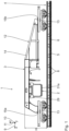
- Fig. 1
- eine Seitenansicht einer Vorrichtung zum Positionieren von mindestens zwei Gleisbearbeitungsgeräten am Gleis mit einem auf dem Gleis angeordneten Fahrwagen zum Befahren von Schienen,
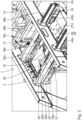
- Fig. 2
- eine perspektivische Darstellung eines Gleisbearbeitungssystems mit der Vorrichtung in
Fig. 1 und mit zwei daran angebrachten Gleisbearbeitungsgeräten, welche als Stopfaggregate ausgebildet ist, - Fig. 3
- eine vergrößerte Darstellung des Ausschnitts III in
Fig. 2 , - Fig. 4
- eine ausschnittsweise Seitenansicht des Gleisbearbeitungssystems in
Fig. 2 , - Fig. 5
- eine ausschnittsweise Draufsicht auf das Gleisbearbeitungssystems in
Fig. 2 , - Fig. 6
- eine Rückansicht des Gleisbearbeitungssystems in
Fig. 2 , - Fig. 7
- eine perspektivische Darstellung einer ersten Dreheinheit, einer ersten Querpositioniereinheit und eines ersten Tragmoduls des Gleisbearbeitungssystems in
Fig. 2 , - Fig. 8
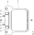
- eine perspektivische Darstellung eines Geräteträgers des Gleisbearbeitungssystems in
Fig. 2 , - Fig. 9
- eine ausschnittsweise Seitenansicht des Gleisbearbeitungssystems in
Fig. 2 , insbesondere eines Geräteträgers zum Tragen des Gleisbearbeitungsgeräts, - Fig. 10
- eine Rückansicht eines Gleisbearbeitungssystems in
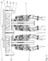
Fig. 2 , mit insgesamt vier der Gleisbearbeitungsgeräte, welche jeweils an einem der Geräteträger angebracht sind, wobei die Geräteträger in einer Transportstellung angeordnet sind, - Fig. 11
- eine Rückansicht des Gleisbearbeitungssystems in
Fig. 10 , wobei die Geräteträger in einer ersten Arbeitsstellung angeordnet sind, - Fig. 12
- eine Rückansicht des Gleisbearbeitungssystems in
Fig. 10 , wobei die Geräteträger in einer zweiten Arbeitsstellung angeordnet sind, - Fig. 13
- eine Schnittdarstellung entlang der Schnittlinie XIII-XIII in
Fig. 9 , - Fig. 14
- eine Draufsicht auf das Gleisbearbeitungssystem in
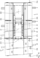
Fig. 2 in der Transportstellung, und - Fig. 15
- eine Draufsicht auf das Gleisbearbeitungssystem in
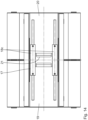
Fig. 2 , wobei dessen Anordnungen in der Transportstellung, in der ersten Arbeitsstellung und in der zweiten Arbeitsstellung einander überlappend dargestellt sind. - Anhand der
Fig. 1 bis Fig. 15 ist ein erstes Ausführungsbeispiel eines Gleisbearbeitungssystems 1 beschrieben. Das Gleisbearbeitungssystem 1 umfasst mindestens ein Gleisbearbeitungsgerät 2 und eine Vorrichtung 3 zum Positionieren des mindestens einen Gleisbearbeitungsgeräts 2 am Gleis 4. Die Gleisbearbeitungsgeräte 2 sind an der Vorrichtung 3 lösbar angebracht. Insbesondere ist die Vorrichtung 3 dazu ausgebildet, eine wechselnde Anzahl an Gleisbearbeitungsgeräten 2, insbesondere mindestens ein Gleisbearbeitungsgerät 2, zu tragen. In denFig. 1 bis Fig. 6 ist das Gleisbearbeitungssystem 1 mit zwei an der Vorrichtung 3 angebrachten Gleisbearbeitungsgeräten 2 gezeigt. In denFig. 10 bis Fig. 12 sind vier der Gleisbearbeitungsgeräte 2 an der Vorrichtung 3 angebracht. Die Vorrichtung 3 ist zum Tragen und zum Positionieren von maximal 8 Gleisbearbeitungsgeräten 2 ausgebildet. - Die Gleisbearbeitungsgeräte 2 sind jeweils als Stopfaggregate zum Verdichten eines Schotterbetts 5 des Gleises 4 ausgebildet. Gemäß einer nicht dargestellten alternativen Ausführungsform kann mindestens eines der Gleisbearbeitungsgeräte als Schraubaggregat, insbesondere zum Anziehen und Lösen von Schraubverbindungen, insbesondere von Schraubverbindungen zum Befestigen von Schienen 6, und/oder als Schweißaggregat, insbesondere zum Schweißen der Schienen 6, und/oder als Schleifaggregat, insbesondere zum Schleifen der Schienen 6, und/oder als Reinigungsaggregat, insbesondere zum Reinigen des Gleises 4, ausgebildet sein.
- Die Stopfaggregate 2 weisen jeweils mindestens zwei, insbesondere vier, Stopfpickel 7 zum reversiblen Eindringen in das Schotterbett beim Verdichten auf. Die Stopfpickel 7 sind derart paarweise angeordnet, dass diese beidseitig von einer Gleisschwelle 8 in das Schotterbett 5 eindringen können, um den Schotter unter die jeweilige Gleisschwelle 8 zu fördern. Die paarweise angeordneten Stopfpickel 7 sind hierzu in Längsrichtung 9 der Schienen 6 beabstandet zueinander angeordnet.
- Die Längsrichtung 9 ist parallel zu den Schienen 6 orientiert. Eine Querrichtung 10 ist horizontal und senkrecht zu der Längsrichtung 9 orientiert. Eine Vertikalrichtung 11 ist senkrecht zu der Längsrichtung 9 und zu der Querrichtung 10 orientiert.
- Die Vorrichtung 3 weist einen Fahrwagen 12 zum Befahren der Schienen 6 auf. Der Fahrwagen 12 umfasst zwei Drehgestelle 13 und ist als fahrantriebsloser Anhänger ausgebildet. Alternativ kann der Fahrwagen 12 einen Fahrmotor zum angetriebenen Befahren der Schienen 6 aufweisen.
- Der Fahrwagen 12 weist einen Fahrwagenträger 14 auf mit einem ersten Auflager 15a und einem zweiten Auflager 15b zum Abstützen auf dem jeweiligen Drehgestell 13.
- Die Vorrichtung 3 weist eine erste Querpositioniereinrichtung 16 und eine zweite Querpositioniereinrichtung 17 auf. Die zweite Querpositioniereinrichtung 17 weist zwei linear zueinander verlagerbare Querpositionierteile 18a, 18b auf. Ferner umfasst die zweite Querpositioniereinrichtung 17 einen Querpositionierantrieb 18c zum linearen Antreiben der Querpositionierteile 18a, 18b relativ zueinander. Das erste Querpositionierteil 18a ist an dem Fahrwagenträger 14, insbesondere starr, angebracht. Das zweite Querpositionierteil 18b ist relativ zu dem ersten Querpositionierteil 18a entlang einer zweiten Querpositionierrichtung 18d verlagerbar. Die zweite Querpositionierrichtung 18d ist schräg, insbesondere senkrecht, zu dem Gleis 4 und horizontal, insbesondere parallel zu der Querrichtung 10, orientiert.
- Die erste Querpositioniereinrichtung 16 ist an der zweiten Querpositioniereinrichtung 17 derart angebracht, dass die erste Querpositioniereinrichtung 16 schräg, insbesondere senkrecht, zu dem Gleis 4 und horizontal, insbesondere entlang der Querrichtung 10, linear verlagerbar ist. Die erste Querpositioniereinrichtung 16 weist zwei Querpositioniereinheiten 19, 20 auf. Die beiden Querpositioniereinheiten 19, 20 sind identisch ausgebildet. Ferner umfasst die erste Querpositioniereinrichtung 16 einen Querpositionierträger 21 und zwei Querpositioniereinheit-Antriebe 22a, 22b. Der Querpositionierträger 21 ist an dem zweiten Querpositionierteil 18b der zweiten Querpositioniereinrichtung 17, insbesondere starr, angebracht. Der jeweilige Querpositioniereinheit-Antrieb 22a, 22b ist zum Verlagern einer der Querpositioniereinheiten 19, 20 unabhängig von der anderen Querpositioniereinheit 19, 20 entlang einer ersten Querpositionierrichtung 23 ausgebildet. Die erste Querpositionierrichtung 23 ist parallel zu der zweiten Querpositionierrichtung 18d und zu der Querrichtung 10 orientiert.
- Die Vorrichtung 3 weist eine Dreheinrichtung 24 mit zwei Dreheinheiten 25, 26 auf. Die erste Dreheinheit 25 ist an der ersten Querpositioniereinheit 19 angebracht. Die zweite Dreheinheit 26 ist an der zweiten Querpositioniereinheit 20 angebracht. Insbesondere ist die Dreheinrichtung 24 mit der ersten Querpositioniereinrichtung 16 und der zweiten Querpositioniereinrichtung 17 derart verbunden, dass die Dreheinrichtung 24 schräg, insbesondere senkrecht, zu dem Gleis 4 und horizontal, insbesondere in Querrichtung 10, linear verlagerbar ist.
- Die erste Dreheinheit 25 weist zwei relativ zueinander drehbare Drehteile 27a, 27b auf. Die zweite Dreheinheit 26 weist zwei relativ zueinander drehbare Drehteile 28a, 28b auf. Die beiden Dreheinheiten 25, 26 verfügen jeweils über einen Drehantrieb 27c, 28c. Die Drehantriebe 27c, 28c sind zum Drehantreiben, insbesondere zum Schwenken, des jeweiligen ersten Drehteils 27a, 28a relativ zu dem zweiten Drehteil 27b, 28b um je eine Drehachse 27d, 28d ausgebildet. Die erste Dreheinheit 25, insbesondere deren erstes Drehteil 27a, ist an der ersten Querpositioniereinheit 19 angebracht. Die zweite Dreheinheit 26, insbesondere deren erstes Drehteil 28a, ist an der zweiten Querpositioniereinheit 20 angebracht. Die beiden Drehachsen 27d, 28d sind vertikal, insbesondere parallel zu der Vertikalrichtung 11, orientiert.
- Die Vorrichtung 3 weist zwei Tragmodule 29, 30 auf. Das erste Tragmodul ist an der ersten Dreheinheit 25, insbesondere an dem zweiten Drehteil 27b, angebracht. Das zweite Tragmodul 30 ist an der zweiten Dreheinheit 26, insbesondere an dem zweiten Drehteil 28b, angebracht. Die Tragmodule 29, 30 sind identisch ausgebildet. Die Tragmodule 29, 30 umfassen jeweils zwei Geräteträger 31a, 31b zum Tragen jeweils mindestens eines Gleisbearbeitungsgeräts 2 und eine Horizontalpositioniereinrichtung 32 zum Verlagern der Geräteträger 31a, 31b in einer Horizontalrichtung 33a, 33b, 33c. Ferner umfassen die Horizontalpositioniereinrichtungen 32 Horizontalpositionier-Antriebe 34a, 34b zum Verlagern der Geräteträger 31a, 31b entlang der Horizontalrichtung 33a, 33b, 33c.
- Die Tragmodule 29, 30, insbesondere die Geräteträger 31a, 31b, weisen jeweils eine Vertikalpositioniereinrichtung 35 zum Verlagern der Gleisbearbeitungsgeräte 2 entlang der Vertikalrichtung 11 auf. Die Vertikalpositioniereinrichtungen 35 umfassen zum automatisierten Verlagern Vertikalpositionier-Antriebe 36a, 36b.
- Vorzugsweise sind sämtliche der vorstehend beschriebenen Antriebe 18c, 22a, 22b, 27c, 28c, 34a, 34b, 36a, 36b als fluidische Antriebe, insbesondere als Kolb-Zylinder-Aktoren, insbesondere als Hydraulikzylinder, ausgebildet.
- Die Vorrichtung 3 weist eine Abstützeinrichtung 37 zum Abstützen der beiden Tragmodule 29, 30 in Vertikalrichtung 11, insbesondere in Längsrichtung 9, auf. Die Abstützeinrichtung 37 umfasst zwei relativ zueinander linear verlagerbare Abstützteile 38a, 38b. Das erste Abstützteil 38a ist, insbesondere starr, an dem Fahrwagenträger 14 angebracht. Das zweite Abstützteil 38b ist reversibel an dem ersten Tragmodul 29 oder an dem zweiten Tragmodul 30 anbringbar. Das erste Abstützteil 38a umfasst zwei Abstützträger 39a, 39b. Das zweite Abstützteil 38b umfasst zwei jeweils in einem der Abstützträger 39a, 39b linear verschiebbar aufgenommene Teleskopträger 40a, 40b.
- Die Vorrichtung 3 weist eine Transportsicherung 41a, 41b auf zum reversiblen Arretieren der ersten Querpositioniereinrichtung 16 und der zweiten Querpositioniereinrichtung 17 in einer Transportstellung.
- In der Transportstellung ist das Gleisbearbeitungssystem 1, insbesondere sind die Vorrichtung 3 und die Gleisbearbeitungsgeräte 2, vollständig innerhalb eines vorgegebenen Lichtraumprofils 42 des Gleises 4 angeordnet.
- Eine vertikale Gleismittenebene 43 ist parallel zu der Längsrichtung 9 und der Vertikalrichtung 11 orientiert und verläuft in Hinblick auf die Querrichtung 10 mittig zwischen den Schienen 6 und/oder mittig durch die Vorrichtung 3, insbesondere die in der Transportstellung angeordnete Vorrichtung 3. Ein Abstand xT1 zwischen der vertikalen Gleismittenebene 43 und dem ersten Geräteträger 31a, insbesondere dessen Mittelpunkt entlang der Querrichtung 10, beträgt in der Transportstellung 800 mm. Der Abstand xT1 beträgt in einer Arbeitsstellung maximal 2600 mm. Der erste Geräteträger 31a ist also, insbesondere mittels der Querpositioniereinrichtungen 16, 17 und der Horizontalpositioniereinrichtung 32, um 1800 mm entlang der Querrichtung 10 verlagerbar.
- Ein Abstand xT2 zwischen der vertikalen Gleismittenebene 43 und dem zweiten Geräteträger 31b beträgt 650 mm. Der zweite Geräteträger 31b ist ebenfalls um 1800 mm entlang der Querrichtung 10 verlagerbar.
- Ein Abstand xP zwischen der vertikalen Gleismittenebene 43 und einer Außenkontur des mittels der Stopfpickel 7 bearbeitbaren Bereichs des Schotterbetts 5 beträgt in der Transportstellung 1300 mm. In einer Arbeitsstellung beträgt dieser Abstand xP maximal 3100 mm.
- Die Dreheinrichtung 24 und die erste Querpositioniereinrichtung 16 und/oder die zweite Querpositioniereinrichtung 17 und/oder die Horizontalpositioniereinrichtung 32 überlappen einander zumindest abschnittsweise in einer Horizontalrichtung. Hierdurch kann eine besonders niedrige Gesamtbauhöhe H der Vorrichtung 3 erzielt werden.
- Die Funktionsweise des Gleisbearbeitungssystems 1, insbesondere der Vorrichtung 3, ist wie folgt:
Der Fahrwagen 12 ist auf dem Gleis 4 angeordnet. Die Gleisstopfaggregate 2 sind an den Geräteträgern 31a, 31b, insbesondere an der jeweiligen Vertikalpositioniereinrichtung 35 angebracht. Die Geräteträger 31a, 31b sind an der Horizontalpositioniereinrichtung 32 des jeweiligen Tragmoduls 29, 30 angebracht. Die Tragmodule 29, 30 sind jeweils an einer der Dreheinheiten 25, 26 der Dreheinrichtung 24 angebracht. Die Dreheinheiten 25, 26 sind jeweils an einer der Querpositioniereinheiten 19, 20 der ersten Querpositioniereinrichtung 16 angebracht. Die erste Querpositioniereinrichtung 16 ist an der zweiten Querpositioniereinrichtung 17 angebracht, welche an dem Fahrwagenträger 14 des Fahrwagens 12 befestigt ist. Die Vorrichtung 3 befindet sich in der Transportstellung, also vollständig innerhalb des Lichtraumprofils 42. Das Gleisbearbeitungssystem 1, insbesondere die Vorrichtung 3, ist insbesondere in derFig. 10 in der Transportstellung dargestellt. Die Querpositioniereinrichtungen 16, 17 sind mittels der Transportsicherung 41a, 41b in der Transportstellung arretiert. - Mittels eines nicht dargestellten Zugwagens wird der Fahrwagen 12 zu dem zu bearbeitenden Abschnitt des Gleises 4 transportiert. Die Transportsicherung 41a, 41b wird gelöst und die Gleisbearbeitungsgeräte 2 werden entsprechend ihrer Bearbeitungsaufgabe, vorliegend dem Verdichten des Schotterbetts 5, an dem Gleis 4 angeordnet.
- In der
Fig. 11 ist das Gleisbearbeitungssystem, insbesondere die Vorrichtung 3, in einer ersten Arbeitsstellung dargestellt. Der jeweilige Stellzustand der ersten Querpositioniereinrichtung 16 und der Dreheinrichtung 24 ist gegenüber der Transportstellung unverändert. Mittels des Querpositionierantriebs 18c ist das zweite Querpositionierteil 18b entlang der zweiten Querpositionierrichtung 18d relativ zu dem ersten Querpositionierteil 18a verlagert. Da mittels der zweiten Querpositioniereinrichtung 17 sämtliche Gleisbearbeitungsgeräte 2, insbesondere die mit den beiden Tragmodule 29, 30 verbundenen Gleisbearbeitungsgeräte 2, synchron verlagerbar sind, wird das Positionieren der Gleisbearbeitungsgeräte 2 in Gleiskurven in besonders einfacher, insbesondere einfach zu steuernder, Weise ermöglicht. Mittels der Horizontalpositioniereinrichtung 32 sind die Gleisbearbeitungsgeräte 2 geringfügig entlang der jeweiligen Horizontalrichtung 33a verlagert. Mittels der Vertikalpositioniereinrichtung 35 sind die Gleisbearbeitungsgeräte 2 gegenüber der Transportstellung in vertikaler Richtung nach unten verlagert. - In der
Fig. 12 ist das Gleisbearbeitungssystem 1, insbesondere die Vorrichtung 3 in einer zweiten Arbeitsstellung dargestellt. Gegenüber der Transportstellung und gegenüber der ersten Arbeitsstellung ist der Stellzustand der Querpositioniereinrichtungen 16, 17 der Dreheinrichtung 24 verändert. - Ferner sind die Gleisbearbeitungsgeräte 2 mittels der Horizontalpositioniereinrichtung 32 weiter nach außen, also weiter beabstandet zu der vertikalen Gleismittenebene 43, ausgefahren. Insbesondere sind die Abstände xP und xT1 zwischen der vertikalen Gleismittenebene 43 und der Außenkontur des bearbeitbaren Bereichs des Gleises 4 beziehungsweise der Mitte des Geräteträgers 31a maximal. Die Querpositioniereinrichtungen 16, 17 und die Horizontalpositioniereinrichtung 32 sind hierzu maximal, insbesondere entlang der Querrichtung 10, ausgefahren.
- Das Gleisbearbeitungssystem 1 ist im Bereich einer Weiche 44 angeordnet. Neben den Schienen 6, auf denen der Fahrwagen 12, insbesondere die Drehgestelle 13, angeordnet ist, sind in der
Fig. 12 Schienen 45 eines benachbartes Gleis 46 dargestellt. Eine Längsrichtung 47 der Schienen 45 ist schräg zu der Längsrichtung 9 der Schienen 6 orientiert. - Zum Bearbeiten der Schienen 45 des benachbarten Gleis 46 werden die Gleisbearbeitungsgeräte 2, insbesondere relativ zu dem Fahrwagen 12, in Querrichtung 10 verlagert. Mittels der ersten Querpositioniereinrichtung 16 und der Horizontalpositioniereinrichtung 32 können die beiden Tragmodule 29, 30 unabhängig voneinander entlang der Querrichtung 10 verlagert werden. Hierdurch können die Gleisbearbeitungsgeräte 2, welche an dem ersten Tragmodul 29 angebracht sind, zum Bearbeiten des benachbarten Gleises 46 positioniert werden, wobei die Gleisbearbeitungsgeräte 2, welche an dem zweiten Tragmodul 30 angebracht sind, zum Bearbeiten des Gleises 4 verwendet werden können.
- Die Dreheinrichtungen 24 sind zum voneinander unabhängigen rotatorischen Verlagern der beiden Tragmodule 29, 30 um die jeweilige Drehachse 27d, 28d über einen Winkelbereich von α = ±7° zur Querrichtung 10 ausgebildet. Hierdurch können die Gleisbearbeitungsgeräte 2 der jeweiligen Tragmodule 29, 30 voneinander unabhängig an die Orientierung, insbesondere die jeweilige Längsrichtung 9, 47, des jeweiligen Gleises 4, 46 angepasst werden, insbesondere entsprechend der jeweiligen Längsrichtung 9, 47 ausgerichtet werden. Insbesondere kann das erste Tragmodul 29 entsprechend der Längsrichtung 47 des benachbarten Gleises 46 orientiert werden. Das zweite Tragmodul 30 kann an die lokale Längsrichtung 9 des Gleises 4 angepasst werden, welche sich insbesondere relativ zu dem Fahrwagen 12, aufgrund des sogenannten Sekantenversatzes, verändern kann. Dadurch, dass beide Tragmodule 29, 30 voneinander unabhängig an die jeweilige Längsrichtung 9, 47 der Gleise 4, 46 anpassbar sind, ist das Gleisbearbeitungssystem 1 besonders zeit- und energieeffizient im Einsatz und somit besonders wirtschaftlich im Betrieb.
- Mittels der zweiten Querpositioniereinrichtung 17 können sämtliche der Gleisbearbeitungsgeräte 2 synchron entlang der Querrichtung 10 verlagert werden. Eine entsprechend synchrone Querverlagerung der Gleisbearbeitungsgeräte 2 ist besonders geeignet für die Bearbeitung eines einzelnen Gleises 4. Insbesondere im Bereich von Kurven können die Gleisbearbeitungsgeräte 2 zuverlässig gemeinsam verlagert werden. Hierdurch ist das Gleisbearbeitungssystem 1 besonders robust im Betrieb, einfach steuerbar und benutzerfreundlich in der Handhabung.
- Dadurch, dass die Vorrichtung 3 die erste Querpositioniereinrichtung 16, die zweite Querpositioniereinrichtung 17 und/oder die Horizontalpositioniereinrichtung 32 aufweist, können die Geräteträger 31a, 31b, insbesondere die Gleisbearbeitungsgeräte 2, in einer Arbeitsstellung in Querrichtung 10 besonders weit von der vertikalen Gleismittenebene 43 entfernt positioniert werden. In der Transportstellung ragt das Gleisbearbeitungssystem 1, insbesondere die Vorrichtung 3, jedoch nicht über das vorgegebene Lichtraumprofil 42 hinaus. Die Vorrichtung 3 gewährleistet das Bearbeiten von Gleisen 4, 46 in besonders zeiteffizienter und flexibler Weise.
Claims (13)
- Vorrichtung (3) zum Positionieren von Gleisbearbeitungsgeräten (2) am Gleis (4, 46), aufweisend1.1. mindestens zwei Tragmodule (29, 30), mit jeweils1.1.1. mindestens einem Geräteträger (31a, 31b) zum Tragen mindestens eines Gleisbearbeitungsgeräts (2), und1.1.2. einer Horizontalpositioniereinrichtung (32), an welcher der mindestens eine Geräteträger (31a, 31b) angebracht ist, zum Verlagern des mindestens einen Geräteträgers (31a, 31b) entlang einer Horizontalrichtung (33a, 33b, 33c),1.2. eine Dreheinrichtung (24) zum rotatorischen Verlagern der mindestens zwei Tragmodule (29, 30),
1.2.1. wobei die Dreheinrichtung (24) mindestens zwei Dreheinheiten (25, 26) zum jeweils voneinander unabhängigen rotatorischen Verlagern der mindestens zwei Tragmodule (29, 30) aufweist, und1.3. eine erste Querpositioniereinrichtung (16) zum linearen Verlagern der mindestens zwei Tragmodule (29, 30) entlang der Horizontalrichtung (33a, 33b, 33c) und in einem Winkel von mindestens 45° zur Längsrichtung (9) des Gleises (4). - Vorrichtung (3) nach Anspruch 1, dadurch gekennzeichnet, dass die erste Querpositioniereinrichtung (16) mindestens zwei Querpositioniereinheiten (19, 20) zum jeweils voneinander unabhängigen linearen Verlagern der mindestens zwei Tragmodule (29, 30) aufweist.
- Vorrichtung (3) nach einem der vorstehenden Ansprüche, gekennzeichnet durch eine zweite Querpositioniereinrichtung (17) zum linearen Verlagern der mindestens zwei Tragmodule (29, 30) entlang einer Horizontalrichtung (33a, 33b, 33c) und schräg zu dem Gleis (4, 46).
- Vorrichtung (3) nach Anspruch 3, dadurch gekennzeichnet, dass die Dreheinrichtung (24) an der ersten Querpositioniereinrichtung (16) und/oder an der zweiten Querpositioniereinrichtung (17) angebracht ist, sodass die Dreheinrichtung (24) entlang der Horizontalrichtung (33a, 33b, 33c) und schräg zu dem Gleis (4, 46) linear verlagerbar ist.
- Vorrichtung (3) nach Anspruch 3 oder 4, dadurch gekennzeichnet, dass die erste Querpositioniereinrichtung (16) an der zweiten Querpositioniereinrichtung (17) angebracht ist, sodass die erste Querpositioniereinrichtung (16) entlang der Horizontalrichtung (33a, 33b, 33c) und schräg zu dem Gleis (4, 46) linear verlagerbar ist.
- Vorrichtung (3) nach einem der Ansprüche 3 bis 5, dadurch gekennzeichnet, dass die erste Querpositioniereinrichtung (16) und die zweite Querpositioniereinrichtung (17) parallel orientiert sind zum Verlagern der mindestens zwei Tragmodule (29, 30) in paralleler Richtung.
- Vorrichtung (3) nach einem der Ansprüche 3 bis 6, dadurch gekennzeichnet, dass die erste Querpositioniereinrichtung (16) und/oder die zweite Querpositioniereinrichtung (17) zum Verlagern der mindestens zwei Tragmodule (29, 30) senkrecht zu dem Gleis (4, 46) ausgebildet sind.
- Vorrichtung (3) nach einem der Ansprüche 3 bis 7, dadurch gekennzeichnet, dass die erste Querpositioniereinrichtung (16) und/oder die zweite Querpositioniereinrichtung (17) zum Verlagern mindestens eines der Tragmodule (29, 30) über einen Querstellweg von mindestens 160 cm ausgebildet ist.
- Vorrichtung (3) nach einem der vorstehenden Ansprüche, gekennzeichnet durch eine Abstützeinrichtung (37) zum Abstützen der mindestens zwei Tragmodule (29, 30) beim Verlagern mittels der ersten Querpositioniereinrichtung (16) und/oder der zweiten Querpositioniereinrichtung (17).
- Vorrichtung (3) nach einem der vorstehenden Ansprüche, gekennzeichnet durch eine Transportsicherung (41a, 41b) zum reversiblen Arretieren der Dreheinrichtung (24) und/oder der ersten Querpositioniereinrichtung (16) und/oder der zweiten Querpositioniereinrichtung (17) in einer Transportstellung.
- Vorrichtung (3) nach einem der vorstehenden Ansprüche, gekennzeichnet durch einen Fahrwagen (12) zum Befahren von Schienen (6, 45), an dem die Dreheinrichtung (24) mittelbar oder unmittelbar angebracht ist.
- Gleisbearbeitungssystem (1), aufweisend12.1. eine Vorrichtung (3) nach einem der Ansprüche 1 bis 11, und12.2. mindestens ein Gleisbearbeitungsgerät (2), welches an dem mindestens einen Geräteträger (31a, 31b) angebracht ist.
- Gleisbearbeitungssystem (1) nach Anspruch 12, dadurch gekennzeichnet, dass das mindestens eine Gleisbearbeitungsgerät (2) ein Stopfaggregat und/oder ein Schraubaggregat ist.
Applications Claiming Priority (2)
| Application Number | Priority Date | Filing Date | Title |
|---|---|---|---|
| ATA50741/2021A AT525462B1 (de) | 2021-09-21 | 2021-09-21 | Vorrichtung zum Positionieren von Gleisbearbeitungsgeräten am Gleis und Gleisbearbeitungssytem |
| PCT/EP2022/074210 WO2023046430A1 (de) | 2021-09-21 | 2022-08-31 | Vorrichtung zum positionieren von gleisbearbeitungsgeräten am gleis |
Publications (3)
| Publication Number | Publication Date |
|---|---|
| EP4405526A1 EP4405526A1 (de) | 2024-07-31 |
| EP4405526C0 EP4405526C0 (de) | 2025-06-18 |
| EP4405526B1 true EP4405526B1 (de) | 2025-06-18 |
Family
ID=83361272
Family Applications (1)
| Application Number | Title | Priority Date | Filing Date |
|---|---|---|---|
| EP22772867.2A Active EP4405526B1 (de) | 2021-09-21 | 2022-08-31 | Vorrichtung zum positionieren von gleisbearbeitungsgeräten am gleis |
Country Status (7)
| Country | Link |
|---|---|
| US (1) | US20240384477A1 (de) |
| EP (1) | EP4405526B1 (de) |
| JP (1) | JP2024534522A (de) |
| CN (1) | CN117957348A (de) |
| AT (1) | AT525462B1 (de) |
| AU (1) | AU2022349714A1 (de) |
| WO (1) | WO2023046430A1 (de) |
Family Cites Families (4)
| Publication number | Priority date | Publication date | Assignee | Title |
|---|---|---|---|---|
| AT315227B (de) * | 1969-08-08 | 1974-05-10 | Plasser Bahnbaumasch Franz | Stopfwerkzeug für Gleisstopfmaschinen |
| AT392810B (de) * | 1989-04-18 | 1991-06-25 | Plasser Bahnbaumasch Franz | Fahrbare gleisstopfmaschine mit quer- und hoehenverstellbaren stopfaggregaten |
| AT399893B (de) * | 1992-05-06 | 1995-08-25 | Plasser Bahnbaumasch Franz | Gleisstopfmaschine |
| EP3271232B1 (de) | 2015-03-17 | 2020-03-04 | Harsco Technologies LLC | Schienenfahrzeug |
-
2021
- 2021-09-21 AT ATA50741/2021A patent/AT525462B1/de active
-
2022
- 2022-08-31 CN CN202280063230.5A patent/CN117957348A/zh active Pending
- 2022-08-31 US US18/694,060 patent/US20240384477A1/en active Pending
- 2022-08-31 AU AU2022349714A patent/AU2022349714A1/en active Pending
- 2022-08-31 JP JP2024517490A patent/JP2024534522A/ja active Pending
- 2022-08-31 EP EP22772867.2A patent/EP4405526B1/de active Active
- 2022-08-31 WO PCT/EP2022/074210 patent/WO2023046430A1/de not_active Ceased
Also Published As
| Publication number | Publication date |
|---|---|
| US20240384477A1 (en) | 2024-11-21 |
| WO2023046430A1 (de) | 2023-03-30 |
| AT525462B1 (de) | 2025-10-15 |
| EP4405526C0 (de) | 2025-06-18 |
| CN117957348A (zh) | 2024-04-30 |
| AU2022349714A1 (en) | 2024-03-07 |
| JP2024534522A (ja) | 2024-09-20 |
| AT525462A1 (de) | 2023-04-15 |
| EP4405526A1 (de) | 2024-07-31 |
Similar Documents
| Publication | Publication Date | Title |
|---|---|---|
| DE2832095C2 (de) | ||
| DE102012107295A1 (de) | Werkzeugmaschine | |
| DE602004000024T2 (de) | Werkzeugsmaschine mit einer verfahrbaren Brücke, ein Werkzeugmagazin und zwei Werkzeugswechselvorrichtungen | |
| WO2017080760A1 (de) | Werkzeugmaschine mit einseitig angetriebenem werkstückträger | |
| DE3702108A1 (de) | Vorrichtung zum umsetzen von werkstuecken | |
| DD225732A5 (de) | Maschine zum richtigen positionieren und zum stumpfschweissen von zwei schienenenden | |
| EP2897764B1 (de) | Werkstückwechsler und werkzeugmaschine mit einem solchen werkstückwechsler | |
| AT403812B (de) | Maschine zum anpressen von schwellenankern | |
| EP0700733A1 (de) | Vorrichtung zum Reinigen und/oder Entgraten von Werkstücken mittels eines Flüssigkeits-Spritzstrahls | |
| DE102017116718A1 (de) | Bearbeitungsanlage für Flugzeugstrukturbauteile | |
| DE3416033A1 (de) | Gleisbaumaschine, deren fahrgestell mit einer vorrichtung zum heben und richten eines gleises ausgeruestet ist | |
| DE4439615B4 (de) | Papierbahnzuführung zu einem Falzapparat | |
| EP0312031B1 (de) | Vorrichtung zum Führen der Greiferstangen an einer Greiferwebmaschine | |
| WO2016157078A1 (de) | Bearbeitungsmaschine | |
| WO2004108349A2 (de) | Werkzeugmaschine mit einspannvorrichtung auf beiden seiten | |
| AT525462B1 (de) | Vorrichtung zum Positionieren von Gleisbearbeitungsgeräten am Gleis und Gleisbearbeitungssytem | |
| EP1566243B1 (de) | Vorrichtung zum Positionieren und Antreiben eines Arbeitswerkzeuges | |
| DE602004000620T2 (de) | Bohrmaschine für alle Richtungen | |
| DE102017213361A1 (de) | Wälzfräsmaschine, umfassend einen Wälzfrässchlitten und einen Anfasschlitten auf einem gemeinsamen Schienensystem | |
| DE2740211C2 (de) | Vorrichtung zum Antreiben eines Paares Greiferschienen in Längsrichtung | |
| EP3879032B1 (de) | Stelleinrichtung zum positionieren eines bearbeitungswerkzeuges relativ zu einer schiene | |
| EP3144101B1 (de) | Werkzeugmaschine mit einer funktionsbaugruppe | |
| EP0624543B1 (de) | Vorrichtung zur Aufnahme, zum Transport und zur Positionierung von Fahrzeugen | |
| DE19838964C2 (de) | Diagonalsäge | |
| EP2371482A1 (de) | Werkzeugmaschine |
Legal Events
| Date | Code | Title | Description |
|---|---|---|---|
| STAA | Information on the status of an ep patent application or granted ep patent |
Free format text: STATUS: UNKNOWN |
|
| STAA | Information on the status of an ep patent application or granted ep patent |
Free format text: STATUS: THE INTERNATIONAL PUBLICATION HAS BEEN MADE |
|
| PUAI | Public reference made under article 153(3) epc to a published international application that has entered the european phase |
Free format text: ORIGINAL CODE: 0009012 |
|
| STAA | Information on the status of an ep patent application or granted ep patent |
Free format text: STATUS: REQUEST FOR EXAMINATION WAS MADE |
|
| 17P | Request for examination filed |
Effective date: 20240422 |
|
| AK | Designated contracting states |
Kind code of ref document: A1 Designated state(s): AL AT BE BG CH CY CZ DE DK EE ES FI FR GB GR HR HU IE IS IT LI LT LU LV MC MK MT NL NO PL PT RO RS SE SI SK SM TR |
|
| DAV | Request for validation of the european patent (deleted) | ||
| DAX | Request for extension of the european patent (deleted) | ||
| GRAP | Despatch of communication of intention to grant a patent |
Free format text: ORIGINAL CODE: EPIDOSNIGR1 |
|
| STAA | Information on the status of an ep patent application or granted ep patent |
Free format text: STATUS: GRANT OF PATENT IS INTENDED |
|
| INTG | Intention to grant announced |
Effective date: 20250211 |
|
| GRAS | Grant fee paid |
Free format text: ORIGINAL CODE: EPIDOSNIGR3 |
|
| GRAA | (expected) grant |
Free format text: ORIGINAL CODE: 0009210 |
|
| STAA | Information on the status of an ep patent application or granted ep patent |
Free format text: STATUS: THE PATENT HAS BEEN GRANTED |
|
| AK | Designated contracting states |
Kind code of ref document: B1 Designated state(s): AL AT BE BG CH CY CZ DE DK EE ES FI FR GB GR HR HU IE IS IT LI LT LU LV MC MK MT NL NO PL PT RO RS SE SI SK SM TR |
|
| REG | Reference to a national code |
Ref country code: GB Ref legal event code: FG4D Free format text: NOT ENGLISH |
|
| REG | Reference to a national code |
Ref country code: CH Ref legal event code: EP |
|
| REG | Reference to a national code |
Ref country code: DE Ref legal event code: R096 Ref document number: 502022004357 Country of ref document: DE |
|
| REG | Reference to a national code |
Ref country code: CH Ref legal event code: EP |
|
| REG | Reference to a national code |
Ref country code: IE Ref legal event code: FG4D Free format text: LANGUAGE OF EP DOCUMENT: GERMAN |
|
| U01 | Request for unitary effect filed |
Effective date: 20250618 |
|
| U07 | Unitary effect registered |
Designated state(s): AT BE BG DE DK EE FI FR IT LT LU LV MT NL PT RO SE SI Effective date: 20250627 |
|
| PG25 | Lapsed in a contracting state [announced via postgrant information from national office to epo] |
Ref country code: NO Free format text: LAPSE BECAUSE OF FAILURE TO SUBMIT A TRANSLATION OF THE DESCRIPTION OR TO PAY THE FEE WITHIN THE PRESCRIBED TIME-LIMIT Effective date: 20250918 Ref country code: GR Free format text: LAPSE BECAUSE OF FAILURE TO SUBMIT A TRANSLATION OF THE DESCRIPTION OR TO PAY THE FEE WITHIN THE PRESCRIBED TIME-LIMIT Effective date: 20250919 |
|
| PG25 | Lapsed in a contracting state [announced via postgrant information from national office to epo] |
Ref country code: HR Free format text: LAPSE BECAUSE OF FAILURE TO SUBMIT A TRANSLATION OF THE DESCRIPTION OR TO PAY THE FEE WITHIN THE PRESCRIBED TIME-LIMIT Effective date: 20250618 |
|
| PGFP | Annual fee paid to national office [announced via postgrant information from national office to epo] |
Ref country code: CH Payment date: 20250901 Year of fee payment: 4 |
|
| PG25 | Lapsed in a contracting state [announced via postgrant information from national office to epo] |
Ref country code: RS Free format text: LAPSE BECAUSE OF FAILURE TO SUBMIT A TRANSLATION OF THE DESCRIPTION OR TO PAY THE FEE WITHIN THE PRESCRIBED TIME-LIMIT Effective date: 20250918 |
|
| U20 | Renewal fee for the european patent with unitary effect paid |
Year of fee payment: 4 Effective date: 20250929 |
|
| PG25 | Lapsed in a contracting state [announced via postgrant information from national office to epo] |
Ref country code: IS Free format text: LAPSE BECAUSE OF FAILURE TO SUBMIT A TRANSLATION OF THE DESCRIPTION OR TO PAY THE FEE WITHIN THE PRESCRIBED TIME-LIMIT Effective date: 20251018 |
|
| PG25 | Lapsed in a contracting state [announced via postgrant information from national office to epo] |
Ref country code: SM Free format text: LAPSE BECAUSE OF FAILURE TO SUBMIT A TRANSLATION OF THE DESCRIPTION OR TO PAY THE FEE WITHIN THE PRESCRIBED TIME-LIMIT Effective date: 20250618 |
|
| PG25 | Lapsed in a contracting state [announced via postgrant information from national office to epo] |
Ref country code: CZ Free format text: LAPSE BECAUSE OF FAILURE TO SUBMIT A TRANSLATION OF THE DESCRIPTION OR TO PAY THE FEE WITHIN THE PRESCRIBED TIME-LIMIT Effective date: 20250618 |
|
| PG25 | Lapsed in a contracting state [announced via postgrant information from national office to epo] |
Ref country code: PL Free format text: LAPSE BECAUSE OF FAILURE TO SUBMIT A TRANSLATION OF THE DESCRIPTION OR TO PAY THE FEE WITHIN THE PRESCRIBED TIME-LIMIT Effective date: 20250618 |
|
| PG25 | Lapsed in a contracting state [announced via postgrant information from national office to epo] |
Ref country code: SK Free format text: LAPSE BECAUSE OF FAILURE TO SUBMIT A TRANSLATION OF THE DESCRIPTION OR TO PAY THE FEE WITHIN THE PRESCRIBED TIME-LIMIT Effective date: 20250618 |
|
| PG25 | Lapsed in a contracting state [announced via postgrant information from national office to epo] |
Ref country code: ES Free format text: LAPSE BECAUSE OF FAILURE TO SUBMIT A TRANSLATION OF THE DESCRIPTION OR TO PAY THE FEE WITHIN THE PRESCRIBED TIME-LIMIT Effective date: 20250618 |
|
| PG25 | Lapsed in a contracting state [announced via postgrant information from national office to epo] |
Ref country code: MC Free format text: LAPSE BECAUSE OF FAILURE TO SUBMIT A TRANSLATION OF THE DESCRIPTION OR TO PAY THE FEE WITHIN THE PRESCRIBED TIME-LIMIT Effective date: 20250618 |
|
| PLBE | No opposition filed within time limit |
Free format text: ORIGINAL CODE: 0009261 |
|
| STAA | Information on the status of an ep patent application or granted ep patent |
Free format text: STATUS: NO OPPOSITION FILED WITHIN TIME LIMIT |
|
| REG | Reference to a national code |
Ref country code: CH Ref legal event code: L10 Free format text: ST27 STATUS EVENT CODE: U-0-0-L10-L00 (AS PROVIDED BY THE NATIONAL OFFICE) Effective date: 20260430 |