EP4404366A1 - Lithiumsekundärbatterie mit negativem elektrodenaktivmaterial auf si-basis - Google Patents
Lithiumsekundärbatterie mit negativem elektrodenaktivmaterial auf si-basis Download PDFInfo
- Publication number
- EP4404366A1 EP4404366A1 EP23824060.0A EP23824060A EP4404366A1 EP 4404366 A1 EP4404366 A1 EP 4404366A1 EP 23824060 A EP23824060 A EP 23824060A EP 4404366 A1 EP4404366 A1 EP 4404366A1
- Authority
- EP
- European Patent Office
- Prior art keywords
- separator
- secondary battery
- lithium secondary
- binder
- seconds
- Prior art date
- Legal status (The legal status is an assumption and is not a legal conclusion. Google has not performed a legal analysis and makes no representation as to the accuracy of the status listed.)
- Granted
Links
Images

Classifications
-
- H—ELECTRICITY
- H01—ELECTRIC ELEMENTS
- H01M—PROCESSES OR MEANS, e.g. BATTERIES, FOR THE DIRECT CONVERSION OF CHEMICAL ENERGY INTO ELECTRICAL ENERGY
- H01M4/00—Electrodes
- H01M4/02—Electrodes composed of, or comprising, active material
-
- H—ELECTRICITY
- H01—ELECTRIC ELEMENTS
- H01M—PROCESSES OR MEANS, e.g. BATTERIES, FOR THE DIRECT CONVERSION OF CHEMICAL ENERGY INTO ELECTRICAL ENERGY
- H01M50/00—Constructional details or processes of manufacture of the non-active parts of electrochemical cells other than fuel cells, e.g. hybrid cells
- H01M50/40—Separators; Membranes; Diaphragms; Spacing elements inside cells
- H01M50/489—Separators, membranes, diaphragms or spacing elements inside the cells, characterised by their physical properties, e.g. swelling degree, hydrophilicity or shut down properties
- H01M50/494—Tensile strength
-
- H—ELECTRICITY
- H01—ELECTRIC ELEMENTS
- H01M—PROCESSES OR MEANS, e.g. BATTERIES, FOR THE DIRECT CONVERSION OF CHEMICAL ENERGY INTO ELECTRICAL ENERGY
- H01M10/00—Secondary cells; Manufacture thereof
- H01M10/05—Accumulators with non-aqueous electrolyte
- H01M10/052—Li-accumulators
-
- H—ELECTRICITY
- H01—ELECTRIC ELEMENTS
- H01M—PROCESSES OR MEANS, e.g. BATTERIES, FOR THE DIRECT CONVERSION OF CHEMICAL ENERGY INTO ELECTRICAL ENERGY
- H01M10/00—Secondary cells; Manufacture thereof
- H01M10/05—Accumulators with non-aqueous electrolyte
- H01M10/052—Li-accumulators
- H01M10/0525—Rocking-chair batteries, i.e. batteries with lithium insertion or intercalation in both electrodes; Lithium-ion batteries
-
- H—ELECTRICITY
- H01—ELECTRIC ELEMENTS
- H01M—PROCESSES OR MEANS, e.g. BATTERIES, FOR THE DIRECT CONVERSION OF CHEMICAL ENERGY INTO ELECTRICAL ENERGY
- H01M4/00—Electrodes
- H01M4/02—Electrodes composed of, or comprising, active material
- H01M4/13—Electrodes for accumulators with non-aqueous electrolyte, e.g. for lithium-accumulators; Processes of manufacture thereof
- H01M4/134—Electrodes based on metals, Si or alloys
-
- H—ELECTRICITY
- H01—ELECTRIC ELEMENTS
- H01M—PROCESSES OR MEANS, e.g. BATTERIES, FOR THE DIRECT CONVERSION OF CHEMICAL ENERGY INTO ELECTRICAL ENERGY
- H01M4/00—Electrodes
- H01M4/02—Electrodes composed of, or comprising, active material
- H01M4/36—Selection of substances as active materials, active masses, active liquids
- H01M4/362—Composites
- H01M4/364—Composites as mixtures
-
- H—ELECTRICITY
- H01—ELECTRIC ELEMENTS
- H01M—PROCESSES OR MEANS, e.g. BATTERIES, FOR THE DIRECT CONVERSION OF CHEMICAL ENERGY INTO ELECTRICAL ENERGY
- H01M4/00—Electrodes
- H01M4/02—Electrodes composed of, or comprising, active material
- H01M4/36—Selection of substances as active materials, active masses, active liquids
- H01M4/38—Selection of substances as active materials, active masses, active liquids of elements or alloys
- H01M4/386—Silicon or alloys based on silicon
-
- H—ELECTRICITY
- H01—ELECTRIC ELEMENTS
- H01M—PROCESSES OR MEANS, e.g. BATTERIES, FOR THE DIRECT CONVERSION OF CHEMICAL ENERGY INTO ELECTRICAL ENERGY
- H01M4/00—Electrodes
- H01M4/02—Electrodes composed of, or comprising, active material
- H01M4/36—Selection of substances as active materials, active masses, active liquids
- H01M4/48—Selection of substances as active materials, active masses, active liquids of inorganic oxides or hydroxides
- H01M4/483—Selection of substances as active materials, active masses, active liquids of inorganic oxides or hydroxides for non-aqueous cells
-
- H—ELECTRICITY
- H01—ELECTRIC ELEMENTS
- H01M—PROCESSES OR MEANS, e.g. BATTERIES, FOR THE DIRECT CONVERSION OF CHEMICAL ENERGY INTO ELECTRICAL ENERGY
- H01M4/00—Electrodes
- H01M4/02—Electrodes composed of, or comprising, active material
- H01M4/36—Selection of substances as active materials, active masses, active liquids
- H01M4/58—Selection of substances as active materials, active masses, active liquids of inorganic compounds other than oxides or hydroxides, e.g. sulfides, selenides, tellurides, halogenides or LiCoFy; of polyanionic structures, e.g. phosphates, silicates or borates
- H01M4/583—Carbonaceous material, e.g. graphite-intercalation compounds or CFx
- H01M4/587—Carbonaceous material, e.g. graphite-intercalation compounds or CFx for inserting or intercalating light metals
-
- H—ELECTRICITY
- H01—ELECTRIC ELEMENTS
- H01M—PROCESSES OR MEANS, e.g. BATTERIES, FOR THE DIRECT CONVERSION OF CHEMICAL ENERGY INTO ELECTRICAL ENERGY
- H01M50/00—Constructional details or processes of manufacture of the non-active parts of electrochemical cells other than fuel cells, e.g. hybrid cells
- H01M50/40—Separators; Membranes; Diaphragms; Spacing elements inside cells
- H01M50/409—Separators, membranes or diaphragms characterised by the material
- H01M50/411—Organic material
- H01M50/414—Synthetic resins, e.g. thermoplastics or thermosetting resins
- H01M50/417—Polyolefins
-
- H—ELECTRICITY
- H01—ELECTRIC ELEMENTS
- H01M—PROCESSES OR MEANS, e.g. BATTERIES, FOR THE DIRECT CONVERSION OF CHEMICAL ENERGY INTO ELECTRICAL ENERGY
- H01M50/00—Constructional details or processes of manufacture of the non-active parts of electrochemical cells other than fuel cells, e.g. hybrid cells
- H01M50/40—Separators; Membranes; Diaphragms; Spacing elements inside cells
- H01M50/409—Separators, membranes or diaphragms characterised by the material
- H01M50/446—Composite material consisting of a mixture of organic and inorganic materials
-
- H—ELECTRICITY
- H01—ELECTRIC ELEMENTS
- H01M—PROCESSES OR MEANS, e.g. BATTERIES, FOR THE DIRECT CONVERSION OF CHEMICAL ENERGY INTO ELECTRICAL ENERGY
- H01M50/00—Constructional details or processes of manufacture of the non-active parts of electrochemical cells other than fuel cells, e.g. hybrid cells
- H01M50/40—Separators; Membranes; Diaphragms; Spacing elements inside cells
- H01M50/409—Separators, membranes or diaphragms characterised by the material
- H01M50/449—Separators, membranes or diaphragms characterised by the material having a layered structure
- H01M50/451—Separators, membranes or diaphragms characterised by the material having a layered structure comprising layers of only organic material and layers containing inorganic material
-
- H—ELECTRICITY
- H01—ELECTRIC ELEMENTS
- H01M—PROCESSES OR MEANS, e.g. BATTERIES, FOR THE DIRECT CONVERSION OF CHEMICAL ENERGY INTO ELECTRICAL ENERGY
- H01M50/00—Constructional details or processes of manufacture of the non-active parts of electrochemical cells other than fuel cells, e.g. hybrid cells
- H01M50/40—Separators; Membranes; Diaphragms; Spacing elements inside cells
- H01M50/409—Separators, membranes or diaphragms characterised by the material
- H01M50/449—Separators, membranes or diaphragms characterised by the material having a layered structure
- H01M50/457—Separators, membranes or diaphragms characterised by the material having a layered structure comprising three or more layers
-
- H—ELECTRICITY
- H01—ELECTRIC ELEMENTS
- H01M—PROCESSES OR MEANS, e.g. BATTERIES, FOR THE DIRECT CONVERSION OF CHEMICAL ENERGY INTO ELECTRICAL ENERGY
- H01M50/00—Constructional details or processes of manufacture of the non-active parts of electrochemical cells other than fuel cells, e.g. hybrid cells
- H01M50/40—Separators; Membranes; Diaphragms; Spacing elements inside cells
- H01M50/489—Separators, membranes, diaphragms or spacing elements inside the cells, characterised by their physical properties, e.g. swelling degree, hydrophilicity or shut down properties
- H01M50/491—Porosity
-
- H—ELECTRICITY
- H01—ELECTRIC ELEMENTS
- H01M—PROCESSES OR MEANS, e.g. BATTERIES, FOR THE DIRECT CONVERSION OF CHEMICAL ENERGY INTO ELECTRICAL ENERGY
- H01M4/00—Electrodes
- H01M4/02—Electrodes composed of, or comprising, active material
- H01M2004/026—Electrodes composed of, or comprising, active material characterised by the polarity
- H01M2004/027—Negative electrodes
-
- Y—GENERAL TAGGING OF NEW TECHNOLOGICAL DEVELOPMENTS; GENERAL TAGGING OF CROSS-SECTIONAL TECHNOLOGIES SPANNING OVER SEVERAL SECTIONS OF THE IPC; TECHNICAL SUBJECTS COVERED BY FORMER USPC CROSS-REFERENCE ART COLLECTIONS [XRACs] AND DIGESTS
- Y02—TECHNOLOGIES OR APPLICATIONS FOR MITIGATION OR ADAPTATION AGAINST CLIMATE CHANGE
- Y02E—REDUCTION OF GREENHOUSE GAS [GHG] EMISSIONS, RELATED TO ENERGY GENERATION, TRANSMISSION OR DISTRIBUTION
- Y02E60/00—Enabling technologies; Technologies with a potential or indirect contribution to GHG emissions mitigation
- Y02E60/10—Energy storage using batteries
Definitions
- the present disclosure relates to a lithium secondary battery including a Si-based anode active material as an anode active material.
- a separator for a lithium secondary battery As a separator for a lithium secondary battery, a film based on a polymer resin such as polyolefin and having a plurality of pores is used.
- an electrode assembly is manufactured through a lamination process in which a separator and an electrode are bonded by application of heat and pressure. The higher the heat and pressure applied to the separator, the higher the bonding force between the electrode and the separator. Recently, for the purpose of improving productivity, adhesion is secured by increasing application pressure because time of heat application to the separator is shortened as the process speeds up. However, the increase of application pressure may cause the electrode assembly to be deformed.
- the thickness of the polymer film substrate is significantly reduced and the damage to the pores increases, resulting in a decrease in the performance of a battery as well as a decrease in the dielectric breakdown voltage of the separator, resulting in increased Hi-pot defects and reduced capacity retention rates (CRR) .
- Si-based anode active material such as Si, SiO, or Si alloy
- the volume expansion of the anode is large, and thus the internal pressure of cells increases, resulting in intensified compression deformation of the separator.
- the Si-based anode active materials have a greater granularity, roughness, and hardness than graphite anode active materials, thereby causing local damage to the separator while lamination of the anode active material and the separator is performed.
- An objective of the present disclosure is to provide a lithium secondary battery including a Si-based anode active material, the lithium secondary battery having reduced Hi-pot defects and an improved capacity retention rate.
- a lithium secondary battery including an anode, a cathode, and a separator interposed between the anode and the cathode, in which the anode includes a Si-based anode active material, the separator includes a separator substrate having a plurality of pores and including a polyolefin resin, the polyolefin resin has a polydispersity index (PDI) of 2.5 to 4.2, an average pore size of 20 to 40 nm, and a maximum pore size of 50 nm or less.
- PDI polydispersity index
- a lithium secondary battery including an anode, a cathode, and a separator interposed between the anode and the cathode, in which
- a fourth aspect of the present disclosure provides a lithium secondary battery
- a fifth aspect of the present disclosure provides a lithium secondary battery
- a sixth aspect of the present disclosure provides a lithium secondary battery, in any one of the first to fifth aspects, the polyolefin resin has a weight average molecular weight of 500,000 to 1,500,000 g/mol.
- a seventh aspect of the present disclosure provides a lithium secondary battery, in any one of the first to sixth aspects, the separator substrate includes a core portion made of a mixture of polyethylene and polypropylene and a polyethylene skin portion provided on each of both surfaces of the core portion.
- the separator substrate is a separator substrate manufactured by a wet manufacturing method in which pores are formed by extracting a pore forming agent.
- a ninth aspect of the present disclosure provides a lithium secondary battery, in any one of the first to eighth aspects, the Si-based anode active material includes at least one kind selected from the group consisting of Si, SiO, and Si alloys.
- a tenth aspect of the present disclosure provides a lithium secondary battery, in any one of the first to ninth aspects, the anode is an anode active material further including graphite.
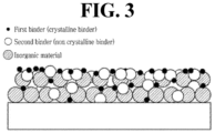
- the separator further includes an organic/inorganic composite coating layer disposed on at least one surface of the separator substrate, in which the organic/inorganic composite coating layer includes a crystalline binder and an amorphous binder.
- the lithium secondary battery further includes an electrolyte, and the crystalline binder and the amorphous binder each independently have a concentration gradient in a thickness direction of the organic/inorganic composite coating layer.
- the organic/inorganic composite coating layer may include a first portion adjacent to the separator substrate and a second portion opposite to the first portion, and the concentration of the crystalline binder in the second portion is higher than the concentration of the crystalline binder in the first portion.
- the polyolefin separator provided in the lithium secondary battery according to the present disclosure has a polyolefin resin polydispersity index (PDI), an average pore size, and a maximum pore size which are controlled to fall within predetermined ranges, and the separator has a strain and recovery rate that are controlled not to be higher than predetermined values. Therefore, the separator has improved compression resistance.
- PDI polyolefin resin polydispersity index
- an average pore size an average pore size
- a maximum pore size which are controlled to fall within predetermined ranges
- the separator has a strain and recovery rate that are controlled not to be higher than predetermined values. Therefore, the separator has improved compression resistance.
- the thickness reduction rate of the separator or the damage to the separator due to the pressure applied is low. Therefore, the Hi-pot defects are reduced, and the capacity retention rate is improved. In addition, the process speed can be increased, resulting in improvement in processability.
- the separator has a porous property having multiple pores, and the separator serves as a porous ion-conducting barrier that prevents an anode and a cathode from being electrically connected and allows transmission of ions, in a lithium secondary battery.
- the characteristic "having pores” herein means that a gas-phase and/or liquid-phase fluid is passable from one side to the other side of an object through pores formed in the object and through a structure connecting the pores.
- a polyolefin separator can be interpreted as a separator itself or a component of a separator. Accordingly, the polyolefin separator described in the present disclosure may further include an additional layer on at least one surface of a separator substrate if necessary in terms of material or function. According to one embodiment of the present disclosure, the separator may have an organic/inorganic composite coating layer including inorganic particles and/or binder resin on at least one side or both sides of the porous substrate.
- a lithium secondary battery uses lithium ions as an ion conductor.
- the lithium secondary battery include, but are not limited to, a non-aqueous electrolyte secondary battery including a liquid electrolyte, an all-solid-state battery including a solid electrolyte, a lithium polymer battery including a gel-type polymer electrolyte, and a lithium metal battery using a lithium metal as an anode.
- a lithium secondary battery according to the present disclosure includes an anode, a cathode, and a separator interposed between the anode and the cathode, in which
- the anode includes a Si-based anode active material.
- the Si-based anode active material may be a material including at least one kind of material selected from the group consisting of Si, SiO, and Si alloys but may not be limited thereto.
- the anode may further include 10% to 90% by weight of another anode active material such as graphite, with respect to the total weight of the anode active materials.
- Si-based anode active materials such as Si, SiO, and Si alloys are anode active materials that are being researched and developed in consideration of capacity.
- Si-based anode active materials have a greater granularity, roughness, and hardness than graphite anode active materials, thereby causing local damage to the separator when being laminated with the separator.
- the present disclosure applies a compression-resistant polyolefin-based separator having the characteristics described above.
- the polyolefin separator according to the present disclosure is made using a polyolefin resin as a base resin.
- the polyolefin-based resin include, but are not limited to, polyethylene, polypropylene, polypentene, and the like.
- the porous separator, i.e., separator having multiple pores, made of such a polyolefin resin as a base resin is advantageous in terms of imparting a shutdown function at appropriate temperatures. Particularly, when polyethylene and polypropylene are both included as the polyolefin resin, both the shutdown characteristic and physical properties such as mechanical strength can be improved.
- the polyolefin resin may have a weight average molecular weight of 500,000 to 1,500,000 g/mol.
- the weight average molecular weight of the polyolefin resin is calculated by adding the weight average molecular weights while applying the content ratio of each polyolefin resin.
- filler particles may be included.
- the filler particles may be included to serve as a pressure barrier so that the thickness, pore size, and porosity of the separator substrate are not excessively reduced by a high pressure applied in the lamination process described below.
- the filler particles may include organic filler particles or inorganic filler particles having a predetermined particle size. The composition of the filler particles is not limited if so long as exhibits a strength equal to or larger than the strength of the polyolefin resin.
- the polydispersity index (PDI) of the polyolefin resin is 2.5 to 4.2, the average pore size of the pores is 20 to 40 nm, and the maximum pore size of the pores is 50 nm or less. That is, in the present disclosure, the polydispersity index of the polyolefin resin is low, and the average pore size and the maximum pore size are small. Compression resistance is improved when these ranges are satisfied at the same time.
- the polydispersity index is less than 2.5, there is a problem that the processability decreases and the film uniformity decreases.
- the polydispersity index exceeds 4.2 there is a problem that the compression resistance decreases.
- the average pore size of the pores is smaller than 20 nm, the air permeability decreases, and the small pores are clogged with the by-products produced during battery charging and discharging.
- the average pore size exceeds 40 nm, the thickness of the separator is not uniform, thickness change occurs, and the compression resistance of the separator decreases due to local thickness changes.
- the maximum pore size of the pores exceeds 50 nm, there is a problem that the compression resistance decreases.
- the size of the pores may be calculated from the pore size distribution measured using a capillary flow porometer. For example, first, the separator to be measured is wetted with a wetting agent such as a Galwick solution, and then the air pressure on one side of the substrate is gradually increased. At this time, when the applied air pressure is greater than the capillary attraction of the wetting agent being present in the pores, the wetting agent in the pores is pushed out. The pore sizes and distribution are measured from the air pressure and flow rate at the moment at which the wetting agent is pushed out of the pores. In this way, the average pore size and the maximum pore size can be determined.
- a wetting agent such as a Galwick solution
- the polydispersity index (PDI) of the polyolefin resin may be in the range of from 2.5 to 4.0 and more specifically the range of from 2.6 to 3.9.
- the average pore size of the pores may be in the range of from 20 to 39 nm, more specifically the range of from 21 to 38 nm, and most specifically the range of from 22.2 to 36.1 nm.
- the maximum pore size of the pores may be 48 nm or less and more specifically 46 nm or less.
- the separator substrate has a strain of 25% or less when a tensile stress of 15 MPa is applied at 60°C for 60 seconds and a recovery time of 200 seconds or less until reaching a recovery rate of 70% when a tensile stress of 2 MPa is applied at 70°C for 180 seconds and then removed.
- the compression resistance of the separator is reduced after the separator is laminated with the Si-based anode.
- the polyolefin separator substrate has characteristics in which
- the separator substrate has a strain of 23% or less when a tensile strain of 15 MPa is applied at 60°C for 60 seconds and a recovery time of 190 seconds or less until reaching a recovery rate of 70% when a tensile stress of 2 MPa is applied at 70°C for 180 seconds and then removed,
- the separator substrate has a strain of 21% or less when a tensile stress of 15 MPa is applied at 60°C for 60 seconds and a recovery time of 180 seconds or less until reaching a recovery rate of 70% when a tensile stress of 2 MPa is applied at 70°C for 180 seconds and then removed, and
- the separator substrate has a strain of 20.1% or less when a tensile stress of 15 MPa is applied at 60°C for 60 seconds and a recovery time of 178 seconds or less until reaching a recovery rate of 70% when a tensile stress of 2 MPa is applied at 70°C for 180 seconds and then removed.
- the polyolefin separator substrate described above may be prepared by a method described below, but is not limited thereto.
- the separator may be prepared by kneading a polyolefin resin with a diluent at a high temperature to form a single phase, performing phase separation into the polymer material and the diluent during a cooling process, and performing elongation and thermal fixing treatment (wet process).
- the polyolefin separator may include a core portion made of a mixture of polyethylene and polypropylene and a polyethylene skin portion laminated on both sides of the core portion.
- the polyolefin separator is not limited thereto.
- the average pore size and maximum pore size of the pores of the separator substrate can be easily controlled by adjusting the mixing ratio of the diluent, elongation magnification, and heat treatment temperature to fall within the ranges of the present disclosure.
- the polyolefin separator substrate prepared by the method described above has a thickness of 5 ⁇ m to 30 ⁇ m.
- the separator may further include an organic/inorganic composite coating layer formed on at least one surface of the polyolefin separator substrate.
- the organic/inorganic composite coating layer includes a binder resin and inorganic particles and has porous properties.
- the binder resin and inorganic particles of the organic/inorganic composite coating layer may be included in a ratio of 1:99 to 30:70 by weight. The ratio may be appropriately adjusted within the range. For example, based on a sum of the binder resin and the inorganic particles 100% by weight, the binder resin may be 1% by weight or more, 5% by weight or more, or 10% by weight or more, and the inorganic particles may be 80% by weight or more, 85% by weight or more, 90% by weight or more, or 95% by weight or more.
- the organic/inorganic composite coating layer may be formed such that the inorganic particles are bonded by the binder resin and integrated into the layer.
- the pores in the organic/inorganic composite coating layer are caused by an interstitial volume that is an empty space between the inorganic particles.
- the porosity of the organic/inorganic composite coating layer and the porosity of the heat resistant layer may be 30% to 70% by volume.
- the porosity is 70% by volume or less, the mechanical properties may be sufficient to withstand the conditions of the press process during bonding to the electrode.
- the porosity level is suitable for securing the adhesive strength.
- the porosity is 30% by volume or more, it is advantageous in terms of ion permeability.
- the thickness of the organic/inorganic composite coating layer may be in the range of from 1 ⁇ m to 20 ⁇ m on either side of the separator substrate.
- the thickness of the organic/inorganic composite coating layer is not particularly limited thereto. The thickness can be adjusted to fall within a suitable range by those skilled in the art, taking heat resistance or electrical resistance into account.
- a non-limiting example of the binder resin usable for the organic/inorganic composite coating layer may be any one polymer resin or a mixture of two or more kinds selected from the group consisting of polyvinylidene fluoride-co-hexafluoropropylene, polyvinylidene fluoride-co-trichloroethylene, polymethylmethacrylate, polybutylacrylate, polyacrylonitrile, polyvinylpyrrolidone, polyvinylacetate, polyethylene-co-vinyl acetate, polyethylene oxide, polyarylate, cyanoethylpullulan, cyanoethylpolyvinylalcohol, cyanoethylcellulose, cyanoethylsucrose, pullulan, and carboxyl methyl cellulose.
- the inorganic particles that can be used in the organic/inorganic composite coating layer are not particularly limited as long as they are electrochemically stable. That is, the inorganic particles used in the present disclosure are not particularly limited unless an oxidation and/or reduction reaction occurs within an operating voltage range (for example, 0 to 5 V for the case of Li/Li + ) of an electrochemical element.
- an operating voltage range for example, 0 to 5 V for the case of Li/Li +
- Non-limiting examples of the inorganic particle include BaTiO 3 , Pb(Zr,Ti)O 3 (PZT), b 1-x La x Zr i-y Ti y O a (PLZT, 0 ⁇ x ⁇ 1, 0 ⁇ y ⁇ 1), Pb (Mg 1/3 Nb 2/3 )O 3 -PbTiO 3 (PMN-PT), hafnia (HfO 2 ), SrTiO 3 , SnO 2 , CeO 2 , MgO, Mg(OH) 2 , NiO, CaO, ZnO, ZrO 2 , SiO 2 , Y 2 O 3 , Al 2 O 3 , SiC, Al(OH) 3 , TiO 2 , aluminum peroxide, zinc tin hydroxide (ZnSn(OH) 6 ), tin-zinc oxide (Zn 2 SnO 4 , ZnSnO 3 ), antimony trioxide (Sb 2 O 3 ), anti
- the average diameter D 50 of the inorganic particles is not particularly limited but is preferably in the range of from 0.3 ⁇ m to 1 um to form a uniform coating layer and to obtain a suitable porosity.
- the average diameter D 50 of the inorganic particles is smaller than 0.3 um, the dispersibility of the inorganic particles in the slurry prepared for manufacturing the heat resistant layer may be reduced.
- the average diameter D 50 of the inorganic particles is larger than 1 um, the thickness of the coating layer may be excessively large.
- the organic/inorganic composite coating layer is prepared by a method described below.
- a polymer solution is prepared by dissolving a binder resin in an appropriate organic solvent. It is desirable that the solvent has a similar solubility index to the binder polymer to be used and a low boiling point. This is to facilitate uniform mixing and subsequent solvent removal.
- the usable solvent include acetone, tetrahydrofuran, methylene chloride, chloroform, dimethylformamide, N-methyl-2-pyrrolidone (NMP), cyclohexane, water, or any mixture thereof.
- inorganic particles are added and dispersed in the prepared polymer solution.
- the content ratio of the inorganic particles and the binder is appropriately determined as described above, depending on the thickness of the heat resistant layer to be formed, the pore size, and porosity.
- the prepared slurry of the inorganic particles is applied to at least one surface of the prepared separator substrate and dried.
- the method of applying the slurry to the surface of the separator substrate is not particularly limited to any one method, and a conventional method known in the art can be used. For example, various methods such as dip coating, die coating, roll coating, comma coating, or a combination thereof may be used.
- temperature and time conditions are appropriately set to minimize the occurrence of surface defects of the organic/inorganic composite coating layer.
- the drying may be performed in appropriate conditions using a drying auxiliary device such as a drying oven or hot air.
- the separator includes the organic/inorganic composite porous layer, damage caused by the inorganic particles pressed against the surface of the separator substrate that faces the organic/inorganic composite porous layer during the lamination process can be reduced.
- the crystallinity herein can be expressed as a percentage of the melting enthalpy value measured by differential scanning calorimetry (DSC) measurement with respect to the melting enthalpy value of theoretically perfect crystals (crystallinity 100%).
- the amorphous binder according to the present disclosure means that a binder having a crystallinity of 30% or less, and the crystalline binder means a binder having a crystallinity of more than 30%.
- the separator further includes an organic/inorganic composite coating layer disposed on at least one surface of the separator substrate, in which the organic/inorganic composite coating layer includes a crystalline binder and an amorphous binder.
- the organic/inorganic composite coating layer includes a crystalline binder and an amorphous binder, when an electrolyte solution is present, the adhesion (wet adhesion) of the organic/inorganic composite coating layer to the electrode is secured by the crystalline binder.
- a crystalline binder and an amorphous binder may be randomly distributed on the surface of the separator substrate.
- an amorphous binder having a relatively low glass transition temperature Tg and a relatively large surface area may be deformed due to the temperature and pressure during the bonding and thus may be present on the surface in a larger amount, resulting in an increase in a dry adhesion force with the electrode.
- the amorphous binder having a high solubility to the electrolyte and high flowability may swell and may move into the organic/inorganic composite coating layer or into the electrode.
- a polymer binder that is being amorphous can more expand than to a binder with high crystallinity.
- the lithium secondary battery further includes an electrolyte
- the crystalline binder and the amorphous binder each independently have a concentration gradient in a thickness direction of the organic/inorganic composite coating layer.
- the slurry may be applied to at least one surface of the separator substrate, and the separator substrate may then be transferred to a heating zone so that the slurry can be dried to form an organic/inorganic composite coating layer.
- the slurry-applied separator substrate may be dried while moving through the heating zone heated to a predetermined temperature at a predetermined speed to form a separator with an organic/inorganic composite coating layer.
- the heating temperature of the heating zone may be in the range of from 45°C to 65°C.
- the porous separator substrate may move through the heating zone at a speed of 25 to 150 m/min and specifically a speed of 40 to 60 m/min.
- the drying conditions of the organic/inorganic composite coating layer may be determined depending on morphological differences between the binder and the inorganic particles. The drying conditions may determine the concentration gradient of each of the binder and the inorganic particles distributed in the thickness direction of the coating layer.
- the organic/inorganic composite coating layer may include a first portion adjacent to the separator substrate and a second portion opposite to the first portion.
- the concentration of the crystalline binder in the second portion may be higher than the concentration of the crystalline binder in the first portion.
- the first portion adjacent to the separator substrate may be relatively close to the separator substrate with respect to a mid-surface of the organic/inorganic composite coating layer cut in a plane direction.
- the first portion may be in contact with the separator substrate.
- the second portion may be closer to the electrode than the first portion with respect to a mid-surface of the organic/inorganic composite coating layer cut in a plane direction.
- the second portion may be in contact with the electrode.
- the average thickness of the first portion may be in the range of from 0.1 to 10 ⁇ m, 0.1 to 5 ⁇ m, 0.1 to 1.5 ⁇ m, 0.1 to 1.0 ⁇ m, 0.1 to 0.5 ⁇ m, or 0.1 to 0.3 um.
- the average thickness of the second portion may be the same as the average thickness of the first portion.
- the crystalline binder and the amorphous binder may each independently include an aqueous emulsion type binder.
- the crystalline binder may be a polyvinylidenefluoride-based binder and the amorphous binder may be an acrylate-based binder.
- the crystalline binder may be one or more kinds selected from the group consisting of polyvinylidene fluoride, polyhexafluoropropylene, polytetrafluoroethylene, polyvinylidene fluoride-hexafluoropropylene (PVDF-HFP), polyvinylidene fluoride-trichloroethylene (PVDF-TCE), and polyvinylidene fluoride-chlorotrifluoroethylene (PVDF-CTFE) . More particularly, the crystalline binder may be a copolymer comprising polyvinylidene fluoride.
- the crystalline binder may have an average particle size D 50 in the range of from 200 nm or more and preferably the range of from 200 nm to 350 nm.
- the weight average molecular weight (M w ) of the crystalline binder may be in the range of from 10,000 to 10,000,000 g/mol.
- the density of the crystalline binder may be in the range of from 1.1 to 1.5 g/cm 3 .
- the crystalline binder may have a glass transition temperature in the range of from 80°C to 200°C, the range of from 80°C to 150°C, the range of from 110°C to 145°C, and the range of from 80°C to 150°C.
- the crystalline binder may exhibit high oxidation resistance to the electrolyte.
- the amorphous binder may include an acrylate-based polymer and specifically may be a copolymer including acrylate as a monomer.
- the amorphous binder may further include one or more binder materials selected from the group consisting of styrene-butadiene rubber, nitrile-butadiene rubber, acrylonitrile-butadiene rubber, and acrylonitrile-butadienestyrene rubber.
- the amorphous binder may have an average particle size D 50 of 350 nm or greater.
- the average particle size D 50 may be in the range of from 350 nm to 500 nm and more preferably the range of from 350 nm to 450 nm.
- the average particle size of the amorphous binder exceeds 500 nm, the mobility toward the interface between the electrode and the coating layer is reduced when an electrolyte is not present, and the adhesion between the electrode and the separator is reduced so that it is difficult to make an electrode assembly.
- the number of binder particles is reduced for the same binder content, the number of contact points between the adjacent inorganic particles is reduced. For this reason, the likelihood of detachment of the inorganic material increases, the interstitial volume decreases, and the electrical resistance decreases.
- the amorphous binder has a larger average particle size D 50 than the crystalline binder.
- the amorphous binder has a larger contact area with the electrode than the crystalline binder, thereby providing better dry adhesion.
- the weight average molecular weight of the amorphous binder may be in the range of from 10,000 to 10,000,000 g/mol.
- the density of the amorphous binder may be in the range of from 0.5 to 1.1 g/cm 3 .
- the amorphous binder may have a glass transition temperature in the range of 40°C or higher, preferably the range of from 45°C to 60°C, and more preferably the range of from 48°C to 60°C.
- acrylic binder particles having a relatively small particle size of 100 to 150 nm were used.
- the acrylic-based binder particles include a diene-based butadiene rubber and have a low glass transition temperature. Due to the low glass transition temperature and the presence of double bonds, the acrylic-based binder particles react with an electrolyte, thereby generating gas.
- the amorphous binder may use a copolymer generated by co-polymerization of acrylic monomer and styrene and having an increased glass transition temperature rather than using an acrylic binder having a glass transition temperature lower than 0°C, thereby preventing a side reaction with an electrolyte.
- the glass transition temperature is in the range described above, the amorphous binder maintains its shape even during the primary drying of the coating layer and exhibits dry adhesion with the electrode.
- the crystalline binder may have a similar characteristic to a binder used for a cathode, and the amorphous binder may have a similar characteristic to a binder used for an anode.
- the cathode may use a polyvinylidenefluoride-based homopolymer having a crystallinity of 95% or higher, and for example, Homo PVDF being usable as a crystalline binder may be included a cathode mixture.
- the anode may use an amorphous acrylic binder of an aqueous emulsion type, and the amorphous acrylic binder may be included in an anode mixture.
- the adhesion between the anode and the separator and between the cathode and the separator can be improved.
- the same binder may be used for the coating layer and the anode and cathode corresponding to the coating layer.
- the crystalline binder may have the same polymer backbone as the binder used for the cathode, and the amorphous binder may have the same polymer backbone as the binder used for the anode.
- the binder that can be used for the anode or the cathode may be a homopolymer of PVdF
- the binder used for the separator may be a PVdF-HFP binder having an HFP substitution rate of 10%.
- the weight ratio of the crystalline binder and the amorphous binder may be in the range of from 1:9 to 9:1, and more particularly from the range of from 3:7 to 7:3.
- the weight ratio of the crystalline binder and the amorphous binder falls within the numerical range described above, with respect to the total weight of the crystalline binder and the amorphous binder, both of the dry adhesion that is an adhesion force when an electrolyte is not present and the wet adhesion that is an adhesion force when an electrolyte is present are good.
- the wet adhesion of the separator to the electrode may be in the range of 10 to 15 gf/20 mm.
- the wet adhesion of the separator to the electrode may be measured by: cutting each of the electrode and the separator into fractions with a predetermined size, placing each fraction in a pouch, and injecting an electrolyte into the pouch; pressing the electrolyte-containing pouch to prepare a specimen for measuring the wet adhesion; and performing a 90° peel test using Instron's UTM equipment at a speed of 200 mm/min to measure the adhesion of the separator to the electrode.
- the separator prepared by the method described above is placed between an anode containing an Si-based anode active material and a cathode, heat and/or pressure is applied to the stacked structure so that the electrodes and the separator are bonded.
- This process is called a lamination process by which an electrode assembly is formed.
- the lamination process can be performed using a roll pressing device including a pair of pressing rollers. That is, the anode, the separator, and the cathode are sequentially stacked, and the stacked structure is inserted between the pressing rollers to achieve interlayer bonding.
- the lamination process may be performed by hot pressing.
- the anode may include an anode current collector and an anode active material layer on at least one surface of the anode current collector.
- the anode active material layer includes a Si-based anode active material, a binder resin, and optionally a conductive material.
- the Si-based anode active material may be used alone or may be used in combination with a carbon-based anode active material such as graphite.
- the cathode includes a cathode current collector and a cathode active material layer provided on at least one surface of the cathode current collector.
- the cathode active material layer includes a cathode active material, a conductive material, and a binder resin.
- the conductive material may be one type or a mixture of two or more types selected from the group consisting of graphite, carbon black, carbon fiber or metal fiber, metal powders, conductive whiskers, conductive metal oxides, activated carbon, and polyphenylene derivatives. More specifically, the conductive material may be one type or a mixture of two or more types selected from the group consisting of natural graphite, synthetic graphite, super-p, acetylene black, ketjen black, channel black, furnace black, lamp black, thermal black, denka black, aluminum powder, nickel powder, zinc oxide, potassium titanium, and titanium oxide.
- binder resin a polymer commonly used for electrodes in the art may be used.
- binder resins include, but are not limited to, polyvinylidene fluoride-co-hexafluoropropylene, polyvinylidene fluoride-cotrichloroethylene, polymethylmethacrylate, polyethylhexyl acrylate, polybutylacrylate, polyacrylonitrile, polyvinylpyrrolidone, polyvinylacetate, polyethylene-co-vinyl acetate, polyethylene oxide, polyarylate, cellulose acetate, cellulose acetate butyrate, cellulose acetatepropionate, cyanoethylpullulan, cyanoethylpolyvinylalcohol, cyanoethylcellulose, cyanoethylsucrose, pullulan, carboxyl methyl cellulose, and the like.
- the prepared electrode assembly is loaded into an appropriate case, and an electrolyte is injected into the case to produce a battery cell.
- the electrolyte comprises a salt having the structure "A + B - " wherein A + comprises an alkali metal cation such as Li + , Na + , K + , or a combination thereof, and B - comprises an anion such as PF 6 - , BF 4 - , Cl - , Br - , I-, ClO 4 - , AsF 6 - , CH 3 CO 2 - , CF 3 SO 3 - , N(CF 3 SO 2 ) 2 - , C(CF 2 SO 2 ) 3 - or a combination thereof.
- a + comprises an alkali metal cation such as Li + , Na + , K + , or a combination thereof
- B - comprises an anion such as PF 6 - , BF 4 - , Cl - , Br - , I-, ClO 4 - , AsF 6 - , CH 3 CO 2 - , CF 3 SO 3 - , N(CF
- the salt may be dissolved or dissociated in an organic solvent composed of one type or a mixture of two or more types selected from propylene carbonate (PC), ethylene carbonate (EC), diethylcarbonate (DEC), dimethylcarbonate (DMC), dipropylcarbonate (DPC), dimethylsulfoxide, acetonitrile, dimethoxyethane, diethoxyethane, tetrahydrofuran, N-methyl-2-pyrrolidone (NMP), ethylmethylcarbonate (EMC), and gamma butyrolactone ( ⁇ -butyrolactone), but is not limited thereto.
- PC propylene carbonate
- EC ethylene carbonate
- DEC diethylcarbonate
- DMC dimethylcarbonate
- DPC dipropylcarbonate
- dimethylsulfoxide acetonitrile, dimethoxyethane, diethoxyethane, tetrahydrofuran
- NMP N-methyl-2-pyr
- the present disclosure provides a battery module including a battery including the electrode assembly as a unit cell, a battery pack including the battery module, and a device including the battery pack as a power source.
- the device include: power tools driven by a battery-powered motor; electric vehicles including an electric vehicle (EV), a hybrid electric vehicle (HEV), and a plug-in hybrid electric vehicle (PHEV); and electric two-wheeled vehicles including an electric bike (E-bike), an electric scooter (E-scooter), an electric golf cart, a power storage system, etc., but the examples are not limited thereto.
- Step of preparing a separator
- Polyethylene weight average molecular weight of 900,000 g/mol
- polypropylene weight average molecular weight of 350,000 g/mol
- Polyethylene resin weight average molecular weight of 900,000 g/mol
- a polyolefin separator substrate total thickness: about 9 ⁇ m, core portion thickness: 7 ⁇ m, and total thickness of both skin portions: 2 ⁇ m
- Step of preparing a composition for forming an organic/inorganic composite coating layer Step of preparing a composition for forming an organic/inorganic composite coating layer:
- An alumina product (Sumitomo, AES11) having an average particle size (D 50 ) of 500 nm, a density of 4 g/cm 3 , an aspect ratio of 1.3, and a BET specific surface area of 8 m 2 /g was used for inorganic particles.
- a fluorine-based water dispersion emulsion (Arkema, Aquatec9530, 30% by weight of solids) having an average particle size (D 50 ) of 200 nm was used as a crystalline polymer.
- Step of forming an organic/inorganic coating layer on each side of a separator substrate Step of forming an organic/inorganic coating layer on each side of a separator substrate:
- the organic/inorganic composite coating layer composition was applied on both surfaces of the polyolefin separator substrate using a bar coater.
- the polyolefin separator substrate on both surfaces of which the organic/inorganic composite coating layer composition was applied was moved at a speed of 40 m/min, introduced into seven heating zones having temperatures of 65°C, 65°C, 60°C, 55°C, 50°C, 45°C, and 45°C, respectively, and dried for 2 to 3 minutes to form organic/inorganic composite coating layers (each layer having a thickness of 3 pm) .
- a separator was obtained.
- a cathode active material LiNi 0.8 Mn 0.1 Co 0.1 O 2
- a conductive material carbon black
- a binder resin mixture of PVDF-HFP and PVDF
- a Si-based anode active material SiO 20%, graphite 80%
- a conductive material carbon black
- a dispersant a binder resin
- a binder resin mixture of PVDF-HFP and PVDF
- anode active material slurry in which the concentration of components other than water was 50% by weight.
- the slurry was applied to a surface of a copper thin film (10 ⁇ m thick) and dried to produce an anode having an anode active material layer (120 ⁇ m thick).
- Electrode assemblies were obtained by interposing one of the separators of the examples and the comparative examples between the cathode and the anode and by performing a lamination process.
- the lamination process was carried out using a hot press for 10 seconds under conditions of 70°C and 5.2 MPa.
- Example 2 Cells were manufactured in the same manner as in Example 1 except that the elongation temperature was adjusted to 120°C. and the thermal fixing temperature was adjusted to 115°C when manufacturing separators.
- Example 2 Cells were manufactured in the same manner as in Example 1 except that the thermal fixing temperature was adjusted to 115°C when manufacturing separators.
- Cells were manufactured in the same manner as in Example 1 except that a mixture of polyethylene (average molecular weight of 900,000 g/mol) and polypropylene (average molecular weight of 350,000 g/mol) in a weight ratio of 97:3 was used as a resin to form the skin portion to prepare the separator, and the elongation temperature was adjusted to 120°C.
- a mixture of polyethylene (average molecular weight of 900,000 g/mol) and polypropylene (average molecular weight of 350,000 g/mol) in a weight ratio of 97:3 was used as a resin to form the skin portion to prepare the separator, and the elongation temperature was adjusted to 120°C.
- Cells were manufactured in the same manner as in Example 1 except that a mixture of polyethylene (average molecular weight of 900,000 g/mol) and polypropylene (average molecular weight of 350,000 g/mol) in a weight ratio of 97:3 was used as a resin to form the skin portion to prepare the separators, and the thermal fixing temperature was adjusted to 115°C.
- Cells were manufactured in the same manner as in Example 1 except that a mixture of polyethylene (average molecular weight of 900,000 g/mol) and polypropylene (average molecular weight of 350,000 g/mol) in a weight ratio of 97:3 was used as a resin to form the skin portion to prepare the separators.
- a mixture of polyethylene (average molecular weight of 900,000 g/mol) and polypropylene (average molecular weight of 350,000 g/mol) in a weight ratio of 97:3 was used as a resin to form the skin portion to prepare the separators.
- Cells were manufactured in the same manner as in Example 1 except that a mixture of polyethylene (average molecular weight of 900,000 g/mol) and polypropylene (average molecular weight of 350,000 g/mol) in a weight ratio of 97:3 was used as a resin to form the skin portion to prepare the separators, the elongation temperature was adjusted to 120°C, and the thermal fixing temperature was adjusted to 115°C.
- the PDI (weight average molecular weight) / (number average molecular weight)
- the values of the weight average molecular weight and the number average molecular weight were obtained through gel permeation chromatography (GPC) analysis for a separator cut to have a predetermined size.
- the average pore size and maximum pore size were measured by a pore size distribution using a capillary flow porometer (CFP) method.
- Strain was measured by applying a stress of 15 MPa at 60°C for 60 seconds through dynamic mechanical analysis creep evaluation.
- a separator was prepared in the same manner as Example 1, except that the weight ratio was changed from 79:18:2:1 (inorganic particles: crystalline polymer: amorphous polymer: dispersant) to 79:20:1 (inorganic particles: amorphous polymer: dispersant).
- Example 1 The cathode of Example 1 and the separators manufactured by the methods according to Examples 1 and 4 were cut to have a width of 20 mm, the fraction was placed in a pouch, and the pouch was injected with a carbonate-based electrolyte solution.
- Two separate separator-electrode assembly samples for measuring wet adhesion were prepared by pressing the pouch containing the electrolyte solution under conditions of 5 kgf, 70°C, and 4 minutes.
- To measure the adhesion of the separator to the cathode a 90° peel test was performed using Instron's UTM instrument at a speed of 200 mm/min.
- [Table 3] Classification Example 1 Example 4 Binder in organic/inorganic composite coating Crystalline binder and amorphous binder Amorphous binder layer Wet adhesion (gf/20 mm) 10 3
Landscapes
- Chemical & Material Sciences (AREA)
- Chemical Kinetics & Catalysis (AREA)
- Electrochemistry (AREA)
- General Chemical & Material Sciences (AREA)
- Inorganic Chemistry (AREA)
- Engineering & Computer Science (AREA)
- Materials Engineering (AREA)
- Manufacturing & Machinery (AREA)
- Composite Materials (AREA)
- Cell Separators (AREA)
- Battery Electrode And Active Subsutance (AREA)
Priority Applications (1)
| Application Number | Priority Date | Filing Date | Title |
|---|---|---|---|
| EP26165991.6A EP4738594A2 (de) | 2022-06-14 | 2023-03-31 | Lithiumsekundärbatterie mit negativem elektrodenaktivmaterial auf si-basis |
Applications Claiming Priority (3)
| Application Number | Priority Date | Filing Date | Title |
|---|---|---|---|
| KR20220072073 | 2022-06-14 | ||
| KR1020230040702A KR102618427B1 (ko) | 2022-06-14 | 2023-03-28 | Si계 음극 활물질을 구비하는 리튬 이차전지 |
| PCT/KR2023/004414 WO2023243833A1 (ko) | 2022-06-14 | 2023-03-31 | Si계 음극 활물질을 구비하는 리튬 이차전지 |
Related Child Applications (2)
| Application Number | Title | Priority Date | Filing Date |
|---|---|---|---|
| EP26165991.6A Division-Into EP4738594A2 (de) | 2022-06-14 | 2023-03-31 | Lithiumsekundärbatterie mit negativem elektrodenaktivmaterial auf si-basis |
| EP26165991.6A Division EP4738594A2 (de) | 2022-06-14 | 2023-03-31 | Lithiumsekundärbatterie mit negativem elektrodenaktivmaterial auf si-basis |
Publications (3)
| Publication Number | Publication Date |
|---|---|
| EP4404366A1 true EP4404366A1 (de) | 2024-07-24 |
| EP4404366A4 EP4404366A4 (de) | 2025-03-26 |
| EP4404366B1 EP4404366B1 (de) | 2026-04-29 |
Family
ID=89191372
Family Applications (2)
| Application Number | Title | Priority Date | Filing Date |
|---|---|---|---|
| EP26165991.6A Pending EP4738594A2 (de) | 2022-06-14 | 2023-03-31 | Lithiumsekundärbatterie mit negativem elektrodenaktivmaterial auf si-basis |
| EP23824060.0A Active EP4404366B1 (de) | 2022-06-14 | 2023-03-31 | Lithiumsekundärbatterie mit negativem elektrodenaktivmaterial auf si-basis |
Family Applications Before (1)
| Application Number | Title | Priority Date | Filing Date |
|---|---|---|---|
| EP26165991.6A Pending EP4738594A2 (de) | 2022-06-14 | 2023-03-31 | Lithiumsekundärbatterie mit negativem elektrodenaktivmaterial auf si-basis |
Country Status (6)
| Country | Link |
|---|---|
| US (1) | US12548854B2 (de) |
| EP (2) | EP4738594A2 (de) |
| JP (1) | JP2025519299A (de) |
| KR (1) | KR102713783B1 (de) |
| CN (2) | CN117981157B (de) |
| WO (1) | WO2023243833A1 (de) |
Family Cites Families (26)
| Publication number | Priority date | Publication date | Assignee | Title |
|---|---|---|---|---|
| CA2101833A1 (en) | 1992-12-14 | 1994-06-15 | Kimberly-Clark Worldwide, Inc. | Stretchable meltblown fabric with barrier properties |
| JP3508510B2 (ja) * | 1997-10-24 | 2004-03-22 | 宇部興産株式会社 | 積層多孔質フイルム及びその製法 |
| JP5202816B2 (ja) | 2006-04-07 | 2013-06-05 | 東レバッテリーセパレータフィルム株式会社 | ポリオレフィン微多孔膜及びその製造方法 |
| US7981536B2 (en) * | 2006-08-31 | 2011-07-19 | Toray Tonen Specialty Separator Godo Kaisha | Microporous membrane, battery separator and battery |
| KR100727248B1 (ko) * | 2007-02-05 | 2007-06-11 | 주식회사 엘지화학 | 다공성 활성층이 코팅된 유기/무기 복합 분리막 및 이를구비한 전기화학소자 |
| US8273279B2 (en) | 2007-09-28 | 2012-09-25 | Toray Battery Separator Film Co., Ltd. | Microporous polyolefin membrane and manufacturing method |
| US8323821B2 (en) | 2007-11-09 | 2012-12-04 | Toray Battery Separator Film Co., Ltd. | Multi-layer microporous membrane, battery separator and battery |
| WO2009048175A2 (en) | 2007-10-12 | 2009-04-16 | Tonen Chemical Corporation | Microporous membranes and methods for making and using such membranes |
| EP2111912A1 (de) | 2008-04-24 | 2009-10-28 | Tonen Chemical Corporation | Mikroporöse Polyolefinmembran und Herstellungsverfahren dafür |
| EP2111913A1 (de) | 2008-04-24 | 2009-10-28 | Tonen Chemical Corporation | Mikroporöse Membran und Herstellungsverfahren dafür |
| KR101635489B1 (ko) | 2008-09-02 | 2016-07-01 | 도레이 배터리 세퍼레이터 필름 주식회사 | 미세다공성 고분자막, 이 미세다공성 고분자막의 제조방법 및 전지 세퍼레이터 필름으로서의 이 미세다공성 고분자막의 사용 |
| JP5369171B2 (ja) | 2009-03-09 | 2013-12-18 | 旭化成イーマテリアルズ株式会社 | 積層セパレータ及びその製造方法 |
| CN103068892B (zh) | 2010-08-18 | 2014-09-10 | 积水化学工业株式会社 | 丙烯类树脂微孔膜、电池用隔板、电池及丙烯类树脂微孔膜的制造方法 |
| US8771880B2 (en) * | 2011-04-05 | 2014-07-08 | Shin-Etsu Chemical Co., Ltd. | Binder for separator of non-aqueous electrolyte battery comprising 2-cyanoethyl group-containing polymer and separator and battery using the same |
| CN103184013A (zh) | 2011-12-28 | 2013-07-03 | 天津东皋膜技术有限公司 | 具有热压粘合特性的聚乙烯基复合材料微多孔隔膜 |
| JP6927034B2 (ja) | 2015-03-24 | 2021-08-25 | 日本電気株式会社 | リチウムイオン二次電池、およびその製造方法 |
| EP3309879B1 (de) * | 2015-06-12 | 2018-10-03 | LG Chem, Ltd. | Positivelektrodenmischung und sekundärbatterie die diese enthält |
| JP6288216B2 (ja) | 2016-02-09 | 2018-03-07 | 宇部興産株式会社 | ポリオレフィン微多孔膜、蓄電デバイス用セパレータフィルム、及び蓄電デバイス |
| EP3587481B1 (de) | 2017-03-27 | 2021-09-08 | Asahi Kasei Kabushiki Kaisha | Mikroporöse polyolefinmembran und herstellungsverfahren dafür |
| CN116722306A (zh) | 2018-09-25 | 2023-09-08 | 旭化成株式会社 | 高强度分隔件 |
| US12110382B2 (en) | 2019-03-04 | 2024-10-08 | Asahi Kasei Kabushiki Kaisha | Polyolefin microporous membrane |
| CN113614993A (zh) * | 2019-03-28 | 2021-11-05 | 东丽株式会社 | 聚烯烃微多孔膜、二次电池用隔板及二次电池 |
| KR102249890B1 (ko) * | 2019-07-03 | 2021-05-07 | 삼성에스디아이 주식회사 | 이차 전지용 분리막, 이차 전지용 분리막의 제조 방법 및 이를 포함하는 리튬 이차 전지 |
| EP3832770A1 (de) * | 2019-12-06 | 2021-06-09 | W-Scope Korea Co., Ltd. | Vernetzter separator und verfahren zur herstellung davon |
| US20230268615A1 (en) | 2020-09-07 | 2023-08-24 | Lg Energy Solution, Ltd. | Separator for electrochemical device and method for manufacturing the same |
| KR102487676B1 (ko) | 2020-11-24 | 2023-01-13 | (주)이미지스테크놀로지 | 환경 변화에 대한 보상 기능을 구비한 터치 또는 근접성 감지 장치 및 이를 위한 환경 보상 방법 |
-
2023
- 2023-03-31 EP EP26165991.6A patent/EP4738594A2/de active Pending
- 2023-03-31 US US18/690,992 patent/US12548854B2/en active Active
- 2023-03-31 WO PCT/KR2023/004414 patent/WO2023243833A1/ko not_active Ceased
- 2023-03-31 CN CN202380013726.6A patent/CN117981157B/zh active Active
- 2023-03-31 EP EP23824060.0A patent/EP4404366B1/de active Active
- 2023-03-31 JP JP2024518897A patent/JP2025519299A/ja active Pending
- 2023-03-31 CN CN202510966015.1A patent/CN120955306A/zh active Pending
- 2023-12-13 KR KR1020230180759A patent/KR102713783B1/ko active Active
Also Published As
| Publication number | Publication date |
|---|---|
| EP4404366A4 (de) | 2025-03-26 |
| CN117981157A (zh) | 2024-05-03 |
| JP2025519299A (ja) | 2025-06-26 |
| US12548854B2 (en) | 2026-02-10 |
| EP4404366B1 (de) | 2026-04-29 |
| WO2023243833A1 (ko) | 2023-12-21 |
| CN120955306A (zh) | 2025-11-14 |
| KR102713783B1 (ko) | 2024-10-07 |
| EP4738594A2 (de) | 2026-05-06 |
| US20240266679A1 (en) | 2024-08-08 |
| KR20240001083A (ko) | 2024-01-03 |
| CN117981157B (zh) | 2025-08-05 |
Similar Documents
| Publication | Publication Date | Title |
|---|---|---|
| KR102404990B1 (ko) | 전기화학소자용 분리막 및 이를 포함하는 전기화학소자 | |
| EP2693527A1 (de) | Organisches/anorganisches Verbundtrennglied mit einer porösen Aktivbeschichtungsschicht und elektrochemische Einreichung damit | |
| KR102652724B1 (ko) | 이차전지용 분리막 | |
| EP4050720A1 (de) | Abscheider für elektrochemische vorrichtung und elektrochemische vorrichtung damit | |
| KR102830174B1 (ko) | 전기화학소자용 분리막 및 이를 포함하는 전기화학소자 | |
| EP4358270A1 (de) | Verfahren zur herstellung eines lithiumsekundärbatterieseparators, damit hergestellter lithiumsekundärbatterieseparator und lithiumsekundärbatterie damit | |
| EP4346001A1 (de) | Separator für lithiumsekundärbatterie und lithiumsekundärbatterie damit | |
| EP4425680A2 (de) | Belüfter für eine elektrochemische vorrichtung und elektrochemische vorrichtung damit | |
| EP4404366B1 (de) | Lithiumsekundärbatterie mit negativem elektrodenaktivmaterial auf si-basis | |
| KR102618427B1 (ko) | Si계 음극 활물질을 구비하는 리튬 이차전지 | |
| EP4425681A2 (de) | Belüfter für eine elektrochemische vorrichtung, elektrochemische vorrichtung damit und herstellungsverfahren dafür | |
| EP4369503A1 (de) | Verfahren zur herstellung eines separators für eine lithiumsekundärbatterie, damit hergestellter separator für eine lithiumsekundärbatterie und verfahren zur herstellung einer lithiumsekundärbatterie damit | |
| KR102563504B1 (ko) | 전기화학소자용 폴리올레핀 분리막 및 이를 구비한 전기화학소자 | |
| EP4425678A1 (de) | Separator für elektrochemische vorrichtung und elektrochemische vorrichtung damit | |
| US20250337120A1 (en) | Separator for electrochemical device and electrochemical device including the same | |
| EP4517994A1 (de) | Separator für elektrochemische vorrichtung und elektrochemische vorrichtung damit | |
| KR20230171646A (ko) | 고용량의 전극을 구비하는 리튬 이차전지 | |
| EP4246699A1 (de) | Verfahren zur herstellung einer elektrodenanordnung für eine elektrochemische vorrichtung, durch dieses verfahren erhaltene elektrodenanordnung und verfahren zur herstellung einer elektrochemischen vorrichtung | |
| KR20250146296A (ko) | 전기화학소자용 분리막 및 이를 제조하는 방법 | |
| KR20240160757A (ko) | 전기화학소자용 분리막, 이의 제조방법 및 이를 포함하는 전기화학소자 | |
| CN121866676A (zh) | 用于电化学装置的隔板和包括该隔板的电化学装置 | |
| CN120814107A (zh) | 电化学装置用分隔件和包括其的电化学装置 |
Legal Events
| Date | Code | Title | Description |
|---|---|---|---|
| STAA | Information on the status of an ep patent application or granted ep patent |
Free format text: STATUS: THE INTERNATIONAL PUBLICATION HAS BEEN MADE |
|
| PUAI | Public reference made under article 153(3) epc to a published international application that has entered the european phase |
Free format text: ORIGINAL CODE: 0009012 |
|
| STAA | Information on the status of an ep patent application or granted ep patent |
Free format text: STATUS: REQUEST FOR EXAMINATION WAS MADE |
|
| 17P | Request for examination filed |
Effective date: 20240419 |
|
| AK | Designated contracting states |
Kind code of ref document: A1 Designated state(s): AL AT BE BG CH CY CZ DE DK EE ES FI FR GB GR HR HU IE IS IT LI LT LU LV MC ME MK MT NL NO PL PT RO RS SE SI SK SM TR |
|
| A4 | Supplementary search report drawn up and despatched |
Effective date: 20250224 |
|
| RIC1 | Information provided on ipc code assigned before grant |
Ipc: H01M 4/134 20100101ALI20250218BHEP Ipc: H01M 50/491 20210101ALI20250218BHEP Ipc: H01M 50/451 20210101ALI20250218BHEP Ipc: H01M 4/02 20060101ALI20250218BHEP Ipc: H01M 4/587 20100101ALI20250218BHEP Ipc: H01M 4/36 20060101ALI20250218BHEP Ipc: H01M 10/052 20100101ALI20250218BHEP Ipc: H01M 4/48 20100101ALI20250218BHEP Ipc: H01M 4/38 20060101ALI20250218BHEP Ipc: H01M 50/449 20210101ALI20250218BHEP Ipc: H01M 50/494 20210101ALI20250218BHEP Ipc: H01M 50/489 20210101ALI20250218BHEP Ipc: H01M 50/417 20210101AFI20250218BHEP |
|
| DAV | Request for validation of the european patent (deleted) | ||
| DAX | Request for extension of the european patent (deleted) | ||
| GRAP | Despatch of communication of intention to grant a patent |
Free format text: ORIGINAL CODE: EPIDOSNIGR1 |
|
| STAA | Information on the status of an ep patent application or granted ep patent |
Free format text: STATUS: GRANT OF PATENT IS INTENDED |
|
| RIC1 | Information provided on ipc code assigned before grant |
Ipc: H01M 50/417 20210101AFI20251103BHEP Ipc: H01M 4/02 20060101ALI20251103BHEP Ipc: H01M 4/134 20100101ALI20251103BHEP Ipc: H01M 4/36 20060101ALI20251103BHEP Ipc: H01M 4/38 20060101ALI20251103BHEP Ipc: H01M 4/48 20100101ALI20251103BHEP Ipc: H01M 4/587 20100101ALI20251103BHEP Ipc: H01M 10/052 20100101ALI20251103BHEP Ipc: H01M 10/0525 20100101ALI20251103BHEP Ipc: H01M 50/449 20210101ALI20251103BHEP Ipc: H01M 50/451 20210101ALI20251103BHEP Ipc: H01M 50/489 20210101ALI20251103BHEP Ipc: H01M 50/491 20210101ALI20251103BHEP Ipc: H01M 50/494 20210101ALI20251103BHEP |
|
| INTG | Intention to grant announced |
Effective date: 20251121 |
|
| P01 | Opt-out of the competence of the unified patent court (upc) registered |
Free format text: CASE NUMBER: UPC_APP_0000905_4404366/2026 Effective date: 20260112 |
|
| GRAS | Grant fee paid |
Free format text: ORIGINAL CODE: EPIDOSNIGR3 |
|
| GRAA | (expected) grant |
Free format text: ORIGINAL CODE: 0009210 |
|
| STAA | Information on the status of an ep patent application or granted ep patent |
Free format text: STATUS: THE PATENT HAS BEEN GRANTED |
|
| AK | Designated contracting states |
Kind code of ref document: B1 Designated state(s): AL AT BE BG CH CY CZ DE DK EE ES FI FR GB GR HR HU IE IS IT LI LT LU LV MC ME MK MT NL NO PL PT RO RS SE SI SK SM TR |
|
| REG | Reference to a national code |
Ref country code: CH Ref legal event code: F10 Free format text: ST27 STATUS EVENT CODE: U-0-0-F10-F00 (AS PROVIDED BY THE NATIONAL OFFICE) Effective date: 20260429 |