EP4425680A2 - Belüfter für eine elektrochemische vorrichtung und elektrochemische vorrichtung damit - Google Patents
Belüfter für eine elektrochemische vorrichtung und elektrochemische vorrichtung damit Download PDFInfo
- Publication number
- EP4425680A2 EP4425680A2 EP24153077.3A EP24153077A EP4425680A2 EP 4425680 A2 EP4425680 A2 EP 4425680A2 EP 24153077 A EP24153077 A EP 24153077A EP 4425680 A2 EP4425680 A2 EP 4425680A2
- Authority
- EP
- European Patent Office
- Prior art keywords
- less
- separator
- polymer binder
- coating layer
- weight
- Prior art date
- Legal status (The legal status is an assumption and is not a legal conclusion. Google has not performed a legal analysis and makes no representation as to the accuracy of the status listed.)
- Pending
Links
Images

Classifications
-
- H—ELECTRICITY
- H01—ELECTRIC ELEMENTS
- H01M—PROCESSES OR MEANS, e.g. BATTERIES, FOR THE DIRECT CONVERSION OF CHEMICAL ENERGY INTO ELECTRICAL ENERGY
- H01M50/00—Constructional details or processes of manufacture of the non-active parts of electrochemical cells other than fuel cells, e.g. hybrid cells
- H01M50/40—Separators; Membranes; Diaphragms; Spacing elements inside cells
- H01M50/409—Separators, membranes or diaphragms characterised by the material
- H01M50/446—Composite material consisting of a mixture of organic and inorganic materials
-
- H—ELECTRICITY
- H01—ELECTRIC ELEMENTS
- H01M—PROCESSES OR MEANS, e.g. BATTERIES, FOR THE DIRECT CONVERSION OF CHEMICAL ENERGY INTO ELECTRICAL ENERGY
- H01M50/00—Constructional details or processes of manufacture of the non-active parts of electrochemical cells other than fuel cells, e.g. hybrid cells
- H01M50/40—Separators; Membranes; Diaphragms; Spacing elements inside cells
- H01M50/409—Separators, membranes or diaphragms characterised by the material
- H01M50/411—Organic material
- H01M50/414—Synthetic resins, e.g. thermoplastics or thermosetting resins
- H01M50/426—Fluorocarbon polymers
-
- H—ELECTRICITY
- H01—ELECTRIC ELEMENTS
- H01M—PROCESSES OR MEANS, e.g. BATTERIES, FOR THE DIRECT CONVERSION OF CHEMICAL ENERGY INTO ELECTRICAL ENERGY
- H01M50/00—Constructional details or processes of manufacture of the non-active parts of electrochemical cells other than fuel cells, e.g. hybrid cells
- H01M50/40—Separators; Membranes; Diaphragms; Spacing elements inside cells
- H01M50/409—Separators, membranes or diaphragms characterised by the material
- H01M50/431—Inorganic material
-
- H—ELECTRICITY
- H01—ELECTRIC ELEMENTS
- H01M—PROCESSES OR MEANS, e.g. BATTERIES, FOR THE DIRECT CONVERSION OF CHEMICAL ENERGY INTO ELECTRICAL ENERGY
- H01M50/00—Constructional details or processes of manufacture of the non-active parts of electrochemical cells other than fuel cells, e.g. hybrid cells
- H01M50/40—Separators; Membranes; Diaphragms; Spacing elements inside cells
- H01M50/409—Separators, membranes or diaphragms characterised by the material
- H01M50/443—Particulate material
-
- H—ELECTRICITY
- H01—ELECTRIC ELEMENTS
- H01M—PROCESSES OR MEANS, e.g. BATTERIES, FOR THE DIRECT CONVERSION OF CHEMICAL ENERGY INTO ELECTRICAL ENERGY
- H01M50/00—Constructional details or processes of manufacture of the non-active parts of electrochemical cells other than fuel cells, e.g. hybrid cells
- H01M50/40—Separators; Membranes; Diaphragms; Spacing elements inside cells
- H01M50/409—Separators, membranes or diaphragms characterised by the material
- H01M50/449—Separators, membranes or diaphragms characterised by the material having a layered structure
- H01M50/451—Separators, membranes or diaphragms characterised by the material having a layered structure comprising layers of only organic material and layers containing inorganic material
-
- H—ELECTRICITY
- H01—ELECTRIC ELEMENTS
- H01M—PROCESSES OR MEANS, e.g. BATTERIES, FOR THE DIRECT CONVERSION OF CHEMICAL ENERGY INTO ELECTRICAL ENERGY
- H01M50/00—Constructional details or processes of manufacture of the non-active parts of electrochemical cells other than fuel cells, e.g. hybrid cells
- H01M50/40—Separators; Membranes; Diaphragms; Spacing elements inside cells
- H01M50/46—Separators, membranes or diaphragms characterised by their combination with electrodes
- H01M50/461—Separators, membranes or diaphragms characterised by their combination with electrodes with adhesive layers between electrodes and separators
-
- H—ELECTRICITY
- H01—ELECTRIC ELEMENTS
- H01M—PROCESSES OR MEANS, e.g. BATTERIES, FOR THE DIRECT CONVERSION OF CHEMICAL ENERGY INTO ELECTRICAL ENERGY
- H01M50/00—Constructional details or processes of manufacture of the non-active parts of electrochemical cells other than fuel cells, e.g. hybrid cells
- H01M50/40—Separators; Membranes; Diaphragms; Spacing elements inside cells
- H01M50/489—Separators, membranes, diaphragms or spacing elements inside the cells, characterised by their physical properties, e.g. swelling degree, hydrophilicity or shut down properties
-
- H—ELECTRICITY
- H01—ELECTRIC ELEMENTS
- H01M—PROCESSES OR MEANS, e.g. BATTERIES, FOR THE DIRECT CONVERSION OF CHEMICAL ENERGY INTO ELECTRICAL ENERGY
- H01M10/00—Secondary cells; Manufacture thereof
- H01M10/05—Accumulators with non-aqueous electrolyte
- H01M10/052—Li-accumulators
-
- Y—GENERAL TAGGING OF NEW TECHNOLOGICAL DEVELOPMENTS; GENERAL TAGGING OF CROSS-SECTIONAL TECHNOLOGIES SPANNING OVER SEVERAL SECTIONS OF THE IPC; TECHNICAL SUBJECTS COVERED BY FORMER USPC CROSS-REFERENCE ART COLLECTIONS [XRACs] AND DIGESTS
- Y02—TECHNOLOGIES OR APPLICATIONS FOR MITIGATION OR ADAPTATION AGAINST CLIMATE CHANGE
- Y02E—REDUCTION OF GREENHOUSE GAS [GHG] EMISSIONS, RELATED TO ENERGY GENERATION, TRANSMISSION OR DISTRIBUTION
- Y02E60/00—Enabling technologies; Technologies with a potential or indirect contribution to GHG emissions mitigation
- Y02E60/10—Energy storage using batteries
Definitions
- the present disclosure claims the benefit of the filing date of Korean Patent Application No. 10-2023-0026495, filed with the Korean Intellectual Property Office on February 28, 2023 and the benefit of the filing date of Korean Patent Application No. 10-2024-0007842, filed with the Korean Intellectual Property Office on January 18, 2024 , all of which is included in the present disclosure.
- the present disclosure relates to a separator for an electrochemical device and an electrochemical device including the same, and more specifically, to a separator for an electrochemical device which is capable of improving heat resistance by providing an adhesive layer including a polyvinyl acetate-based resin in a coating layer, and reducing the resistance of a battery.
- a separator which includes a polymer substrate having a porous structure located between a cathode and an anode, plays the roles of separating a cathode and an anode, preventing an electrical short circuit between the two electrodes, and allowing electrolytes and ions to pass therethrough.
- the separator itself does not participate in the electrochemical reaction, but physical properties such as wettability to electrolyte, degree of porosity, and thermal contraction rate affect the performance and safety of an electrochemical device.
- an inorganic material may be added to the coating layer to improve mechanical strength of the separator, or an inorganic material or hydrate may be added to the coating layer to improve flame retardancy and heat resistance of a polymer substrate.
- an inorganic material may be added to the coating layer so as to improve mechanical strength of the separator, or an inorganic material or hydrate may be added to the coating layer so as to improve flame retardancy and heat resistance of the polymer substrate.
- the separator may be attached to the electrodes through a lamination process, and a binder resin may be added to the slurry for the coating layer of the separator so as to secure adhesion between the electrodes and the separator.
- PVdF-HFP poly(vinylidene fluoride-co-hexafluoropropylene)
- the separator including a high content of inorganic particles in the coating layer it has excellent heat resistance due to a high content of inorganic materials and enables thinning of the separator.
- separator including a coating layer with a high content of inorganic particles had a problem in that an adhesive layer does not exist on the surface, lamination is impossible in the assembly process of manufacturing batteries.
- An object of the present disclosure is to provide a separator for an electrochemical device overcoming drawbacks of the prior art, especially implementing the viscosity of an electrolyte in a battery at a low level, and improving the performance of the battery and thinning the separator; and an electrochemical device including the same.
- an adhesive layer containing a polyvinyl acetate-based resin is provided in a coating layer, the amount of a binder dissolved in the electrolyte is controlled.
- a separator for an electrochemical device which includes: a porous polymer substrate; a coating layer, wherein the coating layer is provided on at least one surface of the porous polymer substrate; and the coating layer comprises a first polymer binder and inorganic particles; and an adhesive layer, wherein the adhesive layer is provided on the coating layer; and the adhesive layer comprises a second polymer binder, wherein the second polymer binder comprises a polyvinyl acetate-based resin, wherein an amount of the second polymer binder per area of the adhesive layer is greater than 0 g/m 2 and less than 1.5 g/m 2 .
- the area is the area seen from a plane view on the separator, that is from a view perpendicular to the substrate, the coating layer and the adhesive layer.
- the amount of the second polymer binder per area of the adhesive layer may be from 0.1 g/m 2 to 1.4 g/m 2 .
- the content of the inorganic particles in the coating layer may be 90 parts by weight or more based on 100 parts by weight of the coating layer.
- the second polymer binder may be in particulate form.
- the adhesive layer may further comprise a third polymer binder, wherein the third polymer binder comprises a polyvinylidene-based binder.
- the polyvinylidene-based binder may be a copolymer of polyvinylidene fluoride and hexafluoropropylene.
- a weight ratio of the second polymer binder and the third polymer binder in the adhesive layer may be 99:1 to 50:50.
- the thickness of the coating layer may be greater than 0 and 2.0 ⁇ m or less.
- the resistance of the separator may be 0.8 ⁇ or less.
- an electrochemical device comprising a cathode, an anode, a separator, and an electrolyte, wherein the separator is interposed between the cathode and the anode, and is the separator is the separator for an electrochemical device according to any of the first to the ninth embodiments.
- the solubility of the second polymer binder in the electrolyte may be 50 (w/w)% or more and 80 (w/w)% or less at room temperature.
- the separator for an electrochemical device can improve the energy density of the battery by thinning the separator, and by providing an adhesive layer, the coating layer containing a high content of inorganic particles can realize adhesive strength in the process of manufacturing a battery.
- the electrochemical device can maintain the viscosity of the electrolyte at a low level by adjusting the solubility of the polymer binder included in an adhesive layer in the electrolyte, and can maintain the surface resistance of a battery at a low level while improving the ionic conductivity of the battery.
- a material essentially comprising polyethylene comprises the polyethylene in an amount of at least 70 wt% with respect to the total weight of the material.
- a and/or B means “A and B, or A or B”.
- the characteristic of "having pores” means that a target object includes a plurality of pores and allows a gaseous and/or liquid fluid to pass through one side of the object and the other side by a structure connected to one another among the pores.
- the separator has a porous property including a number of pores, and it serves as a porous ion-conducting barrier that blocks the electrical contact between an anode and a cathode in an electrochemical device and allows ions to pass therethrough.
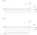
- a separator for an electrochemical device 100 includes: a porous polymer substrate 110, a coating layer 130 and an and hesive layer150.
- the coating layer 130 is provided on, preferably directly on, at least one surface of the porous polymer substrate 110. and the coating layer includes, essentially comprises or consists of a first polymer binder 131 (not shown) and inorganic particles 133 (not shown).
- the adhesive layer 150 is provided on, preferably directly on, the coating layer 130. and the adhesive layer includes, essentially comprises or consists of a second polymer binder 151.
- the second polymer binder comprises, essentially comprises or consists of a polyvinyl acetate (PVAc)-based resin.
- the amount of the second polymer binder 151 per area of the adhesive layer 150 is greater than 0 g/m 2 and equal to or less than 1.5 g/m 2 .
- the separator for an electrochemical device 100 can be thinned so as to improve the energy density of a battery, and by providing an adhesive layer 150, the coating layer 130 containing a high content of inorganic particles can realize adhesive strength in the process of manufacturing a battery.
- Fig. 1 is a schematic diagram of a separator for an electrochemical device 100 according to an embodiment of the present disclosure.
- Fig. 2 is a schematic diagram of a separator for an electrochemical device 100 according to an embodiment of the present disclosure.
- Fig. 1 above is a schematic diagram of a separator for an electrochemical device 100 in which the coating layer 130 and the adhesive layer 150 are provided on one surface of the separator for an electrochemical device 100 .
- Fig. 2 is a schematic diagram of a separator for an electrochemical device 100 in which the coating layer 130 and the adhesive layer 150 are provided on each of the two surfaces of the separator for an electrochemical device 100.
- the separator for an electrochemical device 100 includes a porous polymer substrate 110.
- the porous polymer substrate 110 allows lithium ions to pass therethrough while blocking an electrical contact and realize a shutdown function at an appropriate temperature.
- the porous polymer substrate 110 may be manufactured using a, that is, comprise, essentially comprise or concsist of, polyolefin-based resin as a base resin.
- the polyolefin-based resin may, for example, include, essentially comprise or consist of, polyethylene, polypropylene, polypentene, etc., and may include, essentially comprise or concsist of, one or more of these.
- a porous (i.e., having a plurality of pores) separator prepared using such a polyolefin-based resin as a base resin is advantageous from the aspect of imparting a shutdown function at an appropriate temperature.
- the weight average molecular weight of the polyolefin-based resin may be 500,000 or more and 1,500,000 or less.
- compression resistance of the separator may be improved.
- the weight average molecular weight of the polyolefin-based resin can be calculated by adding the weight average molecular weight according to the content ratio of each polyolefin-based resin.
- the "weight average molecular weight (Mw)” can be measured by gel permeation chromatography (GPC: PL GPC220, Agilent Technologies), and the measurement conditions can be set as follows.
- the porous polymer substrate 110 may be prepared by a method (wet method), in which a polyolefin-based resin is kneaded with a diluent at a high temperature to make a single phase, the polyolefin resin and the diluent are subjected to phase separation in the cooling process and the diluent is extracted to form pores, and the resultant is subjected to stretching and heat-setting.
- a method wet method
- the separator for an electrochemical device 100 can easily be prepared by those skilled in the art so that the average pore size and maximum pore size can meet the scope of the present disclosure by adjusting the mixing ratio of the diluent, stretching ratio, and temperature of heat-setting treatment, etc.
- the thickness of the porous polymer substrate 110 may be 1 ⁇ m or more and 50 ⁇ m or less.
- the thickness of the porous polymer substrate may be 2 ⁇ m or more, 3 ⁇ m or more, 4 ⁇ m or more, 5 ⁇ m or more, 6 ⁇ m or more, 7 ⁇ m or more, or 8 ⁇ m or more.
- the thickness of the porous polymer substrate may be 45 ⁇ m or less, 40 ⁇ m or less, 35 ⁇ m or less, 30 ⁇ m or less, 25 ⁇ m or less, 20 ⁇ m or less, or 15 ⁇ m or less.
- the thickness of the porous polymer substrate may be 2 ⁇ m or more to 45 ⁇ m or less, 3 ⁇ m or more to 40 ⁇ m or less, 4 ⁇ m or more to 35 ⁇ m or less, 5 ⁇ m or more to 30 ⁇ m or less, 6 ⁇ m or more to 25 ⁇ m or less, 7 ⁇ m or more to 20 ⁇ m or less, or 8 ⁇ m or more to 15 ⁇ m or less.
- the energy density of the battery can be improved by adjusting the thickness of the porous polymer substrate within the above range.
- the porosity of the porous polymer substrate 110 may be 10 vol% or more and 90 vol% or less.
- the porosity of the porous polymer substrate may be 10 vol% or more, 20 vol% or more, 30 vol% or more, or 40 vol% or more.
- the porosity of the porous polymer substrate may be 90 vol% or less, 80 vol% or less, 70 vol% or less, or 60 vol% or less.
- the porosity of the porous polymer substrate may be 10 vol% or more and 90 vol% or less, 20 vol% or more and 80 vol% or less, 30 vol% or more and 70 vol% or less, or 40 vol% or more and 60 vol% or less.
- the permeability of lithium ions through the separator can be controlled by adjusting the porosity of the porous polymer substrate within the above range.
- the porosity may correspond to a value obtained by subtracting the volume converted into the weight and density of each component of the porous polymer substrate 110 and/or the coating layer 130 from the volume calculated in the thickness, width, and length of the porous polymer substrate 110 and/or the coating layer 130.
- the porosity and pore size of the porous polymer substrate 110 and/or the coating layer 130 may be measured by the BET 6-point method by the nitrogen gas adsorption flow method using a scanning electron microscope (SEM) image, a mercury porosimeter, or a capillary flow porometer, or a porosimetry analyzer (Bell Japan Inc, Belsorp-II mini). At this time, it may be provided to use the capillary flow porometer.
- SEM scanning electron microscope
- the separator for an electrochemical device 100 includes a coating layer 130 provided on, preferably directly on, at least one surface of the porous polymer substrate 110.
- the separator for an electrochemical device 100 includes the coating layer 130 on preferably directly on, one side of the porous polymer substrate 110 as shown in Fig. 1 , or includes the coating layer 130 provided on preferably directly on, both sides of the porous polymer substrate 110 as shown in Fig. 2 .
- the separator for an electrochemical device 100 by including the coating layer 130 provided on at least one surface of the porous polymer substrate 110, can improve the heat resistance and mechanical properties of the separator and prevent an electrical short-circuit from occurring in the electrodes due to shrinkage of the separator at a high temperature.
- the separator for an electrochemical device 100 includes the coating layer 130, which includes, essentially comprises or consist of the first polymer binder 131 (not shown) and inorganic particles 133 (not shown).
- the coating layer 130 by including the first polymer binder 131 and the inorganic particles 133, can improve the heat resistance and mechanical properties of the separator and prevent an electrical short-circuit from occurring in the electrodes due to shrinkage of the separator at a high temperature, and form pores inside the coating layer.
- the coating layer 130 may include a plurality of pores.
- the coating layer may be a porous coating layer. More specifically, the coating layer may be a porous coating layer including a plurality of pores therein.
- the coating layer 130 by including a plurality of pores, enables the flow of a current by allowing lithium ions to flow therethrough while physically blocking an anode and a cathode.
- the coating layer 130 may be formed such that inorganic particles 133 are attached to the first polymer binder 131 and accumulated within the coating layer.
- the pores inside the coating layer 130 may originate from an interstitial volume, which is an empty space between the inorganic particles 133.
- the first polymer binder 131 may be an acrylic binder, a polyvinylidene binder, or a combination thereof.
- the first polymer binder 131 may be an acrylic binder. As described above, by selecting the first polymer binder 131, it is possible to improve heat resistance of the coating layer and improve the adhesive strength of the inorganic particles within the coating layer.
- the acrylic binder included or essentially comprised in or forming the the first polymer binder 131 is a polymer containing a carboxylic acid ester as a repeating unit, and it may preferably be a (meth)acrylic acid ester or an acrylic-styrene copolymer.
- examples of the (meth)acrylic acid ester which may form or be comprised in the first polymer binder may be methyl (meth) acrylate, ethyl (meth)acrylate, n -propyl (meth)acrylate, i -propyl (meth)acrylate, n -butyl (meth)acrylate, i -butyl (meth)acrylate, n -amyl (meth)acrylate, i -amyl (meth)acrylate, hexyl (meth)acrylate, cyclohexyl (meth)acrylate, 2-ethylhexyl (meth)acrylate, n-octyl (meth)acrylate, nonyl (meth)acrylate, decyl (meth)acrylate, hydroxymethyl (meth)acrylate, hydroxyethyl (meth)acrylate, ethylene glycol (meth)acrylate,
- it is preferably one or more selected from methyl (meth)acrylate, ethyl (meth)acrylate, and 2-ethylhexyl (meth)acrylate, and particularly preferably methyl (meth)acrylate.
- the acrylic-styrene copolymer which may form or be comprised in the first polymer binder may an an acrylic binder, and the acrylic binder may be a polyacrylate-based binder.
- the acrylic binder may be one or more selected from the group consisting of styrenebutadiene rubber, nitril-butadiene rubber, acrylonitrile-butadiene rubber, acrylonitrile-butadiene-styrene rubber, and an acrylate-based polymer, and specifically, may be a copolymer including acrylate.
- the polyvinylidene-based binder included in or forming the first polymer binder 131 may be a polyvinylidene difluoride (PVdF)-based binder.
- PVdF polyvinylidene difluoride
- the first polymer binder 131 may be in particulate or liquid form. From the description above, by selecting the first polymer binder 131, it is possible to control the size of pores of the coating layer and improve the mechanical properties of the coating layer while controlling the porosity and air permeability of the coating layer.
- the polyvinylidene difluoride (PVdF)-based binder included in or forming the first polymer binder 131 may have the content of hexafluoropropylene (HFP) of 10 wt% or more.
- HFP hexafluoropropylene
- the polyvinylidene-based binder included in the first polymer binder 131 may have the content of hexafluoropropylene (HFP) in the amount of 10 wt% or more and 80 wt% or less, 15 wt% or more and 75 wt% or less, 20 wt% or more and 70 wt% or less, 25 wt% or more and 65 wt% or less, 30 wt% or more and 60 wt% or less, 35 wt% or more and 55 wt% or less, or 40 wt% or more and 50 wt% or less.
- HFP hexafluoropropylene
- the resistance of the separator may be reduced by adjusting the content of hexafluoropropylene included in the polyvinylidene-based binder in the first polymer binder 131 within the above-described range.
- the content of HFP monomer in the polyvinylidene difluoride (PVdF)-based binder can be determined by 1 H-NMR and/or 19 F-NMR.
- the content of the first polymer binder 131 may be 10 parts by weight or less relative to 100 parts by weight of the coating layer.
- the content of the first polymer binder 131, relative to 100 parts by weight of the coating layer 130 may be greater than 0 parts by weight, 1 part by weight or more, 2 parts by weight or more, 3 parts by weight or more, or 4 parts by weight or more.
- the content of the first polymer binder 131, relative to 100 parts by weight of the coating layer 130 may be 9 parts by weight or less, 8 parts by weight or less, 7 parts by weight or less, or 6 parts by weight or less.
- the content of the first polymer binder 131, relative to 100 parts by weight of the coating layer 130 may be greater than 0 parts by weight and equal to or less than 10 parts by weight, greater than 1 part by weight and equal to or less than 9 parts by weight, greater than 2 parts by weight and equal to or less than 8 parts by weight, greater than 3 parts by weight and equal to or less than 7 parts by weight, or greater than 4 parts by weight and equal to or less than 6 parts by weight. It is possible to improve mechanical properties of the coating layer 130, maintain the porosity of the coating layer, and improve heat resistance by adjusting the content of the first polymer binder 131 within the above range.
- the content of the first polymer binder in the coating layer can be determined from the amount of the first polymer binder in a composition, such as a slurry, used for preparing the coating layer.
- the average diameter (D 50 ) of the first polymer binder 131 is not particularly limited, but is preferably in the range of 0.1 ⁇ m or more and 1 ⁇ m or less in order to form the coating layer 130 with a uniform thickness and to have an appropriate porosity.
- the average diameter (D 50 ) of the first polymer binder 131 may be 0.2 ⁇ m or more, 0.3 ⁇ m or more, 0.4 ⁇ m or more, or 0.5 ⁇ m or more.
- the average diameter (D 50 ) of the first polymer binder 131 may be 0.9 ⁇ m or less, 0.8 ⁇ m or less, 0.7 ⁇ m or less, or 0.6 ⁇ m or less.
- the average diameter (D 50 ) of the first polymer binder 131 may be 0.2 ⁇ m or more and 0.9 ⁇ m or less, 0.3 ⁇ m or more and 0.8 ⁇ m or less, 0.4 ⁇ m or more and 0.7 ⁇ m or less, or 0.5 ⁇ m or more and 0.6 ⁇ m or less. It is possible to improve the dispersibility in the slurry prepared for coating layer preparation and reduce the thickness of the coating layer to be formed by adjusting the average diameter (D 50 ) of the first polymer binder 131 within the above range.
- the "average particle diameter (D50)" means the diameter (particle diameter) at a point of 50 % in the particle number cumulative distribution depending on particle diameter.
- the average particle diameter may be determined by using a laser diffraction method. Specifically, a material to be determined is dispersed in a dispersion medium, and the resultant dispersion is introduced to a commercially available laser diffraction particle size analyzer (e.g., Microtrac S3500) to determine a difference in diffraction pattern depending on particle size, when particles pass through laser beams, thereby providing particle size distribution.
- a laser diffraction particle size analyzer e.g., Microtrac S3500
- the content of the inorganic particles 133 in the coating layer 130 may be 90 parts by weight or more based on 100 parts by weight of the coating layer 130.
- the content of the inorganic particles 133 in the coating layer, relative to 100 parts by weight of the coating layer 130 may be 90 parts by weight or more, 91 parts by weight or more, 92 parts by weight or more, 93 parts by weight or more, or 94 parts by weight or more.
- the content of the inorganic particles 133 in the coating layer, relative to 100 parts by weight of the coating layer 130 may be less than 100 parts by weight, 99 parts by weight or less, 98 parts by weight or less, 97 parts by weight or less, or 96 parts by weight or less.
- the content of the inorganic particles 133 in the coating layer, relative to 100 parts by weight of the coating layer 130, may be 90 parts by weight or more and less than 100 parts by weight, 91 parts by weight or more and 99 parts by weight or less, 92 parts by weight or more and 98 parts by weight or less, 93 parts by weight or more and 97 parts by weight or less, or 94 parts by weight or more and 96 parts by weight or less. It is possible to improve the heat resistance and mechanical properties of the separator by adjusting the content of the inorganic particles 133 within the above range.
- the content of the inorganic particles in the coating layer can be determined from the amount of the inorganic particles in a composition, such as a slurry, used for preparing the coating layer.
- the inorganic particles 133 that can be used in the coating layer 130 are not particularly limited as long as they are electrochemically stable. That is, the inorganic particles that can be used in an embodiment of the present disclosure are not particularly limited as long as oxidation and/or reduction reactions do not occur in the range of an operating voltage (e.g., 0 V to 5 V based on Li/Li + ) of an electrochemical device to which they are applied.
- an operating voltage e.g., 0 V to 5 V based on Li/Li +
- the inorganic particles when inorganic particles with high permittivity are used, the inorganic particles contribute to an increase in dissociation of an electrolyte salt, for example, a lithium salt in a liquid electrolyte, thereby improving the ionic conductivity of electrolyte solution.
- the inorganic particles may be inorganic particles having a dielectric constant greater than or equal to 5, inorganic particles having lithium-ion transport ability, or a mixture thereof.
- non-limiting examples of the inorganic particles 133 may include BaTiO 3 , Pb(Zr,Ti)O 3 (PZT), Pb 1-x La x Zr i-y Ti y O 3 (PLZT, 0 ⁇ x ⁇ 1, 0 ⁇ y ⁇ 1), Pb(Mg 1/3 Nb 2/3 )O 3 -PbTiO 3 (PMN-PT), hafnia (HfO 2 ), SrTiO 3 , SnO 2 , CeO 2 , MgO, Mg(OH) 2 , NiO, CaO, ZnO, ZrO 2 , SiO 2 , Y 2 O 3 , Al 2 O 3 , SiC, Al(OH) 3 , TiO 2 , aluminum peroxide, zinc tin hydroxide (ZnSn(OH) 6 ), tin-zinc oxide (Zn 2 SnO 4 , ZnSnO 3 ), antimony trioxide
- the average diameter (D 50 ) of the inorganic particles 133 is not particularly limited, but it is preferably in the range of 0.3 ⁇ m or more and 1 ⁇ m, or less, for example from 0.5 to 0.7 ⁇ m, such as about 0.6 ⁇ m, in order to form a uniform thickness of the coating layer and an appropriate porosity.
- the particle size is less than 0.3 ⁇ m, the dispersibility of the inorganic particles in the slurry prepared for preparing the coating layer may deteriorate, and when the particle size exceeds 1 ⁇ m, the thickness of the formed coating layer may increase.
- D 50 particle size means the particle size at the 50% point of the cumulative distribution of the number of particles according to the particle size.
- the particle size can be measured using a laser diffraction method. Specifically, after dispersing the powder to be measured in a dispersion medium, the resultant is introduced into a commercially available laser diffraction particle size measuring device (e.g., Microtrac S3500) to measure the difference in diffraction pattern according to the particle size when the particles pass through the laser beam to thereby calculate the particle size distribution.
- the D 50 particle size can be measured by calculating the particle size at the point where it becomes 50% of the cumulative distribution of the number of particles according to the particle size in the measuring device.
- the separator for an electrochemical device 100 includes an adhesive layer 150 provided on, preferably directly on, the coating layer 130.
- the separator for an electrochemical device 100 by including the adhesive layer 150 provided on the coating layer 130, can secure the adhesive strength between the electrodes and the separator in the process of lamination of the separator with the electrodes.
- the adhesive layer 150 includes, essentially comprises or consists of a second polymer binder 151 comprising, essentially comprising or consisting of a polyvinyl acetate-based resin. More specifically, the adhesive layer 150 may be, that is, may consist of polyvinyl acetate. As described above, the adhesive layer 150, by including a second polymer binder 151 in which a polyvinyl acetate-based resin is included, can obtain a dry adhesive strength with the electrodes.
- the amount of the second polymer binder 151 per area of the adhesive layer 150 is greater than 0 g/m 2 and equal to or less than 1.5 g/m 2 .
- the amount of the second polymer binder 151 per area of the adhesive layer 150 may be 0.1 g/m 2 or more, 0.2 g/m 2 or more, 0.3 g/m 2 or more, 0.5 g/m 2 or more, 0.8 g/m 2 or more, or 0.9 g/m 2 or more.
- the amount of the second polymer binder 151 per area of the adhesive layer 150 may less 1.4 g/m 2 or less, 1.3 g/m 2 or less, 1.2 g/m 2 or less, 1.1 g/m 2 or less or 1.0 g/m 2 .
- the amount of the second polymer binder 151 per area of the adhesive layer 150 may be 0.1 g/m 2 or more and less than 1.5 g/m 2 , 0.2 g/m 2 or more and 1.4 g/m 2 or less, 0.5 g/m 2 or more and 1.3 g/m 2 or less, 0.8 g/m 2 or more and 1.2 g/m 2 or less, or 0.9 g/m 2 or more and 1.1 g/m 2 or less.
- the amount of the second polymer binder 151 per area of the adhesive layer 150 may be 0.2 g/m 2 or more and 1.0 g/m 2 or less.
- the viscosity of the electrolyte can be reduced by reducing the amount of the second polymer binder 151 dissolved by the electrolyte, by adjusting the content of the second polymer binder 151 per area of the adhesive layer 130 within the above range, and through this, the resistance of the separator can be reduced and the adhesive strength can be improved.
- the amount of the second polymer binder in the adhesive layer can be determined from the amount of the second polymer binder in a composition, such as a slurry, used for preparing the adhesive layer.
- the second polymer binder 151 may be in particulate form, that is, may be formed of a variety of second polymer binder particles 151. As described above, it is possible to improve the porosity of the separator by selecting the second polymer binder 151 in particulate form.
- the average diameter (D 50 ) of the second polymer binder particles 151 is not particularly limited, but is preferably in the range of 0.1 ⁇ m or more and 1 ⁇ m or less in order to form the adhesive layer 150 with a uniform thickness and to have an appropriate porosity.
- the average diameter (D 50 ) of the second polymer binder 151 may be 0.2 ⁇ m or more, 0.3 ⁇ m or more, 0.4 ⁇ m or more, or 0.5 ⁇ m or more.
- the average diameter (D 50 ) of the second polymer binder 151 may be 0.9 ⁇ m or less, 0.8 ⁇ m or less, 0.7 ⁇ m or less, or 0.6 ⁇ m or less.
- the average diameter (D 50 ) of the second polymer binder 151 may be 0.2 ⁇ m or more and 0.9 ⁇ m or less, 0.3 ⁇ m or more and 0.8 ⁇ m or less, 0.4 ⁇ m or more and 0.7 ⁇ m or less, or 0.5 ⁇ m or more and 0.6 ⁇ m or less. It is possible to improve the dispersibility in the slurry prepared for adhesive layer preparation and reduce the thickness of the adhesive layer to be formed by adjusting the average diameter (D 50 ) of the seconod polymer binder 151 within the above range.
- the resultant is introduced into a commercially available laser diffraction particle size measuring device (e.g., Microtrac S3500) to measure the difference in diffraction pattern according to the particle size when the particles pass through the laser beam to thereby calculate the particle size distribution.
- the D 50 particle size can be measured by calculating the particle size at the point where it becomes 50% of the cumulative distribution of the number of particles according to the particle size in the measuring device.
- Fig. 3 is a schematic diagram of a separator 100 for an electrochemical device according to an embodiment of the present disclosure.
- Fig. 4 is a schematic diagram of a separator 100 for an electrochemical device according to an embodiment of the present disclosure.
- Fig. 3 is a schematic diagram of a separator for an electrochemical device 100 provided with a coating layer 130 and an adhesive layer 150 on one surface thereof, wherein the adhesive layer 150 includes a third polymer binder 153.
- Fig. 4 is a schematic diagram of a separator for an electrochemical device 100 provided with a coating layer 130 and an adhesive layer 150 on both sides, respectively, in which the adhesive layer 150 includes a third polymer binder 153.
- the adhesive layer 150 may further include a third polymer binder 153 that includes, essentially comprises or consists of a polyvinylidene-based binder.
- a third polymer binder 153 that includes, essentially comprises or consists of a polyvinylidene-based binder.
- the polyvinylidene-based binder may have a content of hexafluoropropylene (HFP) of 40 wt% or less.
- the polyvinylidene-based binder may have the content of hexafluoropropylene of greater than 0 wt% or more, 5 wt% or more, 10 wt% or more, or 15 wt% or more.
- the polyvinylidene-based binder may have the content of hexafluoropropylene of 40 wt% or less, 35 wt% or less, 30 wt% or less, or 25 wt% or less.
- the polyvinylidene-based binder may have the content of hexafluoropropylene to be in the range of greater than 0 wt% and equal to or less than 40 wt%, equal to or greater than 5 wt% and equal to or less than 35 wt%, equal to or greater than 10 wt% and equal to or less than 30 wt%, or equal to or greater than 15 wt% and equal to or less than 25 wt%. It is possible to improve the resistance of the separator by maintaining the porosity of the separator by adjusting the content of hexafluoropropylene included in the polyvinylidene-based binder within the above range.
- the polyvinylidene-based binder may be a polyvinylidene difluoride (PVdF)-based binder.
- PVdF polyvinylidene difluoride
- the polyvinylidene-based binder may be a copolymer of polyvinylidene fluoride and hexafluoropropylene (poly(vinylidene fluoride-co-hexafluoropropylene; PVdF-co-HFP).
- poly(vinylidene fluoride-co-hexafluoropropylene; PVdF-co-HFP poly(vinylidene fluoride-co-hexafluoropropylene
- the adhesive layer 150 may essentially comprise or consist of the second polymer binder 151 and the third polymer binder 153.
- the weight ratio between the second polymer binder 151 and the third polymer binder 153 may be in the range of 99:1 to 50:50. Specifically, in the adhesive layer 150, the weight ratio between the second polymer binder 151 and the third polymer binder 153 may be in the rang of 95:5 to 55:45, 90:10 to 60:40, 85:15 to 65:35, or 80:20 to 70:30, such as about 70:30. It is possible to improve the dry adhesive strength while preventing the increase of resistance of the separator by the electrolyte by adjusting the weight ratio between the second polymer binder 151 and the third polymer binder 153 in the adhesive layer 150 within the above range.
- a dry adhesive strength may be measured in such a manner that a separator is cut into 70 mm (length) ⁇ 25 mm (width), the prepared anode and the separator are laminated using a press under conditions at 60°C, 6.5 MPa, and 1 sec to prepare a specimen, the prepared specimen is fixed to a glass plate by attaching using double-sided tape, at this time after disposing the anode to face the glass plate, the membrane portion of the specimen is peeled at an angle of 180° at a rate of 150 mm/min at 25°C, and the strength at this time is measured.
- a wet adhesive strength may be measured in such a manner that a separator is cut into 70 mm (length) ⁇ 25 mm (width), the prepared anode and the separator are laminated using a press under conditions at 60°C, 6.5 MPa, and 1 sec to prepare a specimen, the prepared specimen is loaded into a battery case along with the electrolyte and maintained for 4 hours to impregnate the specimen with the electrolyte (ethylene carbonate and ethyl methyl carbonate are mixed in a 7:3 volume ratio and prepared to 1 M concentration of LiPF 6 ), and then, the specimen is taken out of the case and is fixed to the glass plate by attaching using double-sided tape, at this time after disposing the anode to face the glass plate, the membrane portion of the specimen is peeled at an angle of 90° at a rate of 200 mm/min at 25°C, and the strength at this time is measured.
- the combined amount of the second polymer binder 151 and the third polymer binder 153 per area of the adhesive layer 150 may be greater than 0 g/m 2 and equal to or less than 1.5 g/m 2 .
- the combined amount of the second polymer binder 151 and the third polymer binder 153 per area of the adhesive layer 150 may be 0.1 g/m 2 or more, 0.2 g/m 2 or more, 0.3 g/m 2 or more, 0.5 g/m 2 or more, 0.8 g/m 2 or more, or 0.9 g/m 2 or more.
- the combined amount of the second polymer binder 151 and the third polymer binder 153 per area of the adhesive layer 150 may less 1.4 g/m 2 or less, 1.3 g/m 2 or less, 1.2 g/m 2 or less, 1.1 g/m 2 or less or 1.0 g/m 2 .
- the combined amount of the second polymer binder 151 and the third polymer binder 153 per area of the adhesive layer 150 may be 0.1 g/m 2 or more and less than 1.5 g/m 2 , 0.2 g/m 2 or more and 1.4 g/m 2 or less, 0.5 g/m 2 or more and 1.3 g/m 2 or less, 0.8 g/m 2 or more and 1.2 g/m 2 or less, or 0.9 g/m 2 or more and 1.1 g/m 2 or less. It is possible to reduce the viscosity of the electrolyte by reducing the amount of the second polymer binder dissolved by the electrolyte, and through this, the resistance of the separator can be reduced and the adhesive strength can be improved.
- the combined amount of the second polymer binder and the third polymer binder in the adhesive layer can be determined from the amount of the second polymer binder in a composition, such as a slurry, used for preparing the adhesive layer.
- the thickness of the coating layer 130 on either side of the porous polymer substrate 110 may be greater than 0 and 2.0 ⁇ m or less.
- the thickness of the coating layer 130 may be greater than 0 ⁇ m, 0.1 ⁇ m or more, 0.2 ⁇ m or more, 0.3 ⁇ m or more, 0.4 ⁇ m or more, 0.5 ⁇ m or more, 0.6 ⁇ m or more, 0.7 ⁇ m or more, 0.8 ⁇ m or more, 0.9 ⁇ m or more, 1.0 ⁇ m or more, 1.0 ⁇ m or more, 1.1 ⁇ m or more, 1.2 ⁇ m or more, 1.3 ⁇ m or more, or 1.4 ⁇ m or more.
- the thickness of the coating layer 130 may be equal to or less than 2.0 ⁇ m, equal to or less than 1.9 ⁇ m, equal to or less than 1.8 ⁇ m, equal to or less than 1.7 ⁇ m, or equal to or less than 1.6 ⁇ m.
- the thickness of the coating layer 130 may be greater than 0 ⁇ m and equal to or less than 2.0 ⁇ m, 0.5 ⁇ m or more and equal to or less than 1.9 ⁇ m, 0.8 ⁇ m or more and equal to or less than 1.8 ⁇ m, 1.1 ⁇ m or more and equal to or less than 1.7 ⁇ m, 1.2 ⁇ m or more and equal to or less than 1.7 ⁇ m, 1.3 ⁇ m or more and equal to or less than 1.7 ⁇ m, 1.4 ⁇ m or more and equal to or less than 1.6 ⁇ m, such as about 1. 5 ⁇ m. It is possible to improve the heat resistance of the separator and increase the energy density of the separator by adjusting the thickness of the coating layer 130 within the above range.
- the thickness of the adhesive layer 150 may be greater than 0 and 1.0 ⁇ m or less.
- the thickness of the coating layer 130 may be greater than 0 ⁇ m, 0.1 ⁇ m or more, 0.2 ⁇ m or more, 0.3 ⁇ m or more, or 0.4 ⁇ m or more.
- the thickness of the coating layer 130 may be equal to or less than 1.0 ⁇ m, equal to or less than 0.9 ⁇ m, equal to or less than 0.8 ⁇ m, equal to or less than 0.7 ⁇ m, or equal to or less than 0.6 ⁇ m.
- the thickness of the coating layer 130 may be greater than 0 ⁇ m and equal to or less than 1.0 ⁇ m, 0.1 ⁇ m or more and equal to or less than 0.9 ⁇ m, 0.2 ⁇ m or more and equal to or less than 0.8 ⁇ m, 0.3 ⁇ m or more and equal to or less than 0.7 ⁇ m, 0.4 ⁇ m or more and equal to or less than 0.6 ⁇ m, suach as about 0.5 ⁇ m.
- the thickness of the polymer substrate and/or the coating layer and/or the adhesive layer may be measured by applying a contact thickness meter.
- a contact thickness meter for example, Mitutoyo's VL-50S-B may be used.
- the separator for an electrochemical device 100 may have a resistance of less than 0.85 ⁇ .
- the separator for an electrochemical device may have a resistance greater than 0 ⁇ , greater than 0.05 ⁇ , greater than 0.10 ⁇ , greater than 0.15 ⁇ , greater than 0.20 ⁇ , greater than 0.25 ⁇ , greater than 0.30 ⁇ , greater than 0.35 ⁇ , or greater than 0.40 ⁇ and equal to or less than 0.50 ⁇ .
- the separator for an electrochemical device may have a resistance less than 0.85 ⁇ , equal to or less than 0.80 ⁇ , equal to or less than 0.75 ⁇ , equal to or less than 0.70 ⁇ , equal to or less than 0.65 ⁇ , equal to or less than 0.60 ⁇ , equal to or less than 0.55 ⁇ , or equal to or less than 0.50 ⁇ .
- the separator for an electrochemical device may have a resistance greater than 0 ⁇ and less than 0.85 ⁇ , greater than 0.05 ⁇ and less than 0.85 ⁇ , greater than 0.10 ⁇ and equal to or less than 0.80 ⁇ , greater than 0.15 ⁇ and equal to or less than 0.75 ⁇ , greater than 0.20 ⁇ and equal to or less than 0.70 ⁇ , greater than 0.25 ⁇ and equal to or less than 0.65 ⁇ , greater than 0.30 ⁇ and equal to or less than 0.60 ⁇ , greater than 0.35 ⁇ and equal to or less than 0.55 ⁇ , or greater than 0.40 ⁇ and equal to or less than 0.50 ⁇ . It is possible to improve battery performance by adjusting the resistance of the separator for an electrochemical device within the above range.
- resistance may mean that a separator is interposed between the SUS, a coin cell is manufactured by injecting an electrolyte mixed with LiPF 6 at a concentration of 1 M into a non-aqueous solvent (in which ethylene carbonate (EC) and ethyl methyl carbonate (EMC) are mixed in a 3:7 ratio), and thereby the resistance (ER) is measured by the EIS method.
- the frequency may be in the range of 100,000 Hz to 10,000 Hz.
- the second polymer binder may be particle-type, solution-type and the combination thereof.
- particle-type may define that the second polymer binder keeps the particle phase by not being dissolved with an electrolyte inserted in a cell.
- solution-type may define that the second polymer binder does not keep the particle phase by being dissolved with an electrolyte inserted in a cell.
- the adhesive layer is provided on part of the coating layer(130).
- the second polymer binder is provided on part of the coating layer(130).
- the adhesive layer is provided to more than 0 % or less than 100 % of area based on the total area of the coating layer.
- the second polymer binder is provided to more than 0 % or less than 100 % of area based on the total area of the coating layer.
- the second polymer binder is provided to 1 % and more or 99 % and less, 5 % and more or 95 % and less, 10 % and more or 90 % and less, 15 % and more or 85 % and less, 20 % and more or 80 % and less, 25 % and more or 75 % and less, 30 % and more or 70 % and less, 35 % and more or 65 % and less, 40 % and more or 60 % and less, or 45 % and more or 55 % and less of area based on the total area of the coating layer.
- the area provided by the second polymer binder on the coating layer is adjusted within the above-described range, dry adhesive force and wet adhesive force to an electrode are improved respectively.
- the second polymer binder may be provided on part of the coating layer by spray method, bar coating method, spin coating method or deep coating method.
- the provided method of the second polymer binder is selected as the above-described, the second polymer binder is disposed on the coating layer easily.
- a method of preparing a separator for an electrochemical device which includes applying a slurry for a coating layer including a first polymer binder 131 and inorganic particles 135 on at least one surface of a porous polymer substrate 110 for forming a coating layer; and applying a slurry for an adhesive layer including a second polymer binder for forming an adhesive layer.
- the method of preparing an electrochemical device according to an embodiment of the present disclosure enables to easily prevent an increase in the resistance of a separator and enables to improve the energy density of a battery by preparing the separator as a thin film.
- those overlap with the method of preparing an electrochemical device will be omitted herein.
- the method of preparing an electrochemical device includes the step of applying a slurry for a coating layer including a first polymer binder 131 and inorganic particles 135 on at least one surface of a porous polymer substrate 110.
- a slurry for a coating layer including a first polymer binder 131 and inorganic particles 135 on at least one surface of a porous polymer substrate 110.
- the slurry for a coating layer may essentially comprise or consist of the first polymer binder 131, the inorganic particles 135 and a solvent.
- the method may be performed such that, before the step of applying the slurry for the coating layer, a first polymer binder may be dispersed in an appropriate dispersion medium so as to prepare a polymer emulsion to prepare the slurry.
- a solvent which has a solubility index similar to that of the binder polymer and has a low boiling point. This is to facilitate uniform mixing and subsequent removal of the solvent.
- Non-limiting examples of solvents that can be used may include acetone, tetrahydrofuran, methylene chloride, chloroform, dimethylformamide, N -methyl-2-pyrrolidone (NMP), cyclohexane, water, a mixture thereof, etc.
- the dispersion medium is the one used in the process of preparing the slurry and may mean a solvent.
- inorganic particles may be added to and dispersed in the polymer emulsion.
- the content ratio of the inorganic particles and the polymeric binder particles is as described above and can be appropriately adjusted in consideration of the thickness, pore size, and porosity of the coating layer to be finally prepared according to an exemplary embodiment of the present disclosure.
- the slurry for the coating layer may be dispersed by adding a first polymer binder and inorganic particles to water, which is a dispersion medium (solvent).
- the slurry for the coating layer may further include a dispersant.
- the slurry for a coating layer may essentially comprise or consist of the first polymer binder 131, the inorganic particles 135, the solvent and a dispersant.
- the slurry for the coating layer may include sodium carboxymethyl cellulose (SG-L02, GL Chem Co.) as a dispersant.
- the slurry for the coating layer may improve the dispersibility of the slurry for the coating layer by further including a dispersant.
- the content of the dispersant in the slurry for the coating layer may be 0.5 parts by weight or more and 2 parts by weight or less relative to the total content of a first polymer binder, inorganic particles, and the dispersant.
- the dispersibility of the slurry for the coating layer may be improved by adjusting the content of the dispersant.
- the content of the inorganic particles in the slurry for the coating layer, may be 90 parts by weight or more based on 100 parts by weight of the total content of the first polymer binder, the inorganic particles, and the dispersant.
- the content of the inorganic particles in the slurry for the coating layer may be 90 parts by weight or more, 91 parts by weight or more, 92 parts by weight or more, 93 parts by weight or more, or 94 parts by weight or more based on 100 parts by weight of the total content of the first polymer binder, the inorganic particles, and the dispersant.
- the content of the inorganic particles in the slurry for the coating layer may be 100 parts by weight or less, 99 parts by weight or less, 98 parts by weight or less, 97 parts by weight or less, or 96 parts by weight or less based on 100 parts by weight of the total content of the first polymer binder, the inorganic particles, and the dispersant.
- the content of the inorganic particles in the slurry for the coating layer may be 90 parts by weight or more and 100 parts by weight or less, 91 parts by weight or more and 99 parts by weight or less, 92 parts by weight or more and 98 parts by weight or less, 93 parts by weight or more and 97 parts by weight or less, or 94 parts by weight or more and 96 parts by weight or less based on 100 parts by weight of the total content of the first polymer binder, the inorganic particles, and the dispersant. It is possible to improve the heat resistance and mechanical properties of the separator by adjusting the content of the inorganic particles 133 within the above range.
- the content of the first polymer binder in the slurry may be 10 parts by weight or less based on 100 parts by weight of the total content of the first polymer binder, the inorganic particles, and the dispersant.
- the content of the first polymer binder in the slurry for the coating layer may be greater than 0 parts by weight, 1 part by weight or more, 2 parts by weight or more, 3 parts by weight or more, 4 parts by weight or more based on 100 parts by weight of the total content of the first polymer binder, the inorganic particles, and the dispersant.
- the content of the first polymer binder in the slurry for the coating layer may be equal to or less than 10 parts by weight, equal to or less than 9 parts by weight, equal to or less than 8 parts by weight, equal to or less than 7 parts by weight, or equal to or less than 6 parts by weight based on 100 parts by weight of the total content of the first polymer binder, the inorganic particles, and the dispersant.
- the content of the first polymer binder in the slurry for the coating layer may be greater than 0 parts by weight and equal to or less than 10 parts by weight, greater than 1 part by weight and equal to or less than 9 parts by weight, greater than 2 parts by weight and equal to or less than 8 parts by weight, greater than 3 parts by weight and equal to or less than 7 parts by weight, or greater than 4 parts by weight and equal to or less than 6 parts by weight based on 100 parts by weight of the total content of the first polymer binder, the inorganic particles, and the dispersant. It is possible to improve the mechanical properties of the coating layer 130, and maintain the porosity of the coating layer, and improve heat resistance by adjusting the content of the first polymer binder 131 within the above range.
- the method of applying the slurry for the coating layer to the surface of the porous polymer substrate 110 is not particularly limited to any one method, and a conventional method known in the art may be used. For example, various methods such as dip coating, die coating, roll coating, comma coating, a combination thereof, etc. may be used.
- the method of preparing the electrochemical device includes the step of applying a slurry for an adhesive layer including a second polymer binder 151.
- the adhesive layer can easily be formed by including the step of applying a slurry for an adhesive layer including a second polymer binder, and the loading amount of the second polymer binder (the total weight of the second polymer binder and/or the third polymer binder included in the adhesive layer) can easily be adjusted.
- the method of applying the slurry for the adhesive layer to the surface of the porous polymer substrate 110 is not particularly limited to any one method, and a conventional method known in the art may be used. For example, various methods such as dip coating, die coating, roll coating, comma coating, a combination thereof, etc. may be used.
- the slurry for the adhesive layer may further include a solvent, and the solvent may be water.
- the slurry for the adhesive layer by further including a solvent, can more uniformly disperse the second polymer binder and the third polymer binder.
- the slurry for the adhesive layer may essentially comprise or consist of the second polymer binder and the solvent.
- the slurry for the adhesive layer may essentially comprise or consist of the second polymer binder, the third polymer binder and the solvent.
- the content of the second polymer binder in the slurry for the adhesive layer may be 1 part by weight or more and 99 parts by weight or less based on 100 parts by weight of the slurry for the adhesive layer.
- the content of the second polymer binder in the slurry for the adhesive layer may be 10 parts by weight or more, 20 parts by weight or more, 30 parts by weight or more, or 40 parts by weight or more based on 100 parts by weight of the slurry for the adhesive layer.
- the content of the second polymer binder in the slurry for the adhesive layer may be 90 parts by weight or less, 80 parts by weight or less, 70 parts by weight or less, or 60 parts by weight or less based on 100 parts by weight of the slurry for the adhesive layer.
- the content of the second polymer binder in the slurry for the adhesive layer may be 10 parts by weight or more and 90 parts by weight or less, 20 parts by weight or more 80 parts by weight or less, 30 parts by weight or more 70 parts by weight or less, or 40 parts by weight or more and 60 parts by weight or less based on 100 parts by weight of the slurry for the adhesive layer.
- the viscosity of the electrolyte can be reduced by adjusting the content of the second polymer binder within the above range, through this, it is possible to reduce the resistance of the separator and improve the adhesive strength.
- the solid content of the slurry for the adhesive layer may be 10 wt% or more and 30 wt% or less.
- the solid content of the slurry for the adhesive layer may be 11 wt% or more, 12 wt% or more, 13 wt% or more, 14 wt% or more, 15 wt% or more, 16 wt% or more, 17 wt% or more, 18 wt% or more, or 19 wt% or more.
- the solid content of the slurry for the adhesive layer may be 29 wt% or less, 28 wt% or less, 27 wt% or less, 26 wt% or less, 25 wt% or less, 24 wt% or less, 23 wt% or less, 22 wt% or less, or 21 wt% or less.
- the solid content of the slurry for the adhesive layer may be 11 wt% or more and 29 wt% or less, 12 wt% or more 28 wt% or less, 13 wt% or more 27 wt% or less, 14 wt% or more 26 wt% or less, 15 wt% or more 25 wt% or less, 16 wt% or more 24 wt% or less, 17 wt% or more 23 wt% or less, 18 wt% or more 22 wt% or less, or 19 wt% or more 21 wt% or less.
- the second polymer binder and the third polymer binder disposed on the coating layer can easily be applied by adjusting the solid content of the slurry for the adhesive layer within the above range, and the contents to be disposed can easily be adjusted.
- the method of preparing the electrochemical device may include the step of preparing a coating layer by drying the slurry for the coating layer, that is, the slurry for the coating layer after the slurry is applied to one or both surfaces of the porous polymer substrate.
- the step of drying the slurry for the coating layer may include the step of drying the slurry for the coating layer to provide a coating layer.
- the temperature of the drying process of the coating layer may be 25°C or higher and 75°C or below.
- the temperature of the drying process of the coating layer may be 30°C or higher and 70°C or below, 35°C or higher and 65°C or below, 40°C or higher and 60°C or below, or 45°C or higher and 55°C or below. It is possible to prevent denaturation of a porous polymer substrate and effectively remove the dispersion medium by adjusting the temperature of the drying process of the coating layer within the above range.
- the method of preparing the electrochemical device may include the step of drying the slurry for the adhesive layer to thereby provide an adhesive layer that is, the slurry for the adhesive layer after the slurry is applied on the coating layer.
- the step of drying the slurry for the adhesive layer may include the step of drying the slurry for the adhesive layer to thereby provide an adhesive layer that is, the slurry for the adhesive layer after the slurry is applied on the coating layer.
- the temperature of the drying process of the adhesive layer may be 25°C or higher and 75°C or below.
- the temperature of the drying process of the adhesive layer may be 30°C or higher and 70°C or below, 35°C or higher and 65°C or below, 40°C or higher and 60°C or below, or 45°C or higher and 55°C or below. It is possible to prevent denaturation of a porous polymer substrate and effectively remove the solvent by adjusting the temperature of the drying process of the adhesive layer within the above range.
- the method of preparing the electrochemical device may include the step of forming a coating layer and an adhesive layer by drying the slurry for the coating layer and the slurry for the adhesive layer at once after applying the slurry for the adhesive layer.
- time conditions are appropriately set so as to minimize surface defects of the coating layer.
- a drying auxiliary device e.g., a drying oven or hot air
- a drying oven or hot air may be used within an appropriate range.
- the separator is prepared as an electrochemical device by a lamination process in which an anode and a cathode are interposed and bonded by applying heat and/or pressure.
- the lamination process may be performed by a roll press device including a pair of pressure rollers. That is, interlayer bonding may be achieved by sequentially stacking an anode, a separator, and a cathode and inserting them between the pressure rollers.
- the lamination process may be performed by hot pressing.
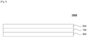
- an electrochemical device 1000 wherein the electrochemical device 1000 includes a cathode 300; an anode 500; a separation 100; and an electrolyte, wherein the separation 100 is interposed between the cathode 300 and the anode 500, and the separator 100 is the separator for an electrochemical device 100 according to the present invention.
- the electrochemical device can realize the viscosity of the electrolyte by adjusting the solubility of the polymer binder included in an adhesive layer for the electrolyte, can realize the surface resistance of the battery at a low level while simultaneously improving the ionic conductivity of the battery.
- Fig. 5 is a schematic diagram of an electrochemical device 1000 according to an exemplary embodiment of the present disclosure. Referring to FIG. 5 , the electrochemical device 1000 according to an exemplary embodiment of the present disclosure will be described in detail.
- the electrochemical device is a device that converts chemical energy into electrical energy by an electrochemical energy, and it is a concept that encompasses both primary and secondary batteries.
- the secondary battery is capable of charging and discharging, and refers to a lithium secondary battery, a nickel-cadmium battery, a nickel-hydrogen battery, etc.
- the lithium secondary battery uses lithium ions as an ion conductor, and examples of the lithium secondary battery may include a non-aqueous electrolyte secondary battery including liquid electrolyte, an all-solid battery including solid electrolyte, a lithium polymer battery including gel polymer electrolyte, a lithium metal battery using a lithium metal as an anode, etc., but is not limited thereto.
- the cathode is provided with a cathode current collector and a cathode active material layer, which includes a cathode active material, a conductive material, and a binder resin on at least one surface of the current collector.
- the cathode active material may include one or a mixture of two or more among a layered compound (e.g., lithium manganese composite oxide (LiMn 2 O 4 , LiMnO 2 , etc .), lithium cobalt oxide (LiCoO 2 ), lithium nickel oxide (LiNiO 2 ), etc .) or a compound substituted with one or more transition metals; lithium manganese oxide (e.g., Chemical Formula Li 1+x Mn 2-x O 4 (wherein x is 0 to 0.33), LiMnO 3 , LiMn 2 O 3 , LiMnO 2 , etc .); lithium copper oxide (e.g., LizCuOz); vanadium oxide (e .g., LiVsOs, LiV 3 O 4 , V 2 O 5 , Cu 2 V 2 O 7 , etc .); Ni site-type lithium nickel oxide represented by Chemical Formula LiNi 1-x M x O 2 (wherein M is Co, Mn, Al, Cu, Cu
- the anode is provided with an anode collector and an anode active material layer, which includes an anode active material, a conductive material, and a polymer binder on at least one surface of the collector.
- the anode may include, as an anode active material, one or a mixture of two or more from among carbon such as non-graphitizing carbon and graphite-based carbon ( e.g., non-graphitizing carbon, graphite-based carbon, etc .) ; metal composite oxides (e.g., LixFe 2 O 3 (0 ⁇ x ⁇ 1), Li x WO 2 (0 ⁇ x ⁇ 1), SnxMe1-xMe' y O z (Me: Mn, Fe, Pb, Ge; Me': Al, B, P, Si, elements in Groups I, II, and III of the periodic table, halogens; 0 ⁇ x ⁇ 1; 1 ⁇ y ⁇ 3; 1 ⁇ z ⁇ 8), etc .); lithium metals; lithium
- the conductive material may be, for example, any one or a mixture of two or more kinds of conductive materials selected from the group consisting of graphite, carbon black, carbon fibers or metal fibers, metal powders, conductive whiskers, conductive metal oxides, activated carbon, and polyphenylene derivatives.
- the graphite sheet has a cylindrical shape with a nano-sized diameter and an sp 2 bonding structure, and exhibits the characteristics of a conductor or semiconductor depending on the angle and structure at which the graphite plane is rolled.
- carbon nanotubes may be a mixture of one or two or more kinds of conductive materials selected from the group consisting of natural graphite, artificial graphite, super-p, acetylene black, ketjen black, channel black, furnace black, lamp black, summer black, denka black, aluminum powder, nickel powder, zinc oxide, potassium titanate, and titanium oxide.
- the current collector is not particularly limited as long as it has high conductivity without causing chemical changes in the electrochemical device, and for example, stainless steel, copper, aluminum, nickel, titanium, calcined carbon, or aluminum, or stainless steel whose surface is treated with carbon, nickel, titanium, silver, etc. may be used.
- polymers commonly used in electrodes in the art may be used as the polymer binder resin.
- binder resin may include polyvinylidene fluoride-co-hexafluoropropylene, polyvinylidene fluoride-cotrichloroethylene, polymethylmethacrylate, polyethylhexyl acrylate, polybutylacrylate, polyacrylonitrile, polyvinylpyrrolidone, polyvinylacetate, polyethylene-co-vinyl acetate, polyethylene oxide, polyarylate, cellulose acetate, cellulose acetate butyrate, cellulose acetatepropionate, cyanoethylpullulan, cyanoethylpolyvinylalcohol, cyanoethylcellulose, cyanoethylsucrose, pullulan, carboxyl methyl cellulose, etc., but are not limited thereto.
- a cathode slurry for preparing the cathode active material layer may include a dispersant, and the dispersing agent may be a pyrrolidone-based compound. Specifically, it may be N-methylpyrrolidone (ADC-01, LG Chem).
- the content of the dispersant included in the cathode slurry may be greater than 0 parts by weight and equal to or less than 0.5 parts by weight based on 100 parts by weight of the cathode slurry. Specifically, the content of the dispersant included in the cathode slurry may be greater than 005 parts by weight and equal to or less than 0.4 parts by weight based on 100 parts by weight of the cathode slurry.
- an anode slurry for preparing the anode active material layer may include a dispersant, and the dispersant may be a polypyrrolidone-based compound.
- the dispersant may be polyvinylpyrrolidone (Junsei Co., Ltd., Japan).
- the content of the dispersant included in the anode slurry may be greater than 0 parts by weight and equal to or less than 0.5 parts by weight based on 100 parts by weight of the anode slurry. Specifically, the content of the dispersant included in the anode slurry may be greater than 0.05 parts by weight and equal to or less than 0.4 parts by weight based on 100 parts by weight of the anode slurry.
- the electrochemical device prepared as described above can be charged into an appropriate case and a battery can be manufactured by injecting an electrolyte.
- the electrolyte is a salt having a structure of A+B-, in which A+ includes an alkali metal cation (e.g., Li+, Na+, and K+) or an ion composed of a combination thereof, B- is an anion (e.g., PF6-, BF4-, Cl-, Br-, I-, ClO 4 -, AsF 6 -, CH 3 CO 2 -, which is dissolved or dissociated in propylene carbonate (PC), ethylene carbonate (EC), diethyl carbonate (DEC), dimethyl carbonate (DMC), dipropyl carbonate (DPC), dimethyl sulfoxide, acetonitrile, dimethoxyethane, diethoxyethane, tetrahydrofuran, N-methyl-2-pyrrolidone (NMP), ethyl methyl carbonate (EMC), gamma ( ⁇ ) butyrolactone or an organic solvent
- A+ includes an alkali metal
- the solubility of the second polymer binder for the electrolyte at room temperature may be 50 (w/w)% or more and 80 (w/w)% or less.
- the solubility of the second polymer binder for the electrolyte at room temperature may be 51 (w/w)% or more, 52 (w/w)% or more, 53 (w/w)% or more, 54 (w/w)% or more, 55 (w/w)% or more, 56 (w/w)% or more, 57 (w/w)% or more, 58 (w/w)% or more, 59 (w/w)% or more, 60 (w/w)% or more, 61 (w/w)% or more, 62 (w/w)% or more, 63 (w/w)% or more, or 64 (w/w)% or more.
- the solubility of the second polymer binder for the electrolyte at room temperature may be 79 (w/w)% or less, 78 (w/w)% or less, 77 (w/w)% or less, 76 (w/w)% or less, 75 (w/w)% or less, 74 (w/w)% or less, 73 (w/w)% or less, 72 (w/w)% or less, 71 (w/w)% or less, 70 (w/w)% or less, 69 (w/w)% or less, 68 (w/w)% or less, 67 (w/w)% or less, or 66 (w/w)% or less.
- the solubility of the second polymer binder for the electrolyte at room temperature may be 51 (w/w)% or more and 79 (w/w)% or less, 52 (w/w)% or more and 78 (w/w)% or less, 53 (w/w)% or more and 77 (w/w)% or less, 54 (w/w)% or more and 76 (w/w)% or less, 55 (w/w)% or more and 75 (w/w)% or less, 56 (w/w)% or more and 74 (w/w)% or less, 57 (w/w)% or more and 73 (w/w)% or less, 58 (w/w)% or more and 72 (w/w)% or less, 59 (w/w)% or more and 71 (w/w)% or less, 60 (w/w)% or more and 70 (w/w)% or less, 61 (w/w)% or more and 69 (w/w)% or
- the solubility of the third polymer binder for the electrolyte at room temperature may be 50 (w/w)% or more and 80 (w/w)% or less.
- the solubility of the third polymer binder for the electrolyte at room temperature may be 51 (w/w)% or more, 52 (w/w)% or more, 53 (w/w)% or more, 54 (w/w)% or more, 55 (w/w)% or more, 56 (w/w)% or more, 57 (w/w)% or more, 58 (w/w)% or more, 59 (w/w)% or more, 60 (w/w)% or more, 61 (w/w)% or more, 62 (w/w)% or more, 63 (w/w)% or more, 64 (w/w)% or more.
- the solubility of the third polymer binder for the electrolyte at room temperature may be 79 (w/w)% or less, 78 (w/w)% or less, 77 (w/w)% or less, 76 (w/w)% or less, 75 (w/w)% or less, 74 (w/w)% or less, 73 (w/w)% or less, 72 (w/w)% or less, 71 (w/w)% or less, 70 (w/w)% or less, 69 (w/w)% or less, 68 (w/w)% or less, 67 (w/w)% or less, or 66 (w/w)% or less.
- the solubility of the third polymer binder for the electrolyte at room temperature may be 51 (w/w)% or more and 79 (w/w)% or less, 52 (w/w)% or more and 78 (w/w)% or less, 53 (w/w)% or more and 77 (w/w)% or less, 54 (w/w)% or more and 76 (w/w)% or less, 55 (w/w)% or more and 75 (w/w)% or less, 56 (w/w)% or more and 74 (w/w)% or less, 57 (w/w)% or more and 73 (w/w)% or less, 58 (w/w)% or more and 72 (w/w)% or less, 59 (w/w)% or more and 71 (w/w)% or less, 60 (w/w)% or more and 70 (w/w)% or less, 61 (w/w)% or more and 69 (w/w)% or
- a device which includes a battery including the electrode assembly as a unit cell, a battery pack including the battery module, and a device including the battery pack as a power source.
- the device may include a power tool powered by an electric motor; electric vehicles (EVs) including electric vehicles (EVs), hybrid electric vehicles (HEVs), plug-in hybrid electric vehicles (PHEVs), etc .; electric two-wheeled vehicles including electric bicycles (E-bikes) and electric scooters (E-scooters); electric golf carts; power storage systems, etc., but is not limited thereto.
- Polyethylene resin (weight average molecular weight: 900,000) was extruded, and a porous polymer substrate (total thickness: about 9 ⁇ m, porosity: 40 vol%) was prepared by a wet method.
- Al 2 O 3 powder having a D 50 particle size of 600 nm was prepared.
- An acrylic emulsion (CSB-130, Toyo Ink Co.) was prepared as the first binder polymer, and sodium carboxymethyl cellulose (CMC-Na) (SG-L02, GL Chem Co.) was prepared as a dispersant.
- CMC-Na sodium carboxymethyl cellulose
- Both surfaces of the porous polymer substrate were coated with the slurry for a coating layer and dried to form a coating layer, respectively.
- polyvinyl acetate in the form of particles with an average diameter (D 50 ) of 500 nm was added to water as a solvent and dispersed so that the solid content became 20 wt% to prepare a slurry for an adhesive layer.
- a separator for an electrochemical device was manufactured by applying the slurry for an adhesive layer to the coating layer by bar coating such that the loading amount of polyvinyl acetate became 1.0 g/m 2 , and then dried to form an adhesive layer.
- a separator for an electrochemical device was manufactured in the same manner as in Example 1 above except that the slurry for an adhesive layer was coated by bar coating such that the loading amount of polyvinyl acetate became 0.5 g/m 2 , and then dried to form an adhesive layer in Example 1 above.
- a separator for an electrochemical device was manufactured in the same manner as in Example 1 above except that the slurry for an adhesive layer was coated by spray coating such that the loading amount of polyvinyl acetate became 0.2 g/m 2 , and then dried to form an adhesive layer in Example 1 above.
- a separator for an electrochemical device was manufactured in the same manner as in Example 1 above except that polyvinyl acetate (PVAc) (i.e., a second polymer binder) and a copolymer of polyvinylidene fluoride (PVdF) and hexafluoropropylene (HFP) (BG4430 of Arkema company) (i.e., a third polymer binder) were mixed in a weight ratio of 70:30 and added to water ( i.e., a solvent) to prepare a slurry for the adhesive layer, and the slurry for the adhesive layer was coated by bar coating such that the loading amount of the sum of the polyvinyl acetate (PVAc) and the copolymer of polyvinylidene fluoride and hexafluoropropylene (PVdF-HFP) became 0.5 g/m 2 , and then dried to form an adhesive layer in Example 1 above.
- PVAc polyvinyl a
- a separator for an electrochemical device was manufactured in the same manner as in Example 1 above except that the adhesive layer is formed such that the second polymer binder is provided to 50 % of area based the total area of the coating layer in Example 1 above.
- Polyethylene resin (weight average molecular weight of 900,000) was extruded, and a porous polymer substrate (total thickness of about 9 ⁇ m) was prepared by a wet method.
- a copolymer of polyvinylidene fluoride and hexafluoropropylene (PVdF-HFP) (Solef21510, Solvay Co.) was prepared as the binder polymer, and sodium carboxymethyl cellulose (CMC-Na) (SG-L02, GL Chem Co.) was prepared as a dispersant.
- PVdF-HFP polyvinylidene fluoride and hexafluoropropylene
- CMC-Na sodium carboxymethyl cellulose
- a slurry for a coating layer was prepared by dissolving the polymer binder.
- a separator for an electrochemical device was manufactured by applying the slurry for a coating layer to both sides of the porous polymer substrate such that the loading amount became 3.2 g/m 2 , and then forming a coating layer using a humidified phase separation method.
- a separator for an electrochemical device was manufactured in the same manner as in Example 1 above except that acrylate (ADS11, LGC Co.) (i.e., an acrylic resin) was used as a second polymer binder in Example 1 above.
- acrylate ADS11, LGC Co.
- acrylic resin i.e., an acrylic resin
- a separator for an electrochemical device was manufactured in the same manner as in Example 1 above except that only a copolymer of polyvinylidene fluoride and hexafluoropropylene (PVdF-HFP) (LBG4430LX, Arkema Co.) was used as a second polymer binder in Example 1 above.
- PVdF-HFP polyvinylidene fluoride and hexafluoropropylene
- a separator for an electrochemical device was manufactured in the same manner as in Example 1 above except that as a second polymer binder, a mixture in which acrylate (ADS11, LGC Co.) (i.e., an acrylic resin) and a copolymer of polyvinylidene fluoride and hexafluoropropylene (PVdF-HFP) (LBG4430LX, Arkema Co.) were mixed in a weight ratio of 5:5 was used in Example 1 above.
- acrylate i.e., an acrylic resin
- PVdF-HFP polyvinylidene fluoride and hexafluoropropylene
- a separator for an electrochemical device was manufactured in the same manner as in Example 1 above except that a polyolefin wax (Chemipal W700, Mitsui Chemicals, Co., Ltd.) was used as a second polymer binder in Example 1 above.
- a polyolefin wax (Chemipal W700, Mitsui Chemicals, Co., Ltd.) was used as a second polymer binder in Example 1 above.
- a separator for an electrochemical device was manufactured in the same manner as in Example 1 above except that the slurry for an adhesive layer was coated by bar coating such that the loading amount of polyvinyl acetate became 1.5 g/m 2 , and then dried to form an adhesive layer in Example 1 above.
- a cathode active material LiNi 0.8 Mn 0.1 Co 0.1 O 2
- a conductive material carbon black
- a dispersant N -methylpyrrolidone, ADC-01, LG Chem
- a binder resin PVDF-HFP and PVDF mixed
- Graphite (a blend of natural graphite and artificial graphite), a conductive material (carbon black), a dispersant (polyvinylpyrrolidone, Junsei Co., Japan), and a binder resin (a mixture of PVDF-HFP and PVDF) were mixed with water in a weight ratio of 97.5:0.7:0.14:1.66, and thereby a slurry for an anode active material layer having a concentration of 50 wt% of the remaining components except water was prepared. Then, the slurry was applied to the surface of a copper thin film (10 ⁇ m in thickness) and dried to prepare an anode having an anode active material layer (120 ⁇ m in thickness).
- An electrode assembly was obtained by laminating the prepared anode and cathode with the separators of Example and Comparative Examples interposed therebetween and performing a lamination process.
- the lamination process was performed using a hot press under 70°C and 5.2 MPa conditions for 10 seconds.
- Specimens were prepared by cutting each of the separators of Examples 1 to 5 and Comparative Examples 1 to 5 into a size of 70 mm (length) ⁇ 25 mm (width), and laminating the prepared anode and the separator using a press under 60°C and 6.5 MPa conditions for 1 sec.
- the prepared specimend were fixed by attaching to a glass plate using double-sided tape, and in particular, an anode was placed to face the glass plate.
- the separator portion of each specimen was peeled at an angle of 180° at a speed of 150 mm/min at 25°C, and the strength at this time was measured and the results are summarized in Table 1 below.
- Specimens were prepared by cutting each of the separators of Examples 1 to 5 and Comparative Examples 1 to 5 into a size of 70 mm (length) ⁇ 25 mm (width), and laminating the prepared anode and the separator using a press under 60°C and 6.5 MPa conditions for 1 sec.
- the prepared specimens were each loaded into a battery case with electrolyte and maintained therein for 4 hours to impregnate the specimen with electrolyte.
- electrolyte a mixture of ethylene carbonate and ethylmethyl carbonate in a volume ratio of 7:3 and LiPF 6 prepared at a concentration of 1 M was used.
- each separator was interposed between SUS, and electrolyte was injected to make a coin cell, and the resistance (ER) was measured by the EIS method and the results are summarized in Table 1 below.
- the frequency was set to be in the range of 10,000 Hz to 100,000 Hz.
- the electrolyte is a mixture in which LiPF 6 was mixed to a concentration of 1 M in a non-aqueous solvent in which ethylene carbonate and ethyl methyl carbonate were mixed in a 3:7 ratio.
- the electrochemical devices using the separators of Examples 1 to 5 and Comparative Examples 1 to 5 were charged/discharged once at 0.1 C in a voltage range of 3.0 V to 4.4 V in a 25 ° C chamber using an electrochemical charger and discharger, their life characteristics were measured 200 times while proceeding with charging at 1.0 C and discharging at 1.0 C.
- the ratio of the discharge capacity after 200 cycles to the discharge capacity after one cycle was expressed as a capacity retention rate by the calculation using Equation 2 below, and the results of the life characteristics are summarized in Table 1 below.
- the separator of Comparative Example 1 which is a separator using a humidified phase separation method without a separate adhesive layer
- the heat shrinkage rate was high
- the separator of Comparative Example 2 which includes only acrylic resin in the adhesive layer
- the separator of Comparative Example 3 which includes only a copolymer of polyvinylidene fluoride and hexafluoropropylene
- the separator of Comparative Example 4 which includes acrylic resin and a copolymer of polyvinylidene fluoride and hexafluoropropylene together
- the resistance of the separator was increased while the capacity retention rates at room temperature cycle was decreased.
- the separator for an electrochemical device is characterized in that it includes a polyvinyl acetate-based resin in the adhesive layer, and can improve battery performance by reducing membrane resistance and increase the capacity retention rate at room temperature cycle by adjusting the content of the polyvinyl acetate-based resin.
Landscapes
- Chemical & Material Sciences (AREA)
- Chemical Kinetics & Catalysis (AREA)
- Electrochemistry (AREA)
- General Chemical & Material Sciences (AREA)
- Inorganic Chemistry (AREA)
- Engineering & Computer Science (AREA)
- Composite Materials (AREA)
- Materials Engineering (AREA)
- Cell Separators (AREA)
Applications Claiming Priority (2)
| Application Number | Priority Date | Filing Date | Title |
|---|---|---|---|
| KR20230026495 | 2023-02-28 | ||
| KR1020240007842A KR20240133563A (ko) | 2023-02-28 | 2024-01-18 | 전기화학소자용 분리막 및 이를 포함하는 전기화학소자 |
Publications (2)
| Publication Number | Publication Date |
|---|---|
| EP4425680A2 true EP4425680A2 (de) | 2024-09-04 |
| EP4425680A3 EP4425680A3 (de) | 2024-09-18 |
Family
ID=89663640
Family Applications (1)
| Application Number | Title | Priority Date | Filing Date |
|---|---|---|---|
| EP24153077.3A Pending EP4425680A3 (de) | 2023-02-28 | 2024-01-22 | Belüfter für eine elektrochemische vorrichtung und elektrochemische vorrichtung damit |
Country Status (5)
| Country | Link |
|---|---|
| US (1) | US20260031478A1 (de) |
| EP (1) | EP4425680A3 (de) |
| JP (1) | JP2025524092A (de) |
| CN (1) | CN119585936A (de) |
| WO (1) | WO2024181689A1 (de) |
Families Citing this family (1)
| Publication number | Priority date | Publication date | Assignee | Title |
|---|---|---|---|---|
| CN118522845A (zh) * | 2024-03-28 | 2024-08-20 | 比亚迪股份有限公司 | 锂离子电池和用电设备 |
Citations (2)
| Publication number | Priority date | Publication date | Assignee | Title |
|---|---|---|---|---|
| KR20230026495A (ko) | 2020-06-29 | 2023-02-24 | 신테크 코퍼레이션 | 고순도 비스-(2-하이드록시에틸)테레프탈레이트의 제조 방법, 재생 폴리에틸렌테레프탈레이트, 탈색 용매 및 비스-(2-하이드록시에틸)테레프탈레이트의 정제 방법 |
| KR20240007842A (ko) | 2022-07-08 | 2024-01-17 | 주식회사 서흥 | 유산균을 함유한 다중캡슐 |
Family Cites Families (10)
| Publication number | Priority date | Publication date | Assignee | Title |
|---|---|---|---|---|
| WO1999031750A1 (fr) * | 1997-12-18 | 1999-06-24 | Mitsubishi Denki Kabushiki Kaisha | Adhesif pour elements, element l'utilisant et procede de fabrication d'elements |
| KR20150106808A (ko) * | 2013-11-21 | 2015-09-22 | 삼성에스디아이 주식회사 | 이차 전지 및 이의 제조 방법 |
| KR101915339B1 (ko) * | 2014-11-07 | 2018-11-05 | 주식회사 엘지화학 | 분리막, 분리막-전극 복합체 및 이를 포함하는 전기화학소자 |
| KR101938385B1 (ko) * | 2014-12-08 | 2019-04-11 | 주식회사 엘지화학 | 바인더 고분자 층을 갖는 전기화학소자용 세퍼레이터 및 이를 포함하는 전기화학소자 |
| US10991926B2 (en) * | 2015-11-11 | 2021-04-27 | Lg Chem, Ltd. | Separator having electrode adhesive layer and electrochemical device including the same |
| KR102434168B1 (ko) * | 2016-09-21 | 2022-08-19 | 데이진 가부시키가이샤 | 비수계 이차 전지용 세퍼레이터 및 비수계 이차 전지 |
| KR102697158B1 (ko) * | 2018-01-08 | 2024-08-22 | 주식회사 엘지에너지솔루션 | 수계 접착층을 구비한 이차전지용 분리막 |
| EP4203168A4 (de) * | 2020-08-28 | 2025-06-04 | LG Energy Solution, Ltd. | Separator für elektrochemische vorrichtung und elektrochemische vorrichtung damit |
| KR102865418B1 (ko) * | 2020-10-16 | 2025-09-26 | 주식회사 엘지에너지솔루션 | 리튬 이차 전지용 분리막 및 이의 제조방법 |
| US20230261326A1 (en) * | 2020-10-19 | 2023-08-17 | Lg Energy Solution, Ltd. | Separator and lithium secondary battery comprising same |
-
2024
- 2024-01-19 JP JP2025504224A patent/JP2025524092A/ja active Pending
- 2024-01-19 WO PCT/KR2024/000942 patent/WO2024181689A1/ko not_active Ceased
- 2024-01-19 CN CN202480003426.4A patent/CN119585936A/zh active Pending
- 2024-01-19 US US18/996,826 patent/US20260031478A1/en active Pending
- 2024-01-22 EP EP24153077.3A patent/EP4425680A3/de active Pending
Patent Citations (2)
| Publication number | Priority date | Publication date | Assignee | Title |
|---|---|---|---|---|
| KR20230026495A (ko) | 2020-06-29 | 2023-02-24 | 신테크 코퍼레이션 | 고순도 비스-(2-하이드록시에틸)테레프탈레이트의 제조 방법, 재생 폴리에틸렌테레프탈레이트, 탈색 용매 및 비스-(2-하이드록시에틸)테레프탈레이트의 정제 방법 |
| KR20240007842A (ko) | 2022-07-08 | 2024-01-17 | 주식회사 서흥 | 유산균을 함유한 다중캡슐 |
Also Published As
| Publication number | Publication date |
|---|---|
| US20260031478A1 (en) | 2026-01-29 |
| JP2025524092A (ja) | 2025-07-25 |
| EP4425680A3 (de) | 2024-09-18 |
| CN119585936A (zh) | 2025-03-07 |
| WO2024181689A1 (ko) | 2024-09-06 |
Similar Documents
| Publication | Publication Date | Title |
|---|---|---|
| EP4358270A1 (de) | Verfahren zur herstellung eines lithiumsekundärbatterieseparators, damit hergestellter lithiumsekundärbatterieseparator und lithiumsekundärbatterie damit | |
| US20250183482A1 (en) | Separator for secondary battery, preparation method therefor, and secondary battery comprising same | |
| EP4425680A2 (de) | Belüfter für eine elektrochemische vorrichtung und elektrochemische vorrichtung damit | |
| EP4607682A1 (de) | Selbsttragender separator für elektrochemische vorrichtung und elektrochemische vorrichtung damit | |
| EP4661191A2 (de) | Separator für elektrochemische vorrichtung und elektrochemische vorrichtung damit | |
| EP4425678A1 (de) | Separator für elektrochemische vorrichtung und elektrochemische vorrichtung damit | |
| EP4425681A2 (de) | Belüfter für eine elektrochemische vorrichtung, elektrochemische vorrichtung damit und herstellungsverfahren dafür | |
| KR102919882B1 (ko) | 전기화학소자용 분리막 및 이를 포함하는 전기화학소자 | |
| US20240396162A1 (en) | Separator for electrochemical device including polymer binder layer, electrochemical device including the same and manufacturing method thereof | |
| KR102900371B1 (ko) | 전기화학소자용 분리막, 이를 포함하는 전기화학소자 및 이의 제조하는 방법 | |
| KR102563504B1 (ko) | 전기화학소자용 폴리올레핀 분리막 및 이를 구비한 전기화학소자 | |
| EP4528906A1 (de) | Separator für elektrochemische vorrichtung und elektrochemische vorrichtung damit | |
| US20260088447A1 (en) | Composition for forming coating layer and method for manufacturing separator for electrochemical device using the same | |
| EP4560817A1 (de) | Separator für elektrochemische vorrichtung und elektrochemische vorrichtung damit | |
| EP4614711A1 (de) | Separator für elektrochemische vorrichtung und elektrochemische vorrichtung damit | |
| US20250392001A1 (en) | Electrochemical device separator, manufacturing method thereof, and electrochemical device including the same | |
| EP4369503A1 (de) | Verfahren zur herstellung eines separators für eine lithiumsekundärbatterie, damit hergestellter separator für eine lithiumsekundärbatterie und verfahren zur herstellung einer lithiumsekundärbatterie damit | |
| KR20240133563A (ko) | 전기화학소자용 분리막 및 이를 포함하는 전기화학소자 | |
| KR20250179084A (ko) | 전기화학소자용 분리막, 이의 제조방법 및 이를 포함하는 전기화학소자 | |
| KR20250179089A (ko) | 전기화학소자용 분리막 및 이를 포함하는 전기화학소자 | |
| EP4715995A1 (de) | Separator für elektrochemische vorrichtung und elektrochemische vorrichtung damit | |
| EP4246699A1 (de) | Verfahren zur herstellung einer elektrodenanordnung für eine elektrochemische vorrichtung, durch dieses verfahren erhaltene elektrodenanordnung und verfahren zur herstellung einer elektrochemischen vorrichtung | |
| KR20230171646A (ko) | 고용량의 전극을 구비하는 리튬 이차전지 | |
| KR20240161030A (ko) | 전기화학소자용 자립형 분리막 및 이를 포함하는 전기화학소자 | |
| KR20260034585A (ko) | 전기화학소자용 분리막 및 이를 포함하는 전기화학소자 |
Legal Events
| Date | Code | Title | Description |
|---|---|---|---|
| PUAI | Public reference made under article 153(3) epc to a published international application that has entered the european phase |
Free format text: ORIGINAL CODE: 0009012 |
|
| STAA | Information on the status of an ep patent application or granted ep patent |
Free format text: STATUS: REQUEST FOR EXAMINATION WAS MADE |
|
| PUAL | Search report despatched |
Free format text: ORIGINAL CODE: 0009013 |
|
| 17P | Request for examination filed |
Effective date: 20240122 |
|
| AK | Designated contracting states |
Kind code of ref document: A2 Designated state(s): AL AT BE BG CH CY CZ DE DK EE ES FI FR GB GR HR HU IE IS IT LI LT LU LV MC ME MK MT NL NO PL PT RO RS SE SI SK SM TR |
|
| AK | Designated contracting states |
Kind code of ref document: A3 Designated state(s): AL AT BE BG CH CY CZ DE DK EE ES FI FR GB GR HR HU IE IS IT LI LT LU LV MC ME MK MT NL NO PL PT RO RS SE SI SK SM TR |
|
| RIC1 | Information provided on ipc code assigned before grant |
Ipc: H01M 10/052 20100101ALN20240812BHEP Ipc: H01M 50/489 20210101ALI20240812BHEP Ipc: H01M 50/46 20210101ALI20240812BHEP Ipc: H01M 50/451 20210101ALI20240812BHEP Ipc: H01M 50/443 20210101ALI20240812BHEP Ipc: H01M 50/426 20210101ALI20240812BHEP Ipc: H01M 50/414 20210101ALI20240812BHEP Ipc: H01M 50/446 20210101AFI20240812BHEP |
|
| STAA | Information on the status of an ep patent application or granted ep patent |
Free format text: STATUS: EXAMINATION IS IN PROGRESS |
|
| 17Q | First examination report despatched |
Effective date: 20251023 |