EP4403333A1 - Einleger und verfahren zum anfahren eines spritzgussprozesses - Google Patents
Einleger und verfahren zum anfahren eines spritzgussprozesses Download PDFInfo
- Publication number
- EP4403333A1 EP4403333A1 EP23200130.5A EP23200130A EP4403333A1 EP 4403333 A1 EP4403333 A1 EP 4403333A1 EP 23200130 A EP23200130 A EP 23200130A EP 4403333 A1 EP4403333 A1 EP 4403333A1
- Authority
- EP
- European Patent Office
- Prior art keywords
- insert
- injection molding
- region
- molding tool
- cable
- Prior art date
- Legal status (The legal status is an assumption and is not a legal conclusion. Google has not performed a legal analysis and makes no representation as to the accuracy of the status listed.)
- Granted
Links
Images




Classifications
-
- B—PERFORMING OPERATIONS; TRANSPORTING
- B29—WORKING OF PLASTICS; WORKING OF SUBSTANCES IN A PLASTIC STATE IN GENERAL
- B29C—SHAPING OR JOINING OF PLASTICS; SHAPING OF MATERIAL IN A PLASTIC STATE, NOT OTHERWISE PROVIDED FOR; AFTER-TREATMENT OF THE SHAPED PRODUCTS, e.g. REPAIRING
- B29C45/00—Injection moulding, i.e. forcing the required volume of moulding material through a nozzle into a closed mould; Apparatus therefor
- B29C45/17—Component parts, details or accessories; Auxiliary operations
- B29C45/76—Measuring, controlling or regulating
- B29C45/766—Measuring, controlling or regulating the setting or resetting of moulding conditions, e.g. before starting a cycle
-
- B—PERFORMING OPERATIONS; TRANSPORTING
- B29—WORKING OF PLASTICS; WORKING OF SUBSTANCES IN A PLASTIC STATE IN GENERAL
- B29C—SHAPING OR JOINING OF PLASTICS; SHAPING OF MATERIAL IN A PLASTIC STATE, NOT OTHERWISE PROVIDED FOR; AFTER-TREATMENT OF THE SHAPED PRODUCTS, e.g. REPAIRING
- B29C45/00—Injection moulding, i.e. forcing the required volume of moulding material through a nozzle into a closed mould; Apparatus therefor
- B29C45/14—Injection moulding, i.e. forcing the required volume of moulding material through a nozzle into a closed mould; Apparatus therefor incorporating preformed parts or layers, e.g. injection moulding around inserts or for coating articles
-
- B—PERFORMING OPERATIONS; TRANSPORTING
- B29—WORKING OF PLASTICS; WORKING OF SUBSTANCES IN A PLASTIC STATE IN GENERAL
- B29B—PREPARATION OR PRETREATMENT OF THE MATERIAL TO BE SHAPED; MAKING GRANULES OR PREFORMS; RECOVERY OF PLASTICS OR OTHER CONSTITUENTS OF WASTE MATERIAL CONTAINING PLASTICS
- B29B11/00—Making preforms
- B29B11/14—Making preforms characterised by structure or composition
-
- B—PERFORMING OPERATIONS; TRANSPORTING
- B29—WORKING OF PLASTICS; WORKING OF SUBSTANCES IN A PLASTIC STATE IN GENERAL
- B29C—SHAPING OR JOINING OF PLASTICS; SHAPING OF MATERIAL IN A PLASTIC STATE, NOT OTHERWISE PROVIDED FOR; AFTER-TREATMENT OF THE SHAPED PRODUCTS, e.g. REPAIRING
- B29C45/00—Injection moulding, i.e. forcing the required volume of moulding material through a nozzle into a closed mould; Apparatus therefor
- B29C45/14—Injection moulding, i.e. forcing the required volume of moulding material through a nozzle into a closed mould; Apparatus therefor incorporating preformed parts or layers, e.g. injection moulding around inserts or for coating articles
- B29C45/14639—Injection moulding, i.e. forcing the required volume of moulding material through a nozzle into a closed mould; Apparatus therefor incorporating preformed parts or layers, e.g. injection moulding around inserts or for coating articles for obtaining an insulating effect, e.g. for electrical components
-
- B—PERFORMING OPERATIONS; TRANSPORTING
- B29—WORKING OF PLASTICS; WORKING OF SUBSTANCES IN A PLASTIC STATE IN GENERAL
- B29L—INDEXING SCHEME ASSOCIATED WITH SUBCLASS B29C, RELATING TO PARTICULAR ARTICLES
- B29L2031/00—Other particular articles
- B29L2031/34—Electrical apparatus, e.g. sparking plugs or parts thereof
- B29L2031/36—Plugs, connectors, or parts thereof
Definitions
- the invention relates to an insert for an injection molding tool and a method for starting an injection molding process, in particular for use in cable assembly.
- an insert comprises a prefabricated cable, whereby the actual cable or line is shortened for practical reasons.
- the (cable) inserts are manufactured separately or additionally and bring a Additional work and therefore costs.
- a (cable) insert has the following components: a contact carrier, two contacts, a hard plug, a soft plug and a cable. Other components can also be added here; this depends largely on the connector. The same applies to the process steps described below.
- This (cable) insert is then assembled using the following process steps: strip the cable, align the strands, put on the soft plug, put on the hard plug, strip the strands, crimp the contacts, align the contacts, check the contacts, insert the contacts into the housing, carry out a snap-in test of the contacts in the housing, assemble the plugs in the housing and carry out a final test.
- each injection molding tool or each connector to be overmolded requires its own (cable) insert, which means that a large number of different (cable) inserts are necessary or available.
- additional components could be inserted, depending on the connector.
- the metal bushing is manufactured and also inserted into the injection molding tool before the overmold process so that the volume to be overmolded corresponds to the original connector. The metal bushing generates additional costs. In addition to the costs, there is also an environmental aspect.
- (Cable) inserts that have been overmolded for the start-up process are declared as waste and disposal costs arise because the (cable) inserts consist of different materials, i.e. they form a composite material made of different plastics, copper, TPU, EVA and/or metal, and reuse or resale of the (cable) inserts is not possible.
- the above-mentioned object is achieved by an insert for an injection molding tool, wherein the insert in the injection molding tool forms a predetermined volume that can be overmolded with injection molding material, and the insert is made entirely of plastic.
- This insert is designed in particular for injection molding tools in cable assembly.
- This insert has the advantage that it is cheaper and more environmentally friendly than ready-made cable inserts from the state of the art.
- the inserts can be further processed after overmolding or even resold. Additional insert components, such as a metal bushing, are not required. Furthermore, the capacity of the affected systems is relieved or eliminated.
- the insert can be produced unmanned at weekends, in a so-called ghost shift.
- the quality control of the (plastic) insert is significantly lower than that of (cable) inserts from the state of the art.
- the plastic of the insert is the same as the injection molding material.
- the result would be a monolithic plastic object that can be very easily reused or sold.
- the insert can simply be shredded and recycled for reuse.
- the plastic comprises recycled material.
- recycled material is used which is made from sprues which are a by-product of plug production. is generated. The sprue is collected, ground and can then be used as material for the (plastic) inserts.
- the insert comprises at least three regions: a first region which can be used in an injection molding tool as a clamping region for a cable, a second region which can be overmolded in the injection molding tool as a transition region between the first and a third region, and the third region which can be used in the injection molding tool as a clamping region for a plug.
- the first area is intended to represent and replace a cable diameter.
- the geometry, diameter, length and/or number of cables can be exchanged and changed using inserts in the injection molding tool.
- the first area is preferably clamped off or sealed during overmolding so that no injection molding material or melt can escape from the injection molding tool during overmolding.
- the third area represents a respective plug that is attached to a prefabricated cable.
- the geometry is significantly simplified and preferably only comprises a receptacle and a clamping area.
- the simplified geometry reduces costs for the injection molding tool.
- the third area is preferably implemented as an insert in the injection molding tool so that the geometry, size, length and/or number can be varied.
- a plug also has a clamping area so that no injection molding material or melt can escape during overmolding.
- the second region preferably comprises a flexible element, in particular a spiral.
- the flexible region enables the insert to have flexible properties or functions like a prefabricated cable itself. This allows the number of different inserts to be reduced because, for example, a plug can have different angles and/or the orientation can be different (right/left, top/bottom, etc.), an insert can imitate both a hose with different diameters and shapes and a cable with different diameters and shapes. This is easily changed by changing inserts.
- a cable is designed to transmit electrical and/or optical signals.
- a hose is essentially a sleeve for one or more several cables or strands.
- a hose is used in particular when the cable has to be split, ie the strands are separated from a cable and then protected by the hose, which is pushed over the strands.
- the present (plastic) insert can be used in the same way as the cable inserts from the state of the art.
- the third region can be arranged bent in relation to the first region by the flexible element in the second region at least in the dimension of a hemisphere.
- the dimension can in particular also comprise more than just one hemisphere.
- the second region can in particular be deformed in such a way that the first and third regions touch each other.
- the second region should give the (plastic) insert the same or at least similar flexible properties as a (cable) insert in the prior art.
- the second region is preferably implemented in the injection mold as an insert in which the geometry, diameter, length and/or number of flexible elements or spirals is variable.
- the flexible element or spiral at least partially replaces the volume of the contact carrier, the volume of the wires of the cable and/or the volume of any metal inserts and at the same time remains as flexible as a (cable) insert from the prior art.
- the mobility extends up to 360° in all directions, i.e. a spherical area.
- the variance of the flexible geometry i.e. the flexible element or spiral, makes it possible to cover all outlets or variants with only one (insert) geometry.
- the volume of the insert preferably corresponds to the volume of a prefabricated cable to be overmolded.
- the volume is an essential process parameter in overmolding. The more accurately an insert in the start-up process reproduces or imitates the volume of the final object to be overmolded, ie a prefabricated cable, the more accurately the process can be adjusted. Since the plastic of the present insert is easy to work with, the volume of the insert can also be adjusted very easily, inexpensively and precisely.
- a method for starting an injection molding process comprising the following steps: inserting a plastic insert into an injection molding tool, closing the injection molding tool and starting the start-up process, finding all parameters so that a volumetric and thermal equilibrium is achieved or the parameters settle within a predetermined tolerance.
- the described start-up process has the advantage that it can be carried out more cheaply and in a more environmentally friendly way than start-up processes in the state of the art in which cable inserts are used.
- No new machines or injection molding tools are required for the present start-up process.
- a simple injection molding tool is sufficient for the process.
- the injection molding tools for the process can be inexpensive and no customer approval is necessary.
- the process is easy to implement and can be transferred to many different injection molding projects or connector types. The process can also be quickly transferred worldwide.
- the present process is preferably implemented with a modular injection molding tool that uses inserts and can therefore be used for both cables and hoses, for example.
- the steps are repeated until process stability is achieved.
- the number of repetitions can be set individually for each process. With a repeated sequence of process steps, an optimal injection molding process can easily be achieved or set.
- the plastic inserts enable quick repetition because they can be used easily and inexpensively.
- no other components need to be inserted into the injection molding tool in addition to inserting the plastic insert.
- additional insert components such as a metal bushing in the state of the art, are not required. This makes it easier to insert components for a start-up process, as it is not necessary to insert a metal bushing, for example. This also reduces the likelihood of damage to the Injection molding tool, for example by incorrectly inserting the metal bushings into the injection molding tool.
- Fig.1 shows an embodiment of an insert 1 for an injection molding tool 40.
- the insert 1 is particularly suitable for carrying out a start-up process in an injection molding tool 40.
- the insert 1 in the injection molding tool 40 forms a predetermined volume that can be overmolded with injection molding material.
- the insert 1 is made entirely of plastic.
- the insert 1 is preferably made of the same plastic with which the insert 1 is overmolded.
- the plastic from which the insert 1 is made can comprise recycled material.
- Recycled material can be made from sprue that is created during plug production. To produce or use the recycled material, the sprue is crushed or ground when it has hardened so that it forms a recycled material (different particle size, usually in the range of 2-5 mm) or can be further processed into regranulate, which has a uniform granulate size. This regranulate/recycled material can also be used to overmold the insert 1, at least during the start-up process in the injection molding tool 40.
- An insert 1 that is made entirely of plastic can be recycled more easily than a composite material, such as a cable insert 150 in the prior art. If the insert 1 is also made of the same material with which it is overmolded, the end product 170 is a monolithic plastic. This monolithic plastic can be easily recycled, for example by shredding it and feeding it back into an injection molding process.
- the insert 1 shown preferably comprises three areas 10, 20, 30.
- the first area 10 is modeled on a line 12.
- the first area 10 can be used in an injection molding tool 40 as a clamping area for a line 12.
- the geometry of the line 12 in the start-up process corresponds to the geometry of a prefabricated line that is to be overmolded later.
- the insert 1 shown also has a second area 20.
- the second area 20 forms a transition area in the injection molding tool 40 between the first area 10 and a third area 30.
- the second area 20 is essentially the area that is overmolded, i.e. in this area a large part of the injection molding material used is overmolded on the insert 1.
- the insert 1 shown also has a third area 30.
- the third area 30 imitates a plug that is attached to a prefabricated line.
- the third area 30 can be used in the injection molding tool 40 as a clamping area for a plug 36.
- the plug side 38 is only indicated in the illustrated insert 1, ie it has no Plug-in face for connection with a suitable mating connector and serves for orientation or alignment of the insert 1.
- the second region 20 of the insert 1 shown comprises a flexible element 24.
- the flexible element 24 is shown as a spiral in the embodiment shown. In alternative embodiments, the flexible element 24 can have other shapes as long as the flexibility function is present.
- the flexible element 24 in the second region 20 makes it possible to arrange the third region 30 bent relative to the first region 10 at least in the region of a hemisphere S or more than one hemisphere S, more preferably in the region of a sphere.
- different cable outlets i.e. straight or angled, can be represented in relation to a connector type.
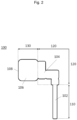
- the insert 100 has a connection part 104 in the second area 120, which is not flexible but has a rigid shape. Since the insert 150 is made of plastic, any shape for the connection part 104 can be easily produced and used.
- the insert 150 also has a line part 102 and a plug part 106 on two different sides of the connection part 104.
- the insert 150 can thus also be divided into a first 110, second 120 and third area 130. In use, each of the three areas 110, 120, 130 can be designed separately.
- the three areas 10, 20, 30, 110, 120, 130 of an insert 1, 100 can comprise different plastics. Regardless of which material is chosen or whether the second area 20, 120 comprises a flexible element 24 or not, the volume of the insert 1, 100 must correspond to the volume of a prefabricated cable to be overmolded, ie the cable that will later be overmolded in the (continuous or series) injection molding process that takes place after start-up.
- cable inserts 150 (see Fig.3 ) is used to carry out a start-up process.
- the cable inserts 150 correspond to short cables 152 that have been assembled with a connector 156.
- the wires 154 of the cable 152 were connected to the connector 156 via a connection 155.
- the plug side 158 on the connector 156 would in principle be suitable for being plugged into a suitable mating connector.
- a cable insert 150 is inserted into an injection molding tool 40, or into one half of an injection molding tool 40 (see Fig.4 ).
- the cable 152 is bent by 90 degrees to the plug 156, so that the wires 154 of the cable 152 are arranged in a bent manner.
- Recesses or inserts in the injection molding tool 40 form an external shape. Recesses that remain hollow or unfilled even after a cable insert 150 has been inserted form volumes for injection molding material 42.
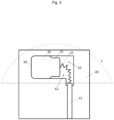
- the present method of starting an injection molding process is carried out with a (plastic) insert 1 (see Fig.5 ).
- the method is carried out in such a way that a plastic insert 1 is first inserted into an injection molding tool 40 or one half of an injection molding tool 40. Inserting the plastic insert 1 is particularly simple since preferably no further components have to be inserted into the injection molding tool 40.
- an insert geometry can be used for different injection molding geometries.
- the volume of the flexible element 24 and the connection part 25 is designed in such a way that it corresponds to the volume of the corresponding connection 155 and the wires 154.
- the injection molding tool 40 is closed and the start-up process is started.
- all essential parameters are determined or the already fixed parameters with the tolerances are already specified, and production continues until the process values are within the tolerances, so that a volumetric and thermal equilibrium is achieved or the parameters settle within a specified tolerance.
- the start-up can be repeated until process stability is achieved.
- Fig.6 showed an embodiment of an end product 170 that was created from an overmolding process, in particular a start-up process in an injection molding tool.
- the end product 170 is an overmolded insert 1, 100, 150 that has at least one line part 172, an overmolded connection part 174 and a plug-in side 178 that is visible.
- the external volume of the end product 170 of the (plastic) insert 1, 100 is the same as that of the (cable) insert 150.
Landscapes
- Engineering & Computer Science (AREA)
- Mechanical Engineering (AREA)
- Manufacturing & Machinery (AREA)
- Injection Moulding Of Plastics Or The Like (AREA)
- Moulds For Moulding Plastics Or The Like (AREA)
Abstract
Description
- Die Erfindung betrifft einen Einleger für ein Spritzgusswerkzeug und ein Verfahren zum Anfahren eines Spritzgussprozesses, insbesondere für die Verwendung in der Kabelkonfektion.
- In der Spritzgusstechnik, insbesondere wenn eine Komponente umspritzt werden muss, werden Einleger benötigt, um den Spritzgussprozess durch ein sogenanntes Anfahren zu starten. Dieser Anfahrprozess ist notwendig damit eine Prozessfindung aller Parameter in Bezug auf volumetrisches als auch thermisches Gleichgewicht durchgeführt bzw. erlangt werden kann, oder sich die Parameter in eine vorgegebene Toleranz einpendeln können. Der Anfahrprozess kann ohne Einleger nicht gestartet werden, da sonst das Spritzgusswerkzeug überspritzt wird und das Spritzgusswerkzeug zur Reinigung ausgebaut werden müsste. Oder, es werden Gut-Teile (ganze Leitungssätze) verwendet, welche jedoch anschließend entsorgt werden müssen, da die Qualität nicht stimmt bzw. sichergestellt werden kann. Somit würden höhere Kosten anfallen.
- Ein Einleger umfasst im Stand der Technik ein konfektioniertes Kabel, wobei das eigentliche Kabel bzw. die Leitung aus praktischen Gründen gekürzt ist. Die (Kabel-)Einleger werden gesondert bzw. zusätzlich hergestellt und bringen einen Mehraufwand und somit auch Kosten mit sich. In einem Ausführungsbeispiel im Stand der Technik weist ein (Kabel-)Einleger folgende Komponenten auf: einen Kontaktträger, zwei Kontakte, einen harten Stopfen, einen weichen Stopfen sowie eine Leitung. Hier können auch noch weiter Komponenten hinzukommen, dies ist stark vom Stecker abhängig. Dasselbe gilt auch dann für die im Folgenden beschriebenen Prozessschritte. Dieser (Kabel-)Einleger wird dann mit folgenden Prozessschritten zusammengebaut: Leitung abisolieren, Litzen ausrichten, den weichen Stopfen aufsetzen, den harten Stopfen aufsetzen, die Litzen abisolieren, die Kontakte crimpen, die Kontakte ausrichten, die Kontakte prüfen, die Kontakte ins Gehäuse fügen, eine Verrastprüfung der Kontakte im Gehäuse durchführen, eine Montage der Stopfen ins Gehäuse durchführen und eine finale Prüfung durchführen.
- Alle oben genannten Komponenten werden aus Gut-Ware entnommen und auch produziert. Es entstehen dadurch für die (Kabel-)Einleger beträchtliche Kosten. Weiterhin benötigt jedes Spritzgusswerkzeug bzw. jeder zu umspritzende Stecker seinen eigenen (Kabel-)Einleger, wodurch eine große Variantenanzahl an verschiedenen (Kabel-)Einlegern notwendig oder vorhanden ist. Darüber hinaus gibt es Stecker die eine weitere Komponente, eine sogenannte Metallbuchse, beim Umspritzten, und somit auch im Anfahrprozess, benötigen. Auch hier könnten weitere Komponenten eingelegt werden, abhängig vom Stecker. Die Metallbuchse wird gefertigt und vor dem Umspritzprozess ebenfalls ins Spritzgusswerkzeug eingelegt damit das zu umspritzende Volumen dem originalen Stecker entspricht. Die Metallbuchse erzeugt zusätzliche Kosten. Neben den Kosten gibt es auch einen Umweltaspekt. (Kabel-)Einleger, die für den Anfahrprozess umspritzt wurden, werden als Müll deklariert und Entsorgungskosten entstehen, da die (Kabel-)Einleger aus verschiedenen Werkstoffen bestehen, d.h. einen Verbundwerkstoff aus unterschiedlichen Kunststoffen, Kupfer, TPU, EVA und/oder Metall bilden, und eine Wiederverwendung bzw. ein Weiterverkauf der (Kabel-)Einleger nicht möglich ist.
- Es ist daher eine Aufgabe der vorliegenden Erfindung einen Einleger und einen Anfahrprozess für ein Spritzgusswerkzeug bereitzustellen, bei denen Kosten in Bezug auf die Einleger reduziert werden, gleichzeitig eine umweltschonende Produktion ermöglicht wird, Kapazitäten an Anlagen mit dem Einleger reduziert werden, damit diese für eine Serienfertigung genutzt werden können, und die Anzahl an verschiedenen Einlegern reduziert wird.
- Die oben genannte Aufgabe wird durch einen Einleger nach Anspruch 1 und ein Verfahren zum Anfahren eines Spritzgussprozesses nach Anspruch 8 gelöst. Weitere vorteilhafte Ausgestaltungsformen der Erfindung lassen sich den Unteransprüchen, der Beschreibung sowie den Zeichnungen entnehmen.
- Insbesondere wird die oben genannte Aufgabe gelöst durch einen Einleger für ein Spritzgusswerkzeug, wobei der Einleger im Spritzgusswerkzeug ein mit Spritzgussmaterial umspritzbares vorbestimmtes Volumen bildet, und der Einleger vollständig aus Kunststoff hergestellt ist.
- Der vorliegende Einleger ist insbesondere für Spritzgusswerkzeuge in der Kabelkonfektion bestimmt. Der vorliegende Einleger hat die Vorteile, dass er preiswerter und umweltschonender als konfektionierte Kabel-Einleger aus dem Stand der Technik ist. Vorliegende Einleger können nach der Umspritzung weiterverarbeitet oder auch weiterverkauft werden. Zusätzliche Einleger-Komponenten, wie eine Metall-Buchse, werden nicht benötigt. Weiterhin wird die Kapazität von betroffenen Anlagen entlastet bzw. entfällt. Der Einleger kann mannlos am Wochenende, in einer sogenannten Geisterschicht, erzeugt werden. Die Qualitätskontrolle ist beim (Kunststoff-)Einleger deutlich niedriger als bei (Kabel-)Einlegern im Stand der Technik.
- Bevorzugt entspricht der Kunststoff des Einlegers dem Spritzgussmaterial. In diesem Fall wäre das Ergebnis ein monolithischer Kunststoffgegenstand, der sehr einfach wiederverwendet oder verkauft werden kann. Für die Wiederverwendung kann der Einleger in diesem Fall einfach zerkleinert und recycelt werden.
- Bevorzugt umfasst der Kunststoff Recyclat. Insbesondere wird Recyclat verwendet, das aus Anguss hergestellt ist, der als Nebenprodukt bei der Steckerherstellung generiert wird. Der Anguss wird gesammelt, gemahlen und kann dann als Werkstoff für die (Kunststoff-)Einleger dienen.
- Bevorzugt umfasst der Einleger zumindest drei Bereiche: einen ersten Bereich, der in einem Spritzgusswerkzeug als Klemmbereich für eine Leitung verwendbar ist, einen zweiten Bereich, der in dem Spritzgusswerkzeug als Übergangsbereich zwischen dem ersten und einem dritten Bereich umspritzbar ist, und dem dritten Bereich, der in dem Spritzgusswerkzeug als Klemmbereich für einen Stecker verwendbar ist.
- Der erste Bereich soll einen Kabeldurchmesser darstellen und ersetzen. Durch Einsätze im Spritzgusswerkzeug kann die Geometrie, der Durchmesser, die Länge und/oder auch die Anzahl der Leitungen getauscht und geändert werden. Der erste Bereich wird bevorzugt beim Umspritzen abgeklemmt bzw. abgedichtet, so dass kein Spritzgussmaterial bzw. keine Schmelze während des Umspritzens aus dem Spritzgusswerkezug austreten kann. Der dritte Bereich stellt einen jeweiligen Stecker dar, der an einem konfektionierten Kabel befestigt ist. Allerdings wird die Geometrie deutlich vereinfacht, und umfasst bevorzugt lediglich eine Aufnahme und einen Klemmbereich. Die vereinfachte Geometrie reduziert Kosten an dem Spritzgusswerkzeug. Weiterhin wird der dritte Bereich bevorzugt als Einsatz in dem Spritzgusswerkzeug umgesetzt, damit die Geometrie, die Größe, die Länge und/oder auch die Anzahl variiert werden kann. Insbesondere weist ein Stecker auch einen Klemmbereich auf, damit auch hier kein Spritzgussmaterial bzw. keine Schmelze während des Umspritzens austreten kann.
- Bevorzugt umfasst der zweite Bereich ein flexibles Element, insbesondere eine Spirale. Der flexible Bereich ermöglicht dem Einleger flexible Eigenschaften oder Funktionen wie ein konfektioniertes Kabel selbst. So kann die Anzahl an verschiedenen Einlegern reduziert werden, weil zum Beispiel ein Stecker unterschiedliche Winkel aufweisen kann und/oder auch die Ausrichtung unterschiedlich sein kann (rechts/links, oben/unten usw.), ein Einleger sowohl einen Schlauch mit unterschiedlichen Durchmessern und Formen als auch ein Kabel mit unterschiedlichen Durchmessern und Formen imitieren kann. Dies wird einfach durch Wechseleinsätze geändert. Ein Kabel ist eingerichtet elektrische und/oder optische Signale zu übertragen. Ein Schlauch ist im Wesentlichen eine Hülle für ein oder mehrere Leitungen oder Litzen. Ein Schlauch wird insbesondere dann eingesetzt, wenn die Leitung gesplittet werden muss, d.h. aus einer Leitung werden die Litzen getrennt und dann durch den Schlauch geschützt, der über die Litzen geschoben wird. Durch das Nachstellen der flexiblen Eigenschaften einer Leitung oder eines Schlauchs kann der vorliegende (Kunststoff-)Einleger identisch wie die Kabel-Einleger aus dem Stand der Technik eingesetzt werden.
- Bevorzugt kann der dritte Bereich durch das flexible Element im zweiten Bereich zumindest in der Dimension einer Halbkugel gegenüber dem ersten Bereich verbogen angeordnet werden. Die Dimension kann insbesondere auch mehr als nur eine Halbkugel umfassen. Der zweite Bereich kann insbesondere so verformt werden, dass sich der erste und dritte Bereich berühren Der zweite Bereich soll dem (Kunststoff-)Einleger dieselben oder zumindest ähnliche flexible Eigenschaften verleihen, die bei einem (Kabel-)Einleger im Stand der Technik vorliegen. Der zweite Bereich wird bevorzugt im Spritzgusswerkzeug als Einsatz umgesetzt, bei dem die Geometrie, der Durchmesser, die Länge und/oder die Anzahl an flexiblen Elementen oder Spiralen variabel ist. Das flexible Element oder die Spirale ersetzt zumindest teilweise das Volumen des Kontaktträgers, das Volumen von Adern der Leitung und/oder das Volumen eventueller Metall-Einleger und bleibt gleichzeitig flexibel wie ein (Kabel-)Einleger aus dem Stand der Technik. Insbesondere geht die Beweglichkeit bis zu 360° in alle Richtungen, d.h. einem Kugelbereich. Insgesamt ermöglicht die Varianz der flexiblen Geometrie, d.h. des flexiblen Elements oder der Spirale, alle Abgänge oder Varianten mit nur einer (Einleger-)Geometrie abzudecken.
- Bevorzugt entspricht das Volumen des Einlegers dem Volumen eines zu umspritzenden konfektionierten Kabels. Das Volumen ist ein wesentlicher Prozessparameter beim Umspritzen. Je genauer ein Einleger im Anfahrprozess das Volumen des final zu umspritzenden Gegenstands, d.h. eines konfektionierten Kabels, wiedergibt oder imitiert, desto genauer kann der Prozess eingestellt werden. Da der Kunststoff des vorliegenden Einlegers leicht zu bearbeiten ist, kann das Volumen des Einlegers auch sehr leicht, kostengünstig und präzise angepasst werden.
- Die oben genannten Probleme werden insbesondere auch gelöst durch ein Verfahren zum Anfahren eines Spritzgussprozesses, wobei das Verfahren die folgenden Schritte aufweist: Einlegen eines Kunststoff-Einlegers in ein Spritzgusswerkzeug, Schließen des Spritzgusswerkzeugs und starten des Anfahrprozesses, Finden aller Parameter, so dass ein volumetrisches und thermisches Gleichgewicht erlangt wird oder sich die Parameter in eine vorgegebene Toleranz einpendeln.
- Der beschriebene Anfahrprozess hat den Vorteil, dass er preiswerter und umweltschonender durchgeführt werden kann, als Anfahrprozesse im Stand der Technik bei denen Kabel-Einleger verwendet werden. Für den vorliegenden Anfahrprozess sind keine neuen Maschinen oder Spritzgusswerkzeuge notwendig. Für das Verfahren genügt ein einfaches Spritzgusswerkzeug. Die Spritzgusswerkzeuge für das Verfahren können günstig sein, und es ist keine Freigabe eines Kunden notwendig. Das Verfahren ist leicht implementierbar bzw. umsetzbar, sowie übertragbar auf viele verschiedene Spritzgussprojekte oder Steckertypen. Das Verfahren ist zudem weltweit schnell übertragbar. Das vorliegende Verfahren wird bevorzugt mit einem modularen Spritzgusswerkzeug umgesetzt, welches Einsätze verwendet und somit zum Beispiel sowohl für Kabel als auch für Schläuche verwendbar ist.
- Bevorzugt werden die Schritte wiederholt, bis Prozessstabilität erreicht ist. Die Anzahl an Wiederholungen ist individuell für jeden Prozess einstellbar. Mit einer wiederholten Abfolge von Verfahrensschritten kann somit leicht ein optimaler Spritzgussprozess erreicht bzw. eingestellt werden. Die Kunststoffeinleger ermöglichen eine schnelle Wiederholung, da sie einfach und kostengünstig eingesetzt werden können.
- Bevorzugt müssen neben dem Einlegen des Kunststoff-Einlegers keine weiteren Komponenten in das Spritzgusswerkzeug eingelegt werden. Insbesondere werden zusätzliche Einleger-Komponenten, wie eine Metall-Buchse im Stand der Technik, nicht benötigt. So kann insgesamt das Einlegen von Komponenten für einen Anfahrprozess vereinfacht werden, da zum Bespiel kein Einlegen einer Metall-Buchse notwendig ist. Dabei kann auch die Wahrscheinlichkeit von Schäden am Spritzgusswerkzeug, zum Beispiel durch falsches Einlegen der Metall-Buchsen ins Spritzgusswerkzeug, reduziert werden.
- Die folgende Beschreibung von Ausführungsformen erfolgt unter Bezugnahme auf die begleitenden Figuren. Dabei zeigen:
- Fig. 1
- eine schematische Darstellung einer Ausführungsform eines Einlegers;
- Fig. 2
- eine schematische Darstellung einer zweiten Ausführungsform des Einlegers;
- Fig. 3
- eine schematische Darstellung einer Ausführungsform eines Kabel-Einlegers aus dem Stand der Technik;
- Fig. 4
- eine schematische Darstellung eines (Teils eines) Spritzgusswerkzeugs mit dem Kabel-Einleger aus
Fig. 3 ; - Fig. 5
- die schematische Darstellung aus
Fig. 4 mit dem eingelegten Einleger ausFig. 1 ; und - Fig. 6
- eine schematische Darstellung einer Ausführungsform eines Endprodukts.
- Im Folgenden werden bevorzugte Ausführungsformen im Detail mit Bezug auf die beigefügten Figuren beschrieben.
-
Fig. 1 zeigt eine Ausführungsform eines Einlegers 1 für ein Spritzgusswerkzeug 40. Der Einleger 1 ist insbesondere geeignet zum Durchführen eines Anfahrprozesses in einem Spritzgusswerkzeug 40. Im Einsatz bildet der Einleger 1 im Spritzgusswerkzeug 40 ein mit Spritzgussmaterial umspritzbares vorbestimmtes Volumen. Der Einleger 1 ist, im Gegensatz zum Stand der Technik, vollständig aus Kunststoff hergestellt. Bevorzugt ist der Einleger 1 aus dem gleichen Kunststoff gebildet, mit dem der Einleger 1 umspritzt wird. - Der Kunststoff aus dem der Einleger 1 hergestellt ist, kann Recyclat umfassen. Recyclat kann aus Anguss, der bei der Steckerherstellung entsteht, hergestellt werden. Zur Herstellung bzw. Verwendung des Recyclats wird der Anguss, wenn er erhärtet ist, zerkleinert bzw. gemahlen, so dass er ein Recyclat (unterschiedliche Teilchengröße in der Regel im Bereich von 2-5 mm) bildet, oder weiter zu Regranulat verarbeitet werden kann, welches eine gleichförmige Granulatgröße aufweist. Dieses Regranulat/Recyclat kann auch zumindest während des Anfahrprozesses in dem Spritzgusswerkzeug 40 zum Umspritzen des Einlegers 1 verwendet werden.
- Ein Einleger 1, der vollständig aus Kunststoff gebildet ist, kann einfacher recycelt werden als ein Verbundstoff, wie ein Kabel-Einleger 150 im Stand der Technik. Ist der Einleger 1 zudem aus dem gleichen Material hergestellt mit dem er auch umspritzt wird, so erhält man als Endprodukt 170 einen monolithischen Kunststoff. Dieser monolithische Kunststoff kann einfach recycelt werden, in dem er zum Beispiel zerkleinert wird und erneut einem Spritzgussverfahren zugeführt wird.
- Der dargestellte Einleger 1 umfasst bevorzugt drei Bereiche 10, 20, 30. Der erste Bereich 10 ist einer Leitung 12 nachempfunden. Der erste Bereich 10 ist in einem Spritzgusswerkzeug 40 als Klemmbereich für eine Leitung 12 verwendbar. Die Geometrie der Leitung 12 im Anfahrprozess entspricht der Geometrie einer später zu umspritzenden konfektionierten Leitung. Weiterhin weist der dargestellte Einleger 1 einen zweiten Bereich 20 auf. Der zweite Bereich 20 bildet in dem Spritzgusswerkzeug 40 einen Übergangsbereich zwischen dem ersten 10 und einem dritten Bereich 30. Der zweite Bereich 20 ist im Wesentlichen der Bereich, der umspritzt wird, d.h. in diesem Bereich wird ein Großteil des verwendeten Spritzgussmaterials am Einleger 1 umspritzt. Weiterhin weist der dargestellte Einleger 1 einen dritten Bereich 30 auf. Der dritte Bereich 30 imitiert einen Stecker, der an einer konfektionierten Leitung befestigt ist. Der dritte Bereich 30 ist in dem Spritzgusswerkzeug 40 als Klemmbereich für einen Stecker 36 verwendbar. Die Steckseite 38 ist beim dargestellten Einleger 1 nur angedeutet, d.h. sie weist kein Steckgesicht zur Verbindung mit einem passenden Gegensteckverbinder auf, und dient zur Orientierung bzw. Ausrichtung des Einlegers 1.
- Der zweite Bereich 20 des dargestellten Einlegers 1 umfasst ein flexibles Element 24. Das flexible Element 24 ist in der dargestellten Ausführungsform als Spirale dargestellt. In alternativen Ausführungsformen kann das flexible Element 24 andere Formen aufweisen, solange die Funktion der Flexibilität gegeben ist. Das flexible Element 24 im zweiten Bereich 20 ermöglicht es den dritten Bereich 30 zumindest im Bereich einer Halbkugel S oder mehr als einer Halbkugel S, bevorzugter im Bereich einer Kugel, gegenüber dem ersten Bereich 10 verbogen anzuordnen. So können zum Beispiel in einem Spritzgusswerkzeug 40 mit einem Einleger-Typ verschiedene Leitungsabgänge, d.h. gerade oder gewinkelt, in Bezug auf einen Steckertyp abgebildet werden.
- In einer alternativen Ausführungsform, die in
Fig. 2 dargestellt ist, weist der Einleger 100 ein Anschlussteil 104 im zweiten Bereich 120 auf, dass nicht flexibel ist sondern eine starre Form besitzt. Da der Einleger 150 aus Kunststoff gebildet ist, können beliebige Formen für das Anschlussteil 104 einfach erzeugt und verwendet werden. Der Einleger 150 weist weiterhin an zwei verschiedenen Seiten des Anschlussteils 104 einen Leitungsteil 102 sowie einen Steckerteil 106 auf. Somit kann der Einleger 150 auch in einen ersten 110, zweiten 120 und dritten Bereich 130 unterteilt werden. Im Einsatz kann jeder der drei Bereiche 110, 120, 130 separat gestaltet sein. - Falls es erforderlich ist, können die drei Bereiche 10, 20, 30, 110, 120, 130 eines Einlegers 1, 100 unterschiedliche Kunststoffe umfassen. Unabhängig davon welches Material gewählt wird oder ob der zweite Bereich 20, 120 ein flexibles Element 24 umfasst oder nicht, muss das Volumen des Einlegers 1, 100 dem Volumen eines zu umspritzenden konfektionierten Kabels entsprechen, d.h. dem Kabel, das später im (fortlaufenden oder Serien-) Spritzgussprozess, der nach dem Anfahren stattfindet, umspritzt wird.
- Im Stand der Technik werden Kabel-Einleger 150 (s.
Fig. 3 ) verwendet um einen Anfahrprozess durchzuführen. Die Kabel-Einleger 150 entsprechen kurzen Leitungen 152, die mit einem Stecker 156 konfektioniert wurden. Beim Konfektionieren wurden die Adern 154 der Leitung 152 über einen Anschluss 155 mit dem Stecker 156 verbunden. Die Steckseite 158 am Stecker 156 wäre prinzipiell geeignet mit einem passenden Gegensteckverbinder gesteckt zu werden. - Beim Anfahren im Stand der Technik wird ein Kabeleinleger 150 in ein Spritzgusswerkzeug 40, bzw. in eine Hälfte eines Spritgusswerkzeugs 40 eingelegt (s.
Fig. 4 ). In der dargestellten Ausführungsform ist die Leitung 152 um 90 Grad gebogen zum Stecker 156, so dass die Adern 154 der Leitung 152 gebogen angeordnet sind. Vertiefungen oder Einsätze im Spritzgusswerkzeug 40 bilden eine äußere Form. Vertiefungen, die auch nach dem Einlegen eines Kabel-Einlegers 150 hohl oder unausgefüllt bleiben, bilden Volumen für Spritzgussmaterial 42. Indem die Einsätze des Spritzgusswerkzeugs 40, und damit die Vertiefungen, und die Kabel-Einleger 152 aneinander angepasst sind, können bestimmte Volumina von Spritzgussmaterial an einem Kabel-Einleger 150 umspritzt werden. - Das vorliegende Verfahren des Anfahrens eines Spritzgussprozesses wird mit einem (Kunststoff-)Einleger 1 durchgeführt (s.
Fig. 5 ). Das Verfahren wird so durchgeführt, dass zunächst ein Kunststoff-Einleger 1 in ein Spritzgusswerkzeug 40 bzw. eine Hälfte eines Spritzgusswerkzeugs 40 eingelegt wird. Das Einlegen des Kunststoff-Einlegers 1 ist besonders einfach, da bevorzugt keine weiteren Komponenten in das Spritzgusswerkzeug 40 eingelegt werden müssen. Insbesondere durch ein flexibles Element 24 kann eine Einleger-Geometrie für verschiedene Spritzguss-Geometrien verwendet werden. Insbesondere das Volumen des flexiblen Elements 24 und des Anschlussteils 25 wird so gestaltet, dass es dem Volumen des entsprechenden Anschlusses 155 und der Adern 154 entspricht. Indem die Einsätze des Spritzgusswerkzeugs 40, und dadurch die Vertiefungen, und der Einleger 1 aneinander angepasst sind, können bestimmte Volumina von Spritzgussmaterial an den Einleger 1 umspritzt werden. - Nach dem Einlegen des Einlegers 1 wird das Spritzgusswerkzeug 40 geschlossen und der Anfahrprozess gestartet. Während des Anfahrens werden dann alle wesentlichen Parameter bestimmt bzw. sind die bereits fixierten Parameter mit den Toleranzen schon vorgegeben, und es wird produziert bis sich die Prozesswerte innerhalb der Toleranzen befinden, so dass ein volumetrisches und thermisches Gleichgewicht erlangt wird oder sich die Parameter in eine vorgegebene Toleranz einpendeln. Das Anfahren kann solange wiederholt werden, bis Prozessstabilität erreicht ist.
-
Fig. 6 zeigte eine Ausführungsform eines Endprodukts 170, das aus einem Umspritzprozess, insbesondere einem Anfahrprozess in einem Spritzgusswerkzeug, entstanden ist. Das Endprodukt 170 ist in einer bevorzugten Ausführungsform ein umspritzter Einleger 1, 100, 150, der zumindest einen Leitungsteil 172, ein umspritztes Anschlussteil 174 sowie eine Steckseite 178 sichtbar aufweist. Insbesondere ist das Außenvolumen des Endprodukts 170 vom (Kunststoff-)Einleger 1, 100 das gleiche wie beim (Kabel-)Einleger 150. -
- 1
- Einleger
- 10
- erster Bereich
- 12
- Leitungsteil
- 20
- zweiter Bereich
- 24
- flexibles Element
- 25
- Anschlussteil
- 30
- dritter Bereich
- 36
- Steckerteil
- 38
- Steckseite
- 40
- Spritzgusswerkzeug
- 42
- Volumen für Spritzgussmaterial
- 100
- Einleger
- 102
- Leitungsteil
- 104
- Anschlussteil
- 106
- Steckerteil
- 108
- Steckseite
- 110
- erster Bereich
- 120
- zweiter Bereich
- 130
- dritter Bereich
- 150
- Kabel-Einleger
- 152
- Leitung
- 154
- Adern
- 155
- Anschluss
- 156
- Stecker
- 158
- Steckseite
- 170
- Endprodukt
- 172
- Leitungsteil
- 174
- umspritztes Anschlussteil
- 178
- Steckseite
- S
- Halbkugel
Claims (10)
- Einleger (1) für ein Spritzgusswerkzeug (40), wobeia) der Einleger (1) im Spritzgusswerkzeug (40) ein mit Spritzgussmaterial umspritzbares vorbestimmtes Volumen bildet; undb) der Einleger (1) vollständig aus Kunststoff hergestellt ist.
- Einleger (1) nach Anspruch 1, bei dem der Kunststoff des Einlegers (1) dem Spritzgussmaterial entspricht.
- Einleger (1) nach Anspruch 1 oder 2, bei dem der Kunststoff Recyclat umfasst.
- Einleger (1) nach einem der Ansprüche 1 - 3, bei dem der Einleger (1) zumindest drei Bereiche (10, 20, 30) umfasst: einen ersten Bereich (10), der in einem Spritzgusswerkzeug (40) als Klemmbereich für eine Leitung (12) verwendbar ist; einen zweiten Bereich (20), der in dem Spritzgusswerkzeug (40) als Übergangsbereich zwischen dem ersten (10) und einem dritten Bereich (30) umspritzbar ist; und dem dritten Bereich (30), der in dem Spritzgusswerkzeug (40) als Klemmbereich für einen Stecker (36) verwendbar ist.
- Einleger (1) nach Anspruch 4, bei dem der zweite Bereich (20) ein flexibles Element (24), insbesondere eine Spirale, umfasst.
- Einleger (1) nach Anspruch 5, bei dem der dritte Bereich (30) durch das flexible Element (24) im zweiten Bereich (20) zumindest in der Dimension einer Halbkugel (S) gegenüber dem ersten Bereich (10) verbogen angeordnet werden kann.
- Einleger (1) nach einem der Ansprüche 1 - 6, bei dem das Volumen des Einlegers (1) dem Volumen eines zu umspritzenden konfektionierten Kabels entspricht.
- Verfahren zum Anfahren eines Spritzgussprozesses, wobei das Verfahren die folgenden Schritte aufweist:a) Einlegen eines Kunststoff-Einlegers (1), insbesondere eines Einlegers nach einem der Ansprüche 1 - 7, in ein Spritzgusswerkzeug (40);b) Schließen des Spritzgusswerkzeugs (40) und starten des Anfahrprozesses;c) Finden aller Parameter, so dass ein volumetrisches und thermisches Gleichgewicht erlangt wird oder sich die Parameter in eine vorgegebene Toleranz einpendeln.
- Verfahren nach Anspruch 8, bei dem die Schritte wiederholt werden, bis Prozessstabilität erreicht ist.
- Verfahren nach Anspruch 8 oder 9, bei dem neben dem Einlegen des Kunststoff-Einlegers (1) keine weiteren Komponenten in das Spritzgusswerkzeug (40) eingelegt werden müssen.
Applications Claiming Priority (1)
| Application Number | Priority Date | Filing Date | Title |
|---|---|---|---|
| DE102023101108.1A DE102023101108A1 (de) | 2023-01-18 | 2023-01-18 | Einleger und verfahren zum anfahren eines spritzgussprozesses |
Publications (2)
| Publication Number | Publication Date |
|---|---|
| EP4403333A1 true EP4403333A1 (de) | 2024-07-24 |
| EP4403333B1 EP4403333B1 (de) | 2025-08-20 |
Family
ID=88206942
Family Applications (1)
| Application Number | Title | Priority Date | Filing Date |
|---|---|---|---|
| EP23200130.5A Active EP4403333B1 (de) | 2023-01-18 | 2023-09-27 | Einleger und verfahren zum anfahren eines spritzgussprozesses |
Country Status (4)
| Country | Link |
|---|---|
| EP (1) | EP4403333B1 (de) |
| CN (1) | CN118358114A (de) |
| DE (1) | DE102023101108A1 (de) |
| MX (1) | MX2023014481A (de) |
Citations (1)
| Publication number | Priority date | Publication date | Assignee | Title |
|---|---|---|---|---|
| US20210379803A1 (en) * | 2018-02-27 | 2021-12-09 | Lego A/S | A polymer mold insert for an injection molding tool |
Family Cites Families (4)
| Publication number | Priority date | Publication date | Assignee | Title |
|---|---|---|---|---|
| DE102008042815A1 (de) * | 2008-10-14 | 2010-04-15 | BSH Bosch und Siemens Hausgeräte GmbH | Formteil zum An- oder Einbau in ein Haushaltsgerät |
| DE102011102449B4 (de) * | 2011-05-24 | 2020-01-30 | Zahoransky Formenbau Gmbh | Vorrichtung zum Anspritzen eines Kunststoff-Formteils an ein Funktionsteil zur Bildung eines Mehrkomponenten-Teils |
| WO2013172834A1 (en) * | 2012-05-17 | 2013-11-21 | Colgate-Palmolive Company | Oral care implement and method of manufacturing an oral care implement |
| DE102019125252A1 (de) * | 2019-09-19 | 2021-03-25 | Zahoransky Automation & Molds GmbH | Spritzgießvorrichtung, Verfahren zum Spritzgießen von Mehrkomponenten-Teilen, Verwendung eines Platzhalterelements sowie Computerprogramm und computerlesbares Medium |
-
2023
- 2023-01-18 DE DE102023101108.1A patent/DE102023101108A1/de active Pending
- 2023-09-27 EP EP23200130.5A patent/EP4403333B1/de active Active
- 2023-12-04 MX MX2023014481A patent/MX2023014481A/es unknown
-
2024
- 2024-01-04 CN CN202410014084.8A patent/CN118358114A/zh active Pending
Patent Citations (1)
| Publication number | Priority date | Publication date | Assignee | Title |
|---|---|---|---|---|
| US20210379803A1 (en) * | 2018-02-27 | 2021-12-09 | Lego A/S | A polymer mold insert for an injection molding tool |
Non-Patent Citations (1)
| Title |
|---|
| PROYAG DATTA ET AL: "Method for polymer hot embossing process development", MICROSYSTEM TECHNOLOGIES ; MICRO AND NANOSYSTEMS INFORMATION STORAGE AND PROCESSING SYSTEMS, SPRINGER, BERLIN, DE, vol. 13, no. 3-4, 19 May 2006 (2006-05-19), pages 265 - 270, XP019474562, ISSN: 1432-1858, DOI: 10.1007/S00542-006-0183-2 * |
Also Published As
| Publication number | Publication date |
|---|---|
| MX2023014481A (es) | 2024-07-19 |
| DE102023101108A1 (de) | 2024-07-18 |
| EP4403333B1 (de) | 2025-08-20 |
| CN118358114A (zh) | 2024-07-19 |
Similar Documents
| Publication | Publication Date | Title |
|---|---|---|
| DE3781475T2 (de) | Hermetische verbindung mit einem einheitlich gegossenen gehaeuse. | |
| DE2743223C2 (de) | Formeinheit zum Spritzen eines Trägerteils für elektrische Kontakte | |
| DE112012001981T5 (de) | Elektrisch leitender Anschluss | |
| DE102020124384A1 (de) | Abschlussanordnung und verfahren zum herstellen der abschlussanordnung | |
| DE10350763A1 (de) | Koaxialkabel mit Winkelsteckverbindung | |
| WO2020007555A1 (de) | Steckverbindungselement für ein kraftfahrzeug und verfahren zum herstellen eines solchen steckverbindungselements | |
| DE4013509C2 (de) | Verfahren zur Herstellung von Steckern mit einem Kunststoff-Gehäuse und eingebetteten Kontaktzungen | |
| DE102014103864A1 (de) | Steckvorrichtungsmontage in Elektrofahrzeugen | |
| EP2467903A1 (de) | Verbindungsbauteil für elektrische leiter sowie verfahren zur ummantelung eines solchen verbindungsbauteiles | |
| EP3979430B1 (de) | Verfahren zum konfektionieren eines mehradrigen kabels | |
| DE3416905C1 (de) | Verbindungsstueck zum Herstellen einer elektrischen Verbindung und Verfahren zur Herstellung des Verbindungsstueckes | |
| EP2515387A1 (de) | Stecker | |
| DE202016006604U1 (de) | Kabelanordnungen, Systeme zu deren Herstellung | |
| EP4403333B1 (de) | Einleger und verfahren zum anfahren eines spritzgussprozesses | |
| EP2577811A1 (de) | Elektrischer verbinder mit einer mehrteiligen abschirmung | |
| DE1615655A1 (de) | Elektrisches Steckergehaeuse | |
| DE102011116857B3 (de) | Vielpoliger Flachstecker und für den Einsatz im Automotivbereich bestimmtes Verbindungskabel mit einem solchen Flachstecker | |
| DE1765099A1 (de) | Elektrischer Verbinder | |
| DE102012200918B4 (de) | Verfahren zum Herstellen einer thermoplastischen Vorrichtung mit einer Steckerkavität | |
| EP3483991A1 (de) | Verfahren zum umspritzen wenigstens einer leitung | |
| DE102024136459B3 (de) | Verfahren zur herstellung eines steckverbinders | |
| DE102004034102A1 (de) | Steckerteil einer Steckverbindung sowie Herstellungsverfahren und Vorrichtung zum Herstellen desselben | |
| DE102022114059A1 (de) | Geschirmtes Steckverbindergehäuse | |
| EP2760085A1 (de) | Steckadaptermodul und Herstellungsverfahren für dieses | |
| DE202025104734U1 (de) | Einleger für ein Spritzgusswerkzeug |
Legal Events
| Date | Code | Title | Description |
|---|---|---|---|
| PUAI | Public reference made under article 153(3) epc to a published international application that has entered the european phase |
Free format text: ORIGINAL CODE: 0009012 |
|
| STAA | Information on the status of an ep patent application or granted ep patent |
Free format text: STATUS: THE APPLICATION HAS BEEN PUBLISHED |
|
| AK | Designated contracting states |
Kind code of ref document: A1 Designated state(s): AL AT BE BG CH CY CZ DE DK EE ES FI FR GB GR HR HU IE IS IT LI LT LU LV MC ME MK MT NL NO PL PT RO RS SE SI SK SM TR |
|
| STAA | Information on the status of an ep patent application or granted ep patent |
Free format text: STATUS: REQUEST FOR EXAMINATION WAS MADE |
|
| 17P | Request for examination filed |
Effective date: 20250120 |
|
| RIC1 | Information provided on ipc code assigned before grant |
Ipc: B29L 31/36 20060101ALN20250328BHEP Ipc: B29C 45/14 20060101ALN20250328BHEP Ipc: B29C 45/76 20060101AFI20250328BHEP |
|
| GRAP | Despatch of communication of intention to grant a patent |
Free format text: ORIGINAL CODE: EPIDOSNIGR1 |
|
| STAA | Information on the status of an ep patent application or granted ep patent |
Free format text: STATUS: GRANT OF PATENT IS INTENDED |
|
| RIC1 | Information provided on ipc code assigned before grant |
Ipc: B29L 31/36 20060101ALN20250505BHEP Ipc: B29C 45/14 20060101ALN20250505BHEP Ipc: B29C 45/76 20060101AFI20250505BHEP |
|
| INTG | Intention to grant announced |
Effective date: 20250515 |
|
| GRAS | Grant fee paid |
Free format text: ORIGINAL CODE: EPIDOSNIGR3 |
|
| GRAA | (expected) grant |
Free format text: ORIGINAL CODE: 0009210 |
|
| STAA | Information on the status of an ep patent application or granted ep patent |
Free format text: STATUS: THE PATENT HAS BEEN GRANTED |
|
| AK | Designated contracting states |
Kind code of ref document: B1 Designated state(s): AL AT BE BG CH CY CZ DE DK EE ES FI FR GB GR HR HU IE IS IT LI LT LU LV MC ME MK MT NL NO PL PT RO RS SE SI SK SM TR |
|
| REG | Reference to a national code |
Ref country code: GB Ref legal event code: FG4D Free format text: NOT ENGLISH |
|
| REG | Reference to a national code |
Ref country code: CH Ref legal event code: EP |
|
| REG | Reference to a national code |
Ref country code: DE Ref legal event code: R096 Ref document number: 502023001619 Country of ref document: DE |
|
| REG | Reference to a national code |
Ref country code: IE Ref legal event code: FG4D Free format text: LANGUAGE OF EP DOCUMENT: GERMAN |
|
| PGFP | Annual fee paid to national office [announced via postgrant information from national office to epo] |
Ref country code: DE Payment date: 20250919 Year of fee payment: 3 |
|
| PGFP | Annual fee paid to national office [announced via postgrant information from national office to epo] |
Ref country code: AT Payment date: 20251020 Year of fee payment: 3 |
|
| REG | Reference to a national code |
Ref country code: NL Ref legal event code: MP Effective date: 20250820 |
|
| PG25 | Lapsed in a contracting state [announced via postgrant information from national office to epo] |
Ref country code: IS Free format text: LAPSE BECAUSE OF FAILURE TO SUBMIT A TRANSLATION OF THE DESCRIPTION OR TO PAY THE FEE WITHIN THE PRESCRIBED TIME-LIMIT Effective date: 20251220 |
|
| PG25 | Lapsed in a contracting state [announced via postgrant information from national office to epo] |
Ref country code: NO Free format text: LAPSE BECAUSE OF FAILURE TO SUBMIT A TRANSLATION OF THE DESCRIPTION OR TO PAY THE FEE WITHIN THE PRESCRIBED TIME-LIMIT Effective date: 20251120 |
|
| REG | Reference to a national code |
Ref country code: LT Ref legal event code: MG9D |
|
| PG25 | Lapsed in a contracting state [announced via postgrant information from national office to epo] |
Ref country code: PT Free format text: LAPSE BECAUSE OF FAILURE TO SUBMIT A TRANSLATION OF THE DESCRIPTION OR TO PAY THE FEE WITHIN THE PRESCRIBED TIME-LIMIT Effective date: 20251222 |
|
| PG25 | Lapsed in a contracting state [announced via postgrant information from national office to epo] |
Ref country code: FI Free format text: LAPSE BECAUSE OF FAILURE TO SUBMIT A TRANSLATION OF THE DESCRIPTION OR TO PAY THE FEE WITHIN THE PRESCRIBED TIME-LIMIT Effective date: 20250820 |
|
| PG25 | Lapsed in a contracting state [announced via postgrant information from national office to epo] |
Ref country code: HR Free format text: LAPSE BECAUSE OF FAILURE TO SUBMIT A TRANSLATION OF THE DESCRIPTION OR TO PAY THE FEE WITHIN THE PRESCRIBED TIME-LIMIT Effective date: 20250820 Ref country code: NL Free format text: LAPSE BECAUSE OF FAILURE TO SUBMIT A TRANSLATION OF THE DESCRIPTION OR TO PAY THE FEE WITHIN THE PRESCRIBED TIME-LIMIT Effective date: 20250820 |
|
| PG25 | Lapsed in a contracting state [announced via postgrant information from national office to epo] |
Ref country code: GR Free format text: LAPSE BECAUSE OF FAILURE TO SUBMIT A TRANSLATION OF THE DESCRIPTION OR TO PAY THE FEE WITHIN THE PRESCRIBED TIME-LIMIT Effective date: 20251121 |
|
| PG25 | Lapsed in a contracting state [announced via postgrant information from national office to epo] |
Ref country code: SE Free format text: LAPSE BECAUSE OF FAILURE TO SUBMIT A TRANSLATION OF THE DESCRIPTION OR TO PAY THE FEE WITHIN THE PRESCRIBED TIME-LIMIT Effective date: 20250820 |
|
| PGFP | Annual fee paid to national office [announced via postgrant information from national office to epo] |
Ref country code: CZ Payment date: 20251009 Year of fee payment: 3 |
|
| PG25 | Lapsed in a contracting state [announced via postgrant information from national office to epo] |
Ref country code: LV Free format text: LAPSE BECAUSE OF FAILURE TO SUBMIT A TRANSLATION OF THE DESCRIPTION OR TO PAY THE FEE WITHIN THE PRESCRIBED TIME-LIMIT Effective date: 20250820 |
|
| PG25 | Lapsed in a contracting state [announced via postgrant information from national office to epo] |
Ref country code: PL Free format text: LAPSE BECAUSE OF FAILURE TO SUBMIT A TRANSLATION OF THE DESCRIPTION OR TO PAY THE FEE WITHIN THE PRESCRIBED TIME-LIMIT Effective date: 20250820 |
|
| PGFP | Annual fee paid to national office [announced via postgrant information from national office to epo] |
Ref country code: BG Payment date: 20250919 Year of fee payment: 3 |
|
| PG25 | Lapsed in a contracting state [announced via postgrant information from national office to epo] |
Ref country code: RS Free format text: LAPSE BECAUSE OF FAILURE TO SUBMIT A TRANSLATION OF THE DESCRIPTION OR TO PAY THE FEE WITHIN THE PRESCRIBED TIME-LIMIT Effective date: 20251120 |
|
| PG25 | Lapsed in a contracting state [announced via postgrant information from national office to epo] |
Ref country code: ES Free format text: LAPSE BECAUSE OF FAILURE TO SUBMIT A TRANSLATION OF THE DESCRIPTION OR TO PAY THE FEE WITHIN THE PRESCRIBED TIME-LIMIT Effective date: 20250820 |
|
| PG25 | Lapsed in a contracting state [announced via postgrant information from national office to epo] |
Ref country code: RO Free format text: LAPSE BECAUSE OF FAILURE TO SUBMIT A TRANSLATION OF THE DESCRIPTION OR TO PAY THE FEE WITHIN THE PRESCRIBED TIME-LIMIT Effective date: 20250820 |
|
| PG25 | Lapsed in a contracting state [announced via postgrant information from national office to epo] |
Ref country code: SM Free format text: LAPSE BECAUSE OF FAILURE TO SUBMIT A TRANSLATION OF THE DESCRIPTION OR TO PAY THE FEE WITHIN THE PRESCRIBED TIME-LIMIT Effective date: 20250820 |
|
| PG25 | Lapsed in a contracting state [announced via postgrant information from national office to epo] |
Ref country code: DK Free format text: LAPSE BECAUSE OF FAILURE TO SUBMIT A TRANSLATION OF THE DESCRIPTION OR TO PAY THE FEE WITHIN THE PRESCRIBED TIME-LIMIT Effective date: 20250820 |
|
| PG25 | Lapsed in a contracting state [announced via postgrant information from national office to epo] |
Ref country code: IT Free format text: LAPSE BECAUSE OF FAILURE TO SUBMIT A TRANSLATION OF THE DESCRIPTION OR TO PAY THE FEE WITHIN THE PRESCRIBED TIME-LIMIT Effective date: 20250820 |
|
| PG25 | Lapsed in a contracting state [announced via postgrant information from national office to epo] |
Ref country code: SK Free format text: LAPSE BECAUSE OF FAILURE TO SUBMIT A TRANSLATION OF THE DESCRIPTION OR TO PAY THE FEE WITHIN THE PRESCRIBED TIME-LIMIT Effective date: 20250820 Ref country code: EE Free format text: LAPSE BECAUSE OF FAILURE TO SUBMIT A TRANSLATION OF THE DESCRIPTION OR TO PAY THE FEE WITHIN THE PRESCRIBED TIME-LIMIT Effective date: 20250820 |