EP4401943B1 - Filtervorrichtung für geschmolzene polymere materialien mit gegenstromreinigungssystem - Google Patents
Filtervorrichtung für geschmolzene polymere materialien mit gegenstromreinigungssystem Download PDFInfo
- Publication number
- EP4401943B1 EP4401943B1 EP22748434.2A EP22748434A EP4401943B1 EP 4401943 B1 EP4401943 B1 EP 4401943B1 EP 22748434 A EP22748434 A EP 22748434A EP 4401943 B1 EP4401943 B1 EP 4401943B1
- Authority
- EP
- European Patent Office
- Prior art keywords
- suited
- cleaning device
- filtering means
- filtration chamber
- filtering
- Prior art date
- Legal status (The legal status is an assumption and is not a legal conclusion. Google has not performed a legal analysis and makes no representation as to the accuracy of the status listed.)
- Active
Links
Images


Classifications
-
- B—PERFORMING OPERATIONS; TRANSPORTING
- B29—WORKING OF PLASTICS; WORKING OF SUBSTANCES IN A PLASTIC STATE IN GENERAL
- B29C—SHAPING OR JOINING OF PLASTICS; SHAPING OF MATERIAL IN A PLASTIC STATE, NOT OTHERWISE PROVIDED FOR; AFTER-TREATMENT OF THE SHAPED PRODUCTS, e.g. REPAIRING
- B29C48/00—Extrusion moulding, i.e. expressing the moulding material through a die or nozzle which imparts the desired form; Apparatus therefor
- B29C48/25—Component parts, details or accessories; Auxiliary operations
- B29C48/27—Cleaning; Purging; Avoiding contamination
- B29C48/2725—Cleaning; Purging; Avoiding contamination of filters
- B29C48/2735—Cleaning; Purging; Avoiding contamination of filters using scrapers
-
- B—PERFORMING OPERATIONS; TRANSPORTING
- B29—WORKING OF PLASTICS; WORKING OF SUBSTANCES IN A PLASTIC STATE IN GENERAL
- B29C—SHAPING OR JOINING OF PLASTICS; SHAPING OF MATERIAL IN A PLASTIC STATE, NOT OTHERWISE PROVIDED FOR; AFTER-TREATMENT OF THE SHAPED PRODUCTS, e.g. REPAIRING
- B29C48/00—Extrusion moulding, i.e. expressing the moulding material through a die or nozzle which imparts the desired form; Apparatus therefor
- B29C48/25—Component parts, details or accessories; Auxiliary operations
- B29C48/27—Cleaning; Purging; Avoiding contamination
- B29C48/2725—Cleaning; Purging; Avoiding contamination of filters
- B29C48/273—Cleaning; Purging; Avoiding contamination of filters using back flow
-
- B—PERFORMING OPERATIONS; TRANSPORTING
- B29—WORKING OF PLASTICS; WORKING OF SUBSTANCES IN A PLASTIC STATE IN GENERAL
- B29C—SHAPING OR JOINING OF PLASTICS; SHAPING OF MATERIAL IN A PLASTIC STATE, NOT OTHERWISE PROVIDED FOR; AFTER-TREATMENT OF THE SHAPED PRODUCTS, e.g. REPAIRING
- B29C48/00—Extrusion moulding, i.e. expressing the moulding material through a die or nozzle which imparts the desired form; Apparatus therefor
- B29C48/25—Component parts, details or accessories; Auxiliary operations
- B29C48/36—Means for plasticising or homogenising the moulding material or forcing it through the nozzle or die
- B29C48/50—Details of extruders
- B29C48/69—Filters or screens for the moulding material
- B29C48/694—Cylindrical or conical filters
-
- B—PERFORMING OPERATIONS; TRANSPORTING
- B29—WORKING OF PLASTICS; WORKING OF SUBSTANCES IN A PLASTIC STATE IN GENERAL
- B29B—PREPARATION OR PRETREATMENT OF THE MATERIAL TO BE SHAPED; MAKING GRANULES OR PREFORMS; RECOVERY OF PLASTICS OR OTHER CONSTITUENTS OF WASTE MATERIAL CONTAINING PLASTICS
- B29B7/00—Mixing; Kneading
- B29B7/30—Mixing; Kneading continuous, with mechanical mixing or kneading devices
- B29B7/58—Component parts, details or accessories; Auxiliary operations
-
- Y—GENERAL TAGGING OF NEW TECHNOLOGICAL DEVELOPMENTS; GENERAL TAGGING OF CROSS-SECTIONAL TECHNOLOGIES SPANNING OVER SEVERAL SECTIONS OF THE IPC; TECHNICAL SUBJECTS COVERED BY FORMER USPC CROSS-REFERENCE ART COLLECTIONS [XRACs] AND DIGESTS
- Y02—TECHNOLOGIES OR APPLICATIONS FOR MITIGATION OR ADAPTATION AGAINST CLIMATE CHANGE
- Y02W—CLIMATE CHANGE MITIGATION TECHNOLOGIES RELATED TO WASTEWATER TREATMENT OR WASTE MANAGEMENT
- Y02W30/00—Technologies for solid waste management
- Y02W30/50—Reuse, recycling or recovery technologies
- Y02W30/62—Plastics recycling; Rubber recycling
Definitions
- This patent relates to molten plastic filtration systems, in particular to molten plastic filtration systems during the recycling processes of the plastics themselves.
- this patent relates to the cleaning system of molten plastic filtration devices, in particular to molten plastic filtration systems during the recycling processes of the plastics themselves.
- the plastic material to be recycled is subjected to a melting process and a simultaneous filtering process to free it of impurities.
- the molten and filtered material is thus suitably treated to obtain a granular product for example, in order to be reintroduced in the known production processes of plastic items.
- a device of the prior art as disclosed for example in DE 20 2017 007054 U1 carries out the filtering of the raw plastic material in its molten state by providing for a cylindrical filtering chamber equipped with one or more filtering elements interposed between the supply inlet of the raw plastic material to be filtered and the downstream outlet with respect to the filtering elements for the discharge of the filtered molten plastic material.
- Filtration chambers of the prior art comprise a first portion with a sealed bottom, preferably a first cylindrical portion with the bottom sealed, and a cover associated with the mouth of the first portion.
- the cover is preferably fixed to the first portion with bolts and nuts that can be suitably unscrewed to carry out regular maintenance and/or repair operations.
- the molten plastic raw material is introduced into the filtration chamber and pressurized in order to pass through the filter elements typically consisting of substantially planar filters with through openings of suitable dimensions to ensure the desired filtering effect.
- filtration chambers are equipped with a cleaning system for the continuous cleaning of the filter surfaces.
- the cleaning system comprises at least one scraper element, preferably rotating, equipped with scraping elements that slide on the filter surface to remove the accumulated impurities.
- the impurities removed are expelled from the filtration chamber.
- the impurities collected by the scraping elements are preferably conveyed towards the center of the filter along a curved path and from there, through a channel, conveyed outside by a helical screw that extends from the center of the filter to the outside of the filtration chamber.
- the scraping elements and the helical screw are rotated integrally by a rotation shaft suitably rotated by a drive, normally an electric motor.
- a first drawback connected to the filtration devices of the prior art lies in the need to maintain a high degree of cleanliness of the filter elements and a sufficient discharge flow of the removed impurities to ensure the desired capacity and quality of filtration of the plastic material.
- a further drawback of the filtration devices of the prior art is the need to reduce the amount of useful material removed along with impurities.
- Still another drawback of the filtration devices of the prior art is their inability to remove impurities which penetrate and are stuck in the openings of the filtering elements.
- Filtration devices of the prior art include those using backflow cleaning systems and devices to remove impurities from the filter surface that generate a flow in the opposite direction with respect to the flow of the molten plastic material to be filtered.
- Backflow filter cleaning devices use a metal grid with mesh of different sizes for the different degrees of filtration. These filters using fabric-type wire mesh do not allow the use of copper scraping cleaning systems or the like that would very quickly damage said wire mesh making the filter media useless.
- Said backflow cleaning systems have various drawbacks, including the need to generate a counter pressure suitable to induce a flow of material in the direction opposite the working flow.
- a new type of filtration device for molten plastic material with an improved backflow filter cleaning system has been designed and manufactured.
- Another object of the invention is to reduce the loss of useful material during the removal of impurities.
- Yet another object of the invention is to reduce the frequency of maintenance operations for the replacement of the cleaning parts of the filtering elements.
- a further object of the invention is to adequately balance the pressures so as to keep said cleaning elements properly and constantly in contact with the surface of the filter to be cleaned of impurities.
- Another object of the invention is to keep the outlet pressure of the filtered material constant.
- the present invention relates to a filtration device for molten plastic material with an improved cleaning system, said filtering device comprising:
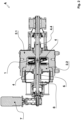
- the filtering device (A) shown in Figures 1 , 2 and 3 is suitable for use in a plastic recycling process.
- the filtering device (A) has the task of filtering/stopping the impurities present in the raw plastic material to be recycled with a degree of purity depending on the size of the mesh on the filter element used.
- the raw plastic material to be recycled is first heated and brought to its molten state to then be conveyed to the filtering device (A), in particular to a filtration chamber (1) of the device (A) itself.
- the filtering device (A) comprises a hollow body (2.1) provided with an opening on one side and a cover or bulkhead (2.2) suited to hermetically close said opening in order to define the filtration chamber (1).
- Said hollow body (2.1) has an inlet (2.3), for the introduction of the plastic material in its molten state into the filtration chamber (1) in order to be filtered, and an outlet (2.4) for the discharge of the plastic material in its filtered molten state from the filtration chamber (1).
- Said inlet (2.3) and outlet (2.4) are located on the side walls of said hollow body (2.1) with respect to said cover or bulkhead (2.2), as well as diametrically opposite one (2.3) with respect to the other (2.4).
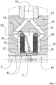
- filtering means suited to divide said filtration chamber (1) into two or more compartments (1a, 1b) of which:
- filtering means (3.1) consisting of two metal meshes (3.1) with openings of an appropriate size placed parallel to each other and suitably spaced from each other.
- Said second compartments (1b) are in communication with said outlet (2.4) directly or, preferably as shown in the example, by auxiliary ducts (2.5).
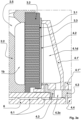
- Each filtering means (3.1) further comprises a first perforated support (3.2) having holes larger than the metal mesh filtering means (3.1).
- This first perforated support (3.2), also called breaker, is suited to support and keep said metal mesh (3.1) flat, since it is subjected to the high thrust pressure of the plastic material in its molten state to be filtered. Said first support (3.2) is placed in said second compartment (1b) directly in contact with said metal mesh (3.1).
- said cleaning device (4) is suited to slide on the surface facing said first compartment (1a) of each second perforated support (3.3) and to collect the impurities collected by said metal meshes (3.1).
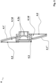
- Figures 4a, 4b , and 5 show various views of said cleaning device (4), comprising two main hollow bodies (4.1', 4.1"), two adhering walls (4.2) to said metal meshes (3.1) of said filtering means (3.1), connecting elements (4.3) with moving means (4.4).
- These moving means (4.4) consist, in this example, of a rotation and centering shaft (4.4), shown in Figures 1 , 2 , 3 .
- Said rotation and centering shaft (4.4) has at least one non-circular section.
- Figures 4a and 4b show two axonometric views of the cleaning device (4)
- Figure 5 shows a section of the cleaning device (4)
- Figure 6 shows an axonometric view of the various parts (4.1'. 4.1", 4.2, 4.3) of the cleaning device (4).
- Each main body (4.1', 4.1") comprises, in turn, a first generally cylindrical part (4.1a), a second substantially flat or parallelepipedal part (4.1b) generally radial with respect to said cylindrical part (4.1a), a third part (4.1c) generally triangular connecting said first part (4.1a) and said second part (4.1b).
- each main body (4.1', 4.1) has elements, parts, and structures for the coaxial coupling with the first part (4.1a) of the other main body (4.1', 4.1") in such a way as to prevent their reciprocal rotation but enable their reciprocal translation along the common axis of rotation (6, 4.4).
- each main body (4.1', 4.1" has a seat (4.1s) for housing and fixing one of said adhering walls (4.2).
- said third part (4.1c) of each main body (4.1', 4.2") has a duct (4.1d) suited to connect said seat (4.1s) of said second part (4.1b) with the internal space of said first generally cylindrical part (4.1a).
- Said two main bodies (4.1', 4.1") are identical, and suited to be coupled to each other in a specular manner so that their second parts (4.1b) are opposed, both diametrically with respect to the axis of said first coupling parts (4.1a), with the seat (4.1s) of each second part (4.1b) facing the direction opposite the opposite second part (4.1b).
- Said two main bodies (4.1', 4.1") are such that, when they are coupled one facing the other, their internal ducts (4.1d) of said first generally cylindrical part (4.1a) are opposite and coaxial.
- Each adhering wall (4.2) consists of a sheet or plate suited to be housed in the corresponding seat (4.1s) of a second part (4.1b).
- each said adhering wall (4.2) is suited to be placed in contact with said second perforated support (3.3) of a metal mesh of the filtering means (3.1) and has a slit or opening (4.2a) substantially radial with respect to the axis of each main body (4.1', 4.1").
- connection element (4.3) consists of a generically cylindrical element, suited to couple coaxially with said first parts (4.1a) of said main bodies (4.1', 4.1") and coaxially with said rotation and centering shaft (4.4).
- connection element (4.3) has its outer surface (4.3a) suited to obliquely create the rotation of said main bodies (4.1', 4.1") coupled to each other, and also has at least part of its inner surface (4.3b) suited to couple with said rotation and centering shaft (4.4).
- the shape of the outer surface (4.3a) and the inner surface (4.3b) of said connection member is polygonal, more specifically, hexagonal.
- connection element (4.3) also has at least one hole, groove or duct (4.3c) suited to connect the outer surface (4.3a) of the connection element (4.3) with its inner surface (4.3b) so that the duct (4.1d) of said first parts (4.1a) of said main bodies (4.1', 4.1") is connected with the inner surface (4.3b) of said connection element (4.3).
- connection element (4.3) has two opposing ducts (4.3c) suited to be aligned and in communication with the respective ducts (4.1d) of said two coupled main bodies (4.1', 4.1").
- the rotation and centering shaft (4.4) consists of a shaft (4.4) passing through the hollow body (2.1), a filtering means (3.1), and the relative pair of perforated supports (3.2, 3.3).
- Said rotation and centering shaft (4.4) is suited to be connected with an electric motor (5), outside said hollow body (2.1), and with said connection element (4.3), inside said hollow body (2.1) so as to rotate said connection element (4.3) and the entire cleaning device (4).
- said rotation and centering shaft (4.4) extends from the outside of said hollow body (2.1) up to about half the length of said connection element (4.3), without reaching said hole, groove or duct (4.3c) of said connection element (4.3).
- the discharge device (6) of said impurities collected by said cleaning device (4) comprises a shaft (6) with an external helical groove (6.1) or screw suited to connect the internal surface (4.3b) of said connection element (4.3) communicating with its hole, groove or duct (4.3c) with a discharge opening (8) outside the filtration chamber (1).
- said shaft (6) with external helical groove (6.1) is coaxial with said rotation and centering shaft (4.4) and extends from the inside of said connection element (4.3) up to a discharge opening (8) outside said hollow body (2.1).
- Said shaft (6) with external groove (6.1) of said discharge device (6) is connected to an electric motor (7), outside said hollow body (2.1).
- the plastic material introduced into the new filtration device (A) is filtered by two filtering means (3.1), obtaining a higher filtration efficiency than the filtration devices of equivalent size of the prior art.
- the filtered plastic material which already passed through said filtering means (3.1) into the second compartments (1.b) of the filtration chamber (1) has considerable pressure, it exerts a counter pressure on the filtering means (3.1) removing the impurities from the filtering means (3.1) through said second perforated supports (3.3) towards the first compartment (1a) of the filtration chamber (1), and through said slit or opening (4.2a) of the adhering wall (4.2) of the cleaning device (4) from which it is discharged.
- each main body (4.1', 4.1") From the inside of each main body (4.1', 4.1") the material removed by the filtering means (3.1) flows into the connection element (4.3) and from there it flows into the external helical groove (6.1) of the shaft of the discharge device (6) which moves it away towards said discharge opening (8) outside the filtration chamber (1).
- Said main bodies (4.1', 4.1") of the cleaning device (4) are continuously rotated on the surface of said filtering means (3.1) by the relative rotation and centering shaft (4.4) and by the relative electric motor (5).
- the adjustment of the rotation speed of the main bodies (4.1', 4.1") of the cleaning device (4) and the rotation speed of the shaft of the discharge device (6) allows all the material collected by said filtering means (3.1) to be discharged limiting the loss of useful material to be filtered, as well as regulating the pressure of the plastic material to be filtered.
- the pressure of the plastic material to be filtered is measured inside the first compartment (1a) of the filtration chamber (1).
- this pressure increases and reaches a threshold, it is an indication that the metal mesh (3.1) of the filtering means (3.1) is clogged by the filtered impurities and consequently the rotation speeds of both the cleaning device (4) and the discharge device (6) are regulated to keep said pressure constant inside the first compartment (1a) of the filtration chamber (1).
- the impurities are adequately removed from the metal meshes (3.1) and from the second perforated supports (3.3), limiting the loss of plastic material.
- connection element (4.3) intended to remove the impurities collected by the cleaning device (4) are aligned and opposing and are both in continuous communication with the helical groove (6.1) of the shaft (6) of the discharge device (6).
- the rotational speed of the discharge device (6), directly proportional to the discharge flow rate, and the rotational speed of the cleaning device (4) are related so as to enable all the contaminated material and the impurities accumulated in the second perforated supports (3.3) that are facing the slit or opening (4.2a) of each said adhering wall (4.2) to be completely removed from the cleaning device (4).
- each main body (4.1', 4.1") of the cleaning device (4) means that the pressure of the plastic material to be filtered keeps each said main body (4.1', 4.1") and each relative adhering wall (4.2) properly and constantly adhering to each relative second perforated support (3.3).
- the discharge device (6) generates, in its rotation, a controlled discharge flow rate making the counter pressure just a support factor.
- each said adhering wall (4.2) and each second perforated support (3.3) have a shape, dimensions, and gap, such as to be able to continuously work and draw in only the contaminated material minimizing the loss of useful plastic material while maintaining the pressure constant.
- the new cleaning system described above enables the removal of even small controlled volumes of only the material to be eliminated, allowing work with highly contaminated materials while minimizing the waste of useful plastic material.
Landscapes
- Engineering & Computer Science (AREA)
- Mechanical Engineering (AREA)
- Extrusion Moulding Of Plastics Or The Like (AREA)
Claims (7)
- Filtervorrichtung (A) für Kunststoffmaterial im geschmolzenen Zustand, wobei die besagte Filtervorrichtung (A) Folgendes umfasst:- einen Hohlkörper (2.1), der mit einer Mündung und einem Deckel (2.1) versehen ist, der dazu geeignet ist, der besagten Mündung zugeordnet zu werden, um eine Filterkammer (1) zu definieren;- mindestens einen Einlassweg (2.3) für die Einleitung des besagten Kunststoffmaterials im geschmolzenen Zustand in die besagte Filterkammer (1) und mindestens einen Auslassweg (2.4) für die Ableitung des gefilterten Kunststoffmaterials im geschmolzenen Zustand aus der besagten Filterkammer (1);- zwei Filtermittel (3.1), die aus einem Metallgewebe bestehen und nebeneinander in der besagten Filterkammer (1) angeordnet sind, wobei die besagten Filtermittel (3.1) einen ersten Innenraum (1a), der direkt mit dem besagten Einlassweg (2.3) kommuniziert, und mindestens einen zweiten Innenraum (1b), der mit dem besagten Auslassweg (2.4) kommuniziert, definieren;- einen ersten Lochträger (3.2) und einen zweiten Lochträger (3.3), wobei jeder erste Lochträger und jeder zweite Lochträger (3.2, 3.3) so angeordnet ist, dass er an einer der beiden Seiten jedes Filtermittels (3.1) anhaftet, wobei die Löcher des besagten ersten Lochträgers und des besagten zweiten Lochträgers (3.2, 3.3) größer sind als die Maschenweiten des Filtermittels, das aus einem Metallgewebe (3.1) besteht;- eine Reinigungsvorrichtung (4), die im besagten ersten Innenraum (1a) zwischen den besagten beiden Filtermitteln (3.1) angeordnet ist;- eine Entleerungsvorrichtung (6, 7), die dazu geeignet ist, die besagten von der besagten Reinigungsvorrichtung (4) gesammelten Verunreinigungen zu einem Entleerungsauslass (8) abzuleiten, wobei die besagte Entleerungsvorrichtung (6, 7) zentral in Bezug auf die besagte Reinigungsvorrichtung (4) angeordnet ist;
dadurch gekennzeichnet, dass die besagte Reinigungsvorrichtung (4) Folgendes umfasst:ein oder mehrere Paare von Haupthohlkörpern (4.1', 4.1"), ein oder mehrere Paare von anhaftenden Wänden (4.2), die an den besagten zweiten Lochträgern (3.3) anhaften, und Bewegungsmittel (4.4), und wobei jeder Haupthohlkörper (4.1', 4.1") dazu geeignet ist, mit einem anderen Haupthohlkörper (4.1", 4.1') in einer Position diametral gegenüber letzterem und in einer solchen Weise gekoppelt zu werden, dass sie sich einstückig miteinander drehen und entlang der gemeinsamen Achse frei verschiebbar sind, und wobei jeder Haupthohlkörper (4.1', 4.1") dazu geeignet ist, jede der besagten anhaftenden Wände (4.2) zu tragen, sodass sie an der Oberfläche des entsprechenden zweiten Lochträgers (3.3) eines Filtermittels (3.1) haften bleibt, und wobei jede anhaftende Wand (4.2) mit einem Schlitz oder einer Öffnung (4.2a) versehen ist, der/die dazu geeignet ist, die Oberfläche der besagten anhaftenden Wand (4.2), die in Kontakt mit dem zweiten Lochträger (3.3) ist, mit dem Inneren des Haupthohlkörpers (4.1', 4.1"), mit dem die besagte anhaftende Wand (4.2) verbunden ist, in Kommunikation zu bringen, und wobei die besagten Haupthohlkörper (4.1', 4.1") mit einem inneren Verbindungskanal (4.1d) versehen sind, der dazu geeignet ist, den Sitz (4.1s) der besagten anhaftenden Wand (4.2), das Innere jedes Haupthohlkörpers (4.1', 4.1") und das Innere ihres zentralen gegenseitigen Kopplungsteils (4.1a) zu verbinden. - Vorrichtung (A) nach Patentanspruch 1, dadurch gekennzeichnet, dass die besagten Haupthohlkörper (4.1', 4.1") der besagten Reinigungsvorrichtung (4) durch eine Dreh- und Zentrierwelle (4.4), die durch motorisierte Mittel (5) angetrieben wird, in Drehung versetzt werden.
- Vorrichtung (A) nach den vorhergehenden Patentansprüchen, dadurch gekennzeichnet, dass die besagte Entleerungsvorrichtung (6), die dazu geeignet ist, die besagten von der besagten Reinigungsvorrichtung (4) gesammelten Verunreinigungen abzuleiten, eine Welle (6) mit einer äußeren Spiralnut (6.1), oder Spiralschraube, umfasst, die dazu geeignet ist, das Innere des zentralen Teils (4.1a), der die besagten Haupthohlkörper (4.1', 4.1") miteinander koppelt, mit einer Ableitungsöffnung (8), die sich außerhalb der Filterkammer (1) befindet, zu verbinden.
- Vorrichtung (A) nach den vorhergehenden Patentansprüchen, dadurch gekennzeichnet, dass sie ein Verbindungselement (4.3) umfasst, das aus einem allgemein zylindrischen Element besteht, das dazu geeignet ist, mit den besagten ersten zentralen Teilen (4.1a) der besagten Hauptkörper (4.1', 4.1") gekoppelt und koaxial daran befestigt zu werden und mit der besagten Dreh- und Zentrierwelle (4.4) gekoppelt und koaxial daran befestigt zu werden, und wobei das besagte Verbindungselement (4.3) mit einem oder mehreren Paaren von Löchern, Nuten oder Kanälen (4.3c) versehen ist, die auf derselben Ebene liegen, die orthogonal zur besagten Dreh- und Zentrierwelle (4.4) ist, und wobei die Löcher, Nuten oder Kanäle (4.3c) jedes Paares gemäß einer zentralen Symmetrie in Bezug auf die Dreh- und Zentrierwelle (4.4) angeordnet sind und dazu geeignet sind, die Außenfläche (4.3a) und die Innenfläche (4.3b) des Verbindungselements (4.3) selbst so zu verbinden, dass jeder Kanal (4.1d) der besagten ersten zentralen Teile (4.1a) der besagten Hauptkörper (4.1', 4.1") mit der Innenfläche (4.3b) des besagten Verbindungselements (4.3) und mit der besagten äußeren Spiralnut (6.1) der besagten Welle (6), oder Spiralschraube, der besagten Entleerungsvorrichtung (6) verbunden wird.
- Vorrichtung (A) nach den vorhergehenden Patentansprüchen, dadurch gekennzeichnet, dass sowohl die Auslasswege (2.4) für das gefilterte Material als auch die gegenseitige Position und Anordnung der Hauptkörper (4.1', 4.1") der Reinigungsvorrichtung (4) in Bezug auf die besagten Filtermittel (3.1) gleich sind und dazu geeignet sind, im Wesentlichen den gleichen Druck auf alle Hauptkörper (4.1', 4.1") und den gleichen Druck des aus den besagten Filtermitteln (3.1) austretenden gefilterten Materials aufrechtzuerhalten.
- Vorrichtung (A) nach den vorhergehenden Patentansprüchen, dadurch gekennzeichnet, dass die Gänge oder Kanäle (4.1d) der besagten Hauptkörper (4.1', 4.1") den gleichen Querschnitt aufweisen, und wobei die besagten Kanäle (4.3c) des besagten Verbindungselements (4.3) in identischer und symmetrischer Weise in die besagte Entleerungsvorrichtung (6) münden, sodass der Fluss der von den anhaftenden Wänden (4.2) und den Hauptkörpern (4.1', 4.1") der besagten Reinigungsvorrichtung (4) gesammelten Verunreinigungen zur besagten Entleerungsvorrichtung (6) und zur besagten Ableitungsöffnung (8) identisch bleibt.
- Vorrichtung (A) nach den vorhergehenden Patentansprüchen, dadurch gekennzeichnet, dass die Drehgeschwindigkeit der Reinigungsvorrichtung (4) und der Entleerungsvorrichtung (6) reguliert wird, um die Entleerung von nützlichem Material, das zusammen mit den Verunreinigungen entfernt wird, zu minimieren und einen konstanten Druck im Inneren der Filterkammer (1) aufrechtzuerhalten.
Applications Claiming Priority (2)
| Application Number | Priority Date | Filing Date | Title |
|---|---|---|---|
| IT202100023948 | 2021-09-17 | ||
| PCT/IB2022/056319 WO2023041996A1 (en) | 2021-09-17 | 2022-07-08 | Filtering device for molten polymeric materials with counterflow cleaning system |
Publications (3)
| Publication Number | Publication Date |
|---|---|
| EP4401943A1 EP4401943A1 (de) | 2024-07-24 |
| EP4401943C0 EP4401943C0 (de) | 2025-05-07 |
| EP4401943B1 true EP4401943B1 (de) | 2025-05-07 |
Family
ID=78771039
Family Applications (1)
| Application Number | Title | Priority Date | Filing Date |
|---|---|---|---|
| EP22748434.2A Active EP4401943B1 (de) | 2021-09-17 | 2022-07-08 | Filtervorrichtung für geschmolzene polymere materialien mit gegenstromreinigungssystem |
Country Status (3)
| Country | Link |
|---|---|
| US (1) | US12403642B2 (de) |
| EP (1) | EP4401943B1 (de) |
| WO (1) | WO2023041996A1 (de) |
Family Cites Families (5)
| Publication number | Priority date | Publication date | Assignee | Title |
|---|---|---|---|---|
| DE3239030A1 (de) * | 1981-10-28 | 1983-09-29 | Gail, Josef, 8890 Aichach | Vorrichtung zum trennen von materialien unterschiedlicher konsistenz |
| AT399844B (de) * | 1993-10-19 | 1995-07-25 | Bacher Helmut | Filtervorrichtung, insbesondere für thermoplastische kunststoffschmelzen |
| AT413497B (de) * | 2004-10-25 | 2006-03-15 | Erema | Vorrichtung zum kontinuierlichen filtern von fliessfähigen massen, die feststoffteilchen enthalten |
| CN105058735A (zh) * | 2015-07-31 | 2015-11-18 | 马锡林 | 塑料挤出机的高效无丝网过滤装置 |
| DE202017007054U1 (de) * | 2017-04-05 | 2019-05-10 | Maag Automatik Gmbh | Filteranordnung für Fluid |
-
2022
- 2022-07-08 WO PCT/IB2022/056319 patent/WO2023041996A1/en not_active Ceased
- 2022-07-08 US US18/692,811 patent/US12403642B2/en active Active
- 2022-07-08 EP EP22748434.2A patent/EP4401943B1/de active Active
Also Published As
| Publication number | Publication date |
|---|---|
| EP4401943C0 (de) | 2025-05-07 |
| WO2023041996A1 (en) | 2023-03-23 |
| US12403642B2 (en) | 2025-09-02 |
| US20240375338A1 (en) | 2024-11-14 |
| EP4401943A1 (de) | 2024-07-24 |
Similar Documents
| Publication | Publication Date | Title |
|---|---|---|
| EP0546308B1 (de) | Filtrationssystem | |
| US10786763B2 (en) | Filter for extruder press | |
| CA2661222A1 (en) | An apparatus for the continuous filtering of impurities from a flowable compound | |
| JP6738168B2 (ja) | フィルタユニット、それを有するフィルタチップコンベア、および、フィルタチップコンベアによる濾過方法 | |
| JP3727210B2 (ja) | 濾過装置 | |
| EP2468379B1 (de) | Filtervorrichtung | |
| US20100200479A1 (en) | Molten plastic material filtration apparatus | |
| KR102380488B1 (ko) | 역세척이 가능한 회전 여과식 수처리장치 | |
| KR101594678B1 (ko) | 합성수지 용융압출기의 여과판 막힘 방지장치 | |
| EP3370848B1 (de) | Saugkasten, bandfilter, verfahren zur wartung eines vakuumbandfilters, verfahren für die fest/flüssig-trennung von schlamm und filterelement | |
| JP5519697B2 (ja) | 食品処理で使用するフィルタ | |
| US20240278153A1 (en) | Filtering device for plastic materials with cleaning system | |
| EP4401943B1 (de) | Filtervorrichtung für geschmolzene polymere materialien mit gegenstromreinigungssystem | |
| KR20250012621A (ko) | 필터 조립체 | |
| CN211912899U (zh) | 手摇在线过滤装置 | |
| ITVI940101A1 (it) | Dispositivo di filtrazione per la separazione di materiali inquinanti da masse plastiche fuse in presse per l'estrusione di materiali plastici riciclati. | |
| CN117162438B (zh) | 一种高耐磨矿浆输送用橡胶软管用生产设备及其使用方法 | |
| KR100333481B1 (ko) | 자동정화식 진공탈기장치 | |
| CN213790312U (zh) | 一种工业陶瓷结构件生产用浆料过滤装置 | |
| US20230311030A1 (en) | Roller filtration apparatus | |
| JPH0416204A (ja) | 回転固液分離装置 | |
| ITRM20120626A1 (it) | Macchina per il trattamento di acque reflue a dischi filtranti |
Legal Events
| Date | Code | Title | Description |
|---|---|---|---|
| STAA | Information on the status of an ep patent application or granted ep patent |
Free format text: STATUS: UNKNOWN |
|
| STAA | Information on the status of an ep patent application or granted ep patent |
Free format text: STATUS: THE INTERNATIONAL PUBLICATION HAS BEEN MADE |
|
| PUAI | Public reference made under article 153(3) epc to a published international application that has entered the european phase |
Free format text: ORIGINAL CODE: 0009012 |
|
| STAA | Information on the status of an ep patent application or granted ep patent |
Free format text: STATUS: REQUEST FOR EXAMINATION WAS MADE |
|
| 17P | Request for examination filed |
Effective date: 20240312 |
|
| AK | Designated contracting states |
Kind code of ref document: A1 Designated state(s): AL AT BE BG CH CY CZ DE DK EE ES FI FR GB GR HR HU IE IS IT LI LT LU LV MC MK MT NL NO PL PT RO RS SE SI SK SM TR |
|
| DAV | Request for validation of the european patent (deleted) | ||
| DAX | Request for extension of the european patent (deleted) | ||
| GRAP | Despatch of communication of intention to grant a patent |
Free format text: ORIGINAL CODE: EPIDOSNIGR1 |
|
| STAA | Information on the status of an ep patent application or granted ep patent |
Free format text: STATUS: GRANT OF PATENT IS INTENDED |
|
| INTG | Intention to grant announced |
Effective date: 20250218 |
|
| GRAS | Grant fee paid |
Free format text: ORIGINAL CODE: EPIDOSNIGR3 |
|
| GRAA | (expected) grant |
Free format text: ORIGINAL CODE: 0009210 |
|
| STAA | Information on the status of an ep patent application or granted ep patent |
Free format text: STATUS: THE PATENT HAS BEEN GRANTED |
|
| AK | Designated contracting states |
Kind code of ref document: B1 Designated state(s): AL AT BE BG CH CY CZ DE DK EE ES FI FR GB GR HR HU IE IS IT LI LT LU LV MC MK MT NL NO PL PT RO RS SE SI SK SM TR |
|
| REG | Reference to a national code |
Ref country code: GB Ref legal event code: FG4D |
|
| REG | Reference to a national code |
Ref country code: CH Ref legal event code: EP |
|
| REG | Reference to a national code |
Ref country code: DE Ref legal event code: R096 Ref document number: 602022014397 Country of ref document: DE |
|
| REG | Reference to a national code |
Ref country code: IE Ref legal event code: FG4D |
|
| U01 | Request for unitary effect filed |
Effective date: 20250508 |
|
| U07 | Unitary effect registered |
Designated state(s): AT BE BG DE DK EE FI FR IT LT LU LV MT NL PT RO SE SI Effective date: 20250516 |
|
| U20 | Renewal fee for the european patent with unitary effect paid |
Year of fee payment: 4 Effective date: 20250728 |
|
| PG25 | Lapsed in a contracting state [announced via postgrant information from national office to epo] |
Ref country code: ES Free format text: LAPSE BECAUSE OF FAILURE TO SUBMIT A TRANSLATION OF THE DESCRIPTION OR TO PAY THE FEE WITHIN THE PRESCRIBED TIME-LIMIT Effective date: 20250507 |
|
| PG25 | Lapsed in a contracting state [announced via postgrant information from national office to epo] |
Ref country code: NO Free format text: LAPSE BECAUSE OF FAILURE TO SUBMIT A TRANSLATION OF THE DESCRIPTION OR TO PAY THE FEE WITHIN THE PRESCRIBED TIME-LIMIT Effective date: 20250807 Ref country code: GR Free format text: LAPSE BECAUSE OF FAILURE TO SUBMIT A TRANSLATION OF THE DESCRIPTION OR TO PAY THE FEE WITHIN THE PRESCRIBED TIME-LIMIT Effective date: 20250808 |
|
| PG25 | Lapsed in a contracting state [announced via postgrant information from national office to epo] |
Ref country code: PL Free format text: LAPSE BECAUSE OF FAILURE TO SUBMIT A TRANSLATION OF THE DESCRIPTION OR TO PAY THE FEE WITHIN THE PRESCRIBED TIME-LIMIT Effective date: 20250507 |
|
| PG25 | Lapsed in a contracting state [announced via postgrant information from national office to epo] |
Ref country code: HR Free format text: LAPSE BECAUSE OF FAILURE TO SUBMIT A TRANSLATION OF THE DESCRIPTION OR TO PAY THE FEE WITHIN THE PRESCRIBED TIME-LIMIT Effective date: 20250507 |
|
| PG25 | Lapsed in a contracting state [announced via postgrant information from national office to epo] |
Ref country code: RS Free format text: LAPSE BECAUSE OF FAILURE TO SUBMIT A TRANSLATION OF THE DESCRIPTION OR TO PAY THE FEE WITHIN THE PRESCRIBED TIME-LIMIT Effective date: 20250807 |
|
| PG25 | Lapsed in a contracting state [announced via postgrant information from national office to epo] |
Ref country code: IS Free format text: LAPSE BECAUSE OF FAILURE TO SUBMIT A TRANSLATION OF THE DESCRIPTION OR TO PAY THE FEE WITHIN THE PRESCRIBED TIME-LIMIT Effective date: 20250907 |
|
| PG25 | Lapsed in a contracting state [announced via postgrant information from national office to epo] |
Ref country code: SM Free format text: LAPSE BECAUSE OF FAILURE TO SUBMIT A TRANSLATION OF THE DESCRIPTION OR TO PAY THE FEE WITHIN THE PRESCRIBED TIME-LIMIT Effective date: 20250507 |
|
| PG25 | Lapsed in a contracting state [announced via postgrant information from national office to epo] |
Ref country code: CZ Free format text: LAPSE BECAUSE OF FAILURE TO SUBMIT A TRANSLATION OF THE DESCRIPTION OR TO PAY THE FEE WITHIN THE PRESCRIBED TIME-LIMIT Effective date: 20250507 |
|
| PG25 | Lapsed in a contracting state [announced via postgrant information from national office to epo] |
Ref country code: SK Free format text: LAPSE BECAUSE OF FAILURE TO SUBMIT A TRANSLATION OF THE DESCRIPTION OR TO PAY THE FEE WITHIN THE PRESCRIBED TIME-LIMIT Effective date: 20250507 |
|
| REG | Reference to a national code |
Ref country code: CH Ref legal event code: H13 Free format text: ST27 STATUS EVENT CODE: U-0-0-H10-H13 (AS PROVIDED BY THE NATIONAL OFFICE) Effective date: 20260224 |
|
| PLBE | No opposition filed within time limit |
Free format text: ORIGINAL CODE: 0009261 |
|
| STAA | Information on the status of an ep patent application or granted ep patent |
Free format text: STATUS: NO OPPOSITION FILED WITHIN TIME LIMIT |
|
| REG | Reference to a national code |
Ref country code: CH Ref legal event code: L10 Free format text: ST27 STATUS EVENT CODE: U-0-0-L10-L00 (AS PROVIDED BY THE NATIONAL OFFICE) Effective date: 20260318 |