EP3370848B1 - Saugkasten, bandfilter, verfahren zur wartung eines vakuumbandfilters, verfahren für die fest/flüssig-trennung von schlamm und filterelement - Google Patents
Saugkasten, bandfilter, verfahren zur wartung eines vakuumbandfilters, verfahren für die fest/flüssig-trennung von schlamm und filterelement Download PDFInfo
- Publication number
- EP3370848B1 EP3370848B1 EP16861672.0A EP16861672A EP3370848B1 EP 3370848 B1 EP3370848 B1 EP 3370848B1 EP 16861672 A EP16861672 A EP 16861672A EP 3370848 B1 EP3370848 B1 EP 3370848B1
- Authority
- EP
- European Patent Office
- Prior art keywords
- vacuum
- filter
- vacuum box
- station
- suction
- Prior art date
- Legal status (The legal status is an assumption and is not a legal conclusion. Google has not performed a legal analysis and makes no representation as to the accuracy of the status listed.)
- Active
Links
- 239000002002 slurry Substances 0.000 title claims description 26
- 238000000034 method Methods 0.000 title claims description 19
- 238000000926 separation method Methods 0.000 title claims description 16
- 239000007787 solid Substances 0.000 title claims description 15
- 238000009826 distribution Methods 0.000 claims description 64
- 239000012530 fluid Substances 0.000 claims description 42
- 230000000903 blocking effect Effects 0.000 claims description 40
- 239000000706 filtrate Substances 0.000 claims description 21
- 239000000919 ceramic Substances 0.000 claims description 13
- 238000004891 communication Methods 0.000 claims description 11
- 239000011148 porous material Substances 0.000 claims description 9
- 238000005507 spraying Methods 0.000 claims description 8
- 206010007191 Capillary fragility Diseases 0.000 claims description 5
- 239000007921 spray Substances 0.000 claims description 5
- 239000012065 filter cake Substances 0.000 description 30
- 238000001914 filtration Methods 0.000 description 21
- XLYOFNOQVPJJNP-UHFFFAOYSA-N water Substances O XLYOFNOQVPJJNP-UHFFFAOYSA-N 0.000 description 21
- 238000005406 washing Methods 0.000 description 14
- 238000010276 construction Methods 0.000 description 13
- 239000007788 liquid Substances 0.000 description 13
- 239000011449 brick Substances 0.000 description 11
- 239000000463 material Substances 0.000 description 11
- 239000007789 gas Substances 0.000 description 10
- 238000011001 backwashing Methods 0.000 description 9
- 238000013461 design Methods 0.000 description 9
- 238000004140 cleaning Methods 0.000 description 8
- 229910010293 ceramic material Inorganic materials 0.000 description 6
- 238000005304 joining Methods 0.000 description 6
- 239000004033 plastic Substances 0.000 description 6
- 230000009471 action Effects 0.000 description 5
- 239000004744 fabric Substances 0.000 description 5
- 230000008569 process Effects 0.000 description 5
- 239000000126 substance Substances 0.000 description 5
- 230000000694 effects Effects 0.000 description 4
- 239000012528 membrane Substances 0.000 description 4
- 239000002253 acid Substances 0.000 description 3
- 238000005260 corrosion Methods 0.000 description 3
- 230000007797 corrosion Effects 0.000 description 3
- 238000004519 manufacturing process Methods 0.000 description 3
- 230000000717 retained effect Effects 0.000 description 3
- 239000002028 Biomass Substances 0.000 description 2
- XEEYBQQBJWHFJM-UHFFFAOYSA-N Iron Chemical compound [Fe] XEEYBQQBJWHFJM-UHFFFAOYSA-N 0.000 description 2
- 244000261422 Lysimachia clethroides Species 0.000 description 2
- GWEVSGVZZGPLCZ-UHFFFAOYSA-N Titan oxide Chemical compound O=[Ti]=O GWEVSGVZZGPLCZ-UHFFFAOYSA-N 0.000 description 2
- 150000007513 acids Chemical class 0.000 description 2
- 238000004026 adhesive bonding Methods 0.000 description 2
- 230000008901 benefit Effects 0.000 description 2
- 238000005265 energy consumption Methods 0.000 description 2
- 229910052751 metal Inorganic materials 0.000 description 2
- 239000002184 metal Substances 0.000 description 2
- 239000002245 particle Substances 0.000 description 2
- 230000008439 repair process Effects 0.000 description 2
- 230000001360 synchronised effect Effects 0.000 description 2
- 238000012546 transfer Methods 0.000 description 2
- 238000011144 upstream manufacturing Methods 0.000 description 2
- 239000005995 Aluminium silicate Substances 0.000 description 1
- 241000195493 Cryptophyta Species 0.000 description 1
- 229920001131 Pulp (paper) Polymers 0.000 description 1
- PNEYBMLMFCGWSK-UHFFFAOYSA-N aluminium oxide Inorganic materials [O-2].[O-2].[O-2].[Al+3].[Al+3] PNEYBMLMFCGWSK-UHFFFAOYSA-N 0.000 description 1
- PZZYQPZGQPZBDN-UHFFFAOYSA-N aluminium silicate Chemical compound O=[Al]O[Si](=O)O[Al]=O PZZYQPZGQPZBDN-UHFFFAOYSA-N 0.000 description 1
- 229910000323 aluminium silicate Inorganic materials 0.000 description 1
- 235000012211 aluminium silicate Nutrition 0.000 description 1
- 239000007795 chemical reaction product Substances 0.000 description 1
- 239000012141 concentrate Substances 0.000 description 1
- 238000010924 continuous production Methods 0.000 description 1
- 229910052593 corundum Inorganic materials 0.000 description 1
- 230000001419 dependent effect Effects 0.000 description 1
- 238000001035 drying Methods 0.000 description 1
- 239000010408 film Substances 0.000 description 1
- 239000010419 fine particle Substances 0.000 description 1
- 230000005484 gravity Effects 0.000 description 1
- 239000012535 impurity Substances 0.000 description 1
- 230000003455 independent Effects 0.000 description 1
- 229910052742 iron Inorganic materials 0.000 description 1
- 239000007791 liquid phase Substances 0.000 description 1
- 238000002844 melting Methods 0.000 description 1
- 230000008018 melting Effects 0.000 description 1
- 239000000203 mixture Substances 0.000 description 1
- 230000004048 modification Effects 0.000 description 1
- 238000012986 modification Methods 0.000 description 1
- 239000011368 organic material Substances 0.000 description 1
- 239000010815 organic waste Substances 0.000 description 1
- 230000035699 permeability Effects 0.000 description 1
- 231100000614 poison Toxicity 0.000 description 1
- 230000007096 poisonous effect Effects 0.000 description 1
- 238000003825 pressing Methods 0.000 description 1
- 239000002994 raw material Substances 0.000 description 1
- 150000003839 salts Chemical class 0.000 description 1
- 239000010802 sludge Substances 0.000 description 1
- 229920001169 thermoplastic Polymers 0.000 description 1
- 239000012815 thermoplastic material Substances 0.000 description 1
- 239000004416 thermosoftening plastic Substances 0.000 description 1
- 238000004148 unit process Methods 0.000 description 1
- 239000002699 waste material Substances 0.000 description 1
- 229910001845 yogo sapphire Inorganic materials 0.000 description 1
Images


Classifications
-
- B—PERFORMING OPERATIONS; TRANSPORTING
- B01—PHYSICAL OR CHEMICAL PROCESSES OR APPARATUS IN GENERAL
- B01D—SEPARATION
- B01D29/00—Filters with filtering elements stationary during filtration, e.g. pressure or suction filters, not covered by groups B01D24/00 - B01D27/00; Filtering elements therefor
- B01D29/09—Filters with filtering elements stationary during filtration, e.g. pressure or suction filters, not covered by groups B01D24/00 - B01D27/00; Filtering elements therefor with filtering bands, e.g. movable between filtering operations
-
- B—PERFORMING OPERATIONS; TRANSPORTING
- B01—PHYSICAL OR CHEMICAL PROCESSES OR APPARATUS IN GENERAL
- B01D—SEPARATION
- B01D33/00—Filters with filtering elements which move during the filtering operation
- B01D33/056—Construction of filtering bands or supporting belts, e.g. devices for centering, mounting or sealing the filtering bands or the supporting belts
-
- B—PERFORMING OPERATIONS; TRANSPORTING
- B01—PHYSICAL OR CHEMICAL PROCESSES OR APPARATUS IN GENERAL
- B01D—SEPARATION
- B01D29/00—Filters with filtering elements stationary during filtration, e.g. pressure or suction filters, not covered by groups B01D24/00 - B01D27/00; Filtering elements therefor
- B01D29/50—Filters with filtering elements stationary during filtration, e.g. pressure or suction filters, not covered by groups B01D24/00 - B01D27/00; Filtering elements therefor with multiple filtering elements, characterised by their mutual disposition
-
- B—PERFORMING OPERATIONS; TRANSPORTING
- B01—PHYSICAL OR CHEMICAL PROCESSES OR APPARATUS IN GENERAL
- B01D—SEPARATION
- B01D29/00—Filters with filtering elements stationary during filtration, e.g. pressure or suction filters, not covered by groups B01D24/00 - B01D27/00; Filtering elements therefor
- B01D29/96—Filters with filtering elements stationary during filtration, e.g. pressure or suction filters, not covered by groups B01D24/00 - B01D27/00; Filtering elements therefor in which the filtering elements are moved between filtering operations; Particular measures for removing or replacing the filtering elements; Transport systems for filters
-
- B—PERFORMING OPERATIONS; TRANSPORTING
- B01—PHYSICAL OR CHEMICAL PROCESSES OR APPARATUS IN GENERAL
- B01D—SEPARATION
- B01D33/00—Filters with filtering elements which move during the filtering operation
- B01D33/15—Filters with filtering elements which move during the filtering operation with rotary plane filtering surfaces
- B01D33/155—Filters with filtering elements which move during the filtering operation with rotary plane filtering surfaces the filtering surface being parallel to the rotation axis
-
- B—PERFORMING OPERATIONS; TRANSPORTING
- B01—PHYSICAL OR CHEMICAL PROCESSES OR APPARATUS IN GENERAL
- B01D—SEPARATION
- B01D33/00—Filters with filtering elements which move during the filtering operation
- B01D33/333—Filters with filtering elements which move during the filtering operation with individual filtering elements moving along a closed path
Definitions
- Filtration is a widely used process in which a solid-liquid mixture, such as a slurry or sludge, is forced against a filtering media, with the solids retaining on the filtering media and the liquid phase passing through.
- the present invention relates more precisely to a vacuum box and a vacuum belt filter.
- Vacuum belt filters are conveyor-type filters widely used in the dewatering of slurries.
- the invention relats further to servicing a vacuum belt filter and to a mehtod for liquid-solid separation of slurry in a belt filter.
- the invention relates further to a filter element.
- With vacuum is here understood a pressure below a surrounding pressure which typically, but not necessarily, is the atmospheric pressure of 1 bar.
- Related documents for the present application are DE 29 17 897 A1 , US 2007/227956 A1 , CN 203 463 731 U and CN 203 082 279 U .
- vacuum source is here meant a source capable of creating into the vacuum boxes a pressure which is below the surrounding pressure, typically below the atmospheric pressure of 1 bar.
- the belt filter, the vacuum box, and the filter element have a construction as defined in the appended, respective independents claims, and the method for servicing and carrying out liquid-solid separation are characterized by the features defined in the respective independent method claims.
- Preferred embodiments of the vacuum belt filter, the vacuum box, the filter element and the method for liquid-solid separation of a slurry are disclosed in the appended, respective dependent claims.
- a capillary filter refers to a filter the structure and/or the material of which enables a certain amount of liquid, such as water, to be retained in the filter by a capillary action despite a differential pressure formed by a gas surrounding the filter.
- the liquid may be retained in the micro-pores provided in the filter.
- a capillary filter enables the liquid to be filtered to easily flow through the filter, but when all free liquid, such as the free liquid entering the filter has passed through the filter, the remaining liquid retained in the filter by the capillary action prevents flow of gas, such as air, through the wet filter.
- a major advantage of the vacuum belt filter, the vacuum box and the filter element of the invention is that they enable liquid-solid separation at low energy costs and the servicing interval of the belt filter is long, because the lifetime of the filters of the belt filter is long.
- the vacuum box of the vacuum belt filter has a simple construction making it, and also the belt filter, easy to build.
- the belt filter can be operated with an extremely small vacuum pump this meaning essential energy savings. Despite this, a high underpressure, i.e. a low absolute pressure, can be created within the vacuum box. Service and repair of the belt filter is easy.
- the vacuum boxes can be replaced individually without a need to replace all the vacuum boxes if one or more of the vacuum boxes is a need of repair. Filtration can continue within the vacuum boxes without continuous vacuum feed.
- the vacuum belt filter according to invention is suitable for long cake drying periods because the length of the belt can be selected freely.
- a total filter media is divided into a large number of vacuum boxes each working as an individual dewatering element.
- the differential pressure responsible for the dewatering is effective over the whole length of the belt from vacuum station to discharge station. This is the most efficient way of achieving lowest cake moisture.
- leakage of air between the filter media and the vacuum box does not appear and a differential pressure over the filter cake is maintained. Hence, as the vacuum source does not have to compensate for leakage, the dewatering of the filter cake is efficient and energy consumption is low.
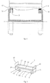
- FIG. 1 illustrates in a side view, one embodiment of the vacuum belt filter according to the invention.
- the vacuum belt filter shown in the drawings is constructed for continuous liquid-solid separation of slurry or similar feed.
- the vacuum belt filter comprises an endless belt 1 comprising a multitude of individual vacuum boxes 2 arranged one after another in the longitudinal direction of the belt.
- the vacuum boxes 2 each comprise a filter means in the form of a capillary filter the filter means preferably being formed of the capillary filter (see filter 7 in Figure 3 ).
- a capillary filter water (liquid) is kept in the micro-pores of the filter medium by the capillary forces and no flow of air takes place after the free water in the residue (e.g. filter cake) has been removed.
- the capillary action of the filter does not participate in the dewatering itself, for instance by sucking water out of the slurry.
- the capillary filter is preferably planar and stiff. With a stiff filter is here meant a rigid filter element which does not collapse inside the vacuum box 2 under the prevailing vacuum conditions, minor deformation being acceptable.
- Reference numeral 29 illustrates a feed station for feeding slurry on the belt 1 of the belt filter.
- Reference numeral 30 shows an inclined chute of the feed station 29 for feeding the slurry on the upper surface of the vacuum boxes 2 and more precisely on the filters thereof.
- the slurry can for example be coarse iron concentrate or organic slurry consisting of fine particles such as organic biomass.
- the vacuum boxes 2 follow one after another along the whole length of the belt 1, but for sake of simplicity, all vacuum boxes have not been illustrated.
- the number of vacuum boxes is dozens and more typically hundreds. No gap is present between adjacent vacuum boxes 2 at the feed station 29. This can e.g. be achieved by arranging a seal (not shown) between the vacuum boxes 2. Such a seal is positioned along one long side of the vacuum box 2.
- lateral shields preventing slurry from falling out laterally from the belt 1 are not shown in Figure 1 .
- These lateral shields, which are mounted on end walls of the vacuum box 2 are, however, seen in Figure 3 , c.f. shields 42, 43.
- the vacuum boxes 2 are arranged on a drive chain 28 of the belt 1 and supported by the drive chain so that they move at synchronized velocity with the drive chain.
- the drive chain 28 replaces the expensive and massive rubber belts known from prior art vacuum belt filters and owing to this, the costs for manufacturing the vacuum belt filter of the present invention are lower. Replacing a rubber belt with a drive chain also lowers the weight of the moving masses of the vacuum belt filter, and as a consequence, less energy is needed for moving the belt and operating the vacuum belt filter.
- Reference numeral 5 shows a suction station for applying suction to the vacuum boxes 2.
- the suction station 5 comprises a rotating distribution valve suction arrangement 24 which for sake of simplicity in the following is also called rotating suction arrangement.
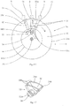
- Figure 15 shows in more detail the rotating suction arrangement 24.
- the rotating suction arrangement 24 comprises a rotating (rotatable) member 25 provided with a plurality of suction ends 26 arranged at a periphery 25a of the rotating member 25.
- the rotating member 25 is preferably circular having a circular periphery 25a, but can more generally be circumferential, i.e. it need not be fully circular having a constant radius.
- a rotating member 25 which is circular enables an easy achievable track for the belt 1 and an easy design of the supports for the belt.
- the rotating member 25 has such suction ends 26 along its entire periphery (360 degrees), but for sake of simplicity only a few suction ends 26 have been drawn in the figure.
- the suction ends 26 are arranged at a distance Z from each other which corresponds to the distance S between outlets 8 of adjacent vacuum boxes 2, c.f. Figure 1 .
- the suction ends 26 are adapted to be connected to the outlets 8 of the vacuum boxes 2 in order to apply suction to the vacuum boxes 2.
- the rotating suction arrangement 24 creates a fluid communication between a vacuum source 45 and the outlet 8 only when the suction ends 26 are connected to the outlet 8 of the vacuum boxes 2.
- the vacuum source 45 comprises a pump (not specifically shown) for creating an underpressure.
- a non-rotatable stationary distribution part 32 is via a connection part 32a (see Figure 12 ) thereof connected to the vacuum source (see reference sign 45 in Figure 1 ) and opens against an inner rim 44b of the rotating member 25 via a suction port 34.
- the inner rim 44b is circular.
- the suction port 34 of the distribution part 32 comprises a suction opening 34a which faces only a part of a multitude of openings 44a provided in the inner rim 44b of the rotating member 25.
- Said inner rim 44b forms a distribution surface 44 comprising said multitude of openings 44a. Adjacent openings 44a are arranged at a constant distance U from one another.
- the rotating member 25 is provided with conduits 35 so that each suction end 26 has its own conduit 35 leading to the suction port 34.
- Each conduit 35 comprises a first end 35a being in fluid communication with a suction end 26, and an opposite second end 35b being in fluid communication with the opening 44a of the inner rim 44b of the rotating member 25.
- the opening 44a of the distribution surface 44 comes into fluid communication with the suction opening 34a of the suction port 34 only at intervals when the rotating member 25 and the distribution surface 44 thereof are rotating.
- the shape and curvature of the suction opening 34a correspond to the shape and curvature of the inner rim 44b of the rotating member 25.
- the suction opening 34a may be bordered with seals 34b so that the suction opening 34a lies tightly and sealingly against the distribution surface 44 of the rotating member 25.
- the suction end 26 in the middle of the three suction ends 26 shown in Figure 14 is connected to the outlet 8 of a vacuum box, and only this suction end 26 applies via i) the suction port 34, ii) the conduit 35 and iii) the suction end 26 a suction to said outlet 8 (i.e. the middle outlet 8 of the shown three outlets 8 in Fig.10 ).
- the conduits 35 are preferably formed of radial channels made in the rotating member 25.
- Reference numeral 33 shows a shaft arranged centrally with respect to the rotating member 25.
- the shaft 33 is supported on bearings (not shown).
- the shaft 33 rotates, also the rotating member 25 rotates and each of the suction ends 26 comes in turn in connection with outlets 8 of the vacuum boxes.
- the shaft can be non-rotatable, whereby the member 25 is arranged to rotate relative to the shaft.
- a rotatable shaft is preferred over a non-rotatable shaft, because bearings mounted at the ends of the shaft are easy to replace (when needed); a shaft fixed to the rotating member 25 is also easy to lathe.
- reference numeral 4 indicates a drive means for driving the belt 1 by driving the drive chain 28 thereof.
- the drive means 4 comprises a turn pulley 4a which has been bearing-mounted on a frame 27 of the vacuum belt filter.
- the frame 27 has been draft with broken line.
- the drive means 4 further comprises a moving apparatus (not shown) for driving the turn pulley 4a of the drive means 4.
- the moving apparatus is preferably electrically driven (an electric motor), because an electric motor enables precise adjustment of speed of the belt 1, which, in turn, improves adjustability of the process.
- the belt 1 can be hydraulically, pneumatically, wind-, water- or biologically powered.
- a hydraulic motor provides rather precise adjustment of speed of the belt.
- the drive means 4 rotates the belt 1 with a speed of typically 0.1 m/s to 0.5 m/s.
- Reference numeral 10 in Figure 1 shows a discharge station for removing residue in the form of a filter cake from a filter media or filter 7 of the vacuum boxes 2 (the filter being indicated by reference numeral 7 in Figure 3 ).
- the vacuum boxes 2 move from the feed station 29 to the discharge station 10
- a filter cake is gradually built up on the upper surface of the filter 7 on the upper side of the vacuum box when water is removed from the slurry.
- the vacuum inside the vacuum box 2 will affect the filter cake and causes dewatering during the whole way from the suction station 5 to discharge station 10.
- Reference numeral 49 indicates a filter cake washing apparatus for washing the filter cake.
- the washing apparatus is designed to deliver clean water or other washing fluid on the filter cake.
- the design of the cake washing apparatus is not explained in more detail here, because a filter cake washing apparatus is known for a person skilled in the art.
- the washing fluid penetrates the filter cake and travels to the capillary filter where it is absorbed to the capillary filter.
- desired substances such as alkalis and salts are mixed with the washing fluid in this way cleaning the filter cake from unwanted impurities.
- the filtrate absorbed to the capillary filter is a desired end product and the filter cake is waste. In such a case, valuable substances are collected from the filter cake by washing the filter cake.
- the distance between the feed station 29 and the discharge station 10 is typically 5 m to 50 m, preferably 10 m to 30 m.
- the discharge station 10 comprises one or more scrapers 11 for removing the residue from a dirty side (the upper side) of the filter 7.
- Reference numeral 31 shows a discharge container for collecting the residue (the filter cakes).
- the container 31 is positioned under the scraper(s) 11.
- scrapers 11 other type of removal tools, such as pressurized air, can be used for removing the residue from the filters. In the case of a heavy filter cake with low adhesion to the filter media the cake discharge may take place by the gravity force upon turning around the vacuum box at the discharge station.
- Reference numeral 14 shows a backwash station for cleaning the vacuum boxes 2 and especially the filters 7 thereof after the filter cakes have been removed. Backwash of the filters is needed to maintain the permeability of the filter medium and the filtration capacity.
- the backwash station 14 is associated with a wash vat 22 into which the vacuum boxes 2 are fed.
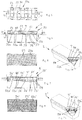
- FIG. 3 shows a vacuum box 2 in more detail.
- the vacuum box 2 comprises a bottom 36, two opposite long sides 37, 38, two opposite short sides 39, 40, or end walls, and a top 41.
- the end walls 39, 40 are inclined so that the vacuum box 2 tapers in a direction towards its bottom 36.
- Such a tapering design is advantageous for the turning of the vacuum box 2 at the bends of the endless belt 1, i.e. over the turn pulley 4a of the drive means 4, and at the suction station 5, and at the backwash station 14.
- the tapering design provides an easy solution for enables to arrange adjacent vacuum boxes 2 and especially the filters 7 thereof close to one another at the straight portion of the belt 1 between the suction station 5 and the drive means 4 which is at the discharge station 10.
- the vacuum box 2 comprises an inside space 3 for receiving filtrate originating from the slurry.
- the residue (the filter cake) will collect on the upper surface of the vacuum boxes 2, on the capillary filter 7 thereof.
- the capillary filter media will prevent air from entering the inside space 3 of the vacuum boxes 2.
- the stiff nature of the filter media will support the filter cake and makes it possible to form a cake of a very even thickness onto the filter medium.
- the capillary filter 7 is preferably a micro porous ceramic filter preferably in the form of a stiff plate.
- a ceramic filter is stiff and has a good endurance against corrosion; it is also durable and strong.
- the filter can be a micro porous metallic or plastic filter [or other material providing capillary action and resistance against corrosion which are required in the belt filter].
- the filter need not, however, be stiff; it can be alternatively a flexible cloth, fabric or film supported from below. If the filter is flexible (a flexible cloth), it must be supported from above if backwash of the filter is carried out.
- a supported flexible filter material can be designed in a filter cartridge, which can be attached onto a frame to form a vacuum box.
- the effective filtering area of the capillary filter 7 is preferably 1 to 5 m 2 , e.g. 1 m 2 , and the volume of the vacuum box 2 is 10 l to 500 l, preferably 50 l to 200 l.
- the dimensions and volume of the vacuum box 2 can vary depending on application.
- the pore size of the filter 7 is 0.03 ⁇ m to 5 ⁇ m, preferably 0.04 ⁇ m to 3 ⁇ m, and even more preferably 0.05 ⁇ m to 2 ⁇ m calculated from the bubble point of the material for pure water.
- the bubble point refers to an effective bubble point.
- the effective bubble point describes a pressure difference between the upper surface of the capillary filter 7 (c.f. the top 41 of the vacuum box 2) and the inside surface of the capillary filter (i.e. the clean side of the capillary filter facing the inside space 3 of the vacuum box 2) at which 1 liter of air flows through one square meter of the filter surfaces during a one minute time.
- the (effective) bubble point of the capillary filter 7 is 0.9, when a 0.9 bar pressure difference is provided in such a capillary filter 7 between the outside surface of the filter and the inside surface of the capillary filter, 1 liter of air passes through a square meter of the filter surfaces during one minute. If the bubble point is 0.9 bar and the total area of the filter surfaces is 2 square meters, 2 I of water passes through the filter surfaces in one minute..
- the bubble- point of the capillary filter 7 is in the range of 0.5 bar to 1.5 bar, and preferably 0.8 bar to 1 bar. If filtering is carried out with a pressure difference which is below the bubble point, air does not penetrate the filter cake or the filter, and there is no pressure loss owing to air flow.
- the vacuum box does not function well unless the material to be filtered is highly compressible, such as organic mass (e.g. chemical pulp). If the bubble point is above 1 bar, e.g. 1.5 bar or even 3 bar, the filtering works, but the pore size is small and the flow resistance is big if the thickness of the filter material is not adjusted to be proportionally smaller.
- the capillary filter 7 is part of a replaceable filter element 50, which is described in more detail with reference to Figure 4a and Figures 4 to 6.
- Figures 4a and 4 show a vacuum box 2 with the filter element 50.
- the replaceable filter element 50 is a spare part of the vacuum belt filter.
- the replaceable filter element 50 shown in Figures 4a, 4 and 5 comprises a preferably planar capillary filter 7 comprising a first permeable filter surface 51 for receiving a feed, a second surface 53 of the capillary filter being opposite to the first filter surface, and a support structure 52 for supporting the second surface of the capillary filter.
- the capillary filter 7 is preferably rectangular.
- the width of the capillary filter 7 is 0.1 m to 0.3 m; and the length of the capillary filter is 1.5 m to 3 m, the length being 5 to 10 times the width of the capillary filter. Said length dimension is transverse to the direction to the direction of motion of the belt 1.
- the thickness of the capillary filter 7 is preferably 0.1 mm to 10 mm. If the support structure is of plastic material, the thickness of the capillary filter 7 is preferably 0.2 mm to 10 mm.
- the support structure 52 is designed to provide an even support for the capillary filter 7. Without a support structure 52 the risk of break of the capillary filter 7 is big, especially if the capillary filter is made of ceramic material.
- the support structure 52 is preferably via an intermediate layer 60 permanently attached to the second surface 53 of the capillary filter 7 and it is designed to support the capillary filter in such a way that the capillary filter does not break in use, i.e. when a pressure difference acts over the first filter surface 51 and the second surface 53 causing huge forces on the capillary filter 7.
- the intermediate layer 60 is highly preferred, because it makes it easy to attach the support structure 52 to the capillary filter 7.
- a first surface of the intermediate layer 60 faces the second surface 53 of the capillary filter 7, and a second surface of the intermediate layer being opposite to the first surface faces the support structure 52.
- the intermediate layer 60 is preferably ceramic.
- the support 52 structure for the capillary filter 7 is preferably in the form of a planar support element also called a first support element 52a in the following.
- the support structure 52 defines a cavity 56, a plurality of support parts 54 for supporting the second surface of the capillary filter being arranged in the cavity.
- the support parts 54 may preferably be shaped as studs.
- the number of support parts 54 is 50 to 4000 per square meter. If the support parts 54 have a round cross section (in a plane parallel to the plane of the planar support structure 52), the number of support parts is preferably 1000 to 4000 per square meter, more preferably 1500 to 2500 per square meter.
- the number of support parts is preferably 50 to 400 per square meter, more preferably 100 to 200 per square meter.
- the support parts 54 are spaced from one another in order to provide an even support for the capillary ceramic filter 7.
- Preferably the support parts 54 are evenly distributed below the second surface 53 of the capillary ceramic filter 7.
- the support structure 52 may be designed to prevent transfer of forces between the support parts 54.
- the support structure 52 comprises connectors 55 for connecting each support part 54 to at least one other support part, c.f. Figure 5 .
- the support structure 52 preferably forms a grid structure as one can see from Figure 5 .
- the thickness of the support structure 52 depends on many parameters, such as the surface area of the capillary filter 7. A suitable thickness is believed to be 50 mm to 200 mm.
- the support parts 54 facing the second surface 53 of the capillary filter 7 form a plurality of support surfaces against the second surface of the intermediate layer 60 and indirectly against the capillary filter 7, which support surfaces amount to 5 per cent to 60 per cent, preferably 10 per cent to 40 per cent, and more preferably 15 per cent to 25 per cent of a total area of the second surface of the capillary filter.
- the intermediate layer 60 is preferably a ceramic layer.
- the second surface of the intermediate layer 60 comprises a rough joining interface for fastening the support structure 52 permanently to the intermediate layer 60.
- the rough joining interface has a grit number of 40 to 300, preferably 40 to 180, and more preferably 60 to 120.
- Such a grit range functions especially well for fastening support parts 54 made of e.g. thermoplastic material permanently to the second surface of the intermediate layer 60 by e.g. gluing, or by melting the ends of the support parts 54 into the second surface.
- the ends of the support parts 54 are melted into the second surface of the intermediate layer 60, there is a layer comprising the material or the support structure which attaches the support structure to the rough joining interface of the intermediate layer 60.
- the support structure 32 is formed as a unit with the capillary filter 7 and one may say that the support structure is an integral part of the intermediate layer 60 and the capillary filter 7.
- the rough joining interface is formed directly, i.e. without an intermediate layer 60, to the second surface 53 of the capillary filter 7.
- the whole second surface of the intermediate layer 60 need not be roughened; it is sufficient if the second surface is, or has been roughened at points where the support parts 54 are fastened. These points form a rough joining interface.
- the thickness of the intermediate layer 60 is preferably 5 mm to 40 mm, more preferably 5 mm to 20 mm.
- connection between a support parts 54 and the second surface 53 must be sufficient for the filter element 50 to endure pressures acting on the filter element 50 especially during back washing (when the vacuum boxes are cleaned) but also during filtration.
- the connection must be strong enough to endure a pressure difference of at least 0.4 bar, preferably at least 0.7 bar.
- the pressure difference is 0.4 bar; and if the pressure outside the vacuum box 2 is 1 bar and the pressure inside the vacuum box is 1.7 bar, the pressure difference is 0.7 bar.
- the support structure 52 must be strong enough to endure a pressure difference of at least 0.4 bar, preferably at least 0.5 bar, and more preferably at least 0.6 bar over the filter element 7.
- a pressure difference of at least 0.4 bar, preferably at least 0.5 bar, and more preferably at least 0.6 bar over the filter element 7.
- Reference numeral 52b in Figures 4a, 4 and 6 is drawn to a second support element which is fixed to the body part 58 of the vacuum box 2.
- the support element 52b is preferably a planar element which is attached preferably on top of the body part 58 of the vacuum box 2.
- the support element 52b can be an integral part of the body part 58.
- the support element 52b is not part of the filter element 50 (i.e. is not part of the spare part).
- the periphery of the support element 52b can be arranged to be supported on brackets provided inside the body part 58.
- the support element 52b can be attached to the body part 58 of the vacuum box e.g. by clips (not shown) or other fastening means.
- the support element 52b is alternatively or additionally attached to the bottom of the body part 58, e.g. by bolts or other detachable fastening means. Fastening of the support element 52b to the body part 58 is not disclosed here in more detail, because a person skilled in the art readily can find out various suitable designs for such attachment.
- the support element 52b comprises a multitude of holes 57 which enable filtrate to pass into the inside space of the vacuum box 2.
- Figures 7a, 7 and 8 illustrate a second embodiment of the filter element.
- the filter element 50' of Figures 7a, 7 and 8 differs from the embodiment shown in Figure 4a and Figures 4 - 6 in that the support element 52a' is fastened not only to the intermediate layer 60, but also to the support element 52b', which thus is part of the support structure 52' and part of filter element 50'.
- Connectors, c.f. connectors 55 like those in Figure 5 are not needed, because support element 52b' connects the support parts 54'. Support element 52b' is thus also a connecting means.
- the fastening of the support element 52a' to the support element 52b' can be carried out by various manners (permanently e.g. by gluing, or detachably e.g. by snap fasteners) as appreciated by a person skilled in the art.
- the support element 52b' of Figure 8 comprises a multitude of holes 57', like support element 52b of Figure 6 .
- the support element 52b' provides additional stiffness to the support structure 52' and the filter 7' which is advantageous especially during back washing of the filter. Added stiffness is advantageous and important, because it reduces risk of the capillary filter 7' to break during back washing.
- the filter element 50' of Figures 7a, 7 and 8 is also advantageous in that it is a compact structure which can be factory built and easily mounted on site.
- the periphery of filter element 50' is arranged to be supported on brackets 59' provided inside the body part 58 of a vacuum box.
- FIGS 9 and 10 show a third embodiment of the filter element 50".
- a corner area of the filter element 50" is shown opened in the figures - only to illustrate the construction of the filter element.
- the capillary filter 7" is supported by a support structure 52" in the form of a honeycomb structure.
- the honeycomb structure comprises a multitude of spaced holes 58" defined by walls 61".
- the honeycomb structure can preferably be made of plastic, preferably thermoplastic. If the honeycomb structure is made of plastic, there is preferably an intermediate ceramic layer 60" between the filter 7" and the honeycomb structure as shown in Figures 9 and 10 .
- the intermediate ceramic layer 60" has a grit number of 40 to 300, preferably 40 to 180, more preferably 60 - 120 which grid values form a rough joining interface for attaching of the honeycomb structure to the capillary filter 7".
- the honeycomb structure can alternatively be made of e.g. ceramic material. If the support structure 52" is made of ceramic material and the capillary filter 7" is of ceramic material, no intermediate layer 60" is needed.
- the thickness of the honeycomb structure is 5 mm to 200 mm, preferably 10 mm to 150 mm.
- FIGS 11 and 12 show a fourth embodiment of the filter element.
- the filter element 50'" of Figures 11 and 12 differs from the filter element 50'" of Figures 9 and 10 essentially in that the support structure 52" is a compact piece of porous material, i.e. it does not comprise (macroscopic) holes, c.f. holes 58" in Figure 10 ..
- a corner of the filter element 50'" is shown opened to illustrate this.
- the pore size of the compact piece is bigger than the pore size of the ceramic filter 7"'.
- the piece is preferably a ceramic brick preferably made of a highly porous material. Alternatively, a compact piece of plastic or a piece of porous metal can be used.
- the capillary filter 7'" has been formed onto the brick preferably by spraying.
- the manufacturing of the filter element 50'" comprises preferably compressing a raw material to a brick, burning the brick in an oven, spraying the brick with a ceramic membrane layer, and finally burning the brick with the membrane layer in an oven.
- the brick has a grit number of 40 to 300, preferably 40 to 180, more preferably 60 to 120. If the brick is manufactured of a material having an average grit number e.g. 100, one hundred particles arranged in a row fill up a distance of one inch. Alternatively, the brick could be glued to the capillary filter 7"'. If glued, the filter surface facing the brick should be rough, preferably having a grit number of 40 to 180, and more preferably 60 to 120, in order to achieve a strong bond.
- the thickness of the brick is preferably 10 mm to 100 mm.
- the thickness of the capillary filter 7'" is preferably 0.1 mm to 10 mm, preferably 0.1 mm to 7 mm.
- the vacuum boxes and the filters 7 thereof can easily be individually replaced in contrast to a conventional vacuum belt filter employing a filter cloth as filtering media.
- a whole worn filter cloth worn e.g. owing to stretching
- the length of which typically is dozens of meters the replacement being cumbersome and time consuming.
- the outlet 8 of the vacuum box 2 has a check valve 9 which enables fluid to be withdrawn from the inside space 3 of the vacuum box out from the vacuum box via the outlet.
- the check valve 9 is illustrated in Figure 14 in more detail.
- the check valve 9 comprises a spring 46 which urges a blocking member 9a of the check valve 9 against a seat.
- the spring 46 is a helical spring, but other types of springs can be employed. When the spring 46 is in its maximally extended position, the check valve 9 is closed, and no fluid (liquid, gas or other substance) may enter from the inside space 3 of the vacuum box 2 to the outside of the vacuum box through the outlet 8. When the pressure from the inside space 3 of the vacuum box 2 exceeds the pressure created by the spring 46 against the blocking member 9a, the check valve 9 is open.
- a rubber spring can be used; or cup springs.
- a gas spring instead of a spring loaded check valve having a separate spring which activates the movement of a blocking member, other types of check valves can be used.
- the check valve can function based on the design of e.g. a membrane, clack, a poppet, a goose neck, whereby the valve itself functions like a spring.
- the check valve 9 comprises a mechanical actuator for closing a blocking member.
- the check valve can e.g. be a solenoid valve (which may be energized from outside), a mechanically controlled valve, a pneumatically controlled valve and/or a hydraulically controlled valve.
- the spring 46 or other mechanical actuator is not indispensable, because the blocking member 9a can owing to underpressure within the inside space 3 of the vacuum box 2 be kept in a blocking position.
- the basic structure of the check valve may be based on e.g. a membrane, a clack, a poppet, a goose neck, a ball, a slide, a flex hose, a needle or any other type of valve known per se.
- Reference numeral 13 indicates an inlet of the vacuum box 2.
- Figure 13 shows a spring loaded check valve 15 in the inlet 13.
- a spring 16 of the check valve 15 urges a blocking member 15a of the check valve 15 against a seat.
- the spring 16 is a helical spring, but other types of springs can be employed as explained above for spring 46.
- the check valve 15 When the spring 16 is in its extended position, the check valve 15 is closed, and no fluid (liquid, gas or other substance) may enter to the inside space 3 of the vacuum box 2.
- the blocking member 15a By applying on the blocking member 15a an external force which is opposite to the force of the spring 16, the blocking member 15a can be displaced in a direction towards the spring 16 (i.e. upwards in Figure 13 ), whereby the spring flexes and the check valve 15 opens.
- check valve 15 In order that the check valve 15 opens, the pressure acting from the outside of the vacuum box 2 on the blocking member 15a must be bigger than the force of the spring and the pressure acting from the inside of the vacuum box on the blocking member.
- check valve 9 instead of a spring loaded check valve 15 having a separate spring which activates the movement of a closing member, other types of check valves can be used. More generally defined, the check valve 15 comprises a mechanical actuator for closing a blocking member.
- the inside space (see reference numeral 3 in Figure 3 ) of the vacuum boxes 2 have the same pressure as the surrounding atmosphere, i.e. 1 atmosphere (1 bar). However, the inside space can have a pressure deviating from the pressure of the surrounding atmosphere.
- vacuum box 2a illustrates a vacuum box entering the suction station 5.
- the inlet 13 of the vacuum box 2a will not open but is kept closed owing to the spring 16 of the spring loaded check valve 15, c.f. Figures 3 and 13 .
- the spring force of the spring 16 must be bigger than the force of the suction in order to keep the inlet 13 closed during suction and in order to create and maintain an underpressure within the vacuum box 2a.
- An absolute pressure of 0.05 bar to 0.5 bar, preferably 0.05 bar to 0.15 bar is created within the vacuum box 2.
- check valves 9, 15 When check valves 9, 15 are closed, no fluid (liquid, gas or other substance) can enter the inside 3 of the vacuum box 2 through the check valves 9, 15.
- Check valve 9 is closed when the pressure at the outlet of the check valve 9 is higher than the pressure at the inside space 3 of the vacuum box 2 the spring 46 providing an additional force to displace the blocking member 9a into the closed position (shown in Figure 14 ).
- Spring 16 keeps check valve 15 closed when there is an underpressure within the vacuum box 2.
- the check valves 9, 15 enable to maintain an underpressure inside the vacuum box 2 when it travels from the suction station 5 to the discharge station 10.
- the vacuum box 2 can be called a vacuum accumulator. Owing to the underpressure within the vacuum box 2, a slurry will continuously be filtered when the vacuum box moves between the feed station 29 and the discharge station 10, i.e. without any fluid communication between the inside space 3 of the vacuum box 2 and the suction station 5.
- a filtrate i.e. water or other liquid
- water from the slurry is transported into the vacuum box 2 through the capillary action of the filter 7.
- a residue is collected and built up on the upper side of the vacuum box 2 on the upper side of the filter 7.
- filtrate water
- the volume of gas in the inside space 3 of the vacuum box will gradually decrease and consequently the absolute pressure within the vacuum box will increase. If, for example, the initial absolute pressure within the vacuum box 2 is 0.05 bar at the suction station 5, and the gas volume is reduced by for example 20% during filtration, the absolute pressure in the vacuum box 2 will increase to 0.25 bar.
- a dewatering station 47a is positioned between the suction station 5 and the discharge station 10.
- the construction of the dewatering station 47a is similar to the concentration of the suction station 5.
- the dewatering station 47a has in Figure 1 been drawn as a box.
- filtrate can be removed from the inside space 3 of the vacuum box 2 by opening the check valve 15 and/or the check valve 9.
- Outlet 8 and the check valve 9 therein are the primary components for removal of filtrate.
- the additional suction station 5b is of the same type as the suction station 5, i.e. it has a stationary distribution part (not shown), conduits, suction ends etc., like the suction station 5.
- the additional suction station 5b typically can be used for removing filtrate from the vacuum boxes 2, it can be called a dewatering station.
- the location of the additional suction station 5b can be chosen relatively freely between the discharge station 10 and the feed station 29.
- the additional suction station 5b is not indispensable, but it makes the liquid-solid separation of slurry much faster.
- Reference numeral 47b shows an additional dewatering station positioned between the additional suction station 5b and the discharge station 10.
- the construction of the additional dewatering station 47b is similar to the construction of the dewatering station 47a.
- the number of dewatering stations can vary; typically there is zero to three dewatering stations, preferably one to three dewatering stations in the vacuum belt filter.
- the upper region of the belt 1 is inclined downward by preferably 1 degree to 10 degrees with respect to the horizontal downstream the suction station 5.
- the belt is inclined up to the location of the discharge station 10. Thanks to the inclination, slurry is not drift - at least to a higher extent - on the vacuum boxes 2 in a direction opposite to the travel direction of the belt 1. This prevents slurry from entering backwards to the suction station 5 and falling down downstream the suction station.
- the moisture content of the residue can e.g. be 40% to 50% close to the feed station 5, and when the residue comes to the discharge station 10, the moisture content of the residue is 5 to 25% depending on nature and size of particles, and the residue is in the form of a filter cake.
- a low moisture content is especially of importance for example in filtering organic materials with high specific filtration resistance, such as biomass, organic waste or algae in energy production.
- the thickness of the filter cake can be dozens of millimeters when the vacuum box 2 enters the discharge station 10.
- the weight of the filter cake depends on filtering area, type of slurry etc.; it can e.g. be 5 kg when it enters the discharge station 10.
- the residue is removed by the scrapers 11 and is discharged to the discharge container 31 underneath.
- the upper surface of the filter 7 of the vacuum box 2 is preferably sprayed with wash fluid, typically water.
- Reference numeral 12 shows the spray means for carrying out said cleaning.
- the spray means 12 comprise nozzles for spraying water against the upper surface of the filter 7.
- the spraying pressure can be e.g. 5 bar to 10 bar.
- the water can be at least partly taken from one or more of the following stations: the dewatering station 47a, the additional suction station 5b, the additional dewatering station 47b, and the backwash station 14.
- the vacuum boxes 2 are cleaned in the backwash station 14.
- the construction of the backwash station 14 is similar to the construction of the suction station, i.e. it comprises a non-rotatable stationary distribution part 48 corresponding to the stationary distribution part 32 of the suction station 5, and a rotating member 6 corresponding to the rotating member 25 of the suction station 5; it comprises a rotating distribution valve arrangement 17 having a construction which preferably is similar to the construction of the rotating suction arrangement 24 of the suction station 5.
- the rotating member 6 of the rotating distribution valve arrangement 17 comprises a rotating periphery 21 provided with a plurality of distribution ends 19 arranged along the entire periphery 21 of the rotating member 6, but for sake of simplicity only two distribution ends have been drawn in Figure 1 .
- the distribution ends 19 are arranged at a distance X from each other corresponding to the distance Y between the inlets 13 of adjacent vacuum boxes 2.
- the distribution ends 19 are adapted to be connected to the inlets 13 of the vacuum boxes 2 in order to feed wash fluid to the inside space 3 of the vacuum boxes 2.
- the rotating distribution valve arrangement 17 is provided with a valve system which is (as explained in more detail below) adapted to open fluid communication between a wash fluid source (possibly containing wash fluid from the dewatering station) and the distribution ends 19 only when the distribution ends 19 are connected to the inlets 13 of the vacuum boxes.
- the rotating member 6 of the rotating distribution valve arrangement 17 comprises further an inner rim 18 corresponding to the inner rim 44b of the rotating member 25 of the suction arrangement 5 and conduits (not shown) corresponding to conduits 35 of the rotating suction arrangement 24 of the suction arrangement 5.
- the opening (not shown) of the stationary distribution part 48 has a shape and curvature which corresponds to the shape and curvature of the inner rim 18 to provide effective fluid communication between the stationary distribution part 48 and the channels (not shown) in the rotating member 6.
- the inner rim 18 is preferably circular (like the inner rim 44b of the rotating member 25).
- the inlet 13 of the vacuum box comes into contact with the distribution ends 19 of the backwash station 14.
- the distribution ends 19 are adapted to press the blocking member 15a of the check valve 15 so that the check valve 15 opens for enabling wash water to enter to the inside space 3 of the vacuum box 2. It is conceivable that the distribution ends 19 are adapted not to press the blocking member 15a but to press only against the inlet 13, which is possible if the pressure of the wash fluid is high enough to open the check valve 15 against the spring force of the check valve.
- the outlet 8 shall be closed at least partly so that water does not forcefully flow out from the outlet 8.
- the spring 46 in the outlet 8 partly serves for such closing.
- the spring 46 provides only for a minimal closing effect, because a low opening pressure for check valve 9 is wanted as a near absolute vacuum in to the vacuum box is strived at.
- the outlet 8 of the vacuum box 2 can, however, effectively be closed by a blocking element 20 arranged on a rotating periphery 21 of the rotating distribution valve arrangement 17.
- Said periphery is preferably the same periphery as the one having the distribution ends 19.
- Blocking elements 20 are arranged along the entire periphery 21 of the rotating distribution valve arrangement 17, but for sake of simplicity only two blocking elements have been drawn in Figure 1 .
- the blocking elements 20 are arranged at a distance L from each other corresponding to the distance T between the outlets 8 of adjacent vacuum boxes 2.
- the blocking elements 20 are adapted to engage the outlets 8 and close them forcefully to prevent wash fluid from flowing from the inside space 3 of the vacuum box out from the outlets 8 of the vacuum boxes 2.
- the blocking elements 20 are adopted to close the outlets 8 by closing the check valves 9.
- the check valves 9 can be forcefully closed when the blocking elements 20 are engaged with the check valves 9. If no blocking elements 20 are arranged in the outlets 8, wash fluid can freely flow out from the outlets 8 through the check valves 9.
- the backwash pressure should be higher than the differential pressure used in filtration.
- the cleaning of the vacuum boxes 2 can normally be carried out with an over-pressure of 1 to 2 bar.
- FIG 2 illustrates the above described opening of inlets 13 by the aid of the distribution ends 19 of the distribution valve arrangement 17 and illustrates also the blocking of the outlets 8 with blocking elements 20 at the backwash station 14.
- the vacuum boxes 2 pass a wash vat 22 arranged in connection with the backwash station 14.
- ultrasonic transducers 23 are arranged in the wash vat 22 for applying sound waves to the filters 7 of the vacuum boxes 2.
- the filters 7 of the vacuum boxes 2 are washed (cleaned) with acids. This is possible, because the filters 7 are made from a material which stands acids, e.g. a ceramic material such as Al 2 O 3 , SIC, aluminium silicate, and titania.
- the material of the filter can also be metal or plastic having the required mechanical strength and corrosion resistance.
- the vacuum boxes 2 arrive to the suction station 5 for being connected to the rotating distribution valve suction arrangement 24 of the suction station 5.
- an underpressure is created into the vacuum boxes 2 as described above.
- the vacuum belt filter is covered with a hood (not shown) if poisonous gases are formed in the liquid-solid separation carried out by the vacuum belt filter.
- a major advantage with the belt filter of the present invention is that all capillary filters must not be replaced at the same time; it is expected to be sufficient that only one or a few capillary filters which have worn or broken are replaced.
- a worn or broken capillary filter can easily and fast be replaced by detaching from the belt 1 a respective vacuum box 2 having the worn or broken capillary filter and putting in its place on the belt 1 a new vacuum box having a new capillary filter.
- the worn or broken capillary filter is detached from the vacuum box 2 while keeping the vacuum box attached to on the belt 1, and a new capillary filter is attached to the vacuum box on the belt.
- check valves 9 of the vacuum boxes 2 wear in use or may break, they must at some time be replaced. Not all check valves of the vacuum boxes must not be replaced at the same time; only a check valve which is replaced.
- a worn or broken check valve 9 can be replaced by detaching from the belt 1 a respective vacuum box 2 having the worn or broken check valve and putting in its place on the belt 1 a new vacuum box having a new check valve.
- a worn or broken check valve 9 is detached from the vacuum box 2 while keeping the vacuum box attached to on the belt 1, and a new check valve is mounted to the vacuum box on the belt.
- the method for carrying out liquid-solid separation of the slurry in the vacuum belt filter according to the invention comprises the essential method steps as follows:
- the belt 1 with its vacuum boxes 2 travel in one and the same direction of travel in a circular motion the vacuum boxes thus forming an endless belt and a closed loop, whereby the separation process preferably is continuous.
- the suction station 5 is positioned downstream the discharge station 10 (seen in the direction of the moving belt 1).
- the belt 1 (with its vacuum boxes 2) can be moved intermittently back and forth.
- moving the belt 1 intermittently is considered not to be very effective in comparison with a continuous process where the belt moves continuously in one and the same direction; an intermittent process requires also a modification fo the lay out of the components of the vacuum belt filter shown in the drawings.
- the method for carrying out liquid-solid separation of the slurry in the vacuum belt filter comprises additionally the steps of backwashing the boxes and preferably also spraying cleaning fluid, typically water, on the upper surface of the capillary filters 7.
- cleaning fluid typically water
- each vacuum box has no inlet which is separate from the outlet.
- the suction station does is not necessarily of the type comprising a rotating member having a plurality of suction ends, although this is highly preferable.
- the distribution surface (44) of the suction station (5) need not to be formed on an inner rim (44b) of the rotating member (25) of the rotating suction arrangement (24), but can e.g. be an end surface which is perpendicular to the central axis of the rotating member (25).
- the number of conduits (35) in the rotating member (25) can vary.
- Spray means (12) between the discharge station (10) and the backwash station (14) are optional.
- the vacuum belt filter need not necessarily have a backwash station (14) although it is highly recommendable.
- a backwash station (14) is present, the components of the backwash station can vary; e.g. transducers are not necessary for cleaning the filters and vacuum boxes; it is conceivable to clean the filters with an acid.
- the number of vacuum boxes and the length of the belt can largely vary depending on application.
- An endless belt (1) is the most practical solution as all unit processes involved in the filtration cycle can be stationary organized.
- the belt (1) need not be an endless belt although an endless belt is highly recommendable; thus, the belt can be a belt arranged to move intermittently back and forth, whereby the vacuum boxes move intermittently between the suction station (5) and the discharge station (10).
- a reciprocating process is a complicated solution and it may typically also not be continuous, which may weaken the efficiency of the liquid-solid separation process.
- the number of backwash stations (14) can vary.
- One or more filter cake washing apparatuses (49) positioned upstream the discharge station (10) can be included in the vacuum belt filter.
- the vacuum belt filter comprises a cake washing apparatus and an additional suction station (5b)
- the latter should be positioned downstream the cake washing apparatus so that water sprayed on the filter cake has time to be absorbed into the filter cake and through the filter cake to the inside space (3) of the vacuum box (2); and the water can subsequently be removed from the inside space (3) through the outlet (8) of the vacuum box (2).
Claims (19)
- Vakuumkasten (2) für einen Vakuumbandfilter, wobei der Vakuumkasten einen Innenraum (3) zur Aufnahme eines Filtrats umfasst, wobei der Vakuumkasten (2) umfasst:einen Kapillarfilter (7), wobei der Blasenbildungspunkt des Kapillarfilters im Bereich von 0,5 bar bis 1,5 bar liegt, undeinen Boden (36), zwei gegenüberliegende lange Seiten (37, 38), zwei gegenüberliegende kurze Seiten (39, 40) und ein Oberteil (41) sowie einen Innenraum (3) zur Aufnahme von Filtrat, das aus einer Suspension stammt;wobei der Vakuumkasten (2) mit einem Auslass (8) versehen ist, der ein Rückschlagventil (9) aufweist, das einen Flüssigkeitsstrom aus dem Innenraum (3) des Vakuumkastens (2) zur Außenseite des Vakuumkastens (2) ermöglicht, um einen Unterdruck im Vakuumkasten (2) zu erzeugen, der Vakuumkasten in der Lage ist, den Unterdruck in seinem Innenraum (3) aufrecht zu erhalten, ohne an eine Vakuumquelle angeschlossen zu sein, und wobei das Rückschlagventil (9) einen Flüssigkeitsstrom zum Innenraum (3) des Vakuumkastens verhindert.
- Vakuumkasten (2) nach Anspruch 1, gekennzeichnet dadurch, dass das Rückschlagventil (9) des Auslasses (8) einen mechanischen Aktor zum Schließen eines Sperrglieds (9a) des Rückschlagventils umfasst.
- Vakuumkasten (2) nach Anspruch 1 oder 2, gekennzeichnet dadurch, dass die Porengröße des Kapillarfilters 0,03 µm bis 5 µm beträgt.
- Vakuumkasten (2) nach einem vorhergehenden Anspruch 1 bis 3, gekennzeichnet dadurch, dass der Kapillarfilter (7) ein Keramikfilter ist.
- Vakuumkasten (2) nach einem vorhergehenden Anspruch 1 bis 4, gekennzeichnet dadurch, dass er mit einem Einlass (13) zum Eintragen von Waschflüssigkeit in den Innenraum (3) des Vakuumkastens und auf der Reinseite des Kapillarfilters (7) versehen ist.
- Vakuumkasten (2) nach Anspruch 5, gekennzeichnet dadurch, dass der Einlass (13) ein Rückschlagventil (15) umfasst, das einen mechanischen Aktor zum Schließen eines Sperrglieds (15a) des Rückschlagventils umfasst, wobei der mechanische Aktor das Sperrglied (15a) des Rückschlagventils (15) und das Rückschlagventil (15) in einer geschlossenen Stellung hält, wenn ein Druck, der von der Außenseite des Vakuumkastens (2) gegen das Sperrglied (15a) und gegen eine Kraft des mechanischen Aktors wirkt, kleiner ist als die Summe der Kraft des mechanischen Aktors und des von der Innenseite (3) des Vakuumkastens (2) auf das Sperrglied (15a) wirkenden Drucks; und das Rückschlagventil (15) öffnet, wenn der Druck, der von der Außenseite des Vakuumkastens (2) gegen das Sperrglied (15a) und gegen den mechanischen Aktor wirkt, größer ist als die Summe der Kraft des mechanischen Aktors und des von der Innenseite (3) des Vakuumkastens (2) auf das Sperrglied (15a) wirkenden Drucks.
- Vakuumbandfilter, der ein Band (1) mit einer Mehrzahl von nacheinander angeordneten Vakuumkästen (2) umfasst, wobei Filtermittel an den Vakuumkästen angeordnet sind, wobei jeder Vakuumkasten einen Boden (36), zwei gegenüberliegende lange Seiten (37, 38), zwei gegenüberliegende kurze Seiten (39, 40) und ein Oberteil (41) umfasst und einen Innenraum (3) zur Aufnahme eines Filtrats definiert, wobei der Vakuumbandfilter ferner umfasst:
Antriebsmittel (4) zum Bewegen des Bands (1) und eine Saugstation (5), die Saugmittel umfasst, die an Auslässe (8) der Vakuumkästen (2) angeschlossen werden können, um im Verhältnis zu einem Umgebungsdruck an die Vakuumkästen einen Unterdruck an der Saugstation (5) anzulegen, wobei die Vakuumkästen jeweils einen Kapillarfilter (7) umfassen, wobei der Blasenbildungspunkt des Kapillarfilters im Bereich von 0,5 bar bis 1,5 bar liegt, der Auslass (8) jedes Vakuumkastens mit einem Rückschlagventil (9) versehen ist, das einen Flüssigkeitsstrom aus dem Innenraum (3) des Vakuumkastens zur Außenseite des Vakuumkastens ermöglicht, um einen Unterdruck im Vakuumkasten zu erzeugen und aufrecht zu erhalten, wenn die Saugstation (5) am Auslass (8) des Vakuumkastens angeschlossen ist, wobei das Rückschlagventil (9) einen Flüssigkeitsstrom durch das Rückschlagventil zum Innenraum (3) des Vakuumkastens verhindert, wenn der Vakuumkasten die Saugstation (5) verlässt, und dadurch den Vakuumkasten in einem Unterdruck im Verhältnis zum Umgebungsdruck hält, wenn der Vakuumkasten aus dem Einfluss der Saugstation gerät. - Vakuumbandfilter nach Anspruch 7, gekennzeichnet dadurch, dass die Saugstation (5) ein nicht drehbares stationäres Verteilungsteil (32) umfasst und dass das Saugmittel eine drehende Verteilungsventil-Sauganordnung (24) umfasst, wobei das stationäre Verteilungsteil (32) einen Sauganschluss (34) mit einer Saugöffnung (34a) umfasst und die drehende Verteilungsventil-Sauganordnung (24) ein Drehglied (25) umfasst, das eine Mehrzahl von an die Auslässe (8) der Vakuumkästen (2) anschließbaren Saug-Enden (26) aufweist, wobei die Saug-Enden (26) am Drehglied (25) peripher (25a) angeordnet sind, mehrere benachbarte Öffnungen (44a) an einer Verteilungsoberfläche (44) des Drehglieds (25) vorgesehen sind, die Öffnungen (44a) in einem Abstand (U) zueinander angeordnet sind und das Drehglied (25) ferner eine Mehrzahl von Kanälen (35) umfasst, die jeweils ein erstes Ende (35a), das mit einem Saug-Ende (26) der mehreren Saug-Enden des Drehglieds strömungstechnisch verbunden ist, und ein zweites Ende (35b), das mit einer Öffnung (44a) der mehreren Öffnungen des Drehglieds (25) strömungstechnisch verbunden ist, aufweisen, wobei die Saugöffnung (34a) des stationären Verteilungsteils (32) nur einer oder einigen der Öffnungen (44a) der Verteilungsoberfläche (44) zugewandt ist, so dass die eine oder die einigen der Öffnungen der Verteilungsoberfläche (44) in Intervallen in eine strömungstechnische Verbindung mit der Saugöffnung (34a) treten, wenn sich das Drehglied (25) und dessen Verteilungsoberfläche (44) im Verhältnis zum stationären Verteilungsteil (32) drehen.
- Vakuumbandfilter nach Anspruch 8, gekennzeichnet dadurch, dass die Verteilungsoberfläche (44) aus einem Innenrand (44b) des Drehglieds (25) ausgebildet ist.
- Vakuumbandfilter nach Anspruch 8 oder 9, gekennzeichnet dadurch, dass er eine der Saugstation (5) nachgeschaltete Austragsstation (10) umfasst, wobei die Austragsstation Schaber (11) zum Entfernen von Rückständen aus den Kapillarfiltern (7) umfasst.
- Vakuumbandfilter nach Anspruch 10, gekennzeichnet dadurch, dass er eine Rückspülstation (14) zum Eintragen von Waschflüssigkeit in den Innenraum (3) der Vakuumkästen (2) umfasst, wobei die Vakuumkästen (2) jeweils einen Einlass (13) umfassen, um die Waschflüssigkeit aus der Rückspülstation (14) aufzunehmen und die Waschflüssigkeit in den Innenraum (3) des Vakuumkastens und auf der Reinseite des Kapillarfilters (7) einzutragen.
- Vakuumbandfilter nach Anspruch 11, gekennzeichnet dadurch, dass die Rückspülstation (14) umfasst: eine drehende Verteilerventilanordnung (17) mit einem Drehglied (6), das eine drehenden Peripherie (21) aufweist, die mit einer Mehrzahl von Verteiler-Enden (19) versehen ist, um Rückwaschflüssigkeit in den Innenraum (3) der Vakuumkästen (2) und auf der Reinseite des Kapillarfilters (7) der Vakuumkästen einzutragen, wobei die Verteiler-Enden (19) in einem Abstand (X) zueinander angeordnet sind, der dem Abstand (Y) zwischen den Einlässen (13) benachbarter Vakuumkästen (2) entspricht, wobei die Verteiler-Enden (19) so eingerichtet sind, dass sie mit den Einlässen (13) der Vakuumkästen (2) verbunden werden, um Waschflüssigkeit in den Innenraum (3) der Vakuumkästen (2) einzutragen.
- Vakuumbandfilter nach Anspruch 12, gekennzeichnet dadurch, dass die drehende Verteilerventilanordnung (17) Sperrelemente (20) umfasst, die an der drehenden Peripherie (21) der drehenden Verteilerventilanordnung angeordnet sind, wobei die Sperrelemente (20) in einem Abstand (L) zueinander angeordnet sind, der dem Abstand (T) zwischen den Auslässen (8) benachbarter Vakuumkästen (2) entspricht, wobei die Sperrelemente (20) so eingerichtet sind, dass sie die Rückschlagventile (9) schließen, um zu verhindern, dass Flüssigkeit aus den Auslässen (8) der Vakuumkästen ausströmt, wenn die Sperrelemente (20) mit den Rückschlagventilen (9) im Eingriff stehen.
- Vakuumbandfilter nach einem vorhergehenden Anspruch 11 bis 13, gekennzeichnet dadurch, dass er umfasst: eine Entwässerungsstation (47a) zum Leeren der Vakuumkästen (2) von Filtrat und Kanäle zum Führen des Filtrats von der Entwässerungsstation zur Rückspülstation (14) oder zu Sprühmitteln (12), die zwischen der Austragsstation (10) und der Rückspülstation (14) angeordnet sind, um Filtrat gegen eine Oberseite der Vakuumkästen (2) des Bands (1) zu sprühen.
- Vakuumbandfilter nach einem vorhergehenden Anspruch 7 bis 14, gekennzeichnet dadurch, dass das Band (1) des Vakuumbandfilters ein Endlosband ist.
- Vakuumbandfilter nach einem vorhergehenden Anspruch 8 bis 15, gekennzeichnet dadurch, dass die Vakuumkästen (2) so angeordnet sind, dass sie sich zwischen der Saugstation (5) und der Austragsstation (10) hin und her bewegen.
- Verfahren zur Wartung eines Vakuumbandfilters, der ein Band (1) mit einer Mehrzahl von nacheinander angeordneten Vakuumkästen (2) umfasst, wobei Filtermittel an den Vakuumkästen angeordnet sind, wobei jeder Vakuumkasten einen Boden (36), zwei gegenüberliegende lange Seiten (37, 38), zwei gegenüberliegende kurze Seiten (39, 40) und ein Oberteil (41) umfasst und einen Innenraum (3) zur Aufnahme eines Filtrats definiert, wobei der Vakuumbandfilter ferner umfasst: Antriebsmittel (4) zum Bewegen des Bands (1) und eine Saugstation (5), die Saugmittel umfasst, die an Auslässe (8) der Vakuumkästen (2) angeschlossen werden können, um im Verhältnis zu einem Umgebungsdruck an die Vakuumkästen einen Unterdruck an der Saugstation (5) anzulegen, wobei die Vakuumkästen jeweils einen Kapillarfilter (7) umfassen, wobei der Blasenbildungspunkt des Kapillarfilters im Bereich von 0,5 bar bis 1,5 bar liegt, der Auslass (8) jedes Vakuumkastens mit einem Rückschlagventil (9) versehen ist, das einen Flüssigkeitsstrom aus dem Innenraum (3) des Vakuumkastens zur Außenseite des Vakuumkastens ermöglicht, um einen Unterdruck im Vakuumkasten zu erzeugen und aufrecht zu erhalten, wenn die Saugstation (5) am Auslass (8) des Vakuumkastens angeschlossen ist, wobei das Rückschlagventil (9) einen Flüssigkeitsstrom durch das Rückschlagventil zum Innenraum (3) des Vakuumkastens verhindert, wenn der Vakuumkasten die Saugstation (5) verlässt, und dadurch den Vakuumkasten in einem Unterdruck im Verhältnis zum Umgebungsdruck hält, wenn der Vakuumkasten aus dem Einfluss der Saugstation gerät, wobei der Schritt der Wartung umfasst:- Ausbauen eines zu ersetzenden verschlissenen oder defekten Kapillarfilters (7) aus dem Band (1) und dessen Ersetzen mit einem neuen Kapillarfilter.
- Verfahren nach Anspruch 17, gekennzeichnet durch Ausbauen des verschlissenen oder defekten Kapillarfilters (7) aus einem Vakuumkasten (2) und Anbauen des neuen Kapillarfilters an den Vakuumkasten (2).
- Verfahren zur Durchführung einer Flüssig-Fest-Separation einer Suspension oder dergleichen in einem Vakuumbandfilter, der ein Band (1) mit einer Mehrzahl von nacheinander angeordneten Vakuumkästen (2) umfasst, wobei Filtermittel an den Vakuumkästen angeordnet sind, wobei jeder Vakuumkasten einen Boden (36), zwei gegenüberliegende lange Seiten (37, 38), zwei gegenüberliegende kurze Seiten (39, 40) und ein Oberteil (41) umfasst und einen Innenraum (3) zur Aufnahme eines Filtrats definiert, wobei der Vakuumbandfilter ferner umfasst: Antriebsmittel (4) zum Bewegen des Bands (1) und eine Saugstation (5), die Saugmittel umfasst, die an Auslässe (8) der Vakuumkästen (2) angeschlossen werden können, um im Verhältnis zu einem Umgebungsdruck an die Vakuumkästen einen Unterdruck an der Saugstation (5) anzulegen, wobei die Vakuumkästen jeweils einen Kapillarfilter (7) umfassen, wobei der Blasenbildungspunkt des Kapillarfilters im Bereich von 0,5 bar bis 1,5 bar liegt, der Auslass (8) jedes Vakuumkastens mit einem Rückschlagventil (9) versehen ist, das einen Flüssigkeitsstrom aus dem Innenraum (3) des Vakuumkastens zur Außenseite des Vakuumkastens ermöglicht, um einen Unterdruck im Vakuumkasten zu erzeugen und aufrecht zu erhalten, wenn die Saugstation (5) am Auslass (8) des Vakuumkastens angeschlossen ist, wobei das Rückschlagventil (9) einen Flüssigkeitsstrom durch das Rückschlagventil zum Innenraum (3) des Vakuumkastens verhindert, wenn der Vakuumkasten die Saugstation (5) verlässt, und dadurch den Vakuumkasten in einem Unterdruck im Verhältnis zum Umgebungsdruck hält, wenn der Vakuumkasten aus dem Einfluss der Saugstation gerät, und eine der Saugstation (5) nachgeschaltete Austragsstation (10) zur Beseitigung von Rückständen aus den Kapillarfiltern (7), wobei das Verfahren die Schritte umfasst:- Aufbauen des Unterdrucks an die Vakuumkästen (2) in der Saugstation (5), während das Band (1) bewegt wird,- Schließen der Rückschlagventile (9) der Vakuumkästen (2), wenn die Vakuumkästen die Saugstation (5) verlassen, dadurch Aufrechterhalten eines Unterdrucks im Innenraum (3) der Vakuumkästen (2) nach der Saugstation,- Eintragen der Suspension oder dergleichen aus einer Zuführstation (29) an den Vakuumkästen (2) nach der Saugstation (5) unter Aufrechterhaltung eines Unterdrucks in den Vakuumkästen (2),- Eintretenlassen von Filtrat in den Innenraum (3) der Vakuumkästen (2) unter Laufenlassen des Bands (1) und Aufbauen eines Rückstands an den Kapillarfiltern (7),- Führen der Vakuumkästen (2) zur Austragsstation (10) und Beseitigen von Rückständen aus den Kapillarfiltern (7) an der Austragsstation, und- Führen der Vakuumkästen (2) zur Saugstation (5) zum erneuten Aufbauen eines Unterdrucks zum Innenraum (3) der Vakuumkästen.
Priority Applications (1)
| Application Number | Priority Date | Filing Date | Title |
|---|---|---|---|
| EP21212303.8A EP3981489A1 (de) | 2015-11-03 | 2016-11-02 | Filterelement |
Applications Claiming Priority (2)
| Application Number | Priority Date | Filing Date | Title |
|---|---|---|---|
| PCT/FI2015/050756 WO2017077171A1 (en) | 2015-11-03 | 2015-11-03 | Vacuum box, belt filter, methods of using a vacuum belt filter, and filter element |
| PCT/FI2016/050768 WO2017077186A1 (en) | 2015-11-03 | 2016-11-02 | Vacuum box, belt filter, methods for servicing a vacuum belt filter, method for liquid-solid separation of a slurry, and filter element |
Related Child Applications (1)
| Application Number | Title | Priority Date | Filing Date |
|---|---|---|---|
| EP21212303.8A Division EP3981489A1 (de) | 2015-11-03 | 2016-11-02 | Filterelement |
Publications (3)
| Publication Number | Publication Date |
|---|---|
| EP3370848A1 EP3370848A1 (de) | 2018-09-12 |
| EP3370848A4 EP3370848A4 (de) | 2019-03-06 |
| EP3370848B1 true EP3370848B1 (de) | 2021-12-08 |
Family
ID=54705198
Family Applications (2)
| Application Number | Title | Priority Date | Filing Date |
|---|---|---|---|
| EP21212303.8A Pending EP3981489A1 (de) | 2015-11-03 | 2016-11-02 | Filterelement |
| EP16861672.0A Active EP3370848B1 (de) | 2015-11-03 | 2016-11-02 | Saugkasten, bandfilter, verfahren zur wartung eines vakuumbandfilters, verfahren für die fest/flüssig-trennung von schlamm und filterelement |
Family Applications Before (1)
| Application Number | Title | Priority Date | Filing Date |
|---|---|---|---|
| EP21212303.8A Pending EP3981489A1 (de) | 2015-11-03 | 2016-11-02 | Filterelement |
Country Status (10)
| Country | Link |
|---|---|
| US (1) | US10653982B2 (de) |
| EP (2) | EP3981489A1 (de) |
| CN (1) | CN108290093B (de) |
| AU (2) | AU2016348816B2 (de) |
| BR (1) | BR112018008657B1 (de) |
| CA (2) | CA3178905A1 (de) |
| CL (1) | CL2018001120A1 (de) |
| EA (2) | EA037457B1 (de) |
| MX (2) | MX2018005174A (de) |
| WO (2) | WO2017077171A1 (de) |
Families Citing this family (7)
| Publication number | Priority date | Publication date | Assignee | Title |
|---|---|---|---|---|
| AU2015413550B2 (en) * | 2015-11-03 | 2019-10-17 | Outotec (Finland) Oy | Filter element for a filter apparatus |
| CN108176118B (zh) * | 2018-02-26 | 2023-12-05 | 无锡华盛橡胶新材料科技股份有限公司 | 用于不溶性硫磺固液分离的真空过滤机 |
| CN110237591B (zh) * | 2019-06-28 | 2021-08-31 | 广西金秀松源林产有限公司 | 一种松香过滤器 |
| CN111298503A (zh) * | 2020-02-21 | 2020-06-19 | 连云港博云机械有限公司 | 一种平板式陶瓷过滤设备 |
| CN112546691A (zh) * | 2020-11-18 | 2021-03-26 | 广西德福莱医疗器械有限公司 | 熔料过滤器 |
| CN112704949A (zh) * | 2021-01-06 | 2021-04-27 | 盐池县怡健生物工程有限公司 | 一种螺旋藻原液真空过滤装置及其方法 |
| CN116651066B (zh) * | 2023-07-31 | 2023-09-22 | 山东大易化工有限公司 | 有机硅杂质过滤装置 |
Family Cites Families (27)
| Publication number | Priority date | Publication date | Assignee | Title |
|---|---|---|---|---|
| US834233A (en) * | 1904-12-29 | 1906-10-23 | Cyanide Vacuum Filter Company Ltd | Apparatus for separating metals from ores. |
| US910075A (en) * | 1905-10-23 | 1909-01-19 | Edward P Lynch | Apparatus for extracting liquids from ores or other substances. |
| FR780927A (fr) * | 1933-11-20 | 1935-05-06 | Perfectionnements aux appareils de filtration | |
| US2773602A (en) * | 1953-02-02 | 1956-12-11 | Specialties Dev Corp | Filter apparatus |
| NL130342C (de) * | 1964-06-19 | |||
| US3460674A (en) * | 1966-09-09 | 1969-08-12 | William S Eakins | Apparatus and method for continuous filtering |
| US3595400A (en) * | 1969-07-08 | 1971-07-27 | Peterson Filters & Eng | Conveyor-type filter |
| NL7804735A (nl) * | 1978-05-03 | 1979-11-06 | Esmil B V Stationsstraat 48 | Vacuum filter met roterende trommel. |
| US20030203696A1 (en) * | 2002-04-30 | 2003-10-30 | Healey David Thomas | High efficiency ashrae filter media |
| FI121329B (fi) * | 2002-09-12 | 2010-10-15 | Larox Oyj | Suodatinlaatta |
| US7093721B2 (en) * | 2003-09-03 | 2006-08-22 | Delaware Corporation Formation, Inc. | Filter assembly with sealed, magnetically coupled cleaning head actuator |
| CN2820282Y (zh) * | 2005-08-13 | 2006-09-27 | 何建叶 | 链板式真空过滤机 |
| US7670482B2 (en) | 2006-03-31 | 2010-03-02 | Wietham Robert J | Self-cleaning screen with check valve for use in shallow water pumping |
| US8546127B2 (en) * | 2008-06-30 | 2013-10-01 | General Electric Company | Bacteria/RNA extraction device |
| CN201840919U (zh) * | 2010-02-24 | 2011-05-25 | 无锡达尼智能科技有限公司 | 一种卷式浸没式膜毛细管污泥深度脱水装置 |
| US10464000B2 (en) * | 2012-01-04 | 2019-11-05 | North Carolina State University | Elastomeric depth filter |
| WO2013181204A1 (en) * | 2012-05-30 | 2013-12-05 | Flsmidth A/S | Adjustable vacuum pan baffle for horizontal belt filter |
| US9149749B2 (en) * | 2012-11-13 | 2015-10-06 | Hollingsworth & Vose Company | Pre-coalescing multi-layered filter media |
| CN203082279U (zh) * | 2013-01-29 | 2013-07-24 | 四川港通医疗设备集团股份有限公司 | 一种真空止回阀 |
| US10286342B2 (en) * | 2013-04-17 | 2019-05-14 | Outotec (Finland) Oy | Filter plate, filter disc apparatus, and a method for controlling a disc filter |
| CN203281114U (zh) * | 2013-05-27 | 2013-11-13 | 核工业烟台同兴实业有限公司 | 一种盘式陶瓷过滤机在线循环清洗装置 |
| CN105358230A (zh) * | 2013-06-26 | 2016-02-24 | Fl史密斯公司 | 过滤介质及其制备方法 |
| CN203463731U (zh) * | 2013-08-01 | 2014-03-05 | 浙江捷天工贸有限公司 | 嵌入式安装防真空止回流阀 |
| FI20155793A (fi) | 2015-11-03 | 2017-05-04 | Outotec Finland Oy | Suodatinelementti kiekkosuodatinlaitetta varten |
| FI20155794A (fi) | 2015-11-03 | 2017-05-04 | Outotec Finland Oy | Suodatinelementti ja suodatinlaite |
| FI20155796A (fi) | 2015-11-03 | 2017-05-04 | Outotec Finland Oy | Menetelmä ja suodatinelementti |
| FI20155799A (fi) | 2015-11-03 | 2017-05-04 | Outotec Finland Oy | Suodatinlaitteen suodatinelementti, järjestely, holkki ja laite |
-
2015
- 2015-11-03 WO PCT/FI2015/050756 patent/WO2017077171A1/en active Application Filing
-
2016
- 2016-11-02 BR BR112018008657-6A patent/BR112018008657B1/pt active IP Right Grant
- 2016-11-02 CA CA3178905A patent/CA3178905A1/en active Pending
- 2016-11-02 MX MX2018005174A patent/MX2018005174A/es unknown
- 2016-11-02 WO PCT/FI2016/050768 patent/WO2017077186A1/en active Application Filing
- 2016-11-02 EA EA201890962A patent/EA037457B1/ru unknown
- 2016-11-02 CA CA3003671A patent/CA3003671C/en active Active
- 2016-11-02 AU AU2016348816A patent/AU2016348816B2/en active Active
- 2016-11-02 US US15/771,540 patent/US10653982B2/en active Active
- 2016-11-02 CN CN201680069302.1A patent/CN108290093B/zh active Active
- 2016-11-02 EA EA201992492A patent/EA201992492A3/ru unknown
- 2016-11-02 EP EP21212303.8A patent/EP3981489A1/de active Pending
- 2016-11-02 EP EP16861672.0A patent/EP3370848B1/de active Active
-
2018
- 2018-04-26 MX MX2022008259A patent/MX2022008259A/es unknown
- 2018-04-27 CL CL2018001120A patent/CL2018001120A1/es unknown
-
2019
- 2019-08-23 AU AU2019219858A patent/AU2019219858B2/en active Active
Non-Patent Citations (1)
| Title |
|---|
| None * |
Also Published As
| Publication number | Publication date |
|---|---|
| AU2016348816A1 (en) | 2018-05-31 |
| BR112018008657A2 (pt) | 2018-10-30 |
| WO2017077186A1 (en) | 2017-05-11 |
| CA3003671A1 (en) | 2017-05-11 |
| MX2022008259A (es) | 2022-08-04 |
| CN108290093B (zh) | 2021-04-06 |
| EP3981489A1 (de) | 2022-04-13 |
| EP3370848A4 (de) | 2019-03-06 |
| AU2019219858B2 (en) | 2021-05-27 |
| MX2018005174A (es) | 2018-11-29 |
| EA201890962A1 (ru) | 2018-11-30 |
| EA201992492A3 (ru) | 2020-05-31 |
| US20180361280A1 (en) | 2018-12-20 |
| EA201992492A2 (ru) | 2020-03-31 |
| CA3178905A1 (en) | 2017-05-11 |
| EP3370848A1 (de) | 2018-09-12 |
| BR112018008657B1 (pt) | 2022-09-06 |
| CN108290093A (zh) | 2018-07-17 |
| WO2017077171A1 (en) | 2017-05-11 |
| CA3003671C (en) | 2023-01-03 |
| CL2018001120A1 (es) | 2018-06-08 |
| AU2019219858A1 (en) | 2019-09-12 |
| US10653982B2 (en) | 2020-05-19 |
| EA037457B1 (ru) | 2021-03-30 |
| AU2016348816B2 (en) | 2019-10-03 |
Similar Documents
| Publication | Publication Date | Title |
|---|---|---|
| EP3370848B1 (de) | Saugkasten, bandfilter, verfahren zur wartung eines vakuumbandfilters, verfahren für die fest/flüssig-trennung von schlamm und filterelement | |
| CA2078746C (en) | A filtration system | |
| FI94840B (fi) | Nesteiden suodatuslaite | |
| KR20100051067A (ko) | 디스크 필터용 폐물 관용 필터 지지대 | |
| CN101755042A (zh) | 盘式过滤器的通风装置 | |
| CN100408142C (zh) | 过滤装置 | |
| WO2017149557A1 (en) | Vacuum filter device and wastewater treatment plant using the same | |
| US9506236B2 (en) | Device and process for removing floating material from a liquid | |
| US20130043180A1 (en) | Filtration Device | |
| JP2998552B2 (ja) | 回転ドラム型固液分離装置 | |
| RU2531392C2 (ru) | Намывной фильтр | |
| US20220143536A1 (en) | Filter apparatus, filter disc sectors, filter elements and uses | |
| EP2262578A2 (de) | Vorrichtung und verfahren zur abtrennung von suspendierten feststoffen aus flüssigkeiten mit filterwaschen durch verwendung von sprühdüsen | |
| CN218357815U (zh) | 带式真空过滤机 | |
| EP0908213B1 (de) | Statische Anlage zum Filtern von Flüssigkeiten | |
| JP3060821B2 (ja) | 固液分離装置および固液分離方法 | |
| CN105126409A (zh) | 过滤设备 | |
| JPH07241412A (ja) | 回転ドラム型固液分離装置 |
Legal Events
| Date | Code | Title | Description |
|---|---|---|---|
| STAA | Information on the status of an ep patent application or granted ep patent |
Free format text: STATUS: THE INTERNATIONAL PUBLICATION HAS BEEN MADE |
|
| PUAI | Public reference made under article 153(3) epc to a published international application that has entered the european phase |
Free format text: ORIGINAL CODE: 0009012 |
|
| STAA | Information on the status of an ep patent application or granted ep patent |
Free format text: STATUS: REQUEST FOR EXAMINATION WAS MADE |
|
| 17P | Request for examination filed |
Effective date: 20180601 |
|
| AK | Designated contracting states |
Kind code of ref document: A1 Designated state(s): AL AT BE BG CH CY CZ DE DK EE ES FI FR GB GR HR HU IE IS IT LI LT LU LV MC MK MT NL NO PL PT RO RS SE SI SK SM TR |
|
| AX | Request for extension of the european patent |
Extension state: BA ME |
|
| RIC1 | Information provided on ipc code assigned before grant |
Ipc: B01D 33/056 20060101AFI20181008BHEP Ipc: B01D 33/15 20060101ALI20181008BHEP Ipc: B01D 33/00 20060101ALI20181008BHEP |
|
| REG | Reference to a national code |
Ref country code: DE Ref legal event code: R079 Ref document number: 602016067235 Country of ref document: DE Free format text: PREVIOUS MAIN CLASS: B01D0033333000 Ipc: B01D0033056000 |
|
| DAV | Request for validation of the european patent (deleted) | ||
| DAX | Request for extension of the european patent (deleted) | ||
| A4 | Supplementary search report drawn up and despatched |
Effective date: 20190131 |
|
| RIC1 | Information provided on ipc code assigned before grant |
Ipc: B01D 33/00 20060101ALI20190125BHEP Ipc: B01D 33/15 20060101ALI20190125BHEP Ipc: B01D 33/056 20060101AFI20190125BHEP |
|
| STAA | Information on the status of an ep patent application or granted ep patent |
Free format text: STATUS: EXAMINATION IS IN PROGRESS |
|
| 17Q | First examination report despatched |
Effective date: 20200430 |
|
| STAA | Information on the status of an ep patent application or granted ep patent |
Free format text: STATUS: EXAMINATION IS IN PROGRESS |
|
| GRAP | Despatch of communication of intention to grant a patent |
Free format text: ORIGINAL CODE: EPIDOSNIGR1 |
|
| STAA | Information on the status of an ep patent application or granted ep patent |
Free format text: STATUS: GRANT OF PATENT IS INTENDED |
|
| INTG | Intention to grant announced |
Effective date: 20210624 |
|
| GRAS | Grant fee paid |
Free format text: ORIGINAL CODE: EPIDOSNIGR3 |
|
| GRAA | (expected) grant |
Free format text: ORIGINAL CODE: 0009210 |
|
| STAA | Information on the status of an ep patent application or granted ep patent |
Free format text: STATUS: THE PATENT HAS BEEN GRANTED |
|
| AK | Designated contracting states |
Kind code of ref document: B1 Designated state(s): AL AT BE BG CH CY CZ DE DK EE ES FI FR GB GR HR HU IE IS IT LI LT LU LV MC MK MT NL NO PL PT RO RS SE SI SK SM TR |
|
| REG | Reference to a national code |
Ref country code: GB Ref legal event code: FG4D |
|
| REG | Reference to a national code |
Ref country code: AT Ref legal event code: REF Ref document number: 1453316 Country of ref document: AT Kind code of ref document: T Effective date: 20211215 Ref country code: CH Ref legal event code: EP |
|
| REG | Reference to a national code |
Ref country code: DE Ref legal event code: R096 Ref document number: 602016067235 Country of ref document: DE |
|
| REG | Reference to a national code |
Ref country code: IE Ref legal event code: FG4D |
|
| REG | Reference to a national code |
Ref country code: LT Ref legal event code: MG9D |
|
| REG | Reference to a national code |
Ref country code: NL Ref legal event code: MP Effective date: 20211208 |
|
| PG25 | Lapsed in a contracting state [announced via postgrant information from national office to epo] |
Ref country code: RS Free format text: LAPSE BECAUSE OF FAILURE TO SUBMIT A TRANSLATION OF THE DESCRIPTION OR TO PAY THE FEE WITHIN THE PRESCRIBED TIME-LIMIT Effective date: 20211208 Ref country code: LT Free format text: LAPSE BECAUSE OF FAILURE TO SUBMIT A TRANSLATION OF THE DESCRIPTION OR TO PAY THE FEE WITHIN THE PRESCRIBED TIME-LIMIT Effective date: 20211208 Ref country code: FI Free format text: LAPSE BECAUSE OF FAILURE TO SUBMIT A TRANSLATION OF THE DESCRIPTION OR TO PAY THE FEE WITHIN THE PRESCRIBED TIME-LIMIT Effective date: 20211208 Ref country code: BG Free format text: LAPSE BECAUSE OF FAILURE TO SUBMIT A TRANSLATION OF THE DESCRIPTION OR TO PAY THE FEE WITHIN THE PRESCRIBED TIME-LIMIT Effective date: 20220308 |
|
| REG | Reference to a national code |
Ref country code: AT Ref legal event code: MK05 Ref document number: 1453316 Country of ref document: AT Kind code of ref document: T Effective date: 20211208 |
|
| PG25 | Lapsed in a contracting state [announced via postgrant information from national office to epo] |
Ref country code: SE Free format text: LAPSE BECAUSE OF FAILURE TO SUBMIT A TRANSLATION OF THE DESCRIPTION OR TO PAY THE FEE WITHIN THE PRESCRIBED TIME-LIMIT Effective date: 20211208 Ref country code: NO Free format text: LAPSE BECAUSE OF FAILURE TO SUBMIT A TRANSLATION OF THE DESCRIPTION OR TO PAY THE FEE WITHIN THE PRESCRIBED TIME-LIMIT Effective date: 20220308 Ref country code: LV Free format text: LAPSE BECAUSE OF FAILURE TO SUBMIT A TRANSLATION OF THE DESCRIPTION OR TO PAY THE FEE WITHIN THE PRESCRIBED TIME-LIMIT Effective date: 20211208 Ref country code: HR Free format text: LAPSE BECAUSE OF FAILURE TO SUBMIT A TRANSLATION OF THE DESCRIPTION OR TO PAY THE FEE WITHIN THE PRESCRIBED TIME-LIMIT Effective date: 20211208 Ref country code: GR Free format text: LAPSE BECAUSE OF FAILURE TO SUBMIT A TRANSLATION OF THE DESCRIPTION OR TO PAY THE FEE WITHIN THE PRESCRIBED TIME-LIMIT Effective date: 20220309 Ref country code: ES Free format text: LAPSE BECAUSE OF FAILURE TO SUBMIT A TRANSLATION OF THE DESCRIPTION OR TO PAY THE FEE WITHIN THE PRESCRIBED TIME-LIMIT Effective date: 20211208 |
|
| PG25 | Lapsed in a contracting state [announced via postgrant information from national office to epo] |
Ref country code: NL Free format text: LAPSE BECAUSE OF FAILURE TO SUBMIT A TRANSLATION OF THE DESCRIPTION OR TO PAY THE FEE WITHIN THE PRESCRIBED TIME-LIMIT Effective date: 20211208 |
|
| PG25 | Lapsed in a contracting state [announced via postgrant information from national office to epo] |
Ref country code: SM Free format text: LAPSE BECAUSE OF FAILURE TO SUBMIT A TRANSLATION OF THE DESCRIPTION OR TO PAY THE FEE WITHIN THE PRESCRIBED TIME-LIMIT Effective date: 20211208 Ref country code: SK Free format text: LAPSE BECAUSE OF FAILURE TO SUBMIT A TRANSLATION OF THE DESCRIPTION OR TO PAY THE FEE WITHIN THE PRESCRIBED TIME-LIMIT Effective date: 20211208 Ref country code: RO Free format text: LAPSE BECAUSE OF FAILURE TO SUBMIT A TRANSLATION OF THE DESCRIPTION OR TO PAY THE FEE WITHIN THE PRESCRIBED TIME-LIMIT Effective date: 20211208 Ref country code: PT Free format text: LAPSE BECAUSE OF FAILURE TO SUBMIT A TRANSLATION OF THE DESCRIPTION OR TO PAY THE FEE WITHIN THE PRESCRIBED TIME-LIMIT Effective date: 20220408 Ref country code: EE Free format text: LAPSE BECAUSE OF FAILURE TO SUBMIT A TRANSLATION OF THE DESCRIPTION OR TO PAY THE FEE WITHIN THE PRESCRIBED TIME-LIMIT Effective date: 20211208 Ref country code: CZ Free format text: LAPSE BECAUSE OF FAILURE TO SUBMIT A TRANSLATION OF THE DESCRIPTION OR TO PAY THE FEE WITHIN THE PRESCRIBED TIME-LIMIT Effective date: 20211208 |
|
| PG25 | Lapsed in a contracting state [announced via postgrant information from national office to epo] |
Ref country code: PL Free format text: LAPSE BECAUSE OF FAILURE TO SUBMIT A TRANSLATION OF THE DESCRIPTION OR TO PAY THE FEE WITHIN THE PRESCRIBED TIME-LIMIT Effective date: 20211208 Ref country code: AT Free format text: LAPSE BECAUSE OF FAILURE TO SUBMIT A TRANSLATION OF THE DESCRIPTION OR TO PAY THE FEE WITHIN THE PRESCRIBED TIME-LIMIT Effective date: 20211208 |
|
| REG | Reference to a national code |
Ref country code: DE Ref legal event code: R097 Ref document number: 602016067235 Country of ref document: DE |
|
| PG25 | Lapsed in a contracting state [announced via postgrant information from national office to epo] |
Ref country code: IS Free format text: LAPSE BECAUSE OF FAILURE TO SUBMIT A TRANSLATION OF THE DESCRIPTION OR TO PAY THE FEE WITHIN THE PRESCRIBED TIME-LIMIT Effective date: 20220408 |
|
| PLBE | No opposition filed within time limit |
Free format text: ORIGINAL CODE: 0009261 |
|
| STAA | Information on the status of an ep patent application or granted ep patent |
Free format text: STATUS: NO OPPOSITION FILED WITHIN TIME LIMIT |
|
| PG25 | Lapsed in a contracting state [announced via postgrant information from national office to epo] |
Ref country code: DK Free format text: LAPSE BECAUSE OF FAILURE TO SUBMIT A TRANSLATION OF THE DESCRIPTION OR TO PAY THE FEE WITHIN THE PRESCRIBED TIME-LIMIT Effective date: 20211208 Ref country code: AL Free format text: LAPSE BECAUSE OF FAILURE TO SUBMIT A TRANSLATION OF THE DESCRIPTION OR TO PAY THE FEE WITHIN THE PRESCRIBED TIME-LIMIT Effective date: 20211208 |
|
| 26N | No opposition filed |
Effective date: 20220909 |
|
| PG25 | Lapsed in a contracting state [announced via postgrant information from national office to epo] |
Ref country code: SI Free format text: LAPSE BECAUSE OF FAILURE TO SUBMIT A TRANSLATION OF THE DESCRIPTION OR TO PAY THE FEE WITHIN THE PRESCRIBED TIME-LIMIT Effective date: 20211208 |
|
| PG25 | Lapsed in a contracting state [announced via postgrant information from national office to epo] |
Ref country code: IT Free format text: LAPSE BECAUSE OF FAILURE TO SUBMIT A TRANSLATION OF THE DESCRIPTION OR TO PAY THE FEE WITHIN THE PRESCRIBED TIME-LIMIT Effective date: 20211208 |
|
| REG | Reference to a national code |
Ref country code: DE Ref legal event code: R119 Ref document number: 602016067235 Country of ref document: DE |
|
| PG25 | Lapsed in a contracting state [announced via postgrant information from national office to epo] |
Ref country code: MC Free format text: LAPSE BECAUSE OF FAILURE TO SUBMIT A TRANSLATION OF THE DESCRIPTION OR TO PAY THE FEE WITHIN THE PRESCRIBED TIME-LIMIT Effective date: 20211208 |
|
| REG | Reference to a national code |
Ref country code: CH Ref legal event code: PL |
|
| GBPC | Gb: european patent ceased through non-payment of renewal fee |
Effective date: 20221102 |
|
| REG | Reference to a national code |
Ref country code: BE Ref legal event code: MM Effective date: 20221130 |
|
| PG25 | Lapsed in a contracting state [announced via postgrant information from national office to epo] |
Ref country code: LI Free format text: LAPSE BECAUSE OF NON-PAYMENT OF DUE FEES Effective date: 20221130 Ref country code: CH Free format text: LAPSE BECAUSE OF NON-PAYMENT OF DUE FEES Effective date: 20221130 |
|
| PG25 | Lapsed in a contracting state [announced via postgrant information from national office to epo] |
Ref country code: LU Free format text: LAPSE BECAUSE OF NON-PAYMENT OF DUE FEES Effective date: 20221102 |
|
| PG25 | Lapsed in a contracting state [announced via postgrant information from national office to epo] |
Ref country code: IE Free format text: LAPSE BECAUSE OF NON-PAYMENT OF DUE FEES Effective date: 20221102 Ref country code: GB Free format text: LAPSE BECAUSE OF NON-PAYMENT OF DUE FEES Effective date: 20221102 Ref country code: DE Free format text: LAPSE BECAUSE OF NON-PAYMENT OF DUE FEES Effective date: 20230601 |
|
| PG25 | Lapsed in a contracting state [announced via postgrant information from national office to epo] |
Ref country code: FR Free format text: LAPSE BECAUSE OF NON-PAYMENT OF DUE FEES Effective date: 20221130 Ref country code: BE Free format text: LAPSE BECAUSE OF NON-PAYMENT OF DUE FEES Effective date: 20221130 |
|
| PG25 | Lapsed in a contracting state [announced via postgrant information from national office to epo] |
Ref country code: HU Free format text: LAPSE BECAUSE OF FAILURE TO SUBMIT A TRANSLATION OF THE DESCRIPTION OR TO PAY THE FEE WITHIN THE PRESCRIBED TIME-LIMIT; INVALID AB INITIO Effective date: 20161102 |