EP3370848B1 - Vacuum box, belt filter, methods for servicing a vacuum belt filter, method for liquid-solid separation of a slurry, and filter element - Google Patents
Vacuum box, belt filter, methods for servicing a vacuum belt filter, method for liquid-solid separation of a slurry, and filter element Download PDFInfo
- Publication number
- EP3370848B1 EP3370848B1 EP16861672.0A EP16861672A EP3370848B1 EP 3370848 B1 EP3370848 B1 EP 3370848B1 EP 16861672 A EP16861672 A EP 16861672A EP 3370848 B1 EP3370848 B1 EP 3370848B1
- Authority
- EP
- European Patent Office
- Prior art keywords
- vacuum
- filter
- vacuum box
- station
- suction
- Prior art date
- Legal status (The legal status is an assumption and is not a legal conclusion. Google has not performed a legal analysis and makes no representation as to the accuracy of the status listed.)
- Active
Links
- 239000002002 slurry Substances 0.000 title claims description 26
- 238000000034 method Methods 0.000 title claims description 19
- 238000000926 separation method Methods 0.000 title claims description 16
- 239000007787 solid Substances 0.000 title claims description 15
- 238000009826 distribution Methods 0.000 claims description 64
- 239000012530 fluid Substances 0.000 claims description 42
- 230000000903 blocking effect Effects 0.000 claims description 40
- 239000000706 filtrate Substances 0.000 claims description 21
- 239000000919 ceramic Substances 0.000 claims description 13
- 238000004891 communication Methods 0.000 claims description 11
- 239000011148 porous material Substances 0.000 claims description 9
- 238000005507 spraying Methods 0.000 claims description 8
- 206010007191 Capillary fragility Diseases 0.000 claims description 5
- 239000007921 spray Substances 0.000 claims description 5
- 239000012065 filter cake Substances 0.000 description 30
- 238000001914 filtration Methods 0.000 description 21
- XLYOFNOQVPJJNP-UHFFFAOYSA-N water Substances O XLYOFNOQVPJJNP-UHFFFAOYSA-N 0.000 description 21
- 238000005406 washing Methods 0.000 description 14
- 238000010276 construction Methods 0.000 description 13
- 239000007788 liquid Substances 0.000 description 13
- 239000011449 brick Substances 0.000 description 11
- 239000000463 material Substances 0.000 description 11
- 239000007789 gas Substances 0.000 description 10
- 238000011001 backwashing Methods 0.000 description 9
- 238000013461 design Methods 0.000 description 9
- 238000004140 cleaning Methods 0.000 description 8
- 229910010293 ceramic material Inorganic materials 0.000 description 6
- 238000005304 joining Methods 0.000 description 6
- 239000004033 plastic Substances 0.000 description 6
- 230000009471 action Effects 0.000 description 5
- 239000004744 fabric Substances 0.000 description 5
- 230000008569 process Effects 0.000 description 5
- 239000000126 substance Substances 0.000 description 5
- 230000000694 effects Effects 0.000 description 4
- 239000012528 membrane Substances 0.000 description 4
- 239000002253 acid Substances 0.000 description 3
- 238000005260 corrosion Methods 0.000 description 3
- 230000007797 corrosion Effects 0.000 description 3
- 238000004519 manufacturing process Methods 0.000 description 3
- 230000000717 retained effect Effects 0.000 description 3
- 239000002028 Biomass Substances 0.000 description 2
- XEEYBQQBJWHFJM-UHFFFAOYSA-N Iron Chemical compound [Fe] XEEYBQQBJWHFJM-UHFFFAOYSA-N 0.000 description 2
- 244000261422 Lysimachia clethroides Species 0.000 description 2
- GWEVSGVZZGPLCZ-UHFFFAOYSA-N Titan oxide Chemical compound O=[Ti]=O GWEVSGVZZGPLCZ-UHFFFAOYSA-N 0.000 description 2
- 150000007513 acids Chemical class 0.000 description 2
- 238000004026 adhesive bonding Methods 0.000 description 2
- 230000008901 benefit Effects 0.000 description 2
- 238000005265 energy consumption Methods 0.000 description 2
- 229910052751 metal Inorganic materials 0.000 description 2
- 239000002184 metal Substances 0.000 description 2
- 239000002245 particle Substances 0.000 description 2
- 230000008439 repair process Effects 0.000 description 2
- 230000001360 synchronised effect Effects 0.000 description 2
- 238000012546 transfer Methods 0.000 description 2
- 238000011144 upstream manufacturing Methods 0.000 description 2
- 239000005995 Aluminium silicate Substances 0.000 description 1
- 241000195493 Cryptophyta Species 0.000 description 1
- 229920001131 Pulp (paper) Polymers 0.000 description 1
- PNEYBMLMFCGWSK-UHFFFAOYSA-N aluminium oxide Inorganic materials [O-2].[O-2].[O-2].[Al+3].[Al+3] PNEYBMLMFCGWSK-UHFFFAOYSA-N 0.000 description 1
- PZZYQPZGQPZBDN-UHFFFAOYSA-N aluminium silicate Chemical compound O=[Al]O[Si](=O)O[Al]=O PZZYQPZGQPZBDN-UHFFFAOYSA-N 0.000 description 1
- 229910000323 aluminium silicate Inorganic materials 0.000 description 1
- 235000012211 aluminium silicate Nutrition 0.000 description 1
- 239000007795 chemical reaction product Substances 0.000 description 1
- 239000012141 concentrate Substances 0.000 description 1
- 238000010924 continuous production Methods 0.000 description 1
- 229910052593 corundum Inorganic materials 0.000 description 1
- 230000001419 dependent effect Effects 0.000 description 1
- 238000001035 drying Methods 0.000 description 1
- 239000010408 film Substances 0.000 description 1
- 239000010419 fine particle Substances 0.000 description 1
- 230000005484 gravity Effects 0.000 description 1
- 239000012535 impurity Substances 0.000 description 1
- 230000003455 independent Effects 0.000 description 1
- 229910052742 iron Inorganic materials 0.000 description 1
- 239000007791 liquid phase Substances 0.000 description 1
- 238000002844 melting Methods 0.000 description 1
- 230000008018 melting Effects 0.000 description 1
- 239000000203 mixture Substances 0.000 description 1
- 230000004048 modification Effects 0.000 description 1
- 238000012986 modification Methods 0.000 description 1
- 239000011368 organic material Substances 0.000 description 1
- 239000010815 organic waste Substances 0.000 description 1
- 230000035699 permeability Effects 0.000 description 1
- 231100000614 poison Toxicity 0.000 description 1
- 230000007096 poisonous effect Effects 0.000 description 1
- 238000003825 pressing Methods 0.000 description 1
- 239000002994 raw material Substances 0.000 description 1
- 150000003839 salts Chemical class 0.000 description 1
- 239000010802 sludge Substances 0.000 description 1
- 229920001169 thermoplastic Polymers 0.000 description 1
- 239000012815 thermoplastic material Substances 0.000 description 1
- 239000004416 thermosoftening plastic Substances 0.000 description 1
- 238000004148 unit process Methods 0.000 description 1
- 239000002699 waste material Substances 0.000 description 1
- 229910001845 yogo sapphire Inorganic materials 0.000 description 1
Images


Classifications
-
- B—PERFORMING OPERATIONS; TRANSPORTING
- B01—PHYSICAL OR CHEMICAL PROCESSES OR APPARATUS IN GENERAL
- B01D—SEPARATION
- B01D29/00—Filters with filtering elements stationary during filtration, e.g. pressure or suction filters, not covered by groups B01D24/00 - B01D27/00; Filtering elements therefor
- B01D29/09—Filters with filtering elements stationary during filtration, e.g. pressure or suction filters, not covered by groups B01D24/00 - B01D27/00; Filtering elements therefor with filtering bands, e.g. movable between filtering operations
-
- B—PERFORMING OPERATIONS; TRANSPORTING
- B01—PHYSICAL OR CHEMICAL PROCESSES OR APPARATUS IN GENERAL
- B01D—SEPARATION
- B01D33/00—Filters with filtering elements which move during the filtering operation
- B01D33/056—Construction of filtering bands or supporting belts, e.g. devices for centering, mounting or sealing the filtering bands or the supporting belts
-
- B—PERFORMING OPERATIONS; TRANSPORTING
- B01—PHYSICAL OR CHEMICAL PROCESSES OR APPARATUS IN GENERAL
- B01D—SEPARATION
- B01D29/00—Filters with filtering elements stationary during filtration, e.g. pressure or suction filters, not covered by groups B01D24/00 - B01D27/00; Filtering elements therefor
- B01D29/50—Filters with filtering elements stationary during filtration, e.g. pressure or suction filters, not covered by groups B01D24/00 - B01D27/00; Filtering elements therefor with multiple filtering elements, characterised by their mutual disposition
-
- B—PERFORMING OPERATIONS; TRANSPORTING
- B01—PHYSICAL OR CHEMICAL PROCESSES OR APPARATUS IN GENERAL
- B01D—SEPARATION
- B01D29/00—Filters with filtering elements stationary during filtration, e.g. pressure or suction filters, not covered by groups B01D24/00 - B01D27/00; Filtering elements therefor
- B01D29/96—Filters with filtering elements stationary during filtration, e.g. pressure or suction filters, not covered by groups B01D24/00 - B01D27/00; Filtering elements therefor in which the filtering elements are moved between filtering operations; Particular measures for removing or replacing the filtering elements; Transport systems for filters
-
- B—PERFORMING OPERATIONS; TRANSPORTING
- B01—PHYSICAL OR CHEMICAL PROCESSES OR APPARATUS IN GENERAL
- B01D—SEPARATION
- B01D33/00—Filters with filtering elements which move during the filtering operation
- B01D33/15—Filters with filtering elements which move during the filtering operation with rotary plane filtering surfaces
- B01D33/155—Filters with filtering elements which move during the filtering operation with rotary plane filtering surfaces the filtering surface being parallel to the rotation axis
-
- B—PERFORMING OPERATIONS; TRANSPORTING
- B01—PHYSICAL OR CHEMICAL PROCESSES OR APPARATUS IN GENERAL
- B01D—SEPARATION
- B01D33/00—Filters with filtering elements which move during the filtering operation
- B01D33/333—Filters with filtering elements which move during the filtering operation with individual filtering elements moving along a closed path
Definitions
- Filtration is a widely used process in which a solid-liquid mixture, such as a slurry or sludge, is forced against a filtering media, with the solids retaining on the filtering media and the liquid phase passing through.
- the present invention relates more precisely to a vacuum box and a vacuum belt filter.
- Vacuum belt filters are conveyor-type filters widely used in the dewatering of slurries.
- the invention relats further to servicing a vacuum belt filter and to a mehtod for liquid-solid separation of slurry in a belt filter.
- the invention relates further to a filter element.
- With vacuum is here understood a pressure below a surrounding pressure which typically, but not necessarily, is the atmospheric pressure of 1 bar.
- Related documents for the present application are DE 29 17 897 A1 , US 2007/227956 A1 , CN 203 463 731 U and CN 203 082 279 U .
- vacuum source is here meant a source capable of creating into the vacuum boxes a pressure which is below the surrounding pressure, typically below the atmospheric pressure of 1 bar.
- the belt filter, the vacuum box, and the filter element have a construction as defined in the appended, respective independents claims, and the method for servicing and carrying out liquid-solid separation are characterized by the features defined in the respective independent method claims.
- Preferred embodiments of the vacuum belt filter, the vacuum box, the filter element and the method for liquid-solid separation of a slurry are disclosed in the appended, respective dependent claims.
- a capillary filter refers to a filter the structure and/or the material of which enables a certain amount of liquid, such as water, to be retained in the filter by a capillary action despite a differential pressure formed by a gas surrounding the filter.
- the liquid may be retained in the micro-pores provided in the filter.
- a capillary filter enables the liquid to be filtered to easily flow through the filter, but when all free liquid, such as the free liquid entering the filter has passed through the filter, the remaining liquid retained in the filter by the capillary action prevents flow of gas, such as air, through the wet filter.
- a major advantage of the vacuum belt filter, the vacuum box and the filter element of the invention is that they enable liquid-solid separation at low energy costs and the servicing interval of the belt filter is long, because the lifetime of the filters of the belt filter is long.
- the vacuum box of the vacuum belt filter has a simple construction making it, and also the belt filter, easy to build.
- the belt filter can be operated with an extremely small vacuum pump this meaning essential energy savings. Despite this, a high underpressure, i.e. a low absolute pressure, can be created within the vacuum box. Service and repair of the belt filter is easy.
- the vacuum boxes can be replaced individually without a need to replace all the vacuum boxes if one or more of the vacuum boxes is a need of repair. Filtration can continue within the vacuum boxes without continuous vacuum feed.
- the vacuum belt filter according to invention is suitable for long cake drying periods because the length of the belt can be selected freely.
- a total filter media is divided into a large number of vacuum boxes each working as an individual dewatering element.
- the differential pressure responsible for the dewatering is effective over the whole length of the belt from vacuum station to discharge station. This is the most efficient way of achieving lowest cake moisture.
- leakage of air between the filter media and the vacuum box does not appear and a differential pressure over the filter cake is maintained. Hence, as the vacuum source does not have to compensate for leakage, the dewatering of the filter cake is efficient and energy consumption is low.
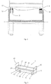
- FIG. 1 illustrates in a side view, one embodiment of the vacuum belt filter according to the invention.
- the vacuum belt filter shown in the drawings is constructed for continuous liquid-solid separation of slurry or similar feed.
- the vacuum belt filter comprises an endless belt 1 comprising a multitude of individual vacuum boxes 2 arranged one after another in the longitudinal direction of the belt.
- the vacuum boxes 2 each comprise a filter means in the form of a capillary filter the filter means preferably being formed of the capillary filter (see filter 7 in Figure 3 ).
- a capillary filter water (liquid) is kept in the micro-pores of the filter medium by the capillary forces and no flow of air takes place after the free water in the residue (e.g. filter cake) has been removed.
- the capillary action of the filter does not participate in the dewatering itself, for instance by sucking water out of the slurry.
- the capillary filter is preferably planar and stiff. With a stiff filter is here meant a rigid filter element which does not collapse inside the vacuum box 2 under the prevailing vacuum conditions, minor deformation being acceptable.
- Reference numeral 29 illustrates a feed station for feeding slurry on the belt 1 of the belt filter.
- Reference numeral 30 shows an inclined chute of the feed station 29 for feeding the slurry on the upper surface of the vacuum boxes 2 and more precisely on the filters thereof.
- the slurry can for example be coarse iron concentrate or organic slurry consisting of fine particles such as organic biomass.
- the vacuum boxes 2 follow one after another along the whole length of the belt 1, but for sake of simplicity, all vacuum boxes have not been illustrated.
- the number of vacuum boxes is dozens and more typically hundreds. No gap is present between adjacent vacuum boxes 2 at the feed station 29. This can e.g. be achieved by arranging a seal (not shown) between the vacuum boxes 2. Such a seal is positioned along one long side of the vacuum box 2.
- lateral shields preventing slurry from falling out laterally from the belt 1 are not shown in Figure 1 .
- These lateral shields, which are mounted on end walls of the vacuum box 2 are, however, seen in Figure 3 , c.f. shields 42, 43.
- the vacuum boxes 2 are arranged on a drive chain 28 of the belt 1 and supported by the drive chain so that they move at synchronized velocity with the drive chain.
- the drive chain 28 replaces the expensive and massive rubber belts known from prior art vacuum belt filters and owing to this, the costs for manufacturing the vacuum belt filter of the present invention are lower. Replacing a rubber belt with a drive chain also lowers the weight of the moving masses of the vacuum belt filter, and as a consequence, less energy is needed for moving the belt and operating the vacuum belt filter.
- Reference numeral 5 shows a suction station for applying suction to the vacuum boxes 2.
- the suction station 5 comprises a rotating distribution valve suction arrangement 24 which for sake of simplicity in the following is also called rotating suction arrangement.
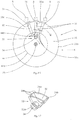
- Figure 15 shows in more detail the rotating suction arrangement 24.
- the rotating suction arrangement 24 comprises a rotating (rotatable) member 25 provided with a plurality of suction ends 26 arranged at a periphery 25a of the rotating member 25.
- the rotating member 25 is preferably circular having a circular periphery 25a, but can more generally be circumferential, i.e. it need not be fully circular having a constant radius.
- a rotating member 25 which is circular enables an easy achievable track for the belt 1 and an easy design of the supports for the belt.
- the rotating member 25 has such suction ends 26 along its entire periphery (360 degrees), but for sake of simplicity only a few suction ends 26 have been drawn in the figure.
- the suction ends 26 are arranged at a distance Z from each other which corresponds to the distance S between outlets 8 of adjacent vacuum boxes 2, c.f. Figure 1 .
- the suction ends 26 are adapted to be connected to the outlets 8 of the vacuum boxes 2 in order to apply suction to the vacuum boxes 2.
- the rotating suction arrangement 24 creates a fluid communication between a vacuum source 45 and the outlet 8 only when the suction ends 26 are connected to the outlet 8 of the vacuum boxes 2.
- the vacuum source 45 comprises a pump (not specifically shown) for creating an underpressure.
- a non-rotatable stationary distribution part 32 is via a connection part 32a (see Figure 12 ) thereof connected to the vacuum source (see reference sign 45 in Figure 1 ) and opens against an inner rim 44b of the rotating member 25 via a suction port 34.
- the inner rim 44b is circular.
- the suction port 34 of the distribution part 32 comprises a suction opening 34a which faces only a part of a multitude of openings 44a provided in the inner rim 44b of the rotating member 25.
- Said inner rim 44b forms a distribution surface 44 comprising said multitude of openings 44a. Adjacent openings 44a are arranged at a constant distance U from one another.
- the rotating member 25 is provided with conduits 35 so that each suction end 26 has its own conduit 35 leading to the suction port 34.
- Each conduit 35 comprises a first end 35a being in fluid communication with a suction end 26, and an opposite second end 35b being in fluid communication with the opening 44a of the inner rim 44b of the rotating member 25.
- the opening 44a of the distribution surface 44 comes into fluid communication with the suction opening 34a of the suction port 34 only at intervals when the rotating member 25 and the distribution surface 44 thereof are rotating.
- the shape and curvature of the suction opening 34a correspond to the shape and curvature of the inner rim 44b of the rotating member 25.
- the suction opening 34a may be bordered with seals 34b so that the suction opening 34a lies tightly and sealingly against the distribution surface 44 of the rotating member 25.
- the suction end 26 in the middle of the three suction ends 26 shown in Figure 14 is connected to the outlet 8 of a vacuum box, and only this suction end 26 applies via i) the suction port 34, ii) the conduit 35 and iii) the suction end 26 a suction to said outlet 8 (i.e. the middle outlet 8 of the shown three outlets 8 in Fig.10 ).
- the conduits 35 are preferably formed of radial channels made in the rotating member 25.
- Reference numeral 33 shows a shaft arranged centrally with respect to the rotating member 25.
- the shaft 33 is supported on bearings (not shown).
- the shaft 33 rotates, also the rotating member 25 rotates and each of the suction ends 26 comes in turn in connection with outlets 8 of the vacuum boxes.
- the shaft can be non-rotatable, whereby the member 25 is arranged to rotate relative to the shaft.
- a rotatable shaft is preferred over a non-rotatable shaft, because bearings mounted at the ends of the shaft are easy to replace (when needed); a shaft fixed to the rotating member 25 is also easy to lathe.
- reference numeral 4 indicates a drive means for driving the belt 1 by driving the drive chain 28 thereof.
- the drive means 4 comprises a turn pulley 4a which has been bearing-mounted on a frame 27 of the vacuum belt filter.
- the frame 27 has been draft with broken line.
- the drive means 4 further comprises a moving apparatus (not shown) for driving the turn pulley 4a of the drive means 4.
- the moving apparatus is preferably electrically driven (an electric motor), because an electric motor enables precise adjustment of speed of the belt 1, which, in turn, improves adjustability of the process.
- the belt 1 can be hydraulically, pneumatically, wind-, water- or biologically powered.
- a hydraulic motor provides rather precise adjustment of speed of the belt.
- the drive means 4 rotates the belt 1 with a speed of typically 0.1 m/s to 0.5 m/s.
- Reference numeral 10 in Figure 1 shows a discharge station for removing residue in the form of a filter cake from a filter media or filter 7 of the vacuum boxes 2 (the filter being indicated by reference numeral 7 in Figure 3 ).
- the vacuum boxes 2 move from the feed station 29 to the discharge station 10
- a filter cake is gradually built up on the upper surface of the filter 7 on the upper side of the vacuum box when water is removed from the slurry.
- the vacuum inside the vacuum box 2 will affect the filter cake and causes dewatering during the whole way from the suction station 5 to discharge station 10.
- Reference numeral 49 indicates a filter cake washing apparatus for washing the filter cake.
- the washing apparatus is designed to deliver clean water or other washing fluid on the filter cake.
- the design of the cake washing apparatus is not explained in more detail here, because a filter cake washing apparatus is known for a person skilled in the art.
- the washing fluid penetrates the filter cake and travels to the capillary filter where it is absorbed to the capillary filter.
- desired substances such as alkalis and salts are mixed with the washing fluid in this way cleaning the filter cake from unwanted impurities.
- the filtrate absorbed to the capillary filter is a desired end product and the filter cake is waste. In such a case, valuable substances are collected from the filter cake by washing the filter cake.
- the distance between the feed station 29 and the discharge station 10 is typically 5 m to 50 m, preferably 10 m to 30 m.
- the discharge station 10 comprises one or more scrapers 11 for removing the residue from a dirty side (the upper side) of the filter 7.
- Reference numeral 31 shows a discharge container for collecting the residue (the filter cakes).
- the container 31 is positioned under the scraper(s) 11.
- scrapers 11 other type of removal tools, such as pressurized air, can be used for removing the residue from the filters. In the case of a heavy filter cake with low adhesion to the filter media the cake discharge may take place by the gravity force upon turning around the vacuum box at the discharge station.
- Reference numeral 14 shows a backwash station for cleaning the vacuum boxes 2 and especially the filters 7 thereof after the filter cakes have been removed. Backwash of the filters is needed to maintain the permeability of the filter medium and the filtration capacity.
- the backwash station 14 is associated with a wash vat 22 into which the vacuum boxes 2 are fed.
- FIG. 3 shows a vacuum box 2 in more detail.
- the vacuum box 2 comprises a bottom 36, two opposite long sides 37, 38, two opposite short sides 39, 40, or end walls, and a top 41.
- the end walls 39, 40 are inclined so that the vacuum box 2 tapers in a direction towards its bottom 36.
- Such a tapering design is advantageous for the turning of the vacuum box 2 at the bends of the endless belt 1, i.e. over the turn pulley 4a of the drive means 4, and at the suction station 5, and at the backwash station 14.
- the tapering design provides an easy solution for enables to arrange adjacent vacuum boxes 2 and especially the filters 7 thereof close to one another at the straight portion of the belt 1 between the suction station 5 and the drive means 4 which is at the discharge station 10.
- the vacuum box 2 comprises an inside space 3 for receiving filtrate originating from the slurry.
- the residue (the filter cake) will collect on the upper surface of the vacuum boxes 2, on the capillary filter 7 thereof.
- the capillary filter media will prevent air from entering the inside space 3 of the vacuum boxes 2.
- the stiff nature of the filter media will support the filter cake and makes it possible to form a cake of a very even thickness onto the filter medium.
- the capillary filter 7 is preferably a micro porous ceramic filter preferably in the form of a stiff plate.
- a ceramic filter is stiff and has a good endurance against corrosion; it is also durable and strong.
- the filter can be a micro porous metallic or plastic filter [or other material providing capillary action and resistance against corrosion which are required in the belt filter].
- the filter need not, however, be stiff; it can be alternatively a flexible cloth, fabric or film supported from below. If the filter is flexible (a flexible cloth), it must be supported from above if backwash of the filter is carried out.
- a supported flexible filter material can be designed in a filter cartridge, which can be attached onto a frame to form a vacuum box.
- the effective filtering area of the capillary filter 7 is preferably 1 to 5 m 2 , e.g. 1 m 2 , and the volume of the vacuum box 2 is 10 l to 500 l, preferably 50 l to 200 l.
- the dimensions and volume of the vacuum box 2 can vary depending on application.
- the pore size of the filter 7 is 0.03 ⁇ m to 5 ⁇ m, preferably 0.04 ⁇ m to 3 ⁇ m, and even more preferably 0.05 ⁇ m to 2 ⁇ m calculated from the bubble point of the material for pure water.
- the bubble point refers to an effective bubble point.
- the effective bubble point describes a pressure difference between the upper surface of the capillary filter 7 (c.f. the top 41 of the vacuum box 2) and the inside surface of the capillary filter (i.e. the clean side of the capillary filter facing the inside space 3 of the vacuum box 2) at which 1 liter of air flows through one square meter of the filter surfaces during a one minute time.
- the (effective) bubble point of the capillary filter 7 is 0.9, when a 0.9 bar pressure difference is provided in such a capillary filter 7 between the outside surface of the filter and the inside surface of the capillary filter, 1 liter of air passes through a square meter of the filter surfaces during one minute. If the bubble point is 0.9 bar and the total area of the filter surfaces is 2 square meters, 2 I of water passes through the filter surfaces in one minute..
- the bubble- point of the capillary filter 7 is in the range of 0.5 bar to 1.5 bar, and preferably 0.8 bar to 1 bar. If filtering is carried out with a pressure difference which is below the bubble point, air does not penetrate the filter cake or the filter, and there is no pressure loss owing to air flow.
- the vacuum box does not function well unless the material to be filtered is highly compressible, such as organic mass (e.g. chemical pulp). If the bubble point is above 1 bar, e.g. 1.5 bar or even 3 bar, the filtering works, but the pore size is small and the flow resistance is big if the thickness of the filter material is not adjusted to be proportionally smaller.
- the capillary filter 7 is part of a replaceable filter element 50, which is described in more detail with reference to Figure 4a and Figures 4 to 6.
- Figures 4a and 4 show a vacuum box 2 with the filter element 50.
- the replaceable filter element 50 is a spare part of the vacuum belt filter.
- the replaceable filter element 50 shown in Figures 4a, 4 and 5 comprises a preferably planar capillary filter 7 comprising a first permeable filter surface 51 for receiving a feed, a second surface 53 of the capillary filter being opposite to the first filter surface, and a support structure 52 for supporting the second surface of the capillary filter.
- the capillary filter 7 is preferably rectangular.
- the width of the capillary filter 7 is 0.1 m to 0.3 m; and the length of the capillary filter is 1.5 m to 3 m, the length being 5 to 10 times the width of the capillary filter. Said length dimension is transverse to the direction to the direction of motion of the belt 1.
- the thickness of the capillary filter 7 is preferably 0.1 mm to 10 mm. If the support structure is of plastic material, the thickness of the capillary filter 7 is preferably 0.2 mm to 10 mm.
- the support structure 52 is designed to provide an even support for the capillary filter 7. Without a support structure 52 the risk of break of the capillary filter 7 is big, especially if the capillary filter is made of ceramic material.
- the support structure 52 is preferably via an intermediate layer 60 permanently attached to the second surface 53 of the capillary filter 7 and it is designed to support the capillary filter in such a way that the capillary filter does not break in use, i.e. when a pressure difference acts over the first filter surface 51 and the second surface 53 causing huge forces on the capillary filter 7.
- the intermediate layer 60 is highly preferred, because it makes it easy to attach the support structure 52 to the capillary filter 7.
- a first surface of the intermediate layer 60 faces the second surface 53 of the capillary filter 7, and a second surface of the intermediate layer being opposite to the first surface faces the support structure 52.
- the intermediate layer 60 is preferably ceramic.
- the support 52 structure for the capillary filter 7 is preferably in the form of a planar support element also called a first support element 52a in the following.
- the support structure 52 defines a cavity 56, a plurality of support parts 54 for supporting the second surface of the capillary filter being arranged in the cavity.
- the support parts 54 may preferably be shaped as studs.
- the number of support parts 54 is 50 to 4000 per square meter. If the support parts 54 have a round cross section (in a plane parallel to the plane of the planar support structure 52), the number of support parts is preferably 1000 to 4000 per square meter, more preferably 1500 to 2500 per square meter.
- the number of support parts is preferably 50 to 400 per square meter, more preferably 100 to 200 per square meter.
- the support parts 54 are spaced from one another in order to provide an even support for the capillary ceramic filter 7.
- Preferably the support parts 54 are evenly distributed below the second surface 53 of the capillary ceramic filter 7.
- the support structure 52 may be designed to prevent transfer of forces between the support parts 54.
- the support structure 52 comprises connectors 55 for connecting each support part 54 to at least one other support part, c.f. Figure 5 .
- the support structure 52 preferably forms a grid structure as one can see from Figure 5 .
- the thickness of the support structure 52 depends on many parameters, such as the surface area of the capillary filter 7. A suitable thickness is believed to be 50 mm to 200 mm.
- the support parts 54 facing the second surface 53 of the capillary filter 7 form a plurality of support surfaces against the second surface of the intermediate layer 60 and indirectly against the capillary filter 7, which support surfaces amount to 5 per cent to 60 per cent, preferably 10 per cent to 40 per cent, and more preferably 15 per cent to 25 per cent of a total area of the second surface of the capillary filter.
- the intermediate layer 60 is preferably a ceramic layer.
- the second surface of the intermediate layer 60 comprises a rough joining interface for fastening the support structure 52 permanently to the intermediate layer 60.
- the rough joining interface has a grit number of 40 to 300, preferably 40 to 180, and more preferably 60 to 120.
- Such a grit range functions especially well for fastening support parts 54 made of e.g. thermoplastic material permanently to the second surface of the intermediate layer 60 by e.g. gluing, or by melting the ends of the support parts 54 into the second surface.
- the ends of the support parts 54 are melted into the second surface of the intermediate layer 60, there is a layer comprising the material or the support structure which attaches the support structure to the rough joining interface of the intermediate layer 60.
- the support structure 32 is formed as a unit with the capillary filter 7 and one may say that the support structure is an integral part of the intermediate layer 60 and the capillary filter 7.
- the rough joining interface is formed directly, i.e. without an intermediate layer 60, to the second surface 53 of the capillary filter 7.
- the whole second surface of the intermediate layer 60 need not be roughened; it is sufficient if the second surface is, or has been roughened at points where the support parts 54 are fastened. These points form a rough joining interface.
- the thickness of the intermediate layer 60 is preferably 5 mm to 40 mm, more preferably 5 mm to 20 mm.
- connection between a support parts 54 and the second surface 53 must be sufficient for the filter element 50 to endure pressures acting on the filter element 50 especially during back washing (when the vacuum boxes are cleaned) but also during filtration.
- the connection must be strong enough to endure a pressure difference of at least 0.4 bar, preferably at least 0.7 bar.
- the pressure difference is 0.4 bar; and if the pressure outside the vacuum box 2 is 1 bar and the pressure inside the vacuum box is 1.7 bar, the pressure difference is 0.7 bar.
- the support structure 52 must be strong enough to endure a pressure difference of at least 0.4 bar, preferably at least 0.5 bar, and more preferably at least 0.6 bar over the filter element 7.
- a pressure difference of at least 0.4 bar, preferably at least 0.5 bar, and more preferably at least 0.6 bar over the filter element 7.
- Reference numeral 52b in Figures 4a, 4 and 6 is drawn to a second support element which is fixed to the body part 58 of the vacuum box 2.
- the support element 52b is preferably a planar element which is attached preferably on top of the body part 58 of the vacuum box 2.
- the support element 52b can be an integral part of the body part 58.
- the support element 52b is not part of the filter element 50 (i.e. is not part of the spare part).
- the periphery of the support element 52b can be arranged to be supported on brackets provided inside the body part 58.
- the support element 52b can be attached to the body part 58 of the vacuum box e.g. by clips (not shown) or other fastening means.
- the support element 52b is alternatively or additionally attached to the bottom of the body part 58, e.g. by bolts or other detachable fastening means. Fastening of the support element 52b to the body part 58 is not disclosed here in more detail, because a person skilled in the art readily can find out various suitable designs for such attachment.
- the support element 52b comprises a multitude of holes 57 which enable filtrate to pass into the inside space of the vacuum box 2.
- Figures 7a, 7 and 8 illustrate a second embodiment of the filter element.
- the filter element 50' of Figures 7a, 7 and 8 differs from the embodiment shown in Figure 4a and Figures 4 - 6 in that the support element 52a' is fastened not only to the intermediate layer 60, but also to the support element 52b', which thus is part of the support structure 52' and part of filter element 50'.
- Connectors, c.f. connectors 55 like those in Figure 5 are not needed, because support element 52b' connects the support parts 54'. Support element 52b' is thus also a connecting means.
- the fastening of the support element 52a' to the support element 52b' can be carried out by various manners (permanently e.g. by gluing, or detachably e.g. by snap fasteners) as appreciated by a person skilled in the art.
- the support element 52b' of Figure 8 comprises a multitude of holes 57', like support element 52b of Figure 6 .
- the support element 52b' provides additional stiffness to the support structure 52' and the filter 7' which is advantageous especially during back washing of the filter. Added stiffness is advantageous and important, because it reduces risk of the capillary filter 7' to break during back washing.
- the filter element 50' of Figures 7a, 7 and 8 is also advantageous in that it is a compact structure which can be factory built and easily mounted on site.
- the periphery of filter element 50' is arranged to be supported on brackets 59' provided inside the body part 58 of a vacuum box.
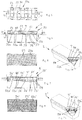
- FIGS 9 and 10 show a third embodiment of the filter element 50".
- a corner area of the filter element 50" is shown opened in the figures - only to illustrate the construction of the filter element.
- the capillary filter 7" is supported by a support structure 52" in the form of a honeycomb structure.
- the honeycomb structure comprises a multitude of spaced holes 58" defined by walls 61".
- the honeycomb structure can preferably be made of plastic, preferably thermoplastic. If the honeycomb structure is made of plastic, there is preferably an intermediate ceramic layer 60" between the filter 7" and the honeycomb structure as shown in Figures 9 and 10 .
- the intermediate ceramic layer 60" has a grit number of 40 to 300, preferably 40 to 180, more preferably 60 - 120 which grid values form a rough joining interface for attaching of the honeycomb structure to the capillary filter 7".
- the honeycomb structure can alternatively be made of e.g. ceramic material. If the support structure 52" is made of ceramic material and the capillary filter 7" is of ceramic material, no intermediate layer 60" is needed.
- the thickness of the honeycomb structure is 5 mm to 200 mm, preferably 10 mm to 150 mm.
- FIGS 11 and 12 show a fourth embodiment of the filter element.
- the filter element 50'" of Figures 11 and 12 differs from the filter element 50'" of Figures 9 and 10 essentially in that the support structure 52" is a compact piece of porous material, i.e. it does not comprise (macroscopic) holes, c.f. holes 58" in Figure 10 ..
- a corner of the filter element 50'" is shown opened to illustrate this.
- the pore size of the compact piece is bigger than the pore size of the ceramic filter 7"'.
- the piece is preferably a ceramic brick preferably made of a highly porous material. Alternatively, a compact piece of plastic or a piece of porous metal can be used.
- the capillary filter 7'" has been formed onto the brick preferably by spraying.
- the manufacturing of the filter element 50'" comprises preferably compressing a raw material to a brick, burning the brick in an oven, spraying the brick with a ceramic membrane layer, and finally burning the brick with the membrane layer in an oven.
- the brick has a grit number of 40 to 300, preferably 40 to 180, more preferably 60 to 120. If the brick is manufactured of a material having an average grit number e.g. 100, one hundred particles arranged in a row fill up a distance of one inch. Alternatively, the brick could be glued to the capillary filter 7"'. If glued, the filter surface facing the brick should be rough, preferably having a grit number of 40 to 180, and more preferably 60 to 120, in order to achieve a strong bond.
- the thickness of the brick is preferably 10 mm to 100 mm.
- the thickness of the capillary filter 7'" is preferably 0.1 mm to 10 mm, preferably 0.1 mm to 7 mm.
- the vacuum boxes and the filters 7 thereof can easily be individually replaced in contrast to a conventional vacuum belt filter employing a filter cloth as filtering media.
- a whole worn filter cloth worn e.g. owing to stretching
- the length of which typically is dozens of meters the replacement being cumbersome and time consuming.
- the outlet 8 of the vacuum box 2 has a check valve 9 which enables fluid to be withdrawn from the inside space 3 of the vacuum box out from the vacuum box via the outlet.
- the check valve 9 is illustrated in Figure 14 in more detail.
- the check valve 9 comprises a spring 46 which urges a blocking member 9a of the check valve 9 against a seat.
- the spring 46 is a helical spring, but other types of springs can be employed. When the spring 46 is in its maximally extended position, the check valve 9 is closed, and no fluid (liquid, gas or other substance) may enter from the inside space 3 of the vacuum box 2 to the outside of the vacuum box through the outlet 8. When the pressure from the inside space 3 of the vacuum box 2 exceeds the pressure created by the spring 46 against the blocking member 9a, the check valve 9 is open.
- a rubber spring can be used; or cup springs.
- a gas spring instead of a spring loaded check valve having a separate spring which activates the movement of a blocking member, other types of check valves can be used.
- the check valve can function based on the design of e.g. a membrane, clack, a poppet, a goose neck, whereby the valve itself functions like a spring.
- the check valve 9 comprises a mechanical actuator for closing a blocking member.
- the check valve can e.g. be a solenoid valve (which may be energized from outside), a mechanically controlled valve, a pneumatically controlled valve and/or a hydraulically controlled valve.
- the spring 46 or other mechanical actuator is not indispensable, because the blocking member 9a can owing to underpressure within the inside space 3 of the vacuum box 2 be kept in a blocking position.
- the basic structure of the check valve may be based on e.g. a membrane, a clack, a poppet, a goose neck, a ball, a slide, a flex hose, a needle or any other type of valve known per se.
- Reference numeral 13 indicates an inlet of the vacuum box 2.
- Figure 13 shows a spring loaded check valve 15 in the inlet 13.
- a spring 16 of the check valve 15 urges a blocking member 15a of the check valve 15 against a seat.
- the spring 16 is a helical spring, but other types of springs can be employed as explained above for spring 46.
- the check valve 15 When the spring 16 is in its extended position, the check valve 15 is closed, and no fluid (liquid, gas or other substance) may enter to the inside space 3 of the vacuum box 2.
- the blocking member 15a By applying on the blocking member 15a an external force which is opposite to the force of the spring 16, the blocking member 15a can be displaced in a direction towards the spring 16 (i.e. upwards in Figure 13 ), whereby the spring flexes and the check valve 15 opens.
- check valve 15 In order that the check valve 15 opens, the pressure acting from the outside of the vacuum box 2 on the blocking member 15a must be bigger than the force of the spring and the pressure acting from the inside of the vacuum box on the blocking member.
- check valve 9 instead of a spring loaded check valve 15 having a separate spring which activates the movement of a closing member, other types of check valves can be used. More generally defined, the check valve 15 comprises a mechanical actuator for closing a blocking member.
- the inside space (see reference numeral 3 in Figure 3 ) of the vacuum boxes 2 have the same pressure as the surrounding atmosphere, i.e. 1 atmosphere (1 bar). However, the inside space can have a pressure deviating from the pressure of the surrounding atmosphere.
- vacuum box 2a illustrates a vacuum box entering the suction station 5.
- the inlet 13 of the vacuum box 2a will not open but is kept closed owing to the spring 16 of the spring loaded check valve 15, c.f. Figures 3 and 13 .
- the spring force of the spring 16 must be bigger than the force of the suction in order to keep the inlet 13 closed during suction and in order to create and maintain an underpressure within the vacuum box 2a.
- An absolute pressure of 0.05 bar to 0.5 bar, preferably 0.05 bar to 0.15 bar is created within the vacuum box 2.
- check valves 9, 15 When check valves 9, 15 are closed, no fluid (liquid, gas or other substance) can enter the inside 3 of the vacuum box 2 through the check valves 9, 15.
- Check valve 9 is closed when the pressure at the outlet of the check valve 9 is higher than the pressure at the inside space 3 of the vacuum box 2 the spring 46 providing an additional force to displace the blocking member 9a into the closed position (shown in Figure 14 ).
- Spring 16 keeps check valve 15 closed when there is an underpressure within the vacuum box 2.
- the check valves 9, 15 enable to maintain an underpressure inside the vacuum box 2 when it travels from the suction station 5 to the discharge station 10.
- the vacuum box 2 can be called a vacuum accumulator. Owing to the underpressure within the vacuum box 2, a slurry will continuously be filtered when the vacuum box moves between the feed station 29 and the discharge station 10, i.e. without any fluid communication between the inside space 3 of the vacuum box 2 and the suction station 5.
- a filtrate i.e. water or other liquid
- water from the slurry is transported into the vacuum box 2 through the capillary action of the filter 7.
- a residue is collected and built up on the upper side of the vacuum box 2 on the upper side of the filter 7.
- filtrate water
- the volume of gas in the inside space 3 of the vacuum box will gradually decrease and consequently the absolute pressure within the vacuum box will increase. If, for example, the initial absolute pressure within the vacuum box 2 is 0.05 bar at the suction station 5, and the gas volume is reduced by for example 20% during filtration, the absolute pressure in the vacuum box 2 will increase to 0.25 bar.
- a dewatering station 47a is positioned between the suction station 5 and the discharge station 10.
- the construction of the dewatering station 47a is similar to the concentration of the suction station 5.
- the dewatering station 47a has in Figure 1 been drawn as a box.
- filtrate can be removed from the inside space 3 of the vacuum box 2 by opening the check valve 15 and/or the check valve 9.
- Outlet 8 and the check valve 9 therein are the primary components for removal of filtrate.
- the additional suction station 5b is of the same type as the suction station 5, i.e. it has a stationary distribution part (not shown), conduits, suction ends etc., like the suction station 5.
- the additional suction station 5b typically can be used for removing filtrate from the vacuum boxes 2, it can be called a dewatering station.
- the location of the additional suction station 5b can be chosen relatively freely between the discharge station 10 and the feed station 29.
- the additional suction station 5b is not indispensable, but it makes the liquid-solid separation of slurry much faster.
- Reference numeral 47b shows an additional dewatering station positioned between the additional suction station 5b and the discharge station 10.
- the construction of the additional dewatering station 47b is similar to the construction of the dewatering station 47a.
- the number of dewatering stations can vary; typically there is zero to three dewatering stations, preferably one to three dewatering stations in the vacuum belt filter.
- the upper region of the belt 1 is inclined downward by preferably 1 degree to 10 degrees with respect to the horizontal downstream the suction station 5.
- the belt is inclined up to the location of the discharge station 10. Thanks to the inclination, slurry is not drift - at least to a higher extent - on the vacuum boxes 2 in a direction opposite to the travel direction of the belt 1. This prevents slurry from entering backwards to the suction station 5 and falling down downstream the suction station.
- the moisture content of the residue can e.g. be 40% to 50% close to the feed station 5, and when the residue comes to the discharge station 10, the moisture content of the residue is 5 to 25% depending on nature and size of particles, and the residue is in the form of a filter cake.
- a low moisture content is especially of importance for example in filtering organic materials with high specific filtration resistance, such as biomass, organic waste or algae in energy production.
- the thickness of the filter cake can be dozens of millimeters when the vacuum box 2 enters the discharge station 10.
- the weight of the filter cake depends on filtering area, type of slurry etc.; it can e.g. be 5 kg when it enters the discharge station 10.
- the residue is removed by the scrapers 11 and is discharged to the discharge container 31 underneath.
- the upper surface of the filter 7 of the vacuum box 2 is preferably sprayed with wash fluid, typically water.
- Reference numeral 12 shows the spray means for carrying out said cleaning.
- the spray means 12 comprise nozzles for spraying water against the upper surface of the filter 7.
- the spraying pressure can be e.g. 5 bar to 10 bar.
- the water can be at least partly taken from one or more of the following stations: the dewatering station 47a, the additional suction station 5b, the additional dewatering station 47b, and the backwash station 14.
- the vacuum boxes 2 are cleaned in the backwash station 14.
- the construction of the backwash station 14 is similar to the construction of the suction station, i.e. it comprises a non-rotatable stationary distribution part 48 corresponding to the stationary distribution part 32 of the suction station 5, and a rotating member 6 corresponding to the rotating member 25 of the suction station 5; it comprises a rotating distribution valve arrangement 17 having a construction which preferably is similar to the construction of the rotating suction arrangement 24 of the suction station 5.
- the rotating member 6 of the rotating distribution valve arrangement 17 comprises a rotating periphery 21 provided with a plurality of distribution ends 19 arranged along the entire periphery 21 of the rotating member 6, but for sake of simplicity only two distribution ends have been drawn in Figure 1 .
- the distribution ends 19 are arranged at a distance X from each other corresponding to the distance Y between the inlets 13 of adjacent vacuum boxes 2.
- the distribution ends 19 are adapted to be connected to the inlets 13 of the vacuum boxes 2 in order to feed wash fluid to the inside space 3 of the vacuum boxes 2.
- the rotating distribution valve arrangement 17 is provided with a valve system which is (as explained in more detail below) adapted to open fluid communication between a wash fluid source (possibly containing wash fluid from the dewatering station) and the distribution ends 19 only when the distribution ends 19 are connected to the inlets 13 of the vacuum boxes.
- the rotating member 6 of the rotating distribution valve arrangement 17 comprises further an inner rim 18 corresponding to the inner rim 44b of the rotating member 25 of the suction arrangement 5 and conduits (not shown) corresponding to conduits 35 of the rotating suction arrangement 24 of the suction arrangement 5.
- the opening (not shown) of the stationary distribution part 48 has a shape and curvature which corresponds to the shape and curvature of the inner rim 18 to provide effective fluid communication between the stationary distribution part 48 and the channels (not shown) in the rotating member 6.
- the inner rim 18 is preferably circular (like the inner rim 44b of the rotating member 25).
- the inlet 13 of the vacuum box comes into contact with the distribution ends 19 of the backwash station 14.
- the distribution ends 19 are adapted to press the blocking member 15a of the check valve 15 so that the check valve 15 opens for enabling wash water to enter to the inside space 3 of the vacuum box 2. It is conceivable that the distribution ends 19 are adapted not to press the blocking member 15a but to press only against the inlet 13, which is possible if the pressure of the wash fluid is high enough to open the check valve 15 against the spring force of the check valve.
- the outlet 8 shall be closed at least partly so that water does not forcefully flow out from the outlet 8.
- the spring 46 in the outlet 8 partly serves for such closing.
- the spring 46 provides only for a minimal closing effect, because a low opening pressure for check valve 9 is wanted as a near absolute vacuum in to the vacuum box is strived at.
- the outlet 8 of the vacuum box 2 can, however, effectively be closed by a blocking element 20 arranged on a rotating periphery 21 of the rotating distribution valve arrangement 17.
- Said periphery is preferably the same periphery as the one having the distribution ends 19.
- Blocking elements 20 are arranged along the entire periphery 21 of the rotating distribution valve arrangement 17, but for sake of simplicity only two blocking elements have been drawn in Figure 1 .
- the blocking elements 20 are arranged at a distance L from each other corresponding to the distance T between the outlets 8 of adjacent vacuum boxes 2.
- the blocking elements 20 are adapted to engage the outlets 8 and close them forcefully to prevent wash fluid from flowing from the inside space 3 of the vacuum box out from the outlets 8 of the vacuum boxes 2.
- the blocking elements 20 are adopted to close the outlets 8 by closing the check valves 9.
- the check valves 9 can be forcefully closed when the blocking elements 20 are engaged with the check valves 9. If no blocking elements 20 are arranged in the outlets 8, wash fluid can freely flow out from the outlets 8 through the check valves 9.
- the backwash pressure should be higher than the differential pressure used in filtration.
- the cleaning of the vacuum boxes 2 can normally be carried out with an over-pressure of 1 to 2 bar.
- FIG 2 illustrates the above described opening of inlets 13 by the aid of the distribution ends 19 of the distribution valve arrangement 17 and illustrates also the blocking of the outlets 8 with blocking elements 20 at the backwash station 14.
- the vacuum boxes 2 pass a wash vat 22 arranged in connection with the backwash station 14.
- ultrasonic transducers 23 are arranged in the wash vat 22 for applying sound waves to the filters 7 of the vacuum boxes 2.
- the filters 7 of the vacuum boxes 2 are washed (cleaned) with acids. This is possible, because the filters 7 are made from a material which stands acids, e.g. a ceramic material such as Al 2 O 3 , SIC, aluminium silicate, and titania.
- the material of the filter can also be metal or plastic having the required mechanical strength and corrosion resistance.
- the vacuum boxes 2 arrive to the suction station 5 for being connected to the rotating distribution valve suction arrangement 24 of the suction station 5.
- an underpressure is created into the vacuum boxes 2 as described above.
- the vacuum belt filter is covered with a hood (not shown) if poisonous gases are formed in the liquid-solid separation carried out by the vacuum belt filter.
- a major advantage with the belt filter of the present invention is that all capillary filters must not be replaced at the same time; it is expected to be sufficient that only one or a few capillary filters which have worn or broken are replaced.
- a worn or broken capillary filter can easily and fast be replaced by detaching from the belt 1 a respective vacuum box 2 having the worn or broken capillary filter and putting in its place on the belt 1 a new vacuum box having a new capillary filter.
- the worn or broken capillary filter is detached from the vacuum box 2 while keeping the vacuum box attached to on the belt 1, and a new capillary filter is attached to the vacuum box on the belt.
- check valves 9 of the vacuum boxes 2 wear in use or may break, they must at some time be replaced. Not all check valves of the vacuum boxes must not be replaced at the same time; only a check valve which is replaced.
- a worn or broken check valve 9 can be replaced by detaching from the belt 1 a respective vacuum box 2 having the worn or broken check valve and putting in its place on the belt 1 a new vacuum box having a new check valve.
- a worn or broken check valve 9 is detached from the vacuum box 2 while keeping the vacuum box attached to on the belt 1, and a new check valve is mounted to the vacuum box on the belt.
- the method for carrying out liquid-solid separation of the slurry in the vacuum belt filter according to the invention comprises the essential method steps as follows:
- the belt 1 with its vacuum boxes 2 travel in one and the same direction of travel in a circular motion the vacuum boxes thus forming an endless belt and a closed loop, whereby the separation process preferably is continuous.
- the suction station 5 is positioned downstream the discharge station 10 (seen in the direction of the moving belt 1).
- the belt 1 (with its vacuum boxes 2) can be moved intermittently back and forth.
- moving the belt 1 intermittently is considered not to be very effective in comparison with a continuous process where the belt moves continuously in one and the same direction; an intermittent process requires also a modification fo the lay out of the components of the vacuum belt filter shown in the drawings.
- the method for carrying out liquid-solid separation of the slurry in the vacuum belt filter comprises additionally the steps of backwashing the boxes and preferably also spraying cleaning fluid, typically water, on the upper surface of the capillary filters 7.
- cleaning fluid typically water
- each vacuum box has no inlet which is separate from the outlet.
- the suction station does is not necessarily of the type comprising a rotating member having a plurality of suction ends, although this is highly preferable.
- the distribution surface (44) of the suction station (5) need not to be formed on an inner rim (44b) of the rotating member (25) of the rotating suction arrangement (24), but can e.g. be an end surface which is perpendicular to the central axis of the rotating member (25).
- the number of conduits (35) in the rotating member (25) can vary.
- Spray means (12) between the discharge station (10) and the backwash station (14) are optional.
- the vacuum belt filter need not necessarily have a backwash station (14) although it is highly recommendable.
- a backwash station (14) is present, the components of the backwash station can vary; e.g. transducers are not necessary for cleaning the filters and vacuum boxes; it is conceivable to clean the filters with an acid.
- the number of vacuum boxes and the length of the belt can largely vary depending on application.
- An endless belt (1) is the most practical solution as all unit processes involved in the filtration cycle can be stationary organized.
- the belt (1) need not be an endless belt although an endless belt is highly recommendable; thus, the belt can be a belt arranged to move intermittently back and forth, whereby the vacuum boxes move intermittently between the suction station (5) and the discharge station (10).
- a reciprocating process is a complicated solution and it may typically also not be continuous, which may weaken the efficiency of the liquid-solid separation process.
- the number of backwash stations (14) can vary.
- One or more filter cake washing apparatuses (49) positioned upstream the discharge station (10) can be included in the vacuum belt filter.
- the vacuum belt filter comprises a cake washing apparatus and an additional suction station (5b)
- the latter should be positioned downstream the cake washing apparatus so that water sprayed on the filter cake has time to be absorbed into the filter cake and through the filter cake to the inside space (3) of the vacuum box (2); and the water can subsequently be removed from the inside space (3) through the outlet (8) of the vacuum box (2).
Description
- Filtration is a widely used process in which a solid-liquid mixture, such as a slurry or sludge, is forced against a filtering media, with the solids retaining on the filtering media and the liquid phase passing through. The present invention relates more precisely to a vacuum box and a vacuum belt filter. Vacuum belt filters are conveyor-type filters widely used in the dewatering of slurries. The invention relats further to servicing a vacuum belt filter and to a mehtod for liquid-solid separation of slurry in a belt filter. The invention relates further to a filter element. With vacuum is here understood a pressure below a surrounding pressure which typically, but not necessarily, is the atmospheric pressure of 1 bar. Related documents for the present application are
DE 29 17 897 A1 ,US 2007/227956 A1 ,CN 203 463 731 U andCN 203 082 279 U . - It is an object of the present invention to provide a new type of vacuum belt filter and a new method for liquid-solid separation, said belt filter having a simple construction enabling liquid-solid separation with low energy consumption and having long service interval. It is further an object of the present invention to provide a filter element and a vacuum box for building the vacuum belt filter of the invention, and a method for servicing the vacuum belt filter of the invention, the vacuum box being capable of maintaining an underpressure within its inside space without being connected to a vacuum source. With the expression vacuum source is here meant a source capable of creating into the vacuum boxes a pressure which is below the surrounding pressure, typically below the atmospheric pressure of 1 bar.
- In order to achieve these objects, the belt filter, the vacuum box, and the filter element have a construction as defined in the appended, respective independents claims, and the method for servicing and carrying out liquid-solid separation are characterized by the features defined in the respective independent method claims. Preferred embodiments of the vacuum belt filter, the vacuum box, the filter element and the method for liquid-solid separation of a slurry are disclosed in the appended, respective dependent claims.
- A capillary filter refers to a filter the structure and/or the material of which enables a certain amount of liquid, such as water, to be retained in the filter by a capillary action despite a differential pressure formed by a gas surrounding the filter. The liquid may be retained in the micro-pores provided in the filter. A capillary filter enables the liquid to be filtered to easily flow through the filter, but when all free liquid, such as the free liquid entering the filter has passed through the filter, the remaining liquid retained in the filter by the capillary action prevents flow of gas, such as air, through the wet filter.
- A major advantage of the vacuum belt filter, the vacuum box and the filter element of the invention is that they enable liquid-solid separation at low energy costs and the servicing interval of the belt filter is long, because the lifetime of the filters of the belt filter is long. The vacuum box of the vacuum belt filter has a simple construction making it, and also the belt filter, easy to build. The belt filter can be operated with an extremely small vacuum pump this meaning essential energy savings. Despite this, a high underpressure, i.e. a low absolute pressure, can be created within the vacuum box. Service and repair of the belt filter is easy. The vacuum boxes can be replaced individually without a need to replace all the vacuum boxes if one or more of the vacuum boxes is a need of repair. Filtration can continue within the vacuum boxes without continuous vacuum feed. Moreover, the vacuum belt filter according to invention is suitable for long cake drying periods because the length of the belt can be selected freely. In the vacuum belt filter according to invention a total filter media is divided into a large number of vacuum boxes each working as an individual dewatering element. In the vacuum belt filter according to invention the differential pressure responsible for the dewatering is effective over the whole length of the belt from vacuum station to discharge station. This is the most efficient way of achieving lowest cake moisture. In the vacuum belt filter according to invention leakage of air between the filter media and the vacuum box does not appear and a differential pressure over the filter cake is maintained. Hence, as the vacuum source does not have to compensate for leakage, the dewatering of the filter cake is efficient and energy consumption is low.
- The invention is described in closer detail with reference to the accompanying drawing in which:
-
Figure 1 illustrates in a side view of a vacuum belt filter according to the invention, -
Figure 2 illustrates a part of the backwash station of the vacuum belt filter ofFigure 1 , -
Figure 3 illustrates a vacuum box of the vacuum belt filter ofFigure 1 , -
Figures 4a, 4 and 5 show in more detail a vacuum box and a first embodiment of the filter element of the vacuum box ofFigure 3 , -
Figure 6 shows a support element for supporting the filter element ofFigures 4 and 5 in the vacuum box ofFigure 3 , -
Figures 7a, 7 and 8 show in more detail a vacuum box and a second embodiment of the filter element of the vacuum box ofFigure 3 in a side view and in a sectional view taken along section VIII - VIII ofFigure 7 , respectively, -
Figures 9 and 10 show a third embodiment of the filter element of the vacuum box in two different perspective views, -
Figures 11 and 12 show a fourth embodiment of the filter element of the vacuum box in two different perspective views, -
Figure 13 illustrates a check valve of the vacuum box ofFigure 3 , -
Figure 14 illustrates a check valve in an outlet of the vacuum box ofFigure 3 , -
Figure 15 illustrates a suction station in an inlet of the vacuum belt filter ofFigure 1 , and -
Figure 16 shows a stationary distribution part of the suction arrangement. -
Figure 1 illustrates in a side view, one embodiment of the vacuum belt filter according to the invention. The vacuum belt filter shown in the drawings is constructed for continuous liquid-solid separation of slurry or similar feed. The vacuum belt filter comprises an endless belt 1 comprising a multitude ofindividual vacuum boxes 2 arranged one after another in the longitudinal direction of the belt. Thevacuum boxes 2 each comprise a filter means in the form of a capillary filter the filter means preferably being formed of the capillary filter (seefilter 7 inFigure 3 ). In a capillary filter, water (liquid) is kept in the micro-pores of the filter medium by the capillary forces and no flow of air takes place after the free water in the residue (e.g. filter cake) has been removed. The capillary action of the filter does not participate in the dewatering itself, for instance by sucking water out of the slurry. The capillary filter is preferably planar and stiff. With a stiff filter is here meant a rigid filter element which does not collapse inside thevacuum box 2 under the prevailing vacuum conditions, minor deformation being acceptable.Reference numeral 29 illustrates a feed station for feeding slurry on the belt 1 of the belt filter.Reference numeral 30 shows an inclined chute of thefeed station 29 for feeding the slurry on the upper surface of thevacuum boxes 2 and more precisely on the filters thereof. The slurry can for example be coarse iron concentrate or organic slurry consisting of fine particles such as organic biomass. - The
vacuum boxes 2 follow one after another along the whole length of the belt 1, but for sake of simplicity, all vacuum boxes have not been illustrated. The number of vacuum boxes is dozens and more typically hundreds. No gap is present betweenadjacent vacuum boxes 2 at thefeed station 29. This can e.g. be achieved by arranging a seal (not shown) between thevacuum boxes 2. Such a seal is positioned along one long side of thevacuum box 2. Further, for the sake of simplicity, lateral shields preventing slurry from falling out laterally from the belt 1 are not shown inFigure 1 . These lateral shields, which are mounted on end walls of thevacuum box 2, are, however, seen inFigure 3 , c.f.shields vacuum boxes 2 are arranged on adrive chain 28 of the belt 1 and supported by the drive chain so that they move at synchronized velocity with the drive chain. Thedrive chain 28 replaces the expensive and massive rubber belts known from prior art vacuum belt filters and owing to this, the costs for manufacturing the vacuum belt filter of the present invention are lower. Replacing a rubber belt with a drive chain also lowers the weight of the moving masses of the vacuum belt filter, and as a consequence, less energy is needed for moving the belt and operating the vacuum belt filter. -
Reference numeral 5 shows a suction station for applying suction to thevacuum boxes 2. Thesuction station 5 comprises a rotating distributionvalve suction arrangement 24 which for sake of simplicity in the following is also called rotating suction arrangement.Figure 15 shows in more detail therotating suction arrangement 24. Therotating suction arrangement 24 comprises a rotating (rotatable)member 25 provided with a plurality of suction ends 26 arranged at aperiphery 25a of the rotatingmember 25. The rotatingmember 25 is preferably circular having acircular periphery 25a, but can more generally be circumferential, i.e. it need not be fully circular having a constant radius. However, a rotatingmember 25 which is circular enables an easy achievable track for the belt 1 and an easy design of the supports for the belt. The rotatingmember 25 has such suction ends 26 along its entire periphery (360 degrees), but for sake of simplicity only a few suction ends 26 have been drawn in the figure. The suction ends 26 are arranged at a distance Z from each other which corresponds to the distance S betweenoutlets 8 ofadjacent vacuum boxes 2, c.f.Figure 1 . The suction ends 26 are adapted to be connected to theoutlets 8 of thevacuum boxes 2 in order to apply suction to thevacuum boxes 2. Therotating suction arrangement 24 creates a fluid communication between avacuum source 45 and theoutlet 8 only when the suction ends 26 are connected to theoutlet 8 of thevacuum boxes 2. Thevacuum source 45 comprises a pump (not specifically shown) for creating an underpressure. The effect of the pump can be surprisingly low; an effect of 1 to 5 kW is sufficient for filtering means having a total filtering area of approximately 20 m2 to 100 m2. A non-rotatablestationary distribution part 32 is via aconnection part 32a (seeFigure 12 ) thereof connected to the vacuum source (seereference sign 45 inFigure 1 ) and opens against aninner rim 44b of the rotatingmember 25 via asuction port 34. Preferably theinner rim 44b is circular. As can be seen fromFigures 15 and 16 , thesuction port 34 of thedistribution part 32 comprises asuction opening 34a which faces only a part of a multitude of openings 44a provided in theinner rim 44b of the rotatingmember 25. Saidinner rim 44b forms adistribution surface 44 comprising said multitude of openings 44a. Adjacent openings 44a are arranged at a constant distance U from one another. The rotatingmember 25 is provided withconduits 35 so that eachsuction end 26 has itsown conduit 35 leading to thesuction port 34. Eachconduit 35 comprises afirst end 35a being in fluid communication with asuction end 26, and an oppositesecond end 35b being in fluid communication with the opening 44a of theinner rim 44b of the rotatingmember 25. The opening 44a of thedistribution surface 44 comes into fluid communication with thesuction opening 34a of thesuction port 34 only at intervals when the rotatingmember 25 and thedistribution surface 44 thereof are rotating. In order to provide effective fluid communication and effective suction the shape and curvature of thesuction opening 34a correspond to the shape and curvature of theinner rim 44b of the rotatingmember 25. - The
suction opening 34a may be bordered withseals 34b so that thesuction opening 34a lies tightly and sealingly against thedistribution surface 44 of the rotatingmember 25. InFigure 15 only thesuction end 26 in the middle of the three suction ends 26 shown inFigure 14 is connected to theoutlet 8 of a vacuum box, and only thissuction end 26 applies via i) thesuction port 34, ii) theconduit 35 and iii) the suction end 26 a suction to said outlet 8 (i.e. themiddle outlet 8 of the shown threeoutlets 8 inFig.10 ). Theconduits 35 are preferably formed of radial channels made in the rotatingmember 25. -
Reference numeral 33 shows a shaft arranged centrally with respect to the rotatingmember 25. Theshaft 33 is supported on bearings (not shown). When theshaft 33 rotates, also the rotatingmember 25 rotates and each of the suction ends 26 comes in turn in connection withoutlets 8 of the vacuum boxes. Alternatively the shaft can be non-rotatable, whereby themember 25 is arranged to rotate relative to the shaft. A rotatable shaft is preferred over a non-rotatable shaft, because bearings mounted at the ends of the shaft are easy to replace (when needed); a shaft fixed to the rotatingmember 25 is also easy to lathe. - In
Figure 1 reference numeral 4 indicates a drive means for driving the belt 1 by driving thedrive chain 28 thereof. The drive means 4 comprises aturn pulley 4a which has been bearing-mounted on aframe 27 of the vacuum belt filter. Theframe 27 has been draft with broken line. The drive means 4 further comprises a moving apparatus (not shown) for driving theturn pulley 4a of the drive means 4. The moving apparatus is preferably electrically driven (an electric motor), because an electric motor enables precise adjustment of speed of the belt 1, which, in turn, improves adjustability of the process. Alternatively, the belt 1 can be hydraulically, pneumatically, wind-, water- or biologically powered. A hydraulic motor provides rather precise adjustment of speed of the belt. The drive means 4 rotates the belt 1 with a speed of typically 0.1 m/s to 0.5 m/s. -
Reference numeral 10 inFigure 1 shows a discharge station for removing residue in the form of a filter cake from a filter media orfilter 7 of the vacuum boxes 2 (the filter being indicated byreference numeral 7 inFigure 3 ). When thevacuum boxes 2 move from thefeed station 29 to thedischarge station 10, a filter cake is gradually built up on the upper surface of thefilter 7 on the upper side of the vacuum box when water is removed from the slurry. The vacuum inside thevacuum box 2 will affect the filter cake and causes dewatering during the whole way from thesuction station 5 to dischargestation 10. -
Reference numeral 49 indicates a filter cake washing apparatus for washing the filter cake. The washing apparatus is designed to deliver clean water or other washing fluid on the filter cake. The design of the cake washing apparatus is not explained in more detail here, because a filter cake washing apparatus is known for a person skilled in the art. The washing fluid penetrates the filter cake and travels to the capillary filter where it is absorbed to the capillary filter. When the washing fluid travels through the filter cake, desired substances, such as alkalis and salts are mixed with the washing fluid in this way cleaning the filter cake from unwanted impurities. Sometimes the filtrate absorbed to the capillary filter is a desired end product and the filter cake is waste. In such a case, valuable substances are collected from the filter cake by washing the filter cake. - The distance between the
feed station 29 and thedischarge station 10 is typically 5 m to 50 m, preferably 10 m to 30 m. Thedischarge station 10 comprises one ormore scrapers 11 for removing the residue from a dirty side (the upper side) of thefilter 7.Reference numeral 31 shows a discharge container for collecting the residue (the filter cakes). Thecontainer 31 is positioned under the scraper(s) 11. Instead ofscrapers 11 other type of removal tools, such as pressurized air, can be used for removing the residue from the filters. In the case of a heavy filter cake with low adhesion to the filter media the cake discharge may take place by the gravity force upon turning around the vacuum box at the discharge station. -
Reference numeral 14 shows a backwash station for cleaning thevacuum boxes 2 and especially thefilters 7 thereof after the filter cakes have been removed. Backwash of the filters is needed to maintain the permeability of the filter medium and the filtration capacity. Thebackwash station 14 is associated with awash vat 22 into which thevacuum boxes 2 are fed. -
Figure 3 shows avacuum box 2 in more detail. Thevacuum box 2 comprises a bottom 36, two oppositelong sides short sides end walls vacuum box 2 tapers in a direction towards its bottom 36. Such a tapering design is advantageous for the turning of thevacuum box 2 at the bends of the endless belt 1, i.e. over theturn pulley 4a of the drive means 4, and at thesuction station 5, and at thebackwash station 14. The tapering design provides an easy solution for enables to arrangeadjacent vacuum boxes 2 and especially thefilters 7 thereof close to one another at the straight portion of the belt 1 between thesuction station 5 and the drive means 4 which is at thedischarge station 10. A tapering design is, however, not mandatory. Thevacuum box 2 comprises aninside space 3 for receiving filtrate originating from the slurry. The residue (the filter cake) will collect on the upper surface of thevacuum boxes 2, on thecapillary filter 7 thereof. The capillary filter media will prevent air from entering theinside space 3 of thevacuum boxes 2. The stiff nature of the filter media will support the filter cake and makes it possible to form a cake of a very even thickness onto the filter medium. Thecapillary filter 7 is preferably a micro porous ceramic filter preferably in the form of a stiff plate. A ceramic filter is stiff and has a good endurance against corrosion; it is also durable and strong. Alternatively, the filter can be a micro porous metallic or plastic filter [or other material providing capillary action and resistance against corrosion which are required in the belt filter]. The filter need not, however, be stiff; it can be alternatively a flexible cloth, fabric or film supported from below. If the filter is flexible (a flexible cloth), it must be supported from above if backwash of the filter is carried out. A supported flexible filter material can be designed in a filter cartridge, which can be attached onto a frame to form a vacuum box. The effective filtering area of thecapillary filter 7 is preferably 1 to 5 m2, e.g. 1 m2, and the volume of thevacuum box 2 is 10 l to 500 l, preferably 50 l to 200 l. The dimensions and volume of thevacuum box 2 can vary depending on application. The pore size of thefilter 7 is 0.03 µm to 5 µm, preferably 0.04 µm to 3 µm, and even more preferably 0.05 µm to 2 µm calculated from the bubble point of the material for pure water. The bubble point refers to an effective bubble point. The effective bubble point describes a pressure difference between the upper surface of the capillary filter 7 (c.f. the top 41 of the vacuum box 2) and the inside surface of the capillary filter (i.e. the clean side of the capillary filter facing theinside space 3 of the vacuum box 2) at which 1 liter of air flows through one square meter of the filter surfaces during a one minute time. In other words, if the (effective) bubble point of thecapillary filter 7 is 0.9, when a 0.9 bar pressure difference is provided in such acapillary filter 7 between the outside surface of the filter and the inside surface of the capillary filter, 1 liter of air passes through a square meter of the filter surfaces during one minute. If the bubble point is 0.9 bar and the total area of the filter surfaces is 2 square meters, 2 I of water passes through the filter surfaces in one minute.. The bubble- point of thecapillary filter 7 is in the range of 0.5 bar to 1.5 bar, and preferably 0.8 bar to 1 bar. If filtering is carried out with a pressure difference which is below the bubble point, air does not penetrate the filter cake or the filter, and there is no pressure loss owing to air flow. If the bubble point is low, e.g. much below 0.5 bar, the vacuum box does not function well unless the material to be filtered is highly compressible, such as organic mass (e.g. chemical pulp). If the bubble point is above 1 bar, e.g. 1.5 bar or even 3 bar, the filtering works, but the pore size is small and the flow resistance is big if the thickness of the filter material is not adjusted to be proportionally smaller. - The
capillary filter 7 is part of areplaceable filter element 50, which is described in more detail with reference toFigure 4a and Figures 4 to 6. Figures 4a and 4 show avacuum box 2 with thefilter element 50. Thereplaceable filter element 50 is a spare part of the vacuum belt filter. Thereplaceable filter element 50 shown inFigures 4a, 4 and 5 comprises a preferablyplanar capillary filter 7 comprising a firstpermeable filter surface 51 for receiving a feed, asecond surface 53 of the capillary filter being opposite to the first filter surface, and asupport structure 52 for supporting the second surface of the capillary filter. Thecapillary filter 7 is preferably rectangular. The width of thecapillary filter 7 is 0.1 m to 0.3 m; and the length of the capillary filter is 1.5 m to 3 m, the length being 5 to 10 times the width of the capillary filter. Said length dimension is transverse to the direction to the direction of motion of the belt 1. The thickness of thecapillary filter 7 is preferably 0.1 mm to 10 mm. If the support structure is of plastic material, the thickness of thecapillary filter 7 is preferably 0.2 mm to 10 mm. Thesupport structure 52 is designed to provide an even support for thecapillary filter 7. Without asupport structure 52 the risk of break of thecapillary filter 7 is big, especially if the capillary filter is made of ceramic material. Thesupport structure 52 is preferably via anintermediate layer 60 permanently attached to thesecond surface 53 of thecapillary filter 7 and it is designed to support the capillary filter in such a way that the capillary filter does not break in use, i.e. when a pressure difference acts over thefirst filter surface 51 and thesecond surface 53 causing huge forces on thecapillary filter 7. Theintermediate layer 60 is highly preferred, because it makes it easy to attach thesupport structure 52 to thecapillary filter 7. A first surface of theintermediate layer 60 faces thesecond surface 53 of thecapillary filter 7, and a second surface of the intermediate layer being opposite to the first surface faces thesupport structure 52. Theintermediate layer 60 is preferably ceramic. - The
support 52 structure for thecapillary filter 7 is preferably in the form of a planar support element also called afirst support element 52a in the following. Thesupport structure 52 defines acavity 56, a plurality ofsupport parts 54 for supporting the second surface of the capillary filter being arranged in the cavity. Thesupport parts 54 may preferably be shaped as studs. The number ofsupport parts 54 is 50 to 4000 per square meter. If thesupport parts 54 have a round cross section (in a plane parallel to the plane of the planar support structure 52), the number of support parts is preferably 1000 to 4000 per square meter, more preferably 1500 to 2500 per square meter. If thesupport parts 54 have an elongated cross section, the number of support parts is preferably 50 to 400 per square meter, more preferably 100 to 200 per square meter. Thesupport parts 54 are spaced from one another in order to provide an even support for the capillaryceramic filter 7. Preferably thesupport parts 54 are evenly distributed below thesecond surface 53 of the capillaryceramic filter 7. Thesupport structure 52 may be designed to prevent transfer of forces between thesupport parts 54. Preferably thesupport structure 52 comprisesconnectors 55 for connecting eachsupport part 54 to at least one other support part, c.f.Figure 5 . By providingflexible connectors 55, thesupport parts 54 do not transfer forces to one another, and possible problems related to thermal expansion between the different components of thefilter element 50 can be avoided. Thesupport structure 52 preferably forms a grid structure as one can see fromFigure 5 . The thickness of thesupport structure 52 depends on many parameters, such as the surface area of thecapillary filter 7. A suitable thickness is believed to be 50 mm to 200 mm. - The
support parts 54 facing thesecond surface 53 of thecapillary filter 7 form a plurality of support surfaces against the second surface of theintermediate layer 60 and indirectly against thecapillary filter 7, which support surfaces amount to 5 per cent to 60 per cent, preferably 10 per cent to 40 per cent, and more preferably 15 per cent to 25 per cent of a total area of the second surface of the capillary filter. - The
intermediate layer 60 is preferably a ceramic layer. The second surface of theintermediate layer 60 comprises a rough joining interface for fastening thesupport structure 52 permanently to theintermediate layer 60. The rough joining interface has a grit number of 40 to 300, preferably 40 to 180, and more preferably 60 to 120. Such a grit range functions especially well for fasteningsupport parts 54 made of e.g. thermoplastic material permanently to the second surface of theintermediate layer 60 by e.g. gluing, or by melting the ends of thesupport parts 54 into the second surface. When the ends of thesupport parts 54 are melted into the second surface of theintermediate layer 60, there is a layer comprising the material or the support structure which attaches the support structure to the rough joining interface of theintermediate layer 60. In such a construction, thesupport structure 32 is formed as a unit with thecapillary filter 7 and one may say that the support structure is an integral part of theintermediate layer 60 and thecapillary filter 7. One may, however, contemplate that the rough joining interface is formed directly, i.e. without anintermediate layer 60, to thesecond surface 53 of thecapillary filter 7. The whole second surface of theintermediate layer 60 need not be roughened; it is sufficient if the second surface is, or has been roughened at points where thesupport parts 54 are fastened. These points form a rough joining interface. When made of preferably a ceramic material, the thickness of theintermediate layer 60 is preferably 5 mm to 40 mm, more preferably 5 mm to 20 mm. - The strength of the connection between a
support parts 54 and thesecond surface 53 must be sufficient for thefilter element 50 to endure pressures acting on thefilter element 50 especially during back washing (when the vacuum boxes are cleaned) but also during filtration. During back washing, the connection must be strong enough to endure a pressure difference of at least 0.4 bar, preferably at least 0.7 bar, During back washing, if the pressure outside thevacuum box 2 is 1 bar and the pressure inside the vacuum box is 1.4 bar, the pressure difference is 0.4 bar; and if the pressure outside thevacuum box 2 is 1 bar and the pressure inside the vacuum box is 1.7 bar, the pressure difference is 0.7 bar. During filtration, thesupport structure 52 must be strong enough to endure a pressure difference of at least 0.4 bar, preferably at least 0.5 bar, and more preferably at least 0.6 bar over thefilter element 7. During filtration, if the pressure outside thevacuum box 2 is 1 bar and the pressure inside the vacuum box is 0.4 bar, the pressure difference is 0.6 bar, and if the pressure outside thevacuum box 2 is 1 bar and the pressure inside the vacuum box is 0.8 bar, the pressure difference is 0.2 bar. - Reference numeral 52b in
Figures 4a, 4 and 6 is drawn to a second support element which is fixed to thebody part 58 of thevacuum box 2. The support element 52b is preferably a planar element which is attached preferably on top of thebody part 58 of thevacuum box 2. The support element 52b can be an integral part of thebody part 58. The support element 52b is not part of the filter element 50 (i.e. is not part of the spare part). The periphery of the support element 52b can be arranged to be supported on brackets provided inside thebody part 58. The support element 52b can be attached to thebody part 58 of the vacuum box e.g. by clips (not shown) or other fastening means. Preferably, the support element 52b is alternatively or additionally attached to the bottom of thebody part 58, e.g. by bolts or other detachable fastening means. Fastening of the support element 52b to thebody part 58 is not disclosed here in more detail, because a person skilled in the art readily can find out various suitable designs for such attachment. The support element 52b comprises a multitude ofholes 57 which enable filtrate to pass into the inside space of thevacuum box 2. -
Figures 7a, 7 and 8 illustrate a second embodiment of the filter element. InFigures 7a, 7 and 8 have been used similar reference numerals as inFigures 4 to 6 for corresponding components. The filter element 50' ofFigures 7a, 7 and 8 differs from the embodiment shown inFigure 4a and Figures 4 - 6 in that thesupport element 52a' is fastened not only to theintermediate layer 60, but also to the support element 52b', which thus is part of the support structure 52' and part of filter element 50'. Connectors, c.f.connectors 55 like those inFigure 5 , are not needed, because support element 52b' connects the support parts 54'. Support element 52b' is thus also a connecting means. The fastening of thesupport element 52a' to the support element 52b' can be carried out by various manners (permanently e.g. by gluing, or detachably e.g. by snap fasteners) as appreciated by a person skilled in the art. The support element 52b' ofFigure 8 comprises a multitude of holes 57', like support element 52b ofFigure 6 . The support element 52b' provides additional stiffness to the support structure 52' and the filter 7' which is advantageous especially during back washing of the filter. Added stiffness is advantageous and important, because it reduces risk of the capillary filter 7' to break during back washing. The filter element 50' ofFigures 7a, 7 and 8 is also advantageous in that it is a compact structure which can be factory built and easily mounted on site. The periphery of filter element 50' is arranged to be supported on brackets 59' provided inside thebody part 58 of a vacuum box. -
Figures 9 and 10 show a third embodiment of thefilter element 50". A corner area of thefilter element 50" is shown opened in the figures - only to illustrate the construction of the filter element. In the embodiment ofFigures 9 and 10 thecapillary filter 7" is supported by asupport structure 52" in the form of a honeycomb structure. The honeycomb structure comprises a multitude of spacedholes 58" defined bywalls 61". The honeycomb structure can preferably be made of plastic, preferably thermoplastic. If the honeycomb structure is made of plastic, there is preferably an intermediateceramic layer 60" between thefilter 7" and the honeycomb structure as shown inFigures 9 and 10 . The intermediateceramic layer 60" has a grit number of 40 to 300, preferably 40 to 180, more preferably 60 - 120 which grid values form a rough joining interface for attaching of the honeycomb structure to thecapillary filter 7". However, the honeycomb structure can alternatively be made of e.g. ceramic material. If thesupport structure 52" is made of ceramic material and thecapillary filter 7" is of ceramic material, nointermediate layer 60" is needed. The thickness of the honeycomb structure is 5 mm to 200 mm, preferably 10 mm to 150 mm. -
Figures 11 and 12 show a fourth embodiment of the filter element. The filter element 50'" ofFigures 11 and 12 differs from the filter element 50'" ofFigures 9 and 10 essentially in that thesupport structure 52" is a compact piece of porous material, i.e. it does not comprise (macroscopic) holes, c.f.holes 58" inFigure 10 .. A corner of the filter element 50'" is shown opened to illustrate this. The pore size of the compact piece is bigger than the pore size of theceramic filter 7"'. The piece is preferably a ceramic brick preferably made of a highly porous material. Alternatively, a compact piece of plastic or a piece of porous metal can be used. The capillary filter 7'" has been formed onto the brick preferably by spraying. The manufacturing of the filter element 50'" comprises preferably compressing a raw material to a brick, burning the brick in an oven, spraying the brick with a ceramic membrane layer, and finally burning the brick with the membrane layer in an oven. The brick has a grit number of 40 to 300, preferably 40 to 180, more preferably 60 to 120. If the brick is manufactured of a material having an average grit number e.g. 100, one hundred particles arranged in a row fill up a distance of one inch. Alternatively, the brick could be glued to thecapillary filter 7"'. If glued, the filter surface facing the brick should be rough, preferably having a grit number of 40 to 180, and more preferably 60 to 120, in order to achieve a strong bond. The thickness of the brick is preferably 10 mm to 100 mm. The thickness of the capillary filter 7'" is preferably 0.1 mm to 10 mm, preferably 0.1 mm to 7 mm. - Thanks to the design of the
vacuum box 2, the vacuum boxes and thefilters 7 thereof can easily be individually replaced in contrast to a conventional vacuum belt filter employing a filter cloth as filtering media. Thus there is no need to replace a whole worn filter cloth (worn e.g. owing to stretching) the length of which typically is dozens of meters, the replacement being cumbersome and time consuming. - The
outlet 8 of thevacuum box 2 has acheck valve 9 which enables fluid to be withdrawn from theinside space 3 of the vacuum box out from the vacuum box via the outlet. Thecheck valve 9 is illustrated inFigure 14 in more detail. Thecheck valve 9 comprises aspring 46 which urges a blocking member 9a of thecheck valve 9 against a seat. Thespring 46 is a helical spring, but other types of springs can be employed. When thespring 46 is in its maximally extended position, thecheck valve 9 is closed, and no fluid (liquid, gas or other substance) may enter from theinside space 3 of thevacuum box 2 to the outside of the vacuum box through theoutlet 8. When the pressure from theinside space 3 of thevacuum box 2 exceeds the pressure created by thespring 46 against the blocking member 9a, thecheck valve 9 is open. Instead of a helical spring, a rubber spring can be used; or cup springs. One may also consider using a gas spring. Instead of a spring loaded check valve having a separate spring which activates the movement of a blocking member, other types of check valves can be used. The check valve can function based on the design of e.g. a membrane, clack, a poppet, a goose neck, whereby the valve itself functions like a spring. More generally defined, thecheck valve 9 comprises a mechanical actuator for closing a blocking member. The check valve can e.g. be a solenoid valve (which may be energized from outside), a mechanically controlled valve, a pneumatically controlled valve and/or a hydraulically controlled valve. Although recommendable, thespring 46 or other mechanical actuator is not indispensable, because the blocking member 9a can owing to underpressure within theinside space 3 of thevacuum box 2 be kept in a blocking position. The basic structure of the check valve may be based on e.g. a membrane, a clack, a poppet, a goose neck, a ball, a slide, a flex hose, a needle or any other type of valve known per se. -
Reference numeral 13 indicates an inlet of thevacuum box 2.Figure 13 shows a spring loadedcheck valve 15 in theinlet 13. Aspring 16 of thecheck valve 15 urges a blockingmember 15a of thecheck valve 15 against a seat. Thespring 16 is a helical spring, but other types of springs can be employed as explained above forspring 46. When thespring 16 is in its extended position, thecheck valve 15 is closed, and no fluid (liquid, gas or other substance) may enter to theinside space 3 of thevacuum box 2. By applying on the blockingmember 15a an external force which is opposite to the force of thespring 16, the blockingmember 15a can be displaced in a direction towards the spring 16 (i.e. upwards inFigure 13 ), whereby the spring flexes and thecheck valve 15 opens. In order that thecheck valve 15 opens, the pressure acting from the outside of thevacuum box 2 on the blockingmember 15a must be bigger than the force of the spring and the pressure acting from the inside of the vacuum box on the blocking member. As forcheck valve 9, instead of a spring loadedcheck valve 15 having a separate spring which activates the movement of a closing member, other types of check valves can be used. More generally defined, thecheck valve 15 comprises a mechanical actuator for closing a blocking member. - In the following the working and the construction of the belt filter will be described in more detail with reference to the figures.
- Before the
vacuum boxes 2 enter thesuction station 5 they have been cleaned in thebackwash station 14 located upstream from thesuction station 5, seeFigure 1 . When entering thesuction station 5, the inside space (seereference numeral 3 inFigure 3 ) of thevacuum boxes 2 have the same pressure as the surrounding atmosphere, i.e. 1 atmosphere (1 bar). However, the inside space can have a pressure deviating from the pressure of the surrounding atmosphere. - When the
vacuum box 2 enters thesuction station 5, itsoutlet 8 becomes automatically connected to thesuction end 26 of the rotatingmember 25. The automatic connection is formed when theoutlet 8 of thevacuum box 2 enters asuction end 26 of the rotatingmember 25. As the design of such a connection is easily understood by a person skilled in the art, it is not explained in more detail here. Thesuction end 26 becomes connected to thevacuum source 45 via theconduit 35 and thedistribution part 32. InFigure 1 vacuum box 2a illustrates a vacuum box entering thesuction station 5. When suction is applied to theoutlet 8 of thevacuum box 2a, theinlet 13 of thevacuum box 2a will not open but is kept closed owing to thespring 16 of the spring loadedcheck valve 15, c.f.Figures 3 and13 . The spring force of thespring 16 must be bigger than the force of the suction in order to keep theinlet 13 closed during suction and in order to create and maintain an underpressure within thevacuum box 2a. As thevacuum box 2a moves synchronized with the rotatingmember 25 of thesuction station 5, an underpressure is thus created to theinside space 3 of thevacuum box 2a. An absolute pressure of 0.05 bar to 0.5 bar, preferably 0.05 bar to 0.15 bar is created within thevacuum box 2. Before thevacuum box 2a leaves thesuction station 5, or just when it leaves the suction station, bothcheck valves Figures 3 ,13 and 14 . Whencheck valves inside 3 of thevacuum box 2 through thecheck valves valve 9 is closed when the pressure at the outlet of thecheck valve 9 is higher than the pressure at theinside space 3 of thevacuum box 2 thespring 46 providing an additional force to displace the blocking member 9a into the closed position (shown inFigure 14 ).Spring 16 keepscheck valve 15 closed when there is an underpressure within thevacuum box 2. Thecheck valves vacuum box 2 when it travels from thesuction station 5 to thedischarge station 10. - Thanks to the high bubble-point of the
filter 7 no air can pass the moist surface of thefilter 7 and an underpressure inside thevacuum box 2 can be maintained even if thevacuum box 2 is not connected to thesuction station 5. The underpressure inside thevacuum box 2 is not immediately lost after the vacuum box leaves thesuction station 5, but each vacuum box is able to keep an underpressure ("vacuum") for a longer time without being connected to any suction source. Owing to this property, thevacuum box 2 can be called a vacuum accumulator. Owing to the underpressure within thevacuum box 2, a slurry will continuously be filtered when the vacuum box moves between thefeed station 29 and thedischarge station 10, i.e. without any fluid communication between theinside space 3 of thevacuum box 2 and thesuction station 5. When thevacuum box 2 moves towards the discharge station 10 a filtrate, i.e. water or other liquid, is accumulated within thevacuum box 2. During filtration, water from the slurry is transported into thevacuum box 2 through the capillary action of thefilter 7. At the same time a residue is collected and built up on the upper side of thevacuum box 2 on the upper side of thefilter 7. As understood from the above, a differential pressure over the residue is created and maintained. When filtrate (water) enters the interior of thevacuum box 2, the volume of gas in theinside space 3 of the vacuum box will gradually decrease and consequently the absolute pressure within the vacuum box will increase. If, for example, the initial absolute pressure within thevacuum box 2 is 0.05 bar at thesuction station 5, and the gas volume is reduced by for example 20% during filtration, the absolute pressure in thevacuum box 2 will increase to 0.25 bar. - The
inside space 3 of thevacuum box 2 must have a certain gas volume; if theinside space 3 is full with water, no suction effect can be created to remove excess water from the vacuum box. A dewatering station 47a is positioned between thesuction station 5 and thedischarge station 10. The construction of the dewatering station 47a is similar to the concentration of thesuction station 5. For sake of simplicity, the dewatering station 47a has inFigure 1 been drawn as a box. At the dewatering station 47a filtrate can be removed from theinside space 3 of thevacuum box 2 by opening thecheck valve 15 and/or thecheck valve 9.Outlet 8 and thecheck valve 9 therein are the primary components for removal of filtrate. Removal of filtrate is needed if one wishes to maintain a sufficient vacuum level in thevacuum box 2 or build up an even stronger underpressure on a subsequent additional suction station, c.f.additional suction station 5b. Theadditional suction station 5b is of the same type as thesuction station 5, i.e. it has a stationary distribution part (not shown), conduits, suction ends etc., like thesuction station 5. As theadditional suction station 5b typically can be used for removing filtrate from thevacuum boxes 2, it can be called a dewatering station. The location of theadditional suction station 5b can be chosen relatively freely between thedischarge station 10 and thefeed station 29. Theadditional suction station 5b is not indispensable, but it makes the liquid-solid separation of slurry much faster. The filtrate removed from thevacuum boxes 2 can be used as cleaning medium in thebackwash station 14 or for spraying the upper surface of thefilters 7 for cleaning thevacuum boxes 2.Reference numeral 47b shows an additional dewatering station positioned between theadditional suction station 5b and thedischarge station 10. The construction of theadditional dewatering station 47b is similar to the construction of the dewatering station 47a. The number of dewatering stations can vary; typically there is zero to three dewatering stations, preferably one to three dewatering stations in the vacuum belt filter. - The upper region of the belt 1 is inclined downward by preferably 1 degree to 10 degrees with respect to the horizontal downstream the
suction station 5. The belt is inclined up to the location of thedischarge station 10. Thanks to the inclination, slurry is not drift - at least to a higher extent - on thevacuum boxes 2 in a direction opposite to the travel direction of the belt 1. This prevents slurry from entering backwards to thesuction station 5 and falling down downstream the suction station. - The moisture content of the residue can e.g. be 40% to 50% close to the
feed station 5, and when the residue comes to thedischarge station 10, the moisture content of the residue is 5 to 25% depending on nature and size of particles, and the residue is in the form of a filter cake. A low moisture content is especially of importance for example in filtering organic materials with high specific filtration resistance, such as biomass, organic waste or algae in energy production. The thickness of the filter cake can be dozens of millimeters when thevacuum box 2 enters thedischarge station 10. The weight of the filter cake depends on filtering area, type of slurry etc.; it can e.g. be 5 kg when it enters thedischarge station 10. At thedischarge station 10 the residue is removed by thescrapers 11 and is discharged to thedischarge container 31 underneath. - During its travel from the
discharge station 10 to thebackwash station 14 the upper surface of thefilter 7 of thevacuum box 2 is preferably sprayed with wash fluid, typically water.Reference numeral 12 shows the spray means for carrying out said cleaning. The spray means 12 comprise nozzles for spraying water against the upper surface of thefilter 7. The spraying pressure can be e.g. 5 bar to 10 bar. The water can be at least partly taken from one or more of the following stations: the dewatering station 47a, theadditional suction station 5b, theadditional dewatering station 47b, and thebackwash station 14. - The
vacuum boxes 2 are cleaned in thebackwash station 14. The construction of thebackwash station 14 is similar to the construction of the suction station, i.e. it comprises a non-rotatablestationary distribution part 48 corresponding to thestationary distribution part 32 of thesuction station 5, and a rotatingmember 6 corresponding to the rotatingmember 25 of thesuction station 5; it comprises a rotatingdistribution valve arrangement 17 having a construction which preferably is similar to the construction of therotating suction arrangement 24 of thesuction station 5. Accordingly, the rotatingmember 6 of the rotatingdistribution valve arrangement 17 comprises arotating periphery 21 provided with a plurality of distribution ends 19 arranged along theentire periphery 21 of the rotatingmember 6, but for sake of simplicity only two distribution ends have been drawn inFigure 1 . The distribution ends 19 are arranged at a distance X from each other corresponding to the distance Y between theinlets 13 ofadjacent vacuum boxes 2. The distribution ends 19 are adapted to be connected to theinlets 13 of thevacuum boxes 2 in order to feed wash fluid to theinside space 3 of thevacuum boxes 2. The rotatingdistribution valve arrangement 17 is provided with a valve system which is (as explained in more detail below) adapted to open fluid communication between a wash fluid source (possibly containing wash fluid from the dewatering station) and the distribution ends 19 only when the distribution ends 19 are connected to theinlets 13 of the vacuum boxes. The rotatingmember 6 of the rotatingdistribution valve arrangement 17 comprises further aninner rim 18 corresponding to theinner rim 44b of the rotatingmember 25 of thesuction arrangement 5 and conduits (not shown) corresponding toconduits 35 of therotating suction arrangement 24 of thesuction arrangement 5. The opening (not shown) of thestationary distribution part 48 has a shape and curvature which corresponds to the shape and curvature of theinner rim 18 to provide effective fluid communication between thestationary distribution part 48 and the channels (not shown) in the rotatingmember 6. Theinner rim 18 is preferably circular (like theinner rim 44b of the rotating member 25). - When the
vacuum box 2 arrives at thebackwash station 14, theinlet 13 of the vacuum box comes into contact with the distribution ends 19 of thebackwash station 14. The distribution ends 19 are adapted to press the blockingmember 15a of thecheck valve 15 so that thecheck valve 15 opens for enabling wash water to enter to theinside space 3 of thevacuum box 2. It is conceivable that the distribution ends 19 are adapted not to press the blockingmember 15a but to press only against theinlet 13, which is possible if the pressure of the wash fluid is high enough to open thecheck valve 15 against the spring force of the check valve. In order to achieve effective back washing of thefilter 7 by applying pressure against the clean surface, i.e. inside surface, thereof, theoutlet 8 shall be closed at least partly so that water does not forcefully flow out from theoutlet 8. Thespring 46 in theoutlet 8 partly serves for such closing. However, thespring 46 provides only for a minimal closing effect, because a low opening pressure forcheck valve 9 is wanted as a near absolute vacuum in to the vacuum box is strived at. Theoutlet 8 of thevacuum box 2 can, however, effectively be closed by a blockingelement 20 arranged on arotating periphery 21 of the rotatingdistribution valve arrangement 17. Said periphery is preferably the same periphery as the one having the distribution ends 19. Blockingelements 20 are arranged along theentire periphery 21 of the rotatingdistribution valve arrangement 17, but for sake of simplicity only two blocking elements have been drawn inFigure 1 . The blockingelements 20 are arranged at a distance L from each other corresponding to the distance T between theoutlets 8 ofadjacent vacuum boxes 2. The blockingelements 20 are adapted to engage theoutlets 8 and close them forcefully to prevent wash fluid from flowing from theinside space 3 of the vacuum box out from theoutlets 8 of thevacuum boxes 2. Alternatively, the blockingelements 20 are adopted to close theoutlets 8 by closing thecheck valves 9. Thecheck valves 9 can be forcefully closed when the blockingelements 20 are engaged with thecheck valves 9. If no blockingelements 20 are arranged in theoutlets 8, wash fluid can freely flow out from theoutlets 8 through thecheck valves 9. During backwashing, in such a situation the backwash of thefilter 7 is not effective as no high pressure can be directed against the clean side of thefilter 7. The backwash pressure should be higher than the differential pressure used in filtration. The cleaning of thevacuum boxes 2 can normally be carried out with an over-pressure of 1 to 2 bar. -
Figure 2 illustrates the above described opening ofinlets 13 by the aid of the distribution ends 19 of thedistribution valve arrangement 17 and illustrates also the blocking of theoutlets 8 with blockingelements 20 at thebackwash station 14. - The
vacuum boxes 2 pass awash vat 22 arranged in connection with thebackwash station 14. In order to effectively clean thefilters 7 of thevacuum boxes 2,ultrasonic transducers 23 are arranged in thewash vat 22 for applying sound waves to thefilters 7 of thevacuum boxes 2. When thevacuum boxes 2 leave thebackwash station 14, they are clean and the pressure within thevacuum box 2 corresponds to the outside pressure. It is conceivable that thefilters 7 of thevacuum boxes 2 are washed (cleaned) with acids. This is possible, because thefilters 7 are made from a material which stands acids, e.g. a ceramic material such as Al2O3, SIC, aluminium silicate, and titania. The material of the filter can also be metal or plastic having the required mechanical strength and corrosion resistance. - Next, the
vacuum boxes 2 arrive to thesuction station 5 for being connected to the rotating distributionvalve suction arrangement 24 of thesuction station 5. In thesuction station 5 an underpressure is created into thevacuum boxes 2 as described above. - By keeping the belt 1 continuously circulating between the
suction station 5,feed station 29,discharge station 10 and thebackwash station 14, solid-liquid separation is continuously carried out between thefeed station 29 and thedischarge station 10. - The vacuum belt filter is covered with a hood (not shown) if poisonous gases are formed in the liquid-solid separation carried out by the vacuum belt filter.
- A list of components of the vacuum belt filter and the reference numerals used for the components is as follows:
- 1
- belt
- 2
- vacuum box
- 2a
- vacuum box
- 3
- inside space of vacuum box
- 4
- drive means
- 4a
- turn pulley
- 5
- suction station
- 5b
- additional suction station (dewatering station)
- 6
- rotating member of rotating
distribution valve arrangement 17 - 7
- capillary filter
- 8
- outlet
- 9
- spring loaded check valve
- 9a
- blocking member of
check valve 9 - 10
- discharge station
- 11
- scrapers
- 12
- spray means
- 13
- inlet of vacuum box
- 14
- backwash station
- 15
- spring loaded check valve
- 15a
- blocking member of
check valve 15 - 16
- spring
- 17
- rotating distribution valve arrangement
- 18
- inner rim of rotating
member 6 - 19
- distribution ends
- 20
- blocking element
- 21
- rotating periphery of rotating
valve distribution arrangement 17 - 22
- wash vat
- 23
- ultrasonic transducers
- 24
- rotating suction arrangement (rotating distribution valve suction arrangement)
- 25
- rotating member of
rotating suction arrangement 24 - 25a
- periphery of rotating
member 25 - 26
- suction ends of rotating
member 25 - 27
- frame
- 28
- drive chain
- 29
- feed station
- 30
- chute
- 31
- discharge container
- 32
- stationary distribution part
- 32a
- connection part of
distribution part 32 - 33
- shaft
- 34
- suction port
- 34a
- suction opening of
stationary distribution part 34 - 34b
- seals
- 35
- conduit
- 35a
- first end of
conduit 35 - 35b
- second end of
conduit 35 - 36
- bottom of
vacuum box 2 - 37
- long side of
vacuum box 2 - 38
- long side of
vacuum box 2 - 39
- end wall of
vacuum box 2 - 40
- end wall of
vacuum box 2 - 41
- top of
vacuum box 2 - 42
- shield
- 43
- shield
- 44
- distribution surface of rotating
member 25 - 44a
- opening in
distribution surface 44 - 44b
- inner rim of rotating
member 25 - 45
- vacuum source
- 46
- spring
- 47a
- dewatering station
- 47b
- additional dewatering station
- 48
- stationary distribution part
- 49
- filter cake washing apparatus
- 50, 50'
- filter element
- 51, 51'
- first permeable filter surface
- 52, 52'
- support structure
- 52a, 52b, 52a', 52b'
- support element
- 53, 53'
- second surface of
filter 7, 7' - 54, 54'
- support parts
- 55
- connectors
- 56, 56'
- cavity
- 57, 57'
- holes
- 58
- body part of
vacuum box 2 - 59'
- brackets
- 60, 60', 60"
- intermediate ceramic layer
- 61"
- walls
- L
- distance between adjacent blocking
elements 20 - S
- distance between
outlets 8 ofadjacent vacuum boxes 2 - T
- distance between
outlets 8 ofadjacent vacuum boxes 2 - U
- distance between adjacent openings 44a at distribution surface
- 44 X
- distance between adjacent distribution ends 19
- Y
- distance between
inlets 13 ofadjacent vacuum boxes 2 - Z
- distance between adjacent suction ends 26.
- Although the life time of the
capillary filters 7 of the filter belt is expected to be long, the capillary filters must at some time be replaced when worn or broken. A major advantage with the belt filter of the present invention is that all capillary filters must not be replaced at the same time; it is expected to be sufficient that only one or a few capillary filters which have worn or broken are replaced. A worn or broken capillary filter can easily and fast be replaced by detaching from the belt 1 arespective vacuum box 2 having the worn or broken capillary filter and putting in its place on the belt 1 a new vacuum box having a new capillary filter. Alternatively, it is conceivable that the worn or broken capillary filter is detached from thevacuum box 2 while keeping the vacuum box attached to on the belt 1, and a new capillary filter is attached to the vacuum box on the belt. - As the
check valves 9 of thevacuum boxes 2 wear in use or may break, they must at some time be replaced. Not all check valves of the vacuum boxes must not be replaced at the same time; only a check valve which is replaced. A worn orbroken check valve 9 can be replaced by detaching from the belt 1 arespective vacuum box 2 having the worn or broken check valve and putting in its place on the belt 1 a new vacuum box having a new check valve. Alternatively, a worn orbroken check valve 9 is detached from thevacuum box 2 while keeping the vacuum box attached to on the belt 1, and a new check valve is mounted to the vacuum box on the belt. - The method for carrying out liquid-solid separation of the slurry in the vacuum belt filter according to the invention comprises the essential method steps as follows:
- building up the underpressure to the
vacuum boxes 2 in thesuction station 5 while moving the belt 1, - closing the
check valves 9 of thevacuum boxes 2 when the vacuum boxes leave thesuction station 5 thus maintaining an underpressure in theinside space 3 of the vacuum boxes downstream the suction station, - feeding the slurry or similar from the
feed station 29 on thevacuum boxes 2 downstream the suction station while keeping underpressure within the vacuum boxes, - letting filtrate enter the
inside space 3 of thevacuum boxes 2 while keeping the belt 1 moving and building up a residue on thecapillary filters 7, - guiding the
vacuum boxes 2 to thedischarge station 10 and removing residue from thecapillary filters 7 at the discharge station, and - guiding the
vacuum boxes 2 to thesuction station 5 for rebuilding an underpressure to theinside space 3 the vacuum boxes. - The above essential steps are repeated. Preferably, the belt 1 with its
vacuum boxes 2 travel in one and the same direction of travel in a circular motion the vacuum boxes thus forming an endless belt and a closed loop, whereby the separation process preferably is continuous. In such a process thesuction station 5 is positioned downstream the discharge station 10 (seen in the direction of the moving belt 1). Alternatively, the belt 1 (with its vacuum boxes 2) can be moved intermittently back and forth. However, moving the belt 1 intermittently is considered not to be very effective in comparison with a continuous process where the belt moves continuously in one and the same direction; an intermittent process requires also a modification fo the lay out of the components of the vacuum belt filter shown in the drawings. - Naturally, the filtrate must at times be removed from the
inside space 3 of thevacuum boxes 2. - Preferably the method for carrying out liquid-solid separation of the slurry in the vacuum belt filter comprises additionally the steps of backwashing the boxes and preferably also spraying cleaning fluid, typically water, on the upper surface of the capillary filters 7. Such backwashing and spraying is carried out between the
discharge station 10 and thesuction station 5 preferably as the belt 1 moving. - The invention has been disclosed above by means of preferred embodiments only, and therefore it is to be noted that the details of the invention may be implemented in many different ways within the scope of the accompanying independent claims. Thus, for instance, it is feasible that each vacuum box has no inlet which is separate from the outlet. The suction station does is not necessarily of the type comprising a rotating member having a plurality of suction ends, although this is highly preferable. The distribution surface (44) of the suction station (5) need not to be formed on an inner rim (44b) of the rotating member (25) of the rotating suction arrangement (24), but can e.g. be an end surface which is perpendicular to the central axis of the rotating member (25). The number of conduits (35) in the rotating member (25) can vary. Spray means (12) between the discharge station (10) and the backwash station (14) are optional. The vacuum belt filter need not necessarily have a backwash station (14) although it is highly recommendable. When a backwash station (14) is present, the components of the backwash station can vary; e.g. transducers are not necessary for cleaning the filters and vacuum boxes; it is conceivable to clean the filters with an acid. The number of vacuum boxes and the length of the belt can largely vary depending on application. An endless belt (1) is the most practical solution as all unit processes involved in the filtration cycle can be stationary organized. As mentioned earlier, the belt (1) need not be an endless belt although an endless belt is highly recommendable; thus, the belt can be a belt arranged to move intermittently back and forth, whereby the vacuum boxes move intermittently between the suction station (5) and the discharge station (10). A reciprocating process, however, is a complicated solution and it may typically also not be continuous, which may weaken the efficiency of the liquid-solid separation process. The number of backwash stations (14) can vary. One or more filter cake washing apparatuses (49) positioned upstream the discharge station (10) can be included in the vacuum belt filter. If the vacuum belt filter comprises a cake washing apparatus and an additional suction station (5b), the latter should be positioned downstream the cake washing apparatus so that water sprayed on the filter cake has time to be absorbed into the filter cake and through the filter cake to the inside space (3) of the vacuum box (2); and the water can subsequently be removed from the inside space (3) through the outlet (8) of the vacuum box (2).
Claims (19)
- Vacuum box (2) for a vacuum belt filter, the vacuum box comprising an inside space (3) for receiving a filtrate, wherein the vacuum box (2) comprises:a capillary filter (7), the bubble point of the capillary filter being in the range of 0.5 bar to 1.5 bar, anda bottom (36), two opposite long sides (37, 38), two opposite short sides (39, 40), and a top (41) as well as an inside space (3) for receiving filtrate originating from a slurry;wherein the vacuum box (2) is provided with an outlet (8) having a check valve (9) enabling a fluid flow from the inside space (3) of the vacuum box (2) to the outside of the vacuum box (2) for creating an underpressure in the vacuum box (2), the vacuum box is capable of maintaining said underpressure within its inside space (3) without being connected to a vacuum source, and wherein the check valve (9) prevents a fluid flow to the inside space (3) of the vacuum box.
- Vacuum box (2) according to claim 1, characterized in that the check valve (9) of the outlet (8) comprises a mechanical actuator for closing a blocking member (9a) of the check valve.
- Vacuum box (2) according to claim 1 or 2, characterized in that the pore size of the capillary filter is 0.03 µm to 5 µm.
- Vacuum box (2) according to any preceding claim 1 to 3, characterized in that the capillary filter (7) is a ceramic filter.
- Vacuum box (2) according to any preceding claim 1 to 4, characterized in that it is provided with an inlet (13) for feeding wash fluid to the inside space (3) of the vacuum box and on the clean side of the capillary filter (7).
- Vacuum box (2) according to claim 5, characterized in that the inlet (13) comprises a check valve (15) comprising a mechanical actuator for closing a blocking member (15a) of the check valve, the mechanical actuator keeping the blocking member (15a) of the check valve (15) and the check valve (15) in a closed position when a pressure acting from the outside of the vacuum box (2) against the blocking member (15a) and against a force of the mechanical actuator is smaller than the sum of the force of the mechanical actuator and the pressure acting from the inside (3) of the vacuum box (2) on the blocking member (15a); and the check valve (15) opening when the pressure acting from the outside of the vacuum box (2) against the blocking member (15a) and against the mechanical actuator is bigger than the sum of the force of the mechanical actuator and the pressure acting from the inside (3) of the vacuum box (2) on the blocking member (15a).
- Vacuum belt filter comprising a belt (1) with a plurality of vacuum boxes (2) arranged one after another, filter means being arranged to the vacuum boxes, each vacuum box comprising a bottom (36), two opposite long sides (37, 38), two opposite short sides (39, 40), and a top (41) and defining an inside space (3) for receiving a filtrate, the vacuum belt filter further comprising drive means (4) for moving the belt (1), and a suction station (5) comprising suction means connectable to outlets (8) of the vacuum boxes (2) for creating in relation to a surrounding pressure an underpressure to the vacuum boxes at the suction station (5), wherein the vacuum boxes each comprise a capillary filter (7), the bubble point of the capillary filter being in the range of 0.5 bar to 1.5 bar, the outlet (8) of each vacuum box being provided with a check valve (9) enabling a fluid flow from the inside space (3) of the vacuum box to the outside of the vacuum box for creating and maintaining an underpressure in the vacuum box when the suction station (5) is connected to the outlet (8) of the vacuum box, the check valve (9) preventing a fluid flow through the check valve to the inside space (3) of the vacuum box when the vacuum box leaves the suction station (5) thereby maintaining the vacuum box under underpressure in relation to the surrounding pressure when the vacuum box becomes outside influence of the suction station.
- Vacuum belt filter according to claim 7, characterized in in that the suction station (5) comprises a non-rotatable stationary distribution part (32) and that the suction means comprises a rotating distribution valve suction arrangement (24), the stationary distribution part (32) comprising a suction port (34) having a suction opening (34a), and the rotating distribution valve suction arrangement (24) comprising a rotating member (25) having a plurality of suction ends (26) connectable to the outlets (8) of the vacuum boxes (2), the suction ends (26) being peripherically (25a) arranged at the rotating member (25), a plurality of adjacent openings (44a) being provided at a distribution surface (44) of the rotating member (25), the openings (44a) being arranged at a distance (U) from one another and the rotating member (25) further comprising a plurality of conduits (35) each having a first end (35a) being in fluid communication with a suction end (26) of the plurality of suction ends of the rotating member, and a second end (35b) being in fluid communication with an opening (44a) of the plurality of openings of the rotating member (25), the suction opening (34a) of the stationary distribution part (32) facing only one or some of the openings (44a) of the distribution surface (44) so that the one or some of the openings of the distribution surface (44) comes into fluid communication with the suction opening (34a) at intervals when the rotating member (25) and the distribution surface (44) thereof are rotating in relation to the stationary distribution part (32).
- Vacuum belt filter according to claim 8, characterized in that the distribution surface (44) is formed of an inner rim (44b) of the rotating member (25).
- Vacuum belt filter according to claim 8 or 9, characterized in that it comprises a discharge station (10) downwards the suction station (5), the discharge station comprising scrapers (11) for removing residue from the capillary filters (7).
- Vacuum belt filter according to claim 10, characterized in that it comprises a backwash station (14) for feeding wash fluid to the inside space (3) of the vacuum boxes (2), the vacuum boxes (2) each comprising an inlet (13) for receiving from the backwash station (14) the wash fluid and for feeding the wash fluid to the inside space (3) of the vacuum box and on the clean side of the capillary filter (7).
- Vacuum belt filter according to claim 11, characterized in that the backwash station (14) comprises a rotating distribution valve arrangement (17) having a rotating member (6) having a rotating periphery (21) provided with a plurality of distribution ends (19) for feeding backwash fluid to the inside space (3) of the vacuum boxes (2) and on the clean side of the capillary filter (7) of the vacuum boxes, the distribution ends (19) being arranged at a distance (X) from each other corresponding to the distance (Y) between the inlets (13) of adjacent vacuum boxes (2), the distribution ends (19) being adapted to be connected to the inlets (13) of the vacuum boxes (2) in order to feed wash fluid to the inside space (3) of the vacuum boxes (2).
- Vacuum belt filter according to claim 12, characterized in that the rotating distribution valve arrangement (17) comprises blocking elements (20) arranged at the rotating periphery (21) of the rotating distribution valve arrangement, the blocking elements (20) being arranged at a distance (L) from each other corresponding to the distance (T) between the outlets (8) of adjacent vacuum boxes (2), the blocking elements (20) being adapted to close the check valves (9) to prevent fluid from flowing out from the outlets (8) of the vacuum boxes when the blocking elements (20) are engaged with the check valves (9).
- Vacuum belt filter according to any preceding claim 11 to 13, characterized in that it comprises a dewatering station (47a) for emptying the vacuum boxes (2) from filtrate, and conduits for leading the filtrate from the dewatering station to the backwash station (14) or to spray means (12), which are arranged between the discharge station (10) and the backwash station (14) for spraying filtrate against an upper side of the vacuum boxes (2) the belt (1).
- Vacuum belt filter according to any preceding claim 7 to 14, characterized in that the belt (1) of the vacuum belt filter is an endless belt.
- Vacuum belt filter according to any preceding claim 8 to 15, characterized in that the vacuum boxes (2) are arranged to move in a reciprocating manner between the suction station (5) and the discharge station (10).
- A method for servicing a vacuum belt filter comprising a belt (1) with a plurality of vacuum boxes (2) arranged one after another, filter means being arranged to the vacuum boxes, each vacuum box comprising a bottom (36), two opposite long sides (37, 38), two opposite short sides (39, 40), and a top (41) and defining an inside space (3) for receiving a filtrate, the vacuum belt filter further comprising drive means (4) for moving the belt (1), and a suction station (5) comprising suction means connectable to outlets (8) of the vacuum boxes (2) for creating in relation to a surrounding pressure an underpressure to the vacuum boxes at the suction station (5), wherein the vacuum boxes each comprise a capillary filter (7), the bubble point of the capillary filter being in the range of 0.5 bar to 1.5 bar, the outlet (8) of each vacuum box being provided with a check valve (9) enabling a fluid flow from the inside space (3) of the vacuum box to the outside of the vacuum box for creating and maintaining an underpressure in the vacuum box when the suction station (5) is connected to the outlet (8) of the vacuum box, the check valve (9) preventing a fluid flow through the check valve to the inside space (3) of the vacuum box when the vacuum box leaves the suction station (5) thereby maintaining the vacuum box under underpressure in relation to the surrounding pressure when the vacuum box becomes outside influence of the suction station, the step of servicing comprising:- detaching a worn or broken capillary filter (7), to be replaced, from the belt (1) and replacing it with a new capillary filter.
- A method according to claim 17, characterized by detaching the worn or broken capillary filter (7) from a vacuum box (2) and attaching the new capillary filter to the vacuum box (2).
- A method for carrying out liquid-solid separation of a slurry or similar in a vacuum belt filter comprising a belt (1) with a plurality of vacuum boxes (2) arranged one after another, filter means being arranged to the vacuum boxes, each vacuum box comprising a bottom (36), two opposite long sides (37, 38), two opposite short sides (39, 40), and a top (41) and defining an inside space (3) for receiving a filtrate, the vacuum belt filter further comprising drive means (4) for moving the belt (1), and a suction station (5) comprising suction means connectable to outlets (8) of the vacuum boxes (2) for creating in relation to a surrounding pressure an underpressure to the vacuum boxes at the suction station (5), wherein the vacuum boxes each comprise a capillary filter (7), the bubble point of the capillary filter being in the range of 0.5 bar to 1.5 bar, the outlet (8) of each vacuum box being provided with a check valve (9) enabling a fluid flow from the inside space (3) of the vacuum box to the outside of the vacuum box for creating and maintaining an underpressure in the vacuum box when the suction station (5) is connected to the outlet (8) of the vacuum box, the check valve (9) preventing a fluid flow through the check valve to the inside space (3) of the vacuum box when the vacuum box leaves the suction station (5) thereby maintaining the vacuum box under underpressure in relation to the surrounding pressure when the vacuum box becomes outside influence of the suction station, and downstream the suction station (5) a discharge station (10) for removal of residue from the capillary filters (7), the method comprising the steps of- building up the underpressure to the vacuum boxes (2) in the suction station (5) while moving the belt (1),- closing the check valves (9) of the vacuum boxes (2) when the vacuum boxes leave the suction station (5) thus maintaining an underpressure in the inside space (3) of the vacuum boxes (2) downstream the suction station,- feeding the slurry or similar from a feed station (29) on the vacuum boxes (2) downstream the suction station (5) while keeping underpressure within the vacuum boxes (2),- letting filtrate enter the inside space (3) of the vacuum boxes (2) while keeping the belt (1) moving and building up a residue on the capillary filters (7),- guiding the vacuum boxes (2) to the discharge station (10) and removing residue from the capillary filters (7) at the discharge station, and- guiding the vacuum boxes (2) to the suction station (5) for rebuilding an underpressure to the inside space 3 of the vacuum boxes.
Priority Applications (1)
| Application Number | Priority Date | Filing Date | Title |
|---|---|---|---|
| EP21212303.8A EP3981489A1 (en) | 2015-11-03 | 2016-11-02 | Filter element |
Applications Claiming Priority (2)
| Application Number | Priority Date | Filing Date | Title |
|---|---|---|---|
| PCT/FI2015/050756 WO2017077171A1 (en) | 2015-11-03 | 2015-11-03 | Vacuum box, belt filter, methods of using a vacuum belt filter, and filter element |
| PCT/FI2016/050768 WO2017077186A1 (en) | 2015-11-03 | 2016-11-02 | Vacuum box, belt filter, methods for servicing a vacuum belt filter, method for liquid-solid separation of a slurry, and filter element |
Related Child Applications (1)
| Application Number | Title | Priority Date | Filing Date |
|---|---|---|---|
| EP21212303.8A Division EP3981489A1 (en) | 2015-11-03 | 2016-11-02 | Filter element |
Publications (3)
| Publication Number | Publication Date |
|---|---|
| EP3370848A1 EP3370848A1 (en) | 2018-09-12 |
| EP3370848A4 EP3370848A4 (en) | 2019-03-06 |
| EP3370848B1 true EP3370848B1 (en) | 2021-12-08 |
Family
ID=54705198
Family Applications (2)
| Application Number | Title | Priority Date | Filing Date |
|---|---|---|---|
| EP16861672.0A Active EP3370848B1 (en) | 2015-11-03 | 2016-11-02 | Vacuum box, belt filter, methods for servicing a vacuum belt filter, method for liquid-solid separation of a slurry, and filter element |
| EP21212303.8A Pending EP3981489A1 (en) | 2015-11-03 | 2016-11-02 | Filter element |
Family Applications After (1)
| Application Number | Title | Priority Date | Filing Date |
|---|---|---|---|
| EP21212303.8A Pending EP3981489A1 (en) | 2015-11-03 | 2016-11-02 | Filter element |
Country Status (10)
| Country | Link |
|---|---|
| US (1) | US10653982B2 (en) |
| EP (2) | EP3370848B1 (en) |
| CN (1) | CN108290093B (en) |
| AU (2) | AU2016348816B2 (en) |
| BR (1) | BR112018008657B1 (en) |
| CA (2) | CA3178905A1 (en) |
| CL (1) | CL2018001120A1 (en) |
| EA (2) | EA037457B1 (en) |
| MX (2) | MX2018005174A (en) |
| WO (2) | WO2017077171A1 (en) |
Families Citing this family (7)
| Publication number | Priority date | Publication date | Assignee | Title |
|---|---|---|---|---|
| FI3370844T3 (en) * | 2015-11-03 | 2023-01-13 | Filter element for a filter apparatus | |
| CN108176118B (en) * | 2018-02-26 | 2023-12-05 | 无锡华盛橡胶新材料科技股份有限公司 | Vacuum filter for insoluble sulfur solid-liquid separation |
| CN110237591B (en) * | 2019-06-28 | 2021-08-31 | 广西金秀松源林产有限公司 | Rosin filter |
| CN111298503A (en) * | 2020-02-21 | 2020-06-19 | 连云港博云机械有限公司 | Flat ceramic filter equipment |
| CN112546691A (en) * | 2020-11-18 | 2021-03-26 | 广西德福莱医疗器械有限公司 | Melt filter |
| CN112704949A (en) * | 2021-01-06 | 2021-04-27 | 盐池县怡健生物工程有限公司 | Spirulina stock solution vacuum filtering device and method thereof |
| CN116651066B (en) * | 2023-07-31 | 2023-09-22 | 山东大易化工有限公司 | Organosilicon impurity filtering device |
Family Cites Families (27)
| Publication number | Priority date | Publication date | Assignee | Title |
|---|---|---|---|---|
| US834233A (en) * | 1904-12-29 | 1906-10-23 | Cyanide Vacuum Filter Company Ltd | Apparatus for separating metals from ores. |
| US910075A (en) * | 1905-10-23 | 1909-01-19 | Edward P Lynch | Apparatus for extracting liquids from ores or other substances. |
| FR780927A (en) * | 1933-11-20 | 1935-05-06 | Improvements to filtration devices | |
| US2773602A (en) * | 1953-02-02 | 1956-12-11 | Specialties Dev Corp | Filter apparatus |
| NL130342C (en) * | 1964-06-19 | |||
| US3460674A (en) * | 1966-09-09 | 1969-08-12 | William S Eakins | Apparatus and method for continuous filtering |
| US3595400A (en) * | 1969-07-08 | 1971-07-27 | Peterson Filters & Eng | Conveyor-type filter |
| NL7804735A (en) | 1978-05-03 | 1979-11-06 | Esmil B V Stationsstraat 48 | VACUUM FILTER WITH ROTATING DRUM. |
| US20030203696A1 (en) * | 2002-04-30 | 2003-10-30 | Healey David Thomas | High efficiency ashrae filter media |
| FI121329B (en) * | 2002-09-12 | 2010-10-15 | Larox Oyj | filter Plate |
| US7093721B2 (en) | 2003-09-03 | 2006-08-22 | Delaware Corporation Formation, Inc. | Filter assembly with sealed, magnetically coupled cleaning head actuator |
| CN2820282Y (en) * | 2005-08-13 | 2006-09-27 | 何建叶 | Chain plate type vacuum filter |
| US7670482B2 (en) * | 2006-03-31 | 2010-03-02 | Wietham Robert J | Self-cleaning screen with check valve for use in shallow water pumping |
| US8546127B2 (en) * | 2008-06-30 | 2013-10-01 | General Electric Company | Bacteria/RNA extraction device |
| CN201840919U (en) * | 2010-02-24 | 2011-05-25 | 无锡达尼智能科技有限公司 | Rolling immersion type membrane capillary sludge depth dehydrating device |
| KR20140127235A (en) * | 2012-01-04 | 2014-11-03 | 노쓰 캐롤라이나 스테이트 유니버시티 | Elastomeric depth filter |
| WO2013181204A1 (en) * | 2012-05-30 | 2013-12-05 | Flsmidth A/S | Adjustable vacuum pan baffle for horizontal belt filter |
| US9149749B2 (en) * | 2012-11-13 | 2015-10-06 | Hollingsworth & Vose Company | Pre-coalescing multi-layered filter media |
| CN203082279U (en) * | 2013-01-29 | 2013-07-24 | 四川港通医疗设备集团股份有限公司 | Vacuum check valve |
| WO2014170532A1 (en) * | 2013-04-17 | 2014-10-23 | Outotec (Finland) Oy | Filter plate, filter disc apparatus, and a method for controlling a disc filter |
| CN203281114U (en) * | 2013-05-27 | 2013-11-13 | 核工业烟台同兴实业有限公司 | Disc-type ceramic filter on-line circulation cleaning device |
| CN105358230A (en) * | 2013-06-26 | 2016-02-24 | Fl史密斯公司 | Filter media and methods of manufacturing thereof |
| CN203463731U (en) | 2013-08-01 | 2014-03-05 | 浙江捷天工贸有限公司 | Embedded anti-vacuum check valve |
| FI20155799A (en) | 2015-11-03 | 2017-05-04 | Outotec Finland Oy | Filter elements for a filter device, arrangement, sleeve and device |
| FI20155794A (en) | 2015-11-03 | 2017-05-04 | Outotec Finland Oy | Filter element and filter device |
| FI20155796A (en) | 2015-11-03 | 2017-05-04 | Outotec Finland Oy | Method and filter element |
| FI20155793A (en) | 2015-11-03 | 2017-05-04 | Outotec Finland Oy | Filter element for a disk filter device |
-
2015
- 2015-11-03 WO PCT/FI2015/050756 patent/WO2017077171A1/en active Application Filing
-
2016
- 2016-11-02 AU AU2016348816A patent/AU2016348816B2/en active Active
- 2016-11-02 MX MX2018005174A patent/MX2018005174A/en unknown
- 2016-11-02 US US15/771,540 patent/US10653982B2/en active Active
- 2016-11-02 CA CA3178905A patent/CA3178905A1/en active Pending
- 2016-11-02 EP EP16861672.0A patent/EP3370848B1/en active Active
- 2016-11-02 CA CA3003671A patent/CA3003671C/en active Active
- 2016-11-02 EP EP21212303.8A patent/EP3981489A1/en active Pending
- 2016-11-02 BR BR112018008657-6A patent/BR112018008657B1/en active IP Right Grant
- 2016-11-02 EA EA201890962A patent/EA037457B1/en unknown
- 2016-11-02 CN CN201680069302.1A patent/CN108290093B/en active Active
- 2016-11-02 WO PCT/FI2016/050768 patent/WO2017077186A1/en active Application Filing
- 2016-11-02 EA EA201992492A patent/EA201992492A3/en unknown
-
2018
- 2018-04-26 MX MX2022008259A patent/MX2022008259A/en unknown
- 2018-04-27 CL CL2018001120A patent/CL2018001120A1/en unknown
-
2019
- 2019-08-23 AU AU2019219858A patent/AU2019219858B2/en active Active
Non-Patent Citations (1)
| Title |
|---|
| None * |
Also Published As
| Publication number | Publication date |
|---|---|
| AU2016348816B2 (en) | 2019-10-03 |
| EP3370848A1 (en) | 2018-09-12 |
| WO2017077171A1 (en) | 2017-05-11 |
| BR112018008657B1 (en) | 2022-09-06 |
| EA037457B1 (en) | 2021-03-30 |
| EA201992492A3 (en) | 2020-05-31 |
| MX2018005174A (en) | 2018-11-29 |
| CA3003671C (en) | 2023-01-03 |
| EA201890962A1 (en) | 2018-11-30 |
| EP3370848A4 (en) | 2019-03-06 |
| AU2019219858A1 (en) | 2019-09-12 |
| CL2018001120A1 (en) | 2018-06-08 |
| EP3981489A1 (en) | 2022-04-13 |
| CN108290093B (en) | 2021-04-06 |
| CA3178905A1 (en) | 2017-05-11 |
| US20180361280A1 (en) | 2018-12-20 |
| BR112018008657A2 (en) | 2018-10-30 |
| US10653982B2 (en) | 2020-05-19 |
| CN108290093A (en) | 2018-07-17 |
| AU2016348816A1 (en) | 2018-05-31 |
| EA201992492A2 (en) | 2020-03-31 |
| WO2017077186A1 (en) | 2017-05-11 |
| AU2019219858B2 (en) | 2021-05-27 |
| MX2022008259A (en) | 2022-08-04 |
| CA3003671A1 (en) | 2017-05-11 |
Similar Documents
| Publication | Publication Date | Title |
|---|---|---|
| EP3370848B1 (en) | Vacuum box, belt filter, methods for servicing a vacuum belt filter, method for liquid-solid separation of a slurry, and filter element | |
| CA2078746C (en) | A filtration system | |
| FI94840B (en) | Liquid filtration device | |
| KR20100051067A (en) | Trash tolerant filter support for a disc filter | |
| CN101755042A (en) | The ventilation plant of disc filter | |
| CN100408142C (en) | Filter device | |
| WO2017149557A1 (en) | Vacuum filter device and wastewater treatment plant using the same | |
| US9506236B2 (en) | Device and process for removing floating material from a liquid | |
| US20130043180A1 (en) | Filtration Device | |
| JP2998552B2 (en) | Rotary drum type solid-liquid separator | |
| RU2531392C2 (en) | Precoat filter | |
| US20220143536A1 (en) | Filter apparatus, filter disc sectors, filter elements and uses | |
| CN218357815U (en) | Belt type vacuum filter | |
| EP0908213B1 (en) | Static filtration plant for liquids | |
| JP3060821B2 (en) | Solid-liquid separation device and solid-liquid separation method | |
| EP2262578A2 (en) | Device and method for the separation of suspended solids from liquids with washing of filter by the use of spray nozzles | |
| CN105126409A (en) | Filtering device | |
| JPH07241412A (en) | Rotary drum type solid-liquid separator |
Legal Events
| Date | Code | Title | Description |
|---|---|---|---|
| STAA | Information on the status of an ep patent application or granted ep patent |
Free format text: STATUS: THE INTERNATIONAL PUBLICATION HAS BEEN MADE |
|
| PUAI | Public reference made under article 153(3) epc to a published international application that has entered the european phase |
Free format text: ORIGINAL CODE: 0009012 |
|
| STAA | Information on the status of an ep patent application or granted ep patent |
Free format text: STATUS: REQUEST FOR EXAMINATION WAS MADE |
|
| 17P | Request for examination filed |
Effective date: 20180601 |
|
| AK | Designated contracting states |
Kind code of ref document: A1 Designated state(s): AL AT BE BG CH CY CZ DE DK EE ES FI FR GB GR HR HU IE IS IT LI LT LU LV MC MK MT NL NO PL PT RO RS SE SI SK SM TR |
|
| AX | Request for extension of the european patent |
Extension state: BA ME |
|
| RIC1 | Information provided on ipc code assigned before grant |
Ipc: B01D 33/056 20060101AFI20181008BHEP Ipc: B01D 33/15 20060101ALI20181008BHEP Ipc: B01D 33/00 20060101ALI20181008BHEP |
|
| REG | Reference to a national code |
Ref country code: DE Ref legal event code: R079 Ref document number: 602016067235 Country of ref document: DE Free format text: PREVIOUS MAIN CLASS: B01D0033333000 Ipc: B01D0033056000 |
|
| DAV | Request for validation of the european patent (deleted) | ||
| DAX | Request for extension of the european patent (deleted) | ||
| A4 | Supplementary search report drawn up and despatched |
Effective date: 20190131 |
|
| RIC1 | Information provided on ipc code assigned before grant |
Ipc: B01D 33/00 20060101ALI20190125BHEP Ipc: B01D 33/15 20060101ALI20190125BHEP Ipc: B01D 33/056 20060101AFI20190125BHEP |
|
| STAA | Information on the status of an ep patent application or granted ep patent |
Free format text: STATUS: EXAMINATION IS IN PROGRESS |
|
| 17Q | First examination report despatched |
Effective date: 20200430 |
|
| STAA | Information on the status of an ep patent application or granted ep patent |
Free format text: STATUS: EXAMINATION IS IN PROGRESS |
|
| GRAP | Despatch of communication of intention to grant a patent |
Free format text: ORIGINAL CODE: EPIDOSNIGR1 |
|
| STAA | Information on the status of an ep patent application or granted ep patent |
Free format text: STATUS: GRANT OF PATENT IS INTENDED |
|
| INTG | Intention to grant announced |
Effective date: 20210624 |
|
| GRAS | Grant fee paid |
Free format text: ORIGINAL CODE: EPIDOSNIGR3 |
|
| GRAA | (expected) grant |
Free format text: ORIGINAL CODE: 0009210 |
|
| STAA | Information on the status of an ep patent application or granted ep patent |
Free format text: STATUS: THE PATENT HAS BEEN GRANTED |
|
| AK | Designated contracting states |
Kind code of ref document: B1 Designated state(s): AL AT BE BG CH CY CZ DE DK EE ES FI FR GB GR HR HU IE IS IT LI LT LU LV MC MK MT NL NO PL PT RO RS SE SI SK SM TR |
|
| REG | Reference to a national code |
Ref country code: GB Ref legal event code: FG4D |
|
| REG | Reference to a national code |
Ref country code: AT Ref legal event code: REF Ref document number: 1453316 Country of ref document: AT Kind code of ref document: T Effective date: 20211215 Ref country code: CH Ref legal event code: EP |
|
| REG | Reference to a national code |
Ref country code: DE Ref legal event code: R096 Ref document number: 602016067235 Country of ref document: DE |
|
| REG | Reference to a national code |
Ref country code: IE Ref legal event code: FG4D |
|
| REG | Reference to a national code |
Ref country code: LT Ref legal event code: MG9D |
|
| REG | Reference to a national code |
Ref country code: NL Ref legal event code: MP Effective date: 20211208 |
|
| PG25 | Lapsed in a contracting state [announced via postgrant information from national office to epo] |
Ref country code: RS Free format text: LAPSE BECAUSE OF FAILURE TO SUBMIT A TRANSLATION OF THE DESCRIPTION OR TO PAY THE FEE WITHIN THE PRESCRIBED TIME-LIMIT Effective date: 20211208 Ref country code: LT Free format text: LAPSE BECAUSE OF FAILURE TO SUBMIT A TRANSLATION OF THE DESCRIPTION OR TO PAY THE FEE WITHIN THE PRESCRIBED TIME-LIMIT Effective date: 20211208 Ref country code: FI Free format text: LAPSE BECAUSE OF FAILURE TO SUBMIT A TRANSLATION OF THE DESCRIPTION OR TO PAY THE FEE WITHIN THE PRESCRIBED TIME-LIMIT Effective date: 20211208 Ref country code: BG Free format text: LAPSE BECAUSE OF FAILURE TO SUBMIT A TRANSLATION OF THE DESCRIPTION OR TO PAY THE FEE WITHIN THE PRESCRIBED TIME-LIMIT Effective date: 20220308 |
|
| REG | Reference to a national code |
Ref country code: AT Ref legal event code: MK05 Ref document number: 1453316 Country of ref document: AT Kind code of ref document: T Effective date: 20211208 |
|
| PG25 | Lapsed in a contracting state [announced via postgrant information from national office to epo] |
Ref country code: SE Free format text: LAPSE BECAUSE OF FAILURE TO SUBMIT A TRANSLATION OF THE DESCRIPTION OR TO PAY THE FEE WITHIN THE PRESCRIBED TIME-LIMIT Effective date: 20211208 Ref country code: NO Free format text: LAPSE BECAUSE OF FAILURE TO SUBMIT A TRANSLATION OF THE DESCRIPTION OR TO PAY THE FEE WITHIN THE PRESCRIBED TIME-LIMIT Effective date: 20220308 Ref country code: LV Free format text: LAPSE BECAUSE OF FAILURE TO SUBMIT A TRANSLATION OF THE DESCRIPTION OR TO PAY THE FEE WITHIN THE PRESCRIBED TIME-LIMIT Effective date: 20211208 Ref country code: HR Free format text: LAPSE BECAUSE OF FAILURE TO SUBMIT A TRANSLATION OF THE DESCRIPTION OR TO PAY THE FEE WITHIN THE PRESCRIBED TIME-LIMIT Effective date: 20211208 Ref country code: GR Free format text: LAPSE BECAUSE OF FAILURE TO SUBMIT A TRANSLATION OF THE DESCRIPTION OR TO PAY THE FEE WITHIN THE PRESCRIBED TIME-LIMIT Effective date: 20220309 Ref country code: ES Free format text: LAPSE BECAUSE OF FAILURE TO SUBMIT A TRANSLATION OF THE DESCRIPTION OR TO PAY THE FEE WITHIN THE PRESCRIBED TIME-LIMIT Effective date: 20211208 |
|
| PG25 | Lapsed in a contracting state [announced via postgrant information from national office to epo] |
Ref country code: NL Free format text: LAPSE BECAUSE OF FAILURE TO SUBMIT A TRANSLATION OF THE DESCRIPTION OR TO PAY THE FEE WITHIN THE PRESCRIBED TIME-LIMIT Effective date: 20211208 |
|
| PG25 | Lapsed in a contracting state [announced via postgrant information from national office to epo] |
Ref country code: SM Free format text: LAPSE BECAUSE OF FAILURE TO SUBMIT A TRANSLATION OF THE DESCRIPTION OR TO PAY THE FEE WITHIN THE PRESCRIBED TIME-LIMIT Effective date: 20211208 Ref country code: SK Free format text: LAPSE BECAUSE OF FAILURE TO SUBMIT A TRANSLATION OF THE DESCRIPTION OR TO PAY THE FEE WITHIN THE PRESCRIBED TIME-LIMIT Effective date: 20211208 Ref country code: RO Free format text: LAPSE BECAUSE OF FAILURE TO SUBMIT A TRANSLATION OF THE DESCRIPTION OR TO PAY THE FEE WITHIN THE PRESCRIBED TIME-LIMIT Effective date: 20211208 Ref country code: PT Free format text: LAPSE BECAUSE OF FAILURE TO SUBMIT A TRANSLATION OF THE DESCRIPTION OR TO PAY THE FEE WITHIN THE PRESCRIBED TIME-LIMIT Effective date: 20220408 Ref country code: EE Free format text: LAPSE BECAUSE OF FAILURE TO SUBMIT A TRANSLATION OF THE DESCRIPTION OR TO PAY THE FEE WITHIN THE PRESCRIBED TIME-LIMIT Effective date: 20211208 Ref country code: CZ Free format text: LAPSE BECAUSE OF FAILURE TO SUBMIT A TRANSLATION OF THE DESCRIPTION OR TO PAY THE FEE WITHIN THE PRESCRIBED TIME-LIMIT Effective date: 20211208 |
|
| PG25 | Lapsed in a contracting state [announced via postgrant information from national office to epo] |
Ref country code: PL Free format text: LAPSE BECAUSE OF FAILURE TO SUBMIT A TRANSLATION OF THE DESCRIPTION OR TO PAY THE FEE WITHIN THE PRESCRIBED TIME-LIMIT Effective date: 20211208 Ref country code: AT Free format text: LAPSE BECAUSE OF FAILURE TO SUBMIT A TRANSLATION OF THE DESCRIPTION OR TO PAY THE FEE WITHIN THE PRESCRIBED TIME-LIMIT Effective date: 20211208 |
|
| REG | Reference to a national code |
Ref country code: DE Ref legal event code: R097 Ref document number: 602016067235 Country of ref document: DE |
|
| PG25 | Lapsed in a contracting state [announced via postgrant information from national office to epo] |
Ref country code: IS Free format text: LAPSE BECAUSE OF FAILURE TO SUBMIT A TRANSLATION OF THE DESCRIPTION OR TO PAY THE FEE WITHIN THE PRESCRIBED TIME-LIMIT Effective date: 20220408 |
|
| PLBE | No opposition filed within time limit |
Free format text: ORIGINAL CODE: 0009261 |
|
| STAA | Information on the status of an ep patent application or granted ep patent |
Free format text: STATUS: NO OPPOSITION FILED WITHIN TIME LIMIT |
|
| PG25 | Lapsed in a contracting state [announced via postgrant information from national office to epo] |
Ref country code: DK Free format text: LAPSE BECAUSE OF FAILURE TO SUBMIT A TRANSLATION OF THE DESCRIPTION OR TO PAY THE FEE WITHIN THE PRESCRIBED TIME-LIMIT Effective date: 20211208 Ref country code: AL Free format text: LAPSE BECAUSE OF FAILURE TO SUBMIT A TRANSLATION OF THE DESCRIPTION OR TO PAY THE FEE WITHIN THE PRESCRIBED TIME-LIMIT Effective date: 20211208 |
|
| 26N | No opposition filed |
Effective date: 20220909 |
|
| PG25 | Lapsed in a contracting state [announced via postgrant information from national office to epo] |
Ref country code: SI Free format text: LAPSE BECAUSE OF FAILURE TO SUBMIT A TRANSLATION OF THE DESCRIPTION OR TO PAY THE FEE WITHIN THE PRESCRIBED TIME-LIMIT Effective date: 20211208 |
|
| PG25 | Lapsed in a contracting state [announced via postgrant information from national office to epo] |
Ref country code: IT Free format text: LAPSE BECAUSE OF FAILURE TO SUBMIT A TRANSLATION OF THE DESCRIPTION OR TO PAY THE FEE WITHIN THE PRESCRIBED TIME-LIMIT Effective date: 20211208 |
|
| REG | Reference to a national code |
Ref country code: DE Ref legal event code: R119 Ref document number: 602016067235 Country of ref document: DE |
|
| PG25 | Lapsed in a contracting state [announced via postgrant information from national office to epo] |
Ref country code: MC Free format text: LAPSE BECAUSE OF FAILURE TO SUBMIT A TRANSLATION OF THE DESCRIPTION OR TO PAY THE FEE WITHIN THE PRESCRIBED TIME-LIMIT Effective date: 20211208 |
|
| REG | Reference to a national code |
Ref country code: CH Ref legal event code: PL |
|
| GBPC | Gb: european patent ceased through non-payment of renewal fee |
Effective date: 20221102 |
|
| REG | Reference to a national code |
Ref country code: BE Ref legal event code: MM Effective date: 20221130 |
|
| PG25 | Lapsed in a contracting state [announced via postgrant information from national office to epo] |
Ref country code: LI Free format text: LAPSE BECAUSE OF NON-PAYMENT OF DUE FEES Effective date: 20221130 Ref country code: CH Free format text: LAPSE BECAUSE OF NON-PAYMENT OF DUE FEES Effective date: 20221130 |
|
| PG25 | Lapsed in a contracting state [announced via postgrant information from national office to epo] |
Ref country code: LU Free format text: LAPSE BECAUSE OF NON-PAYMENT OF DUE FEES Effective date: 20221102 |
|
| PG25 | Lapsed in a contracting state [announced via postgrant information from national office to epo] |
Ref country code: IE Free format text: LAPSE BECAUSE OF NON-PAYMENT OF DUE FEES Effective date: 20221102 Ref country code: GB Free format text: LAPSE BECAUSE OF NON-PAYMENT OF DUE FEES Effective date: 20221102 Ref country code: DE Free format text: LAPSE BECAUSE OF NON-PAYMENT OF DUE FEES Effective date: 20230601 |
|
| PG25 | Lapsed in a contracting state [announced via postgrant information from national office to epo] |
Ref country code: FR Free format text: LAPSE BECAUSE OF NON-PAYMENT OF DUE FEES Effective date: 20221130 Ref country code: BE Free format text: LAPSE BECAUSE OF NON-PAYMENT OF DUE FEES Effective date: 20221130 |
|
| PG25 | Lapsed in a contracting state [announced via postgrant information from national office to epo] |
Ref country code: HU Free format text: LAPSE BECAUSE OF FAILURE TO SUBMIT A TRANSLATION OF THE DESCRIPTION OR TO PAY THE FEE WITHIN THE PRESCRIBED TIME-LIMIT; INVALID AB INITIO Effective date: 20161102 |