EP4400767A2 - Closed-loop programming and control of a combustion appliance - Google Patents
Closed-loop programming and control of a combustion appliance Download PDFInfo
- Publication number
- EP4400767A2 EP4400767A2 EP24177388.6A EP24177388A EP4400767A2 EP 4400767 A2 EP4400767 A2 EP 4400767A2 EP 24177388 A EP24177388 A EP 24177388A EP 4400767 A2 EP4400767 A2 EP 4400767A2
- Authority
- EP
- European Patent Office
- Prior art keywords
- combustion
- valve
- combustion chamber
- controller
- air
- Prior art date
- Legal status (The legal status is an assumption and is not a legal conclusion. Google has not performed a legal analysis and makes no representation as to the accuracy of the status listed.)
- Pending
Links
Images






Classifications
-
- F—MECHANICAL ENGINEERING; LIGHTING; HEATING; WEAPONS; BLASTING
- F23—COMBUSTION APPARATUS; COMBUSTION PROCESSES
- F23N—REGULATING OR CONTROLLING COMBUSTION
- F23N5/00—Systems for controlling combustion
- F23N5/003—Systems for controlling combustion using detectors sensitive to combustion gas properties
- F23N5/006—Systems for controlling combustion using detectors sensitive to combustion gas properties the detector being sensitive to oxygen
-
- F—MECHANICAL ENGINEERING; LIGHTING; HEATING; WEAPONS; BLASTING
- F23—COMBUSTION APPARATUS; COMBUSTION PROCESSES
- F23N—REGULATING OR CONTROLLING COMBUSTION
- F23N1/00—Regulating fuel supply
- F23N1/02—Regulating fuel supply conjointly with air supply
- F23N1/022—Regulating fuel supply conjointly with air supply using electronic means
-
- F—MECHANICAL ENGINEERING; LIGHTING; HEATING; WEAPONS; BLASTING
- F23—COMBUSTION APPARATUS; COMBUSTION PROCESSES
- F23N—REGULATING OR CONTROLLING COMBUSTION
- F23N5/00—Systems for controlling combustion
- F23N5/24—Preventing development of abnormal or undesired conditions, i.e. safety arrangements
- F23N5/242—Preventing development of abnormal or undesired conditions, i.e. safety arrangements using electronic means
-
- G—PHYSICS
- G05—CONTROLLING; REGULATING
- G05B—CONTROL OR REGULATING SYSTEMS IN GENERAL; FUNCTIONAL ELEMENTS OF SUCH SYSTEMS; MONITORING OR TESTING ARRANGEMENTS FOR SUCH SYSTEMS OR ELEMENTS
- G05B19/00—Program-control systems
- G05B19/02—Program-control systems electric
- G05B19/04—Program control other than numerical control, i.e. in sequence controllers or logic controllers
- G05B19/042—Program control other than numerical control, i.e. in sequence controllers or logic controllers using digital processors
- G05B19/0426—Programming the control sequence
-
- F—MECHANICAL ENGINEERING; LIGHTING; HEATING; WEAPONS; BLASTING
- F23—COMBUSTION APPARATUS; COMBUSTION PROCESSES
- F23N—REGULATING OR CONTROLLING COMBUSTION
- F23N2223/00—Signal processing; Details thereof
- F23N2223/04—Memory
-
- F—MECHANICAL ENGINEERING; LIGHTING; HEATING; WEAPONS; BLASTING
- F23—COMBUSTION APPARATUS; COMBUSTION PROCESSES
- F23N—REGULATING OR CONTROLLING COMBUSTION
- F23N2223/00—Signal processing; Details thereof
- F23N2223/08—Microprocessor; Microcomputer
-
- F—MECHANICAL ENGINEERING; LIGHTING; HEATING; WEAPONS; BLASTING
- F23—COMBUSTION APPARATUS; COMBUSTION PROCESSES
- F23N—REGULATING OR CONTROLLING COMBUSTION
- F23N2235/00—Valves, nozzles or pumps
-
- F—MECHANICAL ENGINEERING; LIGHTING; HEATING; WEAPONS; BLASTING
- F23—COMBUSTION APPARATUS; COMBUSTION PROCESSES
- F23N—REGULATING OR CONTROLLING COMBUSTION
- F23N2235/00—Valves, nozzles or pumps
- F23N2235/02—Air or combustion gas valves or dampers
- F23N2235/06—Air or combustion gas valves or dampers at the air intake
-
- F—MECHANICAL ENGINEERING; LIGHTING; HEATING; WEAPONS; BLASTING
- F23—COMBUSTION APPARATUS; COMBUSTION PROCESSES
- F23N—REGULATING OR CONTROLLING COMBUSTION
- F23N2235/00—Valves, nozzles or pumps
- F23N2235/12—Fuel valves
-
- F—MECHANICAL ENGINEERING; LIGHTING; HEATING; WEAPONS; BLASTING
- F23—COMBUSTION APPARATUS; COMBUSTION PROCESSES
- F23N—REGULATING OR CONTROLLING COMBUSTION
- F23N2235/00—Valves, nozzles or pumps
- F23N2235/12—Fuel valves
- F23N2235/18—Groups of two or more valves
-
- F—MECHANICAL ENGINEERING; LIGHTING; HEATING; WEAPONS; BLASTING
- F23—COMBUSTION APPARATUS; COMBUSTION PROCESSES
- F23N—REGULATING OR CONTROLLING COMBUSTION
- F23N2241/00—Applications
- F23N2241/02—Space-heating
-
- F—MECHANICAL ENGINEERING; LIGHTING; HEATING; WEAPONS; BLASTING
- F23—COMBUSTION APPARATUS; COMBUSTION PROCESSES
- F23N—REGULATING OR CONTROLLING COMBUSTION
- F23N2241/00—Applications
- F23N2241/04—Heating water
-
- F—MECHANICAL ENGINEERING; LIGHTING; HEATING; WEAPONS; BLASTING
- F23—COMBUSTION APPARATUS; COMBUSTION PROCESSES
- F23N—REGULATING OR CONTROLLING COMBUSTION
- F23N2241/00—Applications
- F23N2241/08—Household apparatus
-
- F—MECHANICAL ENGINEERING; LIGHTING; HEATING; WEAPONS; BLASTING
- F23—COMBUSTION APPARATUS; COMBUSTION PROCESSES
- F23N—REGULATING OR CONTROLLING COMBUSTION
- F23N2900/00—Special features of, or arrangements for controlling combustion
- F23N2900/05002—Measuring CO2 content in flue gas
-
- G—PHYSICS
- G05—CONTROLLING; REGULATING
- G05B—CONTROL OR REGULATING SYSTEMS IN GENERAL; FUNCTIONAL ELEMENTS OF SUCH SYSTEMS; MONITORING OR TESTING ARRANGEMENTS FOR SUCH SYSTEMS OR ELEMENTS
- G05B2219/00—Program-control systems
- G05B2219/20—Pc systems
- G05B2219/26—Pc applications
- G05B2219/2649—Burner
-
- G—PHYSICS
- G05—CONTROLLING; REGULATING
- G05B—CONTROL OR REGULATING SYSTEMS IN GENERAL; FUNCTIONAL ELEMENTS OF SUCH SYSTEMS; MONITORING OR TESTING ARRANGEMENTS FOR SUCH SYSTEMS OR ELEMENTS
- G05B2219/00—Program-control systems
- G05B2219/30—Nc systems
- G05B2219/45—Nc applications
- G05B2219/45006—Valves
Definitions
- the present disclosure relates generally to systems and methods for defining an air/fuel ratio for a burner of a combustion appliance, and more particularly to programming a controller of a valve assembly and controlling operation of a combustion appliance based on defined air-fuel ratios.
- the air/fuel ratio used during the operation of a combustion appliance can affect the efficiency and emissions of the combustion appliance.
- combustion appliances include furnaces, water heaters, boilers, direct/in-direct make-up air heaters, power/jet burners and any other residential, commercial or industrial combustion appliance.
- a combustion appliance can be modulated over a plurality of burner loads, with each burner load resulting in a different heat output. At higher burner loads, more fuel and more air are provided to the burner, and at lower burner loads less fuel and less air are provided to the burner.
- the combustion appliance may include a burner that is fed air by a modulating blower or the like and fuel is fed by a modulating gas valve.
- the modulating gas valve may have an air/fuel controller that is designed to control the air/fuel ratio that is delivered to the burner.
- the air/fuel controller may not have direct control over the burner load of the combustion appliance.
- the air/fuel controller may be a slave device and simply receive a burner load command from an external controller, and may respond by modulating the gas valve to provide a desired air/fuel ratio to the burner at the commanded burner load.
- the modulating the gas valve may be pneumatically controlled. In other instances, the modulating the gas valve may be controlled by an electronically controlled actuator.
- an air/fuel ratio versus burner load curve is set during a commissioning process of the gas valve at the time of installation or during subsequent maintenance.
- the particular air/fuel ratio versus burner load curve may depend on the particular equipment involved and/or the particular application at hand. Commissioning the air/fuel ratio versus burner load can be a time consuming and tedious process.
- the present disclosure relates generally to systems and methods for defining an air/fuel ratio for a burner of a combustion appliance, and more particularly to programming a controller of a valve assembly.
- the present disclosure also relates to controlling operation of a burner of a combustion appliance based on defined air-fuel ratios.
- an auto-programming control system for a combustion burner having a plurality of burner firing rates.
- the auto-programming control system may include a controller, and memory in communication with the controller.
- the controller may be configured to control an air-fuel ratio of a fluid flow to a combustion chamber.
- the controller may be configured to fire the combustion burner at each of the plurality of burner firing rates, and at each of the plurality of burner firing rates the controller may be configured to set an air-fuel setting, receive a measure of a combustion constituent exiting the combustion chamber at the air-fuel setting, determine a difference between the measure of the combustion constituent exiting the combustion chamber and a set point at the air-fuel setting, adjust the air-fuel setting until the difference between the measure of the combustion constituent exiting the combustion chamber and the set point is below a threshold, and save an association between the air-fuel setting and the corresponding one of the plurality of burner firing rates to the memory, and then move to a next burner firing rate of the plurality of burner firing rates and repeat.
- a closed loop control system may include a controller and an input/output port in communication with the controller.
- the controller may be configured to control an air-fuel ratio of a fluid flow to a combustion chamber.
- the controller may be further configured to receive via the input/output port a measure of a combustion constituent exiting the combustion chamber, compare the measure of the combustion constituent exiting the combustion chamber to a set point, and control the air-fuel ratio in the fluid flow to the combustion chamber based at least in part on the comparison of the measure of the combustion constituent exiting the combustion chamber to the set point.
- Valves may be added to fluid supply lines including, but not limited to, gas valves added to supply lines configured to provide fuel to a burner of a combustion appliance.
- an air to fuel ratio also referred to as air/fuel ratio, air-fuel ratio, or A/F ratio
- the A/F ratio may affect the burner efficiency and/or burner emissions differently at different burner loads (i.e. burner firing rates).
- adjustments to an air/fuel ratio in real time based on sensor feedback and/or based on a burner load or firing rate may be used to achieve set points for combustion constituents (e.g., CO 2 , O 2 , CO, etc.) exiting a combustion chamber over an entire burner load or burner firing rate range of the system.
- combustion constituents e.g., CO 2 , O 2 , CO, etc.
- a gas valve assembly may be configured to monitor and/or control various operations including, but not limited to, gas flow and/or gas consumption, electronic cycle counting, overpressure diagnostics, high gas pressure and low gas pressure detection, valve proving system tests, valve leakage tests, proof of valve closure tests, diagnostic communications, and/or any other suitable operation as desired.
- a gas valve assembly may be configured to facilitate adjusting A/F ratio in real or near real time based on sensor feedback and/or based on a burner load or firing rate, as further described below.
- FIG 1 is schematic diagram of a burner control system 2 having a fuel and air mixture where an air/fuel ratio is adjustable.
- the burner control system 2 may have an air supply channel 3 for supplying air 4 into a chamber 6 (e.g., a combustion chamber or other suitable chamber) with a fan 5 at one end of the channel 3. At the other end of channel 3, the supplied air 4 may enter the chamber 6.
- Fuel 7 e.g., gas or other suitable fuel
- the fuel channel 8 may be connected to a gas valve assembly 10 and in communication with the air supply channel 3 and/or the chamber 6.
- the burner control system 2 depicted in Figure 1 is only an illustrative schematic depiction and it is contemplated the burner control system 2 may have one or more additional or alternative components and/or configurations.
- a valve controller 26 may be in communication with the valve assembly 10 or may be part of the valve assembly 10, as discussed in greater detail below.
- the valve controller 26 may provide a signal 9 to the valve assembly 10 to adjust a position of a valve of the valve assembly 10.
- the valve assembly 10 may be motorized and may be configured to open and/or close the valve thereof incrementally according to the signal 9.
- the valve controller 26 may send the signal 9 to the valve assembly 10 to open the valve when more fuel is needed and may send the signal 9 to the valve assembly 10 to close the valve when less fuel is needed.
- the valve controller 26 may be connected to the fan 5, which may be varied in speed according to a signal 11 from the valve controller 26 to vary a flow of air 4 through the air supply channel 3 and establish a burner load or firing rate.
- the fan 5 may be configured to receive a control signal to vary a flow of air 4 through the air supply channel 3 from a burner controller, combustion appliance controller, or other controller separate from the valve controller 26 to facilitate establishing the burner load or firing rate.
- the valve controller 26 may also be configured to receive a control signal indicating a set speed of the fan 5 from the burner controller, combustion appliance controller, or other controller separate from the valve controller 26. Changing speeds of the fan 5 may increase or decrease the burner load or firing rate of the burner or combustion appliance, as the burner load or firing rate may be or may be a function of the speed of the fan.
- An air/fuel ratio of the burner control system 2 may be controlled to achieve a desired measure of combustion constituents exiting the chamber 6.
- a combustion sensor 13 may be mounted at an exhaust port 15 of the chamber 6 to provide a signal 17 (e.g., via a wired or wireless communication path) to the valve controller 26, where the combustion sensor 13 may indicate a measure and/or other information of combustion constituents 19 emanating from a flame 21.
- the combustion sensor 13 may be utilized during setup and/or at other times to program the valve controller 26 to include a table of air/fuel ratios for one or more burner loads or firing rates of the combustion appliance that are configured to achieve set points for measures of the combustion constituents 19 in the exhaust from the chamber 6.
- the combustion sensor 13 may be removable and may be utilized only for programming and setting up the valve controller 26, but this is not required.
- the combustion sensor 13 may be permanently mounted or otherwise mounted at the exhaust port 15 of the chamber 6 and the signal 17 from the combustion sensor 13 may be used to provide a closed loop control of the air/fuel ratio of fluid flow to the chamber 6 based on the signal 17.
- a separate device 40 may be utilized to facilitate setting up and/or programming the valve controller 26 in the manners described herein and/or in one or more other suitable manners. As shown in Figure 1 , the separate device 40 may be in communication with the valve controller 26. Alternatively, the separate device 40 may be omitted and the valve controller 26 and/or one or more other suitable controllers of the combustion appliance may be configured to facilitate setting up and/or programming the valve controller 26.
- HMI human-machine-interface
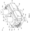
- Figures 2-7 depict schematic views of an illustrative valve assembly 10 for controlling gas flow to a combustion appliance or other similar or different device.
- Figure 2 depicts a schematic perspective view of the illustrative valve assembly 10.
- the gas valve assembly 10 may include a valve body 12, which may generally be a six sided shape or may take on other suitable shapes as desired, and may be formed as a single body or may be multiple pieces connected together.
- the valve body 12 may be a six-sided shape having a first end 12a, a second end 12b, a top 12c, a bottom 12d, a back 12e and a front 12f, as depicted in the various views of Figures 2-3 .
- the terms top, bottom, back, front, left, and right are relative terms used merely to aid in discussing the drawings, and are not meant to be limiting in any manner.
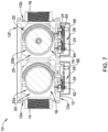
- the illustrative valve body 12 may include an inlet port 14, an outlet port 16 and a fluid path or fluid channel 18 extending between the inlet port 14 and the outlet port 16. Further, the valve body 12 may include one or more gas valve ports 20 (e.g., a first valve port 20a and a second valve port 20b, shown in Figure 7 ) positioned or situated in the fluid channel 18, one or more fuel or gas valve member(s) (sometimes referred to as valve sealing member(s)) moveable within the gas valve ports 20 (e.g., a first valve sealing member within the first valve port 20a and a second valve sealing member within the second valve port 20b, though not explicitly shown), one or more pressure sensor assemblies 24 (e.g., pressure sensors 62, 63, 64, as shown in Figure 7 for example), one or more position sensors (not explicitly shown), and/or one or more valve controllers 26 (as shown in Figure 7 , for example) affixed relative to or coupled to the valve body 12 and/or in electrical communication (e.g., through
- valve assembly 10 may further include one or more actuators for operating moving parts therein.
- valve assembly 10 may have actuators including, but not limited to, one or more stepper motors 94 (shown as extending downward from the bottom 12d of valve body 12 in Figure 2 ), one or more solenoids 96 (shown as extending upward from the top 12c of valve body 12 in Figure 2 ), and one or more servo valves 98 (a servo valve 98 is shown as extending upward from the top 12c of valve body 12 in Figures 2 and 3 , where a second servo valve has been omitted), where the servo valve 98 may be a 3-way auto-servo valve or may be any other type of servo valve.
- the one or more solenoids 96 may control whether the one or more gas valve ports 20 are opened or closed.
- the one or more stepper motors 94 may determine the opening size of the gas valve ports 20 when the corresponding gas valve sealing member is opened by the corresponding solenoid 96. In some cases, the one or more stepper motors 94 may not be provided when, for example, the valve assembly 10 is not a "modulating" valve that allows more than one selectable flow rate to flow through the valve when the valve is opened.
- the one or more actuators and/or motors 94, 96, 98 may be in electrical communication (e.g., through a wired or wireless connection) with the one or more valve controllers 26.
- the valve body 12 may include one or more sensor and electronics compartments 56, which in the illustrative embodiment, extend from the back side 12e as depicted in Figures 2 and 3 .
- the sensor and electronics compartments 56 may be coupled to or may be formed integrally with the valve body 12, and may enclose and/or contain at least a portion of the valve controllers 26, pressure sensor assemblies 24 and/or electronics required for operation of valve assembly 10 as described herein.
- the compartments 56 may be illustratively depicted as separate structures, the compartments 56 may be a single structure part of, extending from, and/or coupled to the valve body 12.
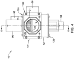
- Figure 4 illustrates the inlet port side of the of the illustrative valve assembly 10 and shows the first end 12a of the valve body 12.
- the valve assembly 10 may include one or more valve sealing members 22 positionable within the fluid channel 18 in response to a force applied by a spring 31.
- the sealing member 22 may be positionable in one or more other suitable manner, as desired.
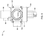
- Figure 5 illustrates the outlet port side of view of the illustrative valve assembly 10 and shows the second end 12b of the valve body 12. Through the valve outlet port 16, the fluid channel 18 may be viewed.
- Figure 6 illustrates a cross-sectional view of the illustrative valve assembly taken at line 6-6 of Figure 4
- Figure 7 illustrates a cross-sectional view of the illustrative valve assembly 10 taken at line 7-7 of Figure 3 .
- the one or more fluid valve ports 20 may include a first gas valve port 20a and a second gas valve port 20b situated along and/or in communication with the fluid channel 18, with an intermediate volume 25 therebetween. This is a double-blocking valve design.
- a corresponding gas valve sealing member 22 (e.g., a first gas valve sealing member 22a in the first gas valve port 20a and a second gas valve sealing member 22b in the second gas valve port 20b, as depicted in Figure 6 ) may be situated in the fluid channel 18 and may be positioned (e.g., concentrically or otherwise) about an axis, rotatable about the axis, longitudinally and axially translatable, rotationally translatable, and/or otherwise selectively movable between a first position (e.g., an opened or closed position) and a second position (e.g., a closed or opened position) within the corresponding valve port 20. Movement of the valve sealing member(s) 22 may open and close the valve port 20.
- valve sealing member 22 may include one or more of a valve disk, a valve stem 92, and/or valve seal for sealing against a valve seat 90 situated in the fluid channel 18, as depicted in Figure 6 , and/or other similar or dissimilar components facilitating a seal.
- valve sealing member 22 may include structural features and/or components of a gate valve, a disk-on-seat valve, a ball valve, a butterfly valve and/or any other type of valve configured to operate from a closed position to an opened position and back to a closed position.
- An open position of a valve sealing member 22 may be any position that allows fluid to flow through the respective gas valve port 20 in which the valve sealing member 22 is situated, and a closed position may be when the valve sealing member 22 forms at least a partial seal at the respective valve port 20.
- the valve sealing member 22 may be operated through any technique.
- the valve sealing member 22 may be operated through utilizing a spring 31, an actuator 29 to effect movement against the spring 31, and, in some cases, a position sensor to sense a position of the valve sealing member 22.
- the valve actuator(s) 29 may be any type of actuator configured to operate the valve sealing member 22 by actuating the valve sealing member 22 from the closed position to an opened position and then back to the closed position during each of a plurality of operation cycles during a lifetime of the gas valve assembly 10 or of the actuator 29.
- the valve actuator 29 may be a solenoid actuator (e.g., a first valve actuator 29a and a second valve actuator 29a), a hydraulic actuator, magnetic actuators, electric motors, pneumatic actuators, and/or other similar or different types of actuators, as desired.
- valve actuators 29a, 29b may be configured to selectively move valves or valve sealing members 22a, 22b of valve ports 20a, 20b between a closed position, which closes the fluid channel 18 between the inlet port 14 and the outlet port 16 of the valve body 12, and an opened position.
- the valve assembly 10 may include a characterized port defined between the inlet port 14 and the outlet port 16.
- a characterized port may be any port (e.g., a fluid valve port 20 or other port or restriction through which the fluid channel 18 may travel) at or across which an analysis may be performed on a fluid flowing therethrough.
- the characterized port may be a port 20 having the valve sealing member 22 configured to be in an opened position and/or in a closed position.
- a characterized port may not correspond to a gas valve port 20 having a valve sealing member 22. Rather, the characterized port may be any constriction or feature across which a pressure drop may be measured and/or a flow rate may be determined.
- the illustrative gas valve assembly 10 of Figures 2-7 is an example of a gas safety shutoff valve, or double-block valve. In some cases, however, it is contemplated that the gas valve assembly 10 may have a single valve sealing member 22, or three or more valve sealing members 22 in series or parallel, as desired.
- the gas valve assembly 10 may include and/or may otherwise be in communication with a flow module 28 (see, for example, the flow module 28 shown as part of the valve controller 26 in Figure 8 ) for sensing one or more parameters of a fluid flowing through fluid channel 18, and in some cases, determining a measure related to a gas flow rate of the fluid flowing through the fluid channel 18.
- the flow module 28 may include a pressure block or pressure sensor assembly (e.g., the pressure sensor assembly 24 discussed herein and/or other suitable pressure sensor assemblies), a temperature sensor, a valve member position sensor, and/or the valve controller 26, among other assemblies, sensors and systems for sensing, monitoring and/or analyzing parameters of a fluid flowing through fluid channel 18.
- the flow module 28 may be a part of the valve controller 26, as shown in Figure 8 , and/or otherwise, may be in communication with the valve controller 26.
- the flow module 28 may utilize any type of sensor to facilitate determining a measure related to a flow rate of a fluid through the fluid channel 18, such as a pressure sensor, a flow sensor, a valve position sensor, and/or other suitable type of sensor, as desired.
- the valve controller 26 may be configured to monitor a differential pressure across a characterized port based on measures from the flow module 28, and in some cases, a position of one or more valve sealing members 22 of the gas valve assembly 10. The information from monitoring may be utilized by the flow module 28 to determine and monitor the flow rate of fluid (e.g., liquid or gas) passing through the fluid channel 18.
- fluid e.g., liquid or gas
- the valve controller 26 may determine a measure that is related to a gas flow rate through the fluid channel 18 based, at least in part, on the measure that is related to the pressure drop across the characterized port along with a pre-stored relationship in the memory 30 between the pressure drop and gas flow rates.
- the memory 30 may be a part of the valve controller 26 and/or more specifically part of the flow module 28, as desired.
- the valve controller 26 may be configured to determine a relationship between a desired burner load or firing rate and the measure related to a gas flow rate based, at least in part, on a previously established relationship stored in the memory 30.
- the previously established relationship may include A/F ratio versus burner load curve and/or A/F ratio look up tables for desired burner loads or firing rates.
- valve controller 26 may be configured to adjust a measure of fuel flow through the valve assembly 10 to achieve a desired A/F ratio.
- the valve controller 26 may be configured to adjust an A/F ratio in real time for received burner load control signals or commands received at the valve assembly 10 in real time based on feedback or measures received from a sensor sensing combustion constituents exiting a combustion chamber of a combustion appliance.
- valve controller 26 may be physically secured or coupled to, or secured or coupled relative to, valve body 12.
- the valve controller 26 may be configured to control and/or monitor a position or state (e.g., an open position and a closed position) of the valve sealing members 22 of the valve ports 20 and/or to perform other functions and analyses, as desired.
- valve controller 26 may be configured to close or open gas valve member(s) or valve sealing member(s) 22 on its own volition, in response to control signals or commands from other systems or appliances (e.g., a system level controller, central building controller, or combustion appliance controller ), and/or in response to received measures related to sensed parameters (e.g., sensed pressures upstream, intermediate, and/or downstream of the characterized valve port(s), sensed differential pressures across the characterized valve port(s), temperature sensed upstream, intermediate, and/or downstream of the characterized valve port(s), sensed combustion constituents in exhaust, and/or in response to other measures, as desired).
- sensed parameters e.g., sensed pressures upstream, intermediate, and/or downstream of the characterized valve port(s), sensed differential pressures across the characterized valve port(s), temperature sensed upstream, intermediate, and/or downstream of the characterized valve port(s), sensed combustion constituents in exhaust, and/or in response to other measures, as desired).
- valve controller 26 may be configured to close or open gas valve member(s) or the valve sealing member(s) 22 in response to determining or receiving a burner load (e.g. firing rate) control signal or command from a system or building level controller or an appliance controller (e.g. burner controller) to control a rate of flow of gas through the valve assembly 10 and to a connected appliance to achieve a desired A/F ratio for the commanded burner load.
- a burner load e.g. firing rate
- appliance controller e.g. burner controller
- the memory 30, which in some cases may be part of valve controller 26, may be configured to record data related to sensed pressures, sensed differential pressures, sensed temperatures, and/or other measures sensed by sensors of the flow module 28 and/or other suitable sensors.
- the valve controller 26 may access this data, and in some cases, communicate (e.g., through a wired or wireless communication link) the data and/or analyses of the data to other systems (e.g., a system level or central building control).
- the memory 30 and/or other memory may be programmed and/or developed to contain software to affect one or more of the configurations described herein.
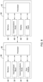
- FIG 8 is a schematic block diagram of an illustrative valve controller 26 in communication with a separate device 40.
- the illustrative valve controller 26 may include a processor or controller 36 (e.g., microcontroller and/or other suitable processor or controller).
- the processor or controller 36 may include or implement a proportional-integral-derivative (PID) controller, but this is not required. Other control configurations are contemplated.
- PID proportional-integral-derivative
- the valve controller 26 may be adapted or configured to operate in accordance with an algorithm that controls or at least partially controls portions of the valve assembly 10.
- the valve controller 26 may include the memory 30 that may be considered as being electrically connected to the processor 36.
- the memory 30 may be used to store any desired information, such as control algorithm, set points, A/F ratio versus burner load firing rate tables or curves, and the like.
- the processor 36 may store information within memory 30 and may subsequently retrieved the stored information.
- the memory 30 may be any suitable type of storage device, such as RAM, ROM, EPROM, a flash drive, a hard drive, and the like.
- the valve controller 26 may include a user interface having display and/or user input features.
- the valve controller 26 may include an input/output block (I/O block) 32 having a number of wire terminals for receiving one or more wires from the valve assembly 10 and/or combustion appliance. While the term I/O may imply both input and output, it is intended to include input only, output only, as well as both input and output.
- the I/O block 32 may be used to communicate one or more signals (e.g., one or more digital signals and/or one or more analog signals) to and/or from the valve assembly 10 and/or combustion appliance.
- the valve controller 26 may have any number of wire terminals for accepting connections from the valve assembly 10 and/or combustion appliance. How many and which of the wire terminals are actually used at a particular installation may depend on the particular configuration of the valve assembly 10 and/or combustion appliance.
- the valve controller 26 may include a communications or data port 34.
- the communications ports 34 may be configured to communicate with the processor 36 and/or the I/O block 32 and may, if desired, be used to upload information to the processor 36, download information from the processor 36, provide commands to the processor 36, send commands from the processor 36, and/or perform any other suitable task.
- the communication port 34 may be a wireless port such as a Bluetooth TM port or any other wireless protocol.
- communication port 34 may be a wired port such as a serial port, a parallel port, a CAT5 port, a USB (universal serial bus) port, or the like.
- the communication port 34 may be a USB port and may be used to download and/or upload information from a USB flash drive.
- Other storage devices may also be employed, as desired, and may be in communication with the processor 36 through the communications port 34.
- the separate device 40 may be in communication with the processor 36 of the valve controller 26 through the communications port 34 or other suitable connection to facilitate calibration procedures and/or programming of the valve controller 26.
- the valve controller 26 may be in wired or wireless communication with the separate device 40.
- the separate device 40 may be a computing device separate from the valve assembly 10.
- the separate device 40 may be a human-machine interface (HMI) such as a personal computer, tablet computer, smart phone, laptop computer, or other suitable computing device as desired.
- HMI human-machine interface
- the separate device 40 may not be a part of the valve assembly 10 or combustion appliance.
- the separate device 40 may be a portable device which travels with the installer.
- the separate device 40 may be adapted or configured to facilitate programming the valve assembly 10 (e.g., generate A/F ratios for a particular valve assembly 10 and each burner rate or firing rate of a combustion appliance) via a set up wizard or software program.
- the separate device 40 may include a processor 42 and memory 44 connected to the processor 42.
- the memory 44 may be used to store any desired information, such as the aforementioned setup wizard, software programs, set points, and the like.
- the processor 42 may store information within memory 44 and may subsequently retrieve the stored information.
- the memory 44 may be any suitable type of storage device, such as RAM, ROM, EPROM, a flash drive, a hard drive, and the like.
- the separate device 40 may include a communications or data port 46.
- the communication ports 46 may be configured to communicate with the processor 42 and may, if desired, be used to either upload information to the processor 42, download information from the processor 42, provide commands to the processor 36, send commands from the processor 36, and/or perform any other suitable task.
- the communications port 46 may be a wireless port such as a Bluetooth TM port or any other wireless protocol.
- communication port 46 may be a wired port such as a serial port, a parallel port, a CAT5 port, a USB (universal serial bus) port, or the like.
- the communication port 46 may be a USB port and may be used to download and/or upload information from a USB flash drive. Other storage devices may also be employed, as desired.
- the separate device 40 may be in communication with the processor 36 of the valve controller 26 to facilitate programming procedures and/or other suitable procedures as desired.
- the separate device 40 may include a display 48.
- the display 48 may be part of a personal computer, tablet computer, smart phone, laptop computer, and/or may include a standalone display.
- the separate device 40 may include a user input 50 for receiving a user input from a user.
- the user input may include a keyboard, mouse, actuatable buttons, a touchscreen display, and/or other user input mechanism. These are just examples.
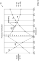
- Figure 9 depicts a graph 80 of illustrative combustion constituents in exhaust from a combustion appliance as a function of excess air in the exhaust.
- the graph depicted in Figure 9 focuses on carbon monoxide (CO) 82, carbon dioxide (CO 2 ) 84, and oxygen (O 2 ) 86.
- CO carbon monoxide
- CO 2 carbon dioxide
- O 2 oxygen
- the slope of the CO 2 84 may indicate whether more or less air is needed in a combustion chamber of the combustion appliance. For example, as shown in Figure 9 , if the slope of the CO 2 84 line is positive, CO 82 is expected to be present and it may be determined more air is needed such that O 2 86 may react with the CO 82 to form CO 2 84. Further, as shown in Figure 9 , if the slope of the CO 2 84 line is negative, it may be determined that the product of combustion does not include an unsafe amount of CO 82.
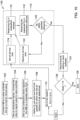
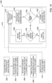
- FIGS 10 and 11 depict flow diagrams of illustrative techniques for programming a valve controller (e.g., the valve controller 26 or other suitable valve controller) to provide predetermined air-fuel ratios in a flow of fluid to a combustion chamber at different burner firing rates (e.g., at different fan speeds).
- a valve controller e.g., the valve controller 26 or other suitable valve controller
- Programming of the valve controller may occur at a time of setting up the valve controller at a burner control system and/or at one or more other suitable times.
- Programming of a valve controller may occur at a site location for a burner control system to account for local pressures, local temperatures, equipment type, and/or other conditions, but this is not required.
- HMI human-machine interface
- HMI 23 or other suitable HMI may be in communication with the valve controller and may be configured to program the valve controller automatically or in response to user input by associating and saving air-fuel ratio set points for specified burner firing rates in the valve controller or in another suitable location in communication with the valve controller.
- valve controller may be configured to program itself automatically, in response to user input, and/or in response to a trigger without the use of an HMI.
- HMI when included, and the valve controller may be referred to as a controller herein even though the HMI and the valve controller may be configured as a single component or separate components.
- the techniques of Figures 10 and 11 may utilize one or more sensors for sensing combustion constituents in an exhaust from the combustion chamber (e.g., the combustion sensor 13 or other suitable sensors) that are in communication with the valve controller.
- the burner control system may include a combustion sensor and in other cases, the burner control system may not include a combustion sensor.
- a combustion sensor may be placed in the exhaust from the combustion chamber and communicatively connected to the valve controller and/or the HMI to provide measurements of the combustion constituents at each burner firing rate and/or each air-fuel ratio.
- each of the techniques may include determining or otherwise establishing an air-fuel ratio setting for a burner firing rate, receiving a measure of one or more combustion constituents exiting the combustion chamber at the air-fuel ratio setting and burner firing rate, determining a difference between the received measure of one or more combustion constituents and a set point for the one or more combustion constituents, adjusting the air-fuel ratio for the burner firing rate until a difference between the received measure of the one or more combustion constituents and the set point for the one or more combustion constituents is below a threshold, and then saving an association between the air-fuel ratio setting that results in received measures below the threshold and the burner firing rate.
- This process may be automatically or otherwise repeated for each of two or more possible burner firing rates. In some cases, the process may be automatically or otherwise repeated for all possible burner firing rates of the combustion appliance.
- Figure 10 depicts an illustrative method 100 of closed loop air-fuel ratio programming based on an amount of oxygen (e.g., a combustion constituent) in the exhaust from the combustion chamber.
- the HMI may be connected 102 to the valve controller and the software of the HMI may proceed to an air-fuel ratio setup.
- the HMI may proceed to the air-fuel ratio setup automatically upon being connected to the valve controller and/or upon receiving user input.
- a combustion sensor may be setup and connected 104 to the HMI and/or the valve controller.
- the combustion sensor may be attached to and/or placed in a flue extending from the combustion chamber and connected to or otherwise placed in communication with the HMI and/or the valve controller.
- the combustion sensor may be configured to sense an oxygen content in the flue
- the combustion sensor may be configured to sense one or more other constituent contents in the flue.
- the combustion sensor may be a single sensor or multiple sensors
- the HMI and/or the valve controller may set up 106 the combustion sensor to ensure it is correctly measuring oxygen.
- the HMI and/or the valve controller may run a calibration procedure to ensure the combustion sensor is properly sensing oxygen.
- one example calibration procedure may compare: (1) a measure of oxygen received from the combustion sensor when air is being blown through the combustion chamber while the combustion appliance is not firing; to (2) an expected oxygen content in air (e.g., 20.95 % oxygen plus or minus a tolerance relative to the other constituents of air) and adjust a sensitivity and/or offset of the sensor, as needed.
- An oxygen set point in exhaust from a combustion chamber at specified burner firing rates for which air-fuel ratios are to be determined may be defined 108.
- the oxygen set point for the exhaust from the combustion chamber may be set by a user when setting up the HMI or valve controller for programming and/or may be pre-determined by an original equipment manufacturer.
- the oxygen set point may be associated with one or more safety regulations as the presence of oxygen in the exhaust may reduce an amount of carbon monoxide in the exhaust from the combustion chamber.
- the burner firing rates for which an air-fuel ratio may be determined may be any set of burner firing rates at which the burner control system may be configured to fire. In some cases, the burner firing rates for which an air-fuel ratio may be determined may be a sub-set of all of the burner firing rates at which the burner control system may be configured to fire. Alternatively, the burner firing rates for which an air-fuel ratio may be determined may be all of the burner firing rates at which the burner controller system may be configured to fire.
- Example burner firing rates may be percentages of a maximum burner firing rate, a fan speed at a percentage of a maximum of burner firing rates, and/or one or more other values related to a burner firing.
- the automated feedback loop 112 may include setting 114 an air-fuel ratio for the burner firing rate;, measuring 116 an oxygen content in exhaust from the combustion chamber with the combustion sensor, and receiving 118 (e.g., via the input/output port 32 or other input/output interface) the measured oxygen in the combustion exhaust.
- the air-fuel ratio setting may be achieved by adjusting a valve position of a gas valve assembly (e.g., the gas valve assembly 10 or other suitable gas valve assembly) to adjust a fuel flow through the gas valve assembly, as the flow of air may be established from the burner firing rate (e.g., a set fan speed may be associated with a burner firing rate).
- a gas valve assembly e.g., the gas valve assembly 10 or other suitable gas valve assembly
- the air-fuel ratio setting may be achieved by adjusting a valve position of a gas valve assembly (e.g., the gas valve assembly 10 or other suitable gas valve assembly) to adjust a fuel flow through the gas valve assembly, as the flow of air may be established from the burner firing rate (e.g., a set fan speed may be associated with a burner firing rate).
- the HMI and/or the valve controller may determine 120 whether the received measured oxygen in the combustion exhaust is within a specified tolerance relative to the defined or set oxygen set point for the exhaust from the combustion chamber.
- An example manner of determining whether the received measured oxygen content in the combustion exhaust is within a tolerance may include determining a difference between the measured oxygen content and the defined oxygen set point and then comparing the determined difference to a threshold value. If the determined difference is below the threshold, it may be determined the measured oxygen content is within a specified tolerance and if the determined difference has reached or gone beyond the threshold, it may be determined the measured oxygen content is not within a specified tolerance.
- the HMI and/or the valve controller may be configured to adjust 122 the air-fuel ratio setting of the burner control system while staying at the specified burner firing rate. Then, steps 114-122 may be repeated at the specified burner firing rate until the measured oxygen content is within the predetermined tolerance. In some cases, the feedback loop 112 may time out and an alarm or other notification may be issued to indicate a measured oxygen content within the predetermined tolerances cannot be achieved at the specified burner firing rate.
- the air-fuel ratio setting may be associated with the burner firing rate and recorded or saved 124 in memory that is in communication with the valve controller.
- the associated air-fuel ratio setting and burner firing rate may be saved in memory of the valve controller or the valve assembly.
- the method 100 may include determining 126 if an air-fuel ratio setting needs to be determined for any other burner firing rates.
- the burner control system may adjust the burner firing rate to the next burner firing rate (e.g., burner firing rate;+i). In some cases, air-fuel ratios may be established for burner firing rates in a sequential manner, but this is not required.
- the method 100 may be ended 128 and the programming of the valve controller may be completed. Once programming is completed, the burner control system may be configured to send a burner firing rate to the valve controller and the valve controller may be configured to adjust a valve of the valve assembly to achieve an air-fuel ratio associated with the received burner firing rate.
- FIG 11 depicts an illustrative method 200 of closed loop air-fuel ratio programming based on an amount of carbon dioxide (e.g., a combustion constituent) in the exhaust from the combustion chamber.
- the HMI may be connected 202 to the valve controller and the software of the HMI may proceed to an air-fuel ratio setup.
- the HMI may proceed to the air-fuel ratio setup automatically upon being connected to the valve controller and/or upon receiving user input.
- a combustion sensor may be setup and connected 204 to the HMI and/or the valve controller.
- the combustion sensor may be attached to and/or placed in a flue extending from the combustion chamber and connected to or otherwise placed in communication with the HMI and/or the valve controller.
- the combustion sensor may be configured to sense a carbon dioxide content in the flue
- the combustion sensor may be configured to sense one or more other constituent contents in the flue.
- the combustion sensor may be a single sensor or multiple sensors
- the HMI and/or the valve controller may set up 206 the combustion sensor to ensure it is correctly measuring carbon dioxide, oxygen, and/or other exhaust constituents.
- the HMI and/or the valve controller may run a calibration procedure to ensure the combustion sensor is properly sensing carbon dioxide, oxygen and/or other exhaust constituents.
- one example calibration procedure may compare: (1) a measure of carbon dioxide, oxygen, and/or other constituents received from the combustion sensor when air is being blown through the combustion chamber while the combustion appliance is not firing: to (2) an expected carbon dioxide, oxygen, and/or other constituent content in air (e.g., 0.04% carbon dioxide and/or 20.95 % oxygen plus or minus a tolerance relative to the other constituents of air) and adjusts a sensitivity and/or offset of the sensor, as needed.
- an expected carbon dioxide, oxygen, and/or other constituent content in air e.g., 0.04% carbon dioxide and/or 20.95 % oxygen plus or minus a tolerance relative to the other constituents of air
- a carbon dioxide set point in exhaust from a combustion chamber at specified burner firing rates for which air-fuel ratios are to be determined may be defined 108.
- the carbon dioxide set point for the exhaust from the combustion chamber may be set by a user when setting up the HMI or valve controller for programming and/or may be pre-determined by an original equipment manufacturer.
- the carbon dioxide set point may be associated with one or more safety regulations as a slope of carbon dioxide content in the exhaust may be indicative of whether carbon monoxide may be present in the exhaust from the combustion chamber.
- the burner firing rates for which an air-fuel ratio may be determined may be any set of burner firing rates at which the burner control system may be configured to fire. In some cases, the burner firing rates for which an air-fuel ratio may be determined may be a sub-set of all of the burner firing rates at which the burner control system may be configured to fire. Alternatively, the burner firing rates for which an air-fuel ratio may be determined may be all of the burner firing rates at which the burner controller system may be configured to fire.
- Example burner firing rates may be percentages of a maximum burner firing rate, a fan speed at a percentage of a maximum of burner firing rate, and/or one or more other values related to a burner firing.
- the HMI or valve controller may determine whether an oxygen content in the combustion exhaust is greater than zero (0) or other threshold. It may be important to determine 214 whether the oxygen content is above zero or other suitable threshold at an air-fuel ratio because if the oxygen content is not greater than zero or other suitable threshold, there may be carbon monoxide present in the exhaust from the combustion chamber.
- the air-fuel ratio may be adjusted 216 by increasing a ratio of air to fuel in the flow of fluid to the combustion chamber and it may be further determined 214 whether an oxygen content in the exhaust from the combustion chamber is greater than zero or other suitable threshold. This process may be repeated until the oxygen content in the exhaust is greater than zero or other suitable threshold.
- an automated feedback loop portion 212 of the method 200 may be initiated at the established burner firing rate.
- the automated feedback loop 212 may include setting 218 an air-fuel ratio for the burner firing rate;, measuring 220 a carbon dioxide content in exhaust from the combustion chamber with the combustion sensor, and receiving 222 (e.g., via the input/output port 32 or other input/output interface) the measured carbon dioxide in the combustion exhaust.
- the air-fuel ratio setting may be achieved by adjusting a valve position of a gas valve assembly (e.g., the gas valve assembly 10 or other suitable gas valve assembly) to adjust a fuel flow through the gas valve assembly, as the flow of air may be established from the burner firing rate (e.g., a set fan speed may be associated with a burner firing rate).
- a gas valve assembly e.g., the gas valve assembly 10 or other suitable gas valve assembly
- the air-fuel ratio setting may be achieved by adjusting a valve position of a gas valve assembly (e.g., the gas valve assembly 10 or other suitable gas valve assembly) to adjust a fuel flow through the gas valve assembly, as the flow of air may be established from the burner firing rate (e.g., a set fan speed may be associated with a burner firing rate).
- the HMI and/or the valve controller may determine 224 whether the received measured carbon dioxide in the combustion exhaust is within a specified tolerance relative to the defined or set carbon dioxide set point for the exhaust from the combustion chamber.
- An example manner of determining whether the received measured carbon dioxide content in the combustion exhaust is within a tolerance may include determining a difference between the measured carbon dioxide content and the defined carbon dioxide set point and then comparing the determined difference to a threshold value. If the determined difference is below the threshold, it may be determined the measured carbon dioxide content is within a specified tolerance and if the determined difference has reached or gone beyond the threshold, it may be determined the measured carbon dioxide content is not within a specified tolerance.
- the HMI and/or the valve controller may be configured to adjust 226 the air-fuel ratio setting of the burner control system while staying at the specified burner firing rate. Then, steps 220-226 may be repeated at the specified burner firing rate until the measured carbon dioxide content is within the predetermined tolerance.
- the feedback loop 212 may time out and an alarm or other notification may be issued to indicate a measured carbon dioxide content within the predetermined tolerances cannot be achieved at the specified burner firing rate.
- the air-fuel ratio setting may be associated with the burner firing rate and recorded or saved 228 in memory that is in communication with the valve controller. In some cases, the associated air-fuel ratio setting and burner firing rate may be saved in memory of the valve controller or the valve assembly, but this is not required.
- the method 200 may include determining 230 if an air-fuel ratio setting needs to be determined for any other burner firing rates.
- the burner control system may adjust the burner firing rate to the next burner firing rate (e.g., burner firing rate i+1 . In some cases, air-fuel ratios may be established for burner firing rates in a sequential manner, but this is not required.
- the method 200 may be ended 232 and the programming of the valve controller may be completed. Once programming is completed, the burner control system may be configured to send a burner firing rate to the valve controller and the valve controller may be configured to adjust a valve of the valve assembly to achieve an air-fuel ratio associated with the received burner firing rate.
- FIGS 12-14 depict flow diagrams of illustrative techniques for controlling a valve controller (e.g., the valve controller 26 or other suitable valve controller) in real-time based on feedback from a combustion sensor (e.g., the combustion sensor 13 or other suitable sensor).
- a combustion sensor e.g., the combustion sensor 13 or other suitable sensor.
- an air-fuel ratio may be adjusted in response to a measurement of a combustion constituent sensed by the combustion sensor.
- Such control of the valve controller may account for local pressures, local temperatures, type of equipment, and/or other conditions, but this is not required.
- At least some of the techniques depicted in Figures 12-14 may be automated using the valve controller and/or one or more other components of a burner control system (e.g., the burner control system 2 or other suitable burner control system). In some cases, the techniques of Figures 12-14 may utilize one or more components in communication with the valve controller.
- a burner control system e.g., the burner control system 2 or other suitable burner control system.
- a human-machine interface (e.g., the HMI 23 or other suitable HMI) may be in communication with the valve controller and configured to interact with the valve controller to automatically control a valve position of a valve assembly (e.g., the gas valve assembly 10 or other suitable valve assembly) to adjust an air-fuel ratio of fluid flowing to a combustion chamber (e.g., the chamber 6 or other chamber) and maintain a measured combustion constituent within a tolerance relative to a set point.
- the HMI when included, and the valve controller may be referred to as a controller herein even though the HMI and the valve controller may be configured as a single component or separate components.
- the techniques of Figures 12-14 may utilize one or more sensors for sensing combustion constituents in an exhaust from the combustion chamber that are in communication with the valve controller.
- the burner control system may include a combustion sensor and in other cases, the burner control system may not include a combustion sensor.
- a combustion sensor may be placed in the exhaust from the combustion chamber and communicatively connected to the valve controller and/or the HMI to provide measurements of the combustion constituents at each burner firing rate and/or each air-fuel ratio.
- each of the techniques may include determining or otherwise establishing an air-fuel ratio setting for a burner firing rate, receiving a measure of one or more combustion constituents exiting the combustion chamber at the air-fuel ratio setting, comparing the received measure of one or more combustion constituents and a set point for the one or more combustion constituents, controlling the air-fuel ratio based at least in part on the comparison between the received measure of one or more combustion constituents and the set point for the one or more combustion constituents.
- Figure 12 depicts an illustrative method 300 of closed loop burner system control to achieve an oxygen (e.g., a combustion constituent) set point in the exhaust from the combustion chamber.
- an HMI When an HMI is to be used in addition to the valve controller, the HMI may be connected 302 to the valve controller and the software of the HMI may proceed to an air-fuel ratio setup. The HMI may proceed to the air-fuel ratio setup automatically upon being connected to the valve controller and/or upon receiving user input.
- a combustion sensor may be setup and connected 304 to the HMI and/or the valve controller.
- the combustion sensor may be attached to and/or placed in a flue extending from the combustion chamber and connected to or otherwise placed in communication with the HMI and/or the valve controller.
- the combustion sensor may be configured to sense an oxygen content in the flue, the combustion sensor may be configured to sense one or more other constituent contents in the flue.
- the combustion sensor may be a single sensor or multiple sensors.
- the HMI and/or the valve controller may set up 306 the combustion sensor to ensure it is correctly measuring oxygen.
- the HMI and/or the valve controller may run a calibration procedure to ensure the combustion sensor is properly sensing oxygen.
- one example calibration procedure may compare: (1) a measure of oxygen received from the combustion sensor when air is being blown through the combustion chamber while the combustion appliance is not firing; to (2) an expected oxygen content in air (e.g., 20.95 % oxygen plus or minus a tolerance relative to the other constituents of air) and adjust a sensitivity and/or offset of the sensor, as needed.
- Such a calibration procedure may be repeated before and/or after each firing in the combustion chamber.
- the calibration procedure may occur upon receiving input from a user and/or at predetermined intervals.
- An oxygen set point and associated tolerances, if any, for oxygen content in exhaust from a combustion chamber may be defined 308.
- the oxygen set point and associated tolerances for oxygen in the exhaust from the combustion chamber may be set by a user when setting up the HMI or valve controller and/or may be pre-determined by an original equipment manufacturer.
- the oxygen set point may be associated with one or more safety regulations as the presence of oxygen in the exhaust may reduce an amount of carbon monoxide in the exhaust from the combustion chamber.
- the oxygen set point may be a constant or may be set to be a function of a burner firing rate (e.g., the set point may be related to a fan speed of the combustion appliance).
- the HMI or valve controller may be configured to automatically change the oxygen set point in response to changes in the burner firing rate (e.g., in response to changes in fan speed of a fan blowing air through the combustion chamber).
- An automated closed-loop control portion 310 of the method 300 may be initiated by igniting 312 a burner of a combustion appliance and the closed-loop control portion 310 may be repeated (e.g., continuously, at predetermined times, etc.) while the burner is firing.
- the burner of the combustion appliance may be ignited at an initial fan speed and air-fuel ratio configured to achieve an oxygen set point for oxygen in the exhaust from the combustion chamber.
- the automated closed loop control portion 310 may include measuring 314 an oxygen content in exhaust from the combustion chamber with the combustion sensor, receiving 316 (e.g., via the input/output port 32 or other input/output interface) the measured oxygen in the combustion exhaust, and determining 318 whether the received measured oxygen in the combustion exhaust is within a specified or predetermined tolerance relative to the oxygen set point for oxygen in the combustion exhaust.
- Determining 318 whether the received measured oxygen in the combustion exhaust is within a specified or predetermined tolerance may include comparing the received measure of oxygen in the combustion exhaust to the oxygen set point for oxygen in the combustion exhaust to determine a difference between the received measure of oxygen and the oxygen set point. Then, when the difference reaches or goes beyond a threshold amount (e.g., is beyond a tolerance), the HMI, valve controller, or other suitable controller of the burner control system may be configured to adjust 320 the air-fuel ratio and the steps 314-320 may be repeated until the received measured oxygen is within the predetermined tolerance.
- a threshold amount e.g., is beyond a tolerance
- the HMI, valve controller, or other suitable controller of the burner control system may be configured to maintain 322 the air-fuel ratio achieving the received measured oxygen and the steps 314-318 and 322 may be repeated until the received measured oxygen reaches or goes beyond the predetermined tolerance.
- a PID controller that implements a PID control algorithm may be utilized to perform the steps of adjusting an air-fuel ratio based on a measured oxygen (e.g., steps 318, 320, and 322) in the closed loop control portion 310 of the method 300.
- the closed loop control portion 310 may output one or more control signals that adjust the air-fuel ratio, where the one or more control signals may include a term that is proportional (P) to a difference between the measured oxygen and an oxygen set point, a term that represents an integral (I) of the difference between the measured oxygen and the oxygen set point, and a term that represents a derivative (D) of the difference between the measured oxygen and the oxygen set point.
- P proportional
- I integral
- D a derivative
- FIG. 13 depicts an illustrative method 400 of closed loop burner system control to achieve a carbon dioxide (e.g., a combustion constituent) set point in the exhaust from the combustion chamber.
- a carbon dioxide e.g., a combustion constituent
- the HMI may be connected 402 to the valve controller and the software of the HMI may proceed to an air-fuel ratio setup.
- the HMI may proceed to the air-fuel ratio setup automatically upon being connected to the valve controller and/or upon receiving user input.
- a combustion sensor may be setup and connected 404 to the HMI and/or the valve controller.
- the combustion sensor may be attached to and/or placed in a flue extending from the combustion chamber and connected to or otherwise placed in communication with the HMI and/or the valve controller.
- the combustion sensor may be configured to sense a carbon dioxide content in the flue
- the combustion sensor may be configured to sense one or more other constituent contents in the flue.
- the combustion sensor may be a single sensor or multiple sensor.
- the HMI and/or the valve controller may set up 406 the combustion sensor to ensure it is correctly measuring oxygen.
- the HMI and/or the valve controller may run a calibration procedure to ensure the combustion sensor is properly sensing carbon dioxide.
- one example calibration procedure may compare: (1) a measure of carbon dioxide received from the combustion sensor when air is being blown through the combustion chamber and when the combustion appliance is not firing; to (2) an expected carbon dioxide content in air (e.g., 0.04 % carbon dioxide plus or minus a tolerance relative to the other constituents of air) and adjust a sensitivity and/or offset of the sensor, as needed.
- Such a calibration procedure may be repeated before and/or after each firing in the combustion chamber.
- the calibration procedure may occur upon receiving input from a user and/or at predetermined intervals.
- a carbon dioxide set point and associated tolerances, if any, for carbon dioxide content in exhaust from a combustion chamber may be defined 408.
- the carbon dioxide set point and associated tolerances for carbon dioxide in the exhaust from the combustion chamber may be set by a user when setting up the HMI or valve controller and/or may be pre-determined by an original equipment manufacturer.
- the carbon dioxide set point may be associated with one or more safety regulations.
- the carbon dioxide set point may be a constant or may be set to be a function of a burner firing rate (e.g., the set point may be related to a fan speed of the combustion appliance).
- the HMI or valve controller may be configured to automatically change the carbon dioxide set point in response to changes in the burner firing rate (e.g., in response to changes in fan speed of a fan blowing air through the combustion chamber).
- An automated closed-loop control portion 410 of the method 400 may be initiated by igniting 412 a burner of a combustion appliance and the closed-loop control portion 410 may be repeated (e.g., continuously, at predetermined times, etc.) while the burner is firing.
- the burner of the combustion appliance may be ignited at an initial fan speed and an air-fuel ratio configured to achieve a carbon dioxide set point for carbon dioxide in the exhaust from the combustion chamber.
- the automated closed loop control portion 410 may include measuring 414 a carbon dioxide content in exhaust from the combustion chamber with the combustion sensor, receiving 416 (e.g., via the input/output port 32 or other input/output interface) the measured carbon dioxide in the combustion exhaust, and determining 418 whether the received measured carbon dioxide in the combustion exhaust is within a specified or predetermined tolerance relative to the carbon dioxide set point for carbon dioxide in the combustion exhaust.
- a slope of the measured carbon dioxide may be indicative of whether carbon monoxide is present in the combustion exhaust. For example, if the slope of the measured carbon dioxide is positive, carbon monoxide may be present in the combustion exhaust and if the slope of the measured carbon monoxide is negative, carbon monoxide likely is not present or is diminishing in the combustion exhaust.
- a slope of carbon monoxide relative to air may be compared 420 to a threshold value (e.g., zero or other suitable threshold value) and if the slope has not reached or gone beyond the threshold, an air-fuel ratio may be increased 422 by increasing a combustion air amount (e.g., increasing a fan speed) and/or by decreasing fuel (e.g., by closing a valve or reducing a valve opening) to a combustion chamber.
- a threshold value e.g., zero or other suitable threshold value
- Determining 418 whether the received measured carbon dioxide in the combustion exhaust is within a specified or predetermined tolerance may include comparing the received measure of carbon dioxide in the combustion exhaust to the carbon dioxide set point for carbon dioxide in the combustion exhaust to determine a difference between the received measure of carbon dioxide and the carbon dioxide set point. Then, when the difference reaches or goes beyond a threshold amount (e.g., is beyond a tolerance), the HMI, valve controller, or other suitable controller of the burner control system may be configured to adjust 424 the air-fuel ratio and the steps 414-424 may be repeated until the received measured carbon dioxide is within the predetermined tolerance.
- a threshold amount e.g., is beyond a tolerance
- the HMI, valve controller, or other suitable controller of the burner control system may be configured to maintain 426 the air-fuel ratio achieving the received measured carbon dioxide and the steps 414-422 and 426 may be repeated until the received measured carbon dioxide reaches or goes beyond the predetermined tolerance.
- a proportional-integral-derivative (PID) controller that implements a PID control algorithm may be utilized to perform the steps of adjusting an air-fuel ratio based on a measured carbon dioxide (e.g., steps 418, 424, and 426) in the closed loop control portion 410 of the method 400.
- PID proportional-integral-derivative
- the closed loop control portion 410 may output one or more control signals that adjust the air-fuel ratio, where the one or more control signals may include a term that is proportional (P) to a difference between the measured carbon dioxide and a carbon dioxide set point, a term that represents an integral of the difference between the measured carbon dioxide and the carbon dioxide set point, and a term that represents a derivative of the difference between the measured carbon dioxide and the carbon dioxide set point.
- P proportional
- FIG 14 depicts an illustrative method 500 of closed loop burner system control to achieve a carbon dioxide (e.g., a combustion constituent) set point in the exhaust from the combustion chamber based on sensed carbon dioxide and sensed oxygen.
- a carbon dioxide e.g., a combustion constituent
- the HMI may be connected 502 to the valve controller and the software of the HMI may proceed to an air-fuel ratio setup.
- the HMI may proceed to the air-fuel ratio setup automatically upon being connected to the valve controller and/or upon receiving user input.
- a combustion sensor may be setup and connected 504 to the HMI and/or the valve controller.
- the combustion sensor may be attached to and/or placed in a flue extending from the combustion chamber and connected to or otherwise placed in communication with the HMI and/or the valve controller.
- the combustion sensor may be configured to sense a carbon dioxide and oxygen content in the flue, the combustion sensor may be configured to sense one or more other constituent contents in the flue.
- the combustion sensor may be a single sensor or more multiple sensors.
- the combustion sensor may be a single sensor or multiple sensors.
- the HMI and/or the valve controller may set up 506 the combustion sensor to ensure it is correctly measuring oxygen.
- the HMI and/or the valve controller may run a calibration procedure to ensure the combustion sensor is properly sensing carbon dioxide and oxygen.
- one example calibration procedure may compare: (1) a measure of carbon dioxide and a measure of oxygen both received from the combustion sensor when air is being blown through the combustion chamber while the combustion appliance is not firing; to (2) an expected carbon dioxide content in air and an expected oxygen content in air (e.g., 0.04 % carbon dioxide plus or minus a tolerance relative to the other constituents of air and 20.95 % oxygen plus or minus a tolerance relative to the other constituents of air) and adjust a sensitivity and/or an offset of the sensor, as needed.
- Such a calibration procedure may be repeated before and/or after each firing in the combustion chamber.
- the calibration procedure may occur upon receiving input from a user and/or at predetermined intervals.
- a carbon dioxide set point and associated tolerances, if any, for combustion constituents in the exhaust from a combustion chamber may be defined 508.
- the carbon dioxide set point and associated tolerances for combustion constituents in the exhaust from the combustion chamber may be set by a user when setting up the HMI or valve controller and/or may be pre-determined by an original equipment manufacturer.
- the carbon dioxide set point may be associated with one or more safety regulations.
- the carbon dioxide set point may be a constant or may be set to be a function of a burner firing rate (e.g., the set point may be related to a fan speed of the combustion appliance).
- the HMI or valve controller may be configured to automatically change the carbon dioxide set point in response to changes in the burner firing rate (e.g., in response to changes in fan speed of a fan blowing air through the combustion chamber).
- An automated closed-loop control portion 510 of the method 500 may be initiated by igniting 512 a burner of a combustion appliance and the closed-loop control portion 510 may be repeated (e.g., continuously, at predetermined times, etc.) while the burner is firing.
- the burner of the combustion appliance may be ignited at an initial fan speed and an air-fuel ratio configured to achieve a carbon dioxide set point for carbon dioxide in the exhaust from the combustion chamber.
- the automated closed loop control portion 510 may include measuring 514 a carbon dioxide content in exhaust from the combustion chamber with the combustion sensor, receiving 516 (e.g., via the input/output port 32 or other input/output interface) the measured carbon dioxide in the combustion exhaust, and determining 518 whether the received measured carbon dioxide in the combustion exhaust is within a specified or predetermined tolerance relative to the carbon dioxide set point for carbon dioxide in the combustion exhaust.
- the HMI or valve controller may be configured to determine 520 whether an oxygen content in the combustion exhaust is greater than zero (0) or other suitable threshold. If the oxygen content of the exhaust is not above zero or other suitable threshold, the air-fuel ratio may be adjusted 522 by increasing a ratio of air to fuel in the flow of fluid to the combustion chamber via increasing a combustion air amount (e.g., increasing a fan speed) and/or by decreasing fuel (e.g., by closing a valve or reducing a valve opening) to a combustion chamber and it may be further determined 520 whether an oxygen content in the exhaust from the combustion chamber is greater than zero or other suitable threshold.
- a combustion air amount e.g., increasing a fan speed
- decreasing fuel e.g., by closing a valve or reducing a valve opening
- This process may be repeated until the oxygen content in the exhaust is greater than zero or other suitable threshold. Once the oxygen content of the exhaust has been determined to exceed zero or go beyond one or more other suitable thresholds, it may be determined 518 whether the received measure of carbon dioxide is within the predetermined tolerance.
- Determining 518 whether the received measured carbon dioxide in the combustion exhaust is within a specified or predetermined tolerance may include comparing the received measure of carbon dioxide in the combustion exhaust to the carbon dioxide set point for carbon dioxide in the combustion exhaust to determine a difference between the received measure of carbon dioxide and the carbon dioxide set point. Then, when the difference reaches or goes beyond a threshold amount (e.g., is beyond a tolerance), the HMI, valve controller, or other suitable controller of the burner control system may be configured to adjust 524 the air-fuel ratio and the steps 514-524 may be repeated until the received measured carbon dioxide is within the predetermined tolerance.
- a threshold amount e.g., is beyond a tolerance
- the HMI, valve controller, or other suitable controller of the burner control system may be configured to maintain 526 the air-fuel ratio achieving the received measured oxygen and the steps 514-522 and 526 may be repeated until the received measured oxygen reaches or goes beyond the predetermined tolerance.
- a proportional-integral-derivative (PID) controller that implements a PID control algorithm may be utilized to perform the steps of adjusting an air-fuel ratio based on a measured carbon dioxide (e.g., steps 518, 524, and 526) in the closed loop control portion 510 of the method 500.
- PID proportional-integral-derivative
- the closed loop control portion 510 may output one or more control signals that adjust the air-fuel ratio, where the one or more control signals include a term that is proportional to a difference between the measured carbon dioxide and a carbon dioxide set point, a term that is related to an integral of the difference between the measured carbon dioxide and the carbon dioxide set point, and a term that is related to a derivative of the difference between the measured carbon dioxide and the carbon dioxide set point.
Landscapes
- Engineering & Computer Science (AREA)
- Chemical & Material Sciences (AREA)
- Combustion & Propulsion (AREA)
- Mechanical Engineering (AREA)
- General Engineering & Computer Science (AREA)
- Physics & Mathematics (AREA)
- General Physics & Mathematics (AREA)
- Automation & Control Theory (AREA)
- Regulation And Control Of Combustion (AREA)
Abstract
Description
- This application claims the benefit of priority of co-pending
U.S. Provisional Application Serial No. 62/612,250, filed December 29, 2017 - The present disclosure relates generally to systems and methods for defining an air/fuel ratio for a burner of a combustion appliance, and more particularly to programming a controller of a valve assembly and controlling operation of a combustion appliance based on defined air-fuel ratios.
- The air/fuel ratio used during the operation of a combustion appliance can affect the efficiency and emissions of the combustion appliance. Examples of such combustion appliances include furnaces, water heaters, boilers, direct/in-direct make-up air heaters, power/jet burners and any other residential, commercial or industrial combustion appliance. In many cases, a combustion appliance can be modulated over a plurality of burner loads, with each burner load resulting in a different heat output. At higher burner loads, more fuel and more air are provided to the burner, and at lower burner loads less fuel and less air are provided to the burner.
- In many cases, the combustion appliance may include a burner that is fed air by a modulating blower or the like and fuel is fed by a modulating gas valve. The modulating gas valve may have an air/fuel controller that is designed to control the air/fuel ratio that is delivered to the burner. In some cases, the air/fuel controller may not have direct control over the burner load of the combustion appliance. In other cases, the air/fuel controller may be a slave device and simply receive a burner load command from an external controller, and may respond by modulating the gas valve to provide a desired air/fuel ratio to the burner at the commanded burner load. In some instances, the modulating the gas valve may be pneumatically controlled. In other instances, the modulating the gas valve may be controlled by an electronically controlled actuator.
- In many cases, an air/fuel ratio versus burner load curve is set during a commissioning process of the gas valve at the time of installation or during subsequent maintenance. The particular air/fuel ratio versus burner load curve may depend on the particular equipment involved and/or the particular application at hand. Commissioning the air/fuel ratio versus burner load can be a time consuming and tedious process.
- The present disclosure relates generally to systems and methods for defining an air/fuel ratio for a burner of a combustion appliance, and more particularly to programming a controller of a valve assembly. The present disclosure also relates to controlling operation of a burner of a combustion appliance based on defined air-fuel ratios.
- In one example of the disclosure, an auto-programming control system for a combustion burner having a plurality of burner firing rates is disclosed. The auto-programming control system may include a controller, and memory in communication with the controller. The controller may be configured to control an air-fuel ratio of a fluid flow to a combustion chamber. The controller may be configured to fire the combustion burner at each of the plurality of burner firing rates, and at each of the plurality of burner firing rates the controller may be configured to set an air-fuel setting, receive a measure of a combustion constituent exiting the combustion chamber at the air-fuel setting, determine a difference between the measure of the combustion constituent exiting the combustion chamber and a set point at the air-fuel setting, adjust the air-fuel setting until the difference between the measure of the combustion constituent exiting the combustion chamber and the set point is below a threshold, and save an association between the air-fuel setting and the corresponding one of the plurality of burner firing rates to the memory, and then move to a next burner firing rate of the plurality of burner firing rates and repeat.
- In another example of the disclosure, a closed loop control system may include a controller and an input/output port in communication with the controller. The controller may be configured to control an air-fuel ratio of a fluid flow to a combustion chamber. The controller may be further configured to receive via the input/output port a measure of a combustion constituent exiting the combustion chamber, compare the measure of the combustion constituent exiting the combustion chamber to a set point, and control the air-fuel ratio in the fluid flow to the combustion chamber based at least in part on the comparison of the measure of the combustion constituent exiting the combustion chamber to the set point.
- The preceding summary is provided to facilitate an understanding of some of the innovative features unique to the present disclosure and is not intended to be a full description. A full appreciation of the disclosure can be gained by taking the entire specification, claims, drawings, and abstract as a whole.
- The disclosure may be more completely understood in consideration of the following description of various illustrative embodiments in connection with the accompanying drawings, in which:
-
Figure 1 is a schematic diagram of an illustrative burner control system; -
Figure 2 is a schematic perspective view of an illustrative gas valve assembly; -
Figure 3 is a schematic side view of the illustrative gas valve assembly ofFigure 2 ; -
Figure 4 is a schematic side of the inlet port side of the illustrative gas valve assembly ofFigure 2 ; -
Figure 5 is a schematic side view of the outlet port side of the illustrative gas valve assembly ofFigure 2 ; -
Figure 6 is a schematic cross-sectional view of the illustrative gas valve assembly ofFigure 2 , taken along line 6-6 ofFigure 4 ; -
Figure 7 is a cross-sectional view of the illustrative gas valve assembly ofFigure 2 , taken along line 7-7 ofFigure 3 ; -
Figure 8 is a schematic block diagram of an illustrative valve controller in communication with an illustrative external device; -
Figure 9 is a graph of illustrative combustion constituents in exhaust of a combustion reaction; -
Figure 10 is a schematic flow diagram depicting an illustrative air-fuel ratio programming procedure based on oxygen content in an exhaust from a combustion appliance; -
Figure 11 is a schematic flow diagram depicting an illustrative air-fuel ratio programming procedure based on carbon dioxide content in an exhaust from a combustion appliance; -
Figure 12 is a schematic flow diagram depicting an illustrative closed-loop air-fuel ratio control procedure for a combustion appliance based on oxygen content in an exhaust from a combustion appliance; -
Figure 13 is a schematic flow diagram depicting an illustrative closed-loop air-fuel ratio control procedure for a combustion appliance based on carbon dioxide content in an exhaust from a combustion appliance; and -
Figure 14 is a schematic flow diagram depicting an illustrative closed-loop air-fuel ratio control procedure for a combustion appliance based on oxygen and carbon dioxide content in an exhaust from a combustion appliance. - While the disclosure is amenable to various modifications and alternative forms, specifics thereof have been shown by way of example in the drawings and will be described in detail. It should be understood, however, that the intention is not to limit aspects of the disclosure to the particular illustrative embodiments described. On the contrary, the intention is to cover all modifications, equivalents, and alternatives falling within the spirit and scope of the disclosure.
- The following description should be read with reference to the drawings wherein like reference numerals indicate like elements throughout the several views. The detailed description and drawings show several illustrative embodiments which are meant to be illustrative of the claimed disclosure.
- Valves may be added to fluid supply lines including, but not limited to, gas valves added to supply lines configured to provide fuel to a burner of a combustion appliance. In some cases, an air to fuel ratio (also referred to as air/fuel ratio, air-fuel ratio, or A/F ratio) may depend on or may be proportional to a burner load of the combustion appliance. The A/F ratio may affect the burner efficiency and/or burner emissions differently at different burner loads (i.e. burner firing rates). In heating (and/or other fuel burning) applications, adjustments to an air/fuel ratio in real time based on sensor feedback and/or based on a burner load or firing rate may be used to achieve set points for combustion constituents (e.g., CO2, O2, CO, etc.) exiting a combustion chamber over an entire burner load or burner firing rate range of the system.
- In some cases, a gas valve assembly may be configured to monitor and/or control various operations including, but not limited to, gas flow and/or gas consumption, electronic cycle counting, overpressure diagnostics, high gas pressure and low gas pressure detection, valve proving system tests, valve leakage tests, proof of valve closure tests, diagnostic communications, and/or any other suitable operation as desired. In addition, a gas valve assembly may be configured to facilitate adjusting A/F ratio in real or near real time based on sensor feedback and/or based on a burner load or firing rate, as further described below.
-
Figure 1 is schematic diagram of aburner control system 2 having a fuel and air mixture where an air/fuel ratio is adjustable. Theburner control system 2 may have anair supply channel 3 for supplyingair 4 into a chamber 6 (e.g., a combustion chamber or other suitable chamber) with afan 5 at one end of thechannel 3. At the other end ofchannel 3, the suppliedair 4 may enter thechamber 6. Fuel 7 (e.g., gas or other suitable fuel) may be injected, via afuel channel 8, into the airflow at a location in theair supply channel 3 and/or in thechamber 6. Thefuel channel 8 may be connected to agas valve assembly 10 and in communication with theair supply channel 3 and/or thechamber 6. Theburner control system 2 depicted inFigure 1 is only an illustrative schematic depiction and it is contemplated theburner control system 2 may have one or more additional or alternative components and/or configurations. - A
valve controller 26 may be in communication with thevalve assembly 10 or may be part of thevalve assembly 10, as discussed in greater detail below. In some cases, thevalve controller 26 may provide asignal 9 to thevalve assembly 10 to adjust a position of a valve of thevalve assembly 10. In some cases, thevalve assembly 10 may be motorized and may be configured to open and/or close the valve thereof incrementally according to thesignal 9. For example, thevalve controller 26 may send thesignal 9 to thevalve assembly 10 to open the valve when more fuel is needed and may send thesignal 9 to thevalve assembly 10 to close the valve when less fuel is needed. - In some cases, the
valve controller 26 may be connected to thefan 5, which may be varied in speed according to asignal 11 from thevalve controller 26 to vary a flow ofair 4 through theair supply channel 3 and establish a burner load or firing rate. Alternatively or additionally, thefan 5 may be configured to receive a control signal to vary a flow ofair 4 through theair supply channel 3 from a burner controller, combustion appliance controller, or other controller separate from thevalve controller 26 to facilitate establishing the burner load or firing rate. In such cases, thevalve controller 26 may also be configured to receive a control signal indicating a set speed of thefan 5 from the burner controller, combustion appliance controller, or other controller separate from thevalve controller 26. Changing speeds of thefan 5 may increase or decrease the burner load or firing rate of the burner or combustion appliance, as the burner load or firing rate may be or may be a function of the speed of the fan. - An air/fuel ratio of the
burner control system 2 may be controlled to achieve a desired measure of combustion constituents exiting thechamber 6. In some cases, acombustion sensor 13 may be mounted at anexhaust port 15 of thechamber 6 to provide a signal 17 (e.g., via a wired or wireless communication path) to thevalve controller 26, where thecombustion sensor 13 may indicate a measure and/or other information ofcombustion constituents 19 emanating from aflame 21. In some cases, thecombustion sensor 13 may be utilized during setup and/or at other times to program thevalve controller 26 to include a table of air/fuel ratios for one or more burner loads or firing rates of the combustion appliance that are configured to achieve set points for measures of thecombustion constituents 19 in the exhaust from thechamber 6. In such cases, thecombustion sensor 13 may be removable and may be utilized only for programming and setting up thevalve controller 26, but this is not required. Alternatively or in addition, thecombustion sensor 13 may be permanently mounted or otherwise mounted at theexhaust port 15 of thechamber 6 and thesignal 17 from thecombustion sensor 13 may be used to provide a closed loop control of the air/fuel ratio of fluid flow to thechamber 6 based on thesignal 17. - A separate device 40 (e.g., a human-machine-interface (HMI)) may be utilized to facilitate setting up and/or programming the
valve controller 26 in the manners described herein and/or in one or more other suitable manners. As shown inFigure 1 , theseparate device 40 may be in communication with thevalve controller 26. Alternatively, theseparate device 40 may be omitted and thevalve controller 26 and/or one or more other suitable controllers of the combustion appliance may be configured to facilitate setting up and/or programming thevalve controller 26. -
Figures 2-7 depict schematic views of anillustrative valve assembly 10 for controlling gas flow to a combustion appliance or other similar or different device.Figure 2 depicts a schematic perspective view of theillustrative valve assembly 10. In the illustrative embodiment, thegas valve assembly 10 may include avalve body 12, which may generally be a six sided shape or may take on other suitable shapes as desired, and may be formed as a single body or may be multiple pieces connected together. As shown, thevalve body 12 may be a six-sided shape having afirst end 12a, asecond end 12b, a top 12c, abottom 12d, aback 12e and a front 12f, as depicted in the various views ofFigures 2-3 . The terms top, bottom, back, front, left, and right are relative terms used merely to aid in discussing the drawings, and are not meant to be limiting in any manner. - The
illustrative valve body 12 may include aninlet port 14, anoutlet port 16 and a fluid path orfluid channel 18 extending between theinlet port 14 and theoutlet port 16. Further, thevalve body 12 may include one or more gas valve ports 20 (e.g., afirst valve port 20a and asecond valve port 20b, shown inFigure 7 ) positioned or situated in thefluid channel 18, one or more fuel or gas valve member(s) (sometimes referred to as valve sealing member(s)) moveable within the gas valve ports 20 (e.g., a first valve sealing member within thefirst valve port 20a and a second valve sealing member within thesecond valve port 20b, though not explicitly shown), one or more pressure sensor assemblies 24 (e.g.,pressure sensors Figure 7 for example), one or more position sensors (not explicitly shown), and/or one or more valve controllers 26 (as shown inFigure 7 , for example) affixed relative to or coupled to thevalve body 12 and/or in electrical communication (e.g., through a wired or wireless connection) withpressure sensor assemblies 24, position sensor(s), and/or gas valve members. - The
valve assembly 10 may further include one or more actuators for operating moving parts therein. For example,valve assembly 10 may have actuators including, but not limited to, one or more stepper motors 94 (shown as extending downward from the bottom 12d ofvalve body 12 inFigure 2 ), one or more solenoids 96 (shown as extending upward from the top 12c ofvalve body 12 inFigure 2 ), and one or more servo valves 98 (aservo valve 98 is shown as extending upward from the top 12c ofvalve body 12 inFigures 2 and3 , where a second servo valve has been omitted), where theservo valve 98 may be a 3-way auto-servo valve or may be any other type of servo valve. In one illustrative embodiment, the one ormore solenoids 96 may control whether the one or moregas valve ports 20 are opened or closed. The one ormore stepper motors 94 may determine the opening size of thegas valve ports 20 when the corresponding gas valve sealing member is opened by the correspondingsolenoid 96. In some cases, the one ormore stepper motors 94 may not be provided when, for example, thevalve assembly 10 is not a "modulating" valve that allows more than one selectable flow rate to flow through the valve when the valve is opened. The one or more actuators and/ormotors more valve controllers 26. - As shown, the
valve body 12 may include one or more sensor and electronics compartments 56, which in the illustrative embodiment, extend from theback side 12e as depicted inFigures 2 and3 . The sensor and electronics compartments 56 may be coupled to or may be formed integrally with thevalve body 12, and may enclose and/or contain at least a portion of thevalve controllers 26,pressure sensor assemblies 24 and/or electronics required for operation ofvalve assembly 10 as described herein. Although thecompartments 56 may be illustratively depicted as separate structures, thecompartments 56 may be a single structure part of, extending from, and/or coupled to thevalve body 12. -
Figure 4 illustrates the inlet port side of the of theillustrative valve assembly 10 and shows thefirst end 12a of thevalve body 12. Through thevalve inlet port 14, it can be seen fromFigure 4 that thevalve assembly 10 may include one or morevalve sealing members 22 positionable within thefluid channel 18 in response to a force applied by aspring 31. The sealingmember 22 may be positionable in one or more other suitable manner, as desired. -
Figure 5 illustrates the outlet port side of view of theillustrative valve assembly 10 and shows thesecond end 12b of thevalve body 12. Through thevalve outlet port 16, thefluid channel 18 may be viewed.Figure 6 illustrates a cross-sectional view of the illustrative valve assembly taken at line 6-6 ofFigure 4 , andFigure 7 illustrates a cross-sectional view of theillustrative valve assembly 10 taken at line 7-7 ofFigure 3 . In the illustrative embodiment, the one or morefluid valve ports 20 may include a firstgas valve port 20a and a secondgas valve port 20b situated along and/or in communication with thefluid channel 18, with anintermediate volume 25 therebetween. This is a double-blocking valve design. Within eachgas valve port 20, a corresponding gas valve sealing member 22 (e.g., a first gasvalve sealing member 22a in the firstgas valve port 20a and a second gasvalve sealing member 22b in the secondgas valve port 20b, as depicted inFigure 6 ) may be situated in thefluid channel 18 and may be positioned (e.g., concentrically or otherwise) about an axis, rotatable about the axis, longitudinally and axially translatable, rotationally translatable, and/or otherwise selectively movable between a first position (e.g., an opened or closed position) and a second position (e.g., a closed or opened position) within the correspondingvalve port 20. Movement of the valve sealing member(s) 22 may open and close thevalve port 20. - It is contemplated that the
valve sealing member 22 may include one or more of a valve disk, avalve stem 92, and/or valve seal for sealing against avalve seat 90 situated in thefluid channel 18, as depicted inFigure 6 , and/or other similar or dissimilar components facilitating a seal. Alternatively, or in addition, thevalve sealing member 22 may include structural features and/or components of a gate valve, a disk-on-seat valve, a ball valve, a butterfly valve and/or any other type of valve configured to operate from a closed position to an opened position and back to a closed position. An open position of avalve sealing member 22 may be any position that allows fluid to flow through the respectivegas valve port 20 in which thevalve sealing member 22 is situated, and a closed position may be when thevalve sealing member 22 forms at least a partial seal at therespective valve port 20. Thevalve sealing member 22 may be operated through any technique. For example, thevalve sealing member 22 may be operated through utilizing aspring 31, anactuator 29 to effect movement against thespring 31, and, in some cases, a position sensor to sense a position of thevalve sealing member 22. - The valve actuator(s) 29 may be any type of actuator configured to operate the
valve sealing member 22 by actuating thevalve sealing member 22 from the closed position to an opened position and then back to the closed position during each of a plurality of operation cycles during a lifetime of thegas valve assembly 10 or of theactuator 29. In some cases, thevalve actuator 29 may be a solenoid actuator (e.g., afirst valve actuator 29a and asecond valve actuator 29a), a hydraulic actuator, magnetic actuators, electric motors, pneumatic actuators, and/or other similar or different types of actuators, as desired. In the example shown inFigure 6 ,valve actuators valve sealing members valve ports fluid channel 18 between theinlet port 14 and theoutlet port 16 of thevalve body 12, and an opened position. - The
valve assembly 10 may include a characterized port defined between theinlet port 14 and theoutlet port 16. A characterized port may be any port (e.g., afluid valve port 20 or other port or restriction through which thefluid channel 18 may travel) at or across which an analysis may be performed on a fluid flowing therethrough. For example, if a flow resistance of avalve port 20 is known over a range of travel of thevalve sealing member 22, the one of the one or moregas valve ports 20 may be considered the characterized port. As such, and in some cases, the characterized port may be aport 20 having thevalve sealing member 22 configured to be in an opened position and/or in a closed position. Alternatively, or in addition, a characterized port may not correspond to agas valve port 20 having avalve sealing member 22. Rather, the characterized port may be any constriction or feature across which a pressure drop may be measured and/or a flow rate may be determined. - The illustrative
gas valve assembly 10 ofFigures 2-7 is an example of a gas safety shutoff valve, or double-block valve. In some cases, however, it is contemplated that thegas valve assembly 10 may have a singlevalve sealing member 22, or three or morevalve sealing members 22 in series or parallel, as desired. - The
gas valve assembly 10 may include and/or may otherwise be in communication with a flow module 28 (see, for example, theflow module 28 shown as part of thevalve controller 26 inFigure 8 ) for sensing one or more parameters of a fluid flowing throughfluid channel 18, and in some cases, determining a measure related to a gas flow rate of the fluid flowing through thefluid channel 18. In some instances, theflow module 28 may include a pressure block or pressure sensor assembly (e.g., thepressure sensor assembly 24 discussed herein and/or other suitable pressure sensor assemblies), a temperature sensor, a valve member position sensor, and/or thevalve controller 26, among other assemblies, sensors and systems for sensing, monitoring and/or analyzing parameters of a fluid flowing throughfluid channel 18. Theflow module 28 may be a part of thevalve controller 26, as shown inFigure 8 , and/or otherwise, may be in communication with thevalve controller 26. - It is contemplated that the
flow module 28 may utilize any type of sensor to facilitate determining a measure related to a flow rate of a fluid through thefluid channel 18, such as a pressure sensor, a flow sensor, a valve position sensor, and/or other suitable type of sensor, as desired. In one example, thevalve controller 26 may be configured to monitor a differential pressure across a characterized port based on measures from theflow module 28, and in some cases, a position of one or morevalve sealing members 22 of thegas valve assembly 10. The information from monitoring may be utilized by theflow module 28 to determine and monitor the flow rate of fluid (e.g., liquid or gas) passing through thefluid channel 18. In some cases, thevalve controller 26 may determine a measure that is related to a gas flow rate through thefluid channel 18 based, at least in part, on the measure that is related to the pressure drop across the characterized port along with a pre-stored relationship in thememory 30 between the pressure drop and gas flow rates. Thememory 30 may be a part of thevalve controller 26 and/or more specifically part of theflow module 28, as desired. - The
valve controller 26 may be configured to determine a relationship between a desired burner load or firing rate and the measure related to a gas flow rate based, at least in part, on a previously established relationship stored in thememory 30. In some cases, the previously established relationship may include A/F ratio versus burner load curve and/or A/F ratio look up tables for desired burner loads or firing rates. - The different relationships described herein may be generated during installation and/or calibration of the
valve assembly 10, and may be stored as data tables or curves in thememory 30. Using the previously established relationship(s) between flow rate and burner load or firing rate and a burner load control signal or command received at thevalve assembly 10 from another device (e.g. building controller, system level controller or combustion appliance controller) within the system, thevalve controller 26 may be configured to adjust a measure of fuel flow through thevalve assembly 10 to achieve a desired A/F ratio. Alternatively or in addition, thevalve controller 26 may be configured to adjust an A/F ratio in real time for received burner load control signals or commands received at thevalve assembly 10 in real time based on feedback or measures received from a sensor sensing combustion constituents exiting a combustion chamber of a combustion appliance. - It is contemplated that the valve controller 26 (see,
Figure 7 ) may be physically secured or coupled to, or secured or coupled relative to,valve body 12. Thevalve controller 26 may be configured to control and/or monitor a position or state (e.g., an open position and a closed position) of thevalve sealing members 22 of thevalve ports 20 and/or to perform other functions and analyses, as desired. In some cases, thevalve controller 26 may be configured to close or open gas valve member(s) or valve sealing member(s) 22 on its own volition, in response to control signals or commands from other systems or appliances (e.g., a system level controller, central building controller, or combustion appliance controller ), and/or in response to received measures related to sensed parameters (e.g., sensed pressures upstream, intermediate, and/or downstream of the characterized valve port(s), sensed differential pressures across the characterized valve port(s), temperature sensed upstream, intermediate, and/or downstream of the characterized valve port(s), sensed combustion constituents in exhaust, and/or in response to other measures, as desired). In one example, thevalve controller 26 may be configured to close or open gas valve member(s) or the valve sealing member(s) 22 in response to determining or receiving a burner load (e.g. firing rate) control signal or command from a system or building level controller or an appliance controller (e.g. burner controller) to control a rate of flow of gas through thevalve assembly 10 and to a connected appliance to achieve a desired A/F ratio for the commanded burner load. - The
memory 30, which in some cases may be part ofvalve controller 26, may be configured to record data related to sensed pressures, sensed differential pressures, sensed temperatures, and/or other measures sensed by sensors of theflow module 28 and/or other suitable sensors. Thevalve controller 26 may access this data, and in some cases, communicate (e.g., through a wired or wireless communication link) the data and/or analyses of the data to other systems (e.g., a system level or central building control). Thememory 30 and/or other memory may be programmed and/or developed to contain software to affect one or more of the configurations described herein. -
Figure 8 is a schematic block diagram of anillustrative valve controller 26 in communication with aseparate device 40. Theillustrative valve controller 26 may include a processor or controller 36 (e.g., microcontroller and/or other suitable processor or controller). The processor orcontroller 36 may include or implement a proportional-integral-derivative (PID) controller, but this is not required. Other control configurations are contemplated. Thevalve controller 26 may be adapted or configured to operate in accordance with an algorithm that controls or at least partially controls portions of thevalve assembly 10. Thevalve controller 26 may include thememory 30 that may be considered as being electrically connected to theprocessor 36. Thememory 30 may be used to store any desired information, such as control algorithm, set points, A/F ratio versus burner load firing rate tables or curves, and the like. Theprocessor 36 may store information withinmemory 30 and may subsequently retrieved the stored information. Thememory 30 may be any suitable type of storage device, such as RAM, ROM, EPROM, a flash drive, a hard drive, and the like. Further, although not depicted inFigure 8 , thevalve controller 26 may include a user interface having display and/or user input features. - The
valve controller 26 may include an input/output block (I/O block) 32 having a number of wire terminals for receiving one or more wires from thevalve assembly 10 and/or combustion appliance. While the term I/O may imply both input and output, it is intended to include input only, output only, as well as both input and output. The I/O block 32 may be used to communicate one or more signals (e.g., one or more digital signals and/or one or more analog signals) to and/or from thevalve assembly 10 and/or combustion appliance. Thevalve controller 26 may have any number of wire terminals for accepting connections from thevalve assembly 10 and/or combustion appliance. How many and which of the wire terminals are actually used at a particular installation may depend on the particular configuration of thevalve assembly 10 and/or combustion appliance. - In some cases, as illustrated, the
valve controller 26 may include a communications ordata port 34. Thecommunications ports 34 may be configured to communicate with theprocessor 36 and/or the I/O block 32 and may, if desired, be used to upload information to theprocessor 36, download information from theprocessor 36, provide commands to theprocessor 36, send commands from theprocessor 36, and/or perform any other suitable task. Thecommunication port 34 may be a wireless port such as a Bluetooth™ port or any other wireless protocol. In some cases,communication port 34 may be a wired port such as a serial port, a parallel port, a CAT5 port, a USB (universal serial bus) port, or the like. In some instances, thecommunication port 34 may be a USB port and may be used to download and/or upload information from a USB flash drive. Other storage devices may also be employed, as desired, and may be in communication with theprocessor 36 through thecommunications port 34. - The
separate device 40 may be in communication with theprocessor 36 of thevalve controller 26 through thecommunications port 34 or other suitable connection to facilitate calibration procedures and/or programming of thevalve controller 26. Thevalve controller 26 may be in wired or wireless communication with theseparate device 40. Theseparate device 40 may be a computing device separate from thevalve assembly 10. For example, theseparate device 40 may be a human-machine interface (HMI) such as a personal computer, tablet computer, smart phone, laptop computer, or other suitable computing device as desired. - In some cases, the
separate device 40 may not be a part of thevalve assembly 10 or combustion appliance. For example, theseparate device 40 may be a portable device which travels with the installer. Theseparate device 40 may be adapted or configured to facilitate programming the valve assembly 10 (e.g., generate A/F ratios for aparticular valve assembly 10 and each burner rate or firing rate of a combustion appliance) via a set up wizard or software program. Theseparate device 40 may include aprocessor 42 andmemory 44 connected to theprocessor 42. Thememory 44 may be used to store any desired information, such as the aforementioned setup wizard, software programs, set points, and the like. Theprocessor 42 may store information withinmemory 44 and may subsequently retrieve the stored information. Thememory 44 may be any suitable type of storage device, such as RAM, ROM, EPROM, a flash drive, a hard drive, and the like. - In some cases, as illustrated, the
separate device 40 may include a communications ordata port 46. Thecommunication ports 46 may be configured to communicate with theprocessor 42 and may, if desired, be used to either upload information to theprocessor 42, download information from theprocessor 42, provide commands to theprocessor 36, send commands from theprocessor 36, and/or perform any other suitable task. Thecommunications port 46 may be a wireless port such as a Bluetooth™ port or any other wireless protocol. In some cases,communication port 46 may be a wired port such as a serial port, a parallel port, a CAT5 port, a USB (universal serial bus) port, or the like. In some instances, thecommunication port 46 may be a USB port and may be used to download and/or upload information from a USB flash drive. Other storage devices may also be employed, as desired. In some cases, theseparate device 40 may be in communication with theprocessor 36 of thevalve controller 26 to facilitate programming procedures and/or other suitable procedures as desired. - The
separate device 40 may include adisplay 48. Thedisplay 48 may be part of a personal computer, tablet computer, smart phone, laptop computer, and/or may include a standalone display. In some instances, theseparate device 40 may include auser input 50 for receiving a user input from a user. For example, the user input may include a keyboard, mouse, actuatable buttons, a touchscreen display, and/or other user input mechanism. These are just examples. -
Figure 9 depicts agraph 80 of illustrative combustion constituents in exhaust from a combustion appliance as a function of excess air in the exhaust. Although there are a variety of gas constituents in exhaust of a combustion appliance, the graph depicted inFigure 9 focuses on carbon monoxide (CO) 82, carbon dioxide (CO2) 84, and oxygen (O2) 86. As can be seen inFigure 9 , at least theoretically, when there is no excess air in the combustion process, the constituents of the product of combustion may includeCO 82 andCO 2 84, and when there is excess air in the combustion process, the constituents of the product of combustion may includeO 2 86 andCO 2 84. Although in theory there is noCO 82 present in the product of combustion when there is excess air, someCO 82 may exist in the product of combustion when there is excess air. - In some cases, the slope of the
CO 2 84 may indicate whether more or less air is needed in a combustion chamber of the combustion appliance. For example, as shown inFigure 9 , if the slope of theCO 2 84 line is positive,CO 82 is expected to be present and it may be determined more air is needed such thatO 2 86 may react with theCO 82 to formCO 2 84. Further, as shown inFigure 9 , if the slope of theCO 2 84 line is negative, it may be determined that the product of combustion does not include an unsafe amount ofCO 82. As a result, based on the interaction betweenCO 82,CO 2 84, andO 2 86 and/or other factors, it is possible to adjust an air-fuel ratio of fluid flowing to a combustion chamber to meet a combustion constituent set point for the exhaust or product output of the combustion appliance. -
Figures 10 and11 depict flow diagrams of illustrative techniques for programming a valve controller (e.g., thevalve controller 26 or other suitable valve controller) to provide predetermined air-fuel ratios in a flow of fluid to a combustion chamber at different burner firing rates (e.g., at different fan speeds). Programming of the valve controller may occur at a time of setting up the valve controller at a burner control system and/or at one or more other suitable times. Programming of a valve controller may occur at a site location for a burner control system to account for local pressures, local temperatures, equipment type, and/or other conditions, but this is not required. - At least some of the techniques depicted in
Figures 10 and11 may be automated using the valve controller and/or one or more other components of a burner control system (e.g., theburner control system 2 or other suitable burner control system). In some cases, the techniques ofFigures 10 and11 may utilize one or more components in communication with the valve controller. For example, a human-machine interface (HMI) (e.g., the HMI 23 or other suitable HMI) may be in communication with the valve controller and may be configured to program the valve controller automatically or in response to user input by associating and saving air-fuel ratio set points for specified burner firing rates in the valve controller or in another suitable location in communication with the valve controller. Alternatively, or in addition, the valve controller may be configured to program itself automatically, in response to user input, and/or in response to a trigger without the use of an HMI. The HMI, when included, and the valve controller may be referred to as a controller herein even though the HMI and the valve controller may be configured as a single component or separate components. - The techniques of
Figures 10 and11 may utilize one or more sensors for sensing combustion constituents in an exhaust from the combustion chamber (e.g., thecombustion sensor 13 or other suitable sensors) that are in communication with the valve controller. In some cases, the burner control system may include a combustion sensor and in other cases, the burner control system may not include a combustion sensor. When a combustion sensor is not included in the burner control system, a combustion sensor may be placed in the exhaust from the combustion chamber and communicatively connected to the valve controller and/or the HMI to provide measurements of the combustion constituents at each burner firing rate and/or each air-fuel ratio. - The programming techniques depicted in
Figures 10 and11 may provide for automated closed-loop programming of the valve controller. For example, each of the techniques may include determining or otherwise establishing an air-fuel ratio setting for a burner firing rate, receiving a measure of one or more combustion constituents exiting the combustion chamber at the air-fuel ratio setting and burner firing rate, determining a difference between the received measure of one or more combustion constituents and a set point for the one or more combustion constituents, adjusting the air-fuel ratio for the burner firing rate until a difference between the received measure of the one or more combustion constituents and the set point for the one or more combustion constituents is below a threshold, and then saving an association between the air-fuel ratio setting that results in received measures below the threshold and the burner firing rate. This process may be automatically or otherwise repeated for each of two or more possible burner firing rates. In some cases, the process may be automatically or otherwise repeated for all possible burner firing rates of the combustion appliance. -
Figure 10 depicts anillustrative method 100 of closed loop air-fuel ratio programming based on an amount of oxygen (e.g., a combustion constituent) in the exhaust from the combustion chamber. When an HMI is to be used in addition to the valve controller, the HMI may be connected 102 to the valve controller and the software of the HMI may proceed to an air-fuel ratio setup. The HMI may proceed to the air-fuel ratio setup automatically upon being connected to the valve controller and/or upon receiving user input. - A combustion sensor may be setup and connected 104 to the HMI and/or the valve controller. When the combustion sensor is not a permanent part of the burner control system, the combustion sensor may be attached to and/or placed in a flue extending from the combustion chamber and connected to or otherwise placed in communication with the HMI and/or the valve controller. Although the combustion sensor may be configured to sense an oxygen content in the flue, the combustion sensor may be configured to sense one or more other constituent contents in the flue. The combustion sensor may be a single sensor or multiple sensors
- Once the HMI and the combustion sensors are connected, as needed, the HMI and/or the valve controller may set up 106 the combustion sensor to ensure it is correctly measuring oxygen. In one example, the HMI and/or the valve controller may run a calibration procedure to ensure the combustion sensor is properly sensing oxygen. Although other calibration procedures may be utilized, one example calibration procedure may compare: (1) a measure of oxygen received from the combustion sensor when air is being blown through the combustion chamber while the combustion appliance is not firing; to (2) an expected oxygen content in air (e.g., 20.95 % oxygen plus or minus a tolerance relative to the other constituents of air) and adjust a sensitivity and/or offset of the sensor, as needed.
- An oxygen set point in exhaust from a combustion chamber at specified burner firing rates for which air-fuel ratios are to be determined may be defined 108. The oxygen set point for the exhaust from the combustion chamber may be set by a user when setting up the HMI or valve controller for programming and/or may be pre-determined by an original equipment manufacturer. In some cases, the oxygen set point may be associated with one or more safety regulations as the presence of oxygen in the exhaust may reduce an amount of carbon monoxide in the exhaust from the combustion chamber.
- The burner firing rates for which an air-fuel ratio may be determined may be any set of burner firing rates at which the burner control system may be configured to fire. In some cases, the burner firing rates for which an air-fuel ratio may be determined may be a sub-set of all of the burner firing rates at which the burner control system may be configured to fire. Alternatively, the burner firing rates for which an air-fuel ratio may be determined may be all of the burner firing rates at which the burner controller system may be configured to fire. Example burner firing rates may be percentages of a maximum burner firing rate, a fan speed at a percentage of a maximum of burner firing rates, and/or one or more other values related to a burner firing.
- Once the oxygen set point and the burner firing rates at which air-fuel ratios are to be determined have been established, an automated
feedback loop portion 112 of themethod 100 may be initiated at a particular burner firing rate by going 110 to the first burner firing rate (e.g., burner firing rate; with i = 1, where i goes from 1 to N). Theautomated feedback loop 112 may include setting 114 an air-fuel ratio for the burner firing rate;, measuring 116 an oxygen content in exhaust from the combustion chamber with the combustion sensor, and receiving 118 (e.g., via the input/output port 32 or other input/output interface) the measured oxygen in the combustion exhaust. In some cases, the air-fuel ratio setting may be achieved by adjusting a valve position of a gas valve assembly (e.g., thegas valve assembly 10 or other suitable gas valve assembly) to adjust a fuel flow through the gas valve assembly, as the flow of air may be established from the burner firing rate (e.g., a set fan speed may be associated with a burner firing rate). - The HMI and/or the valve controller may determine 120 whether the received measured oxygen in the combustion exhaust is within a specified tolerance relative to the defined or set oxygen set point for the exhaust from the combustion chamber. An example manner of determining whether the received measured oxygen content in the combustion exhaust is within a tolerance may include determining a difference between the measured oxygen content and the defined oxygen set point and then comparing the determined difference to a threshold value. If the determined difference is below the threshold, it may be determined the measured oxygen content is within a specified tolerance and if the determined difference has reached or gone beyond the threshold, it may be determined the measured oxygen content is not within a specified tolerance.
- When the measured oxygen content is not within the predetermined tolerance, the HMI and/or the valve controller may be configured to adjust 122 the air-fuel ratio setting of the burner control system while staying at the specified burner firing rate. Then, steps 114-122 may be repeated at the specified burner firing rate until the measured oxygen content is within the predetermined tolerance. In some cases, the
feedback loop 112 may time out and an alarm or other notification may be issued to indicate a measured oxygen content within the predetermined tolerances cannot be achieved at the specified burner firing rate. - When the measured oxygen content is within the predetermined tolerance, the air-fuel ratio setting may be associated with the burner firing rate and recorded or saved 124 in memory that is in communication with the valve controller. In some cases, the associated air-fuel ratio setting and burner firing rate may be saved in memory of the valve controller or the valve assembly. After recording or saving the air-fuel ratio setting and the burner firing rate, the
method 100 may include determining 126 if an air-fuel ratio setting needs to be determined for any other burner firing rates. - When i does not equal N, it may be determined further air-fuel ratio settings need to be determined and the burner control system may adjust the burner firing rate to the next burner firing rate (e.g., burner firing rate;+i). In some cases, air-fuel ratios may be established for burner firing rates in a sequential manner, but this is not required. When i does equal N, it may be determined no further burner firing rates need to have an associated air-fuel ratio setting established. As such, the
method 100 may be ended 128 and the programming of the valve controller may be completed. Once programming is completed, the burner control system may be configured to send a burner firing rate to the valve controller and the valve controller may be configured to adjust a valve of the valve assembly to achieve an air-fuel ratio associated with the received burner firing rate. -
Figure 11 depicts anillustrative method 200 of closed loop air-fuel ratio programming based on an amount of carbon dioxide (e.g., a combustion constituent) in the exhaust from the combustion chamber. When an HMI is to be used in addition to the valve controller, the HMI may be connected 202 to the valve controller and the software of the HMI may proceed to an air-fuel ratio setup. The HMI may proceed to the air-fuel ratio setup automatically upon being connected to the valve controller and/or upon receiving user input. - A combustion sensor may be setup and connected 204 to the HMI and/or the valve controller. When the combustion sensor is not a permanent part of the burner control system, the combustion sensor may be attached to and/or placed in a flue extending from the combustion chamber and connected to or otherwise placed in communication with the HMI and/or the valve controller. Although the combustion sensor may be configured to sense a carbon dioxide content in the flue, the combustion sensor may be configured to sense one or more other constituent contents in the flue. The combustion sensor may be a single sensor or multiple sensors
- Once the HMI and the combustion sensors are connected, as needed, the HMI and/or the valve controller may set up 206 the combustion sensor to ensure it is correctly measuring carbon dioxide, oxygen, and/or other exhaust constituents. In one example, the HMI and/or the valve controller may run a calibration procedure to ensure the combustion sensor is properly sensing carbon dioxide, oxygen and/or other exhaust constituents. Although other calibration procedures may be utilized, one example calibration procedure may compare: (1) a measure of carbon dioxide, oxygen, and/or other constituents received from the combustion sensor when air is being blown through the combustion chamber while the combustion appliance is not firing: to (2) an expected carbon dioxide, oxygen, and/or other constituent content in air (e.g., 0.04% carbon dioxide and/or 20.95 % oxygen plus or minus a tolerance relative to the other constituents of air) and adjusts a sensitivity and/or offset of the sensor, as needed.
- A carbon dioxide set point in exhaust from a combustion chamber at specified burner firing rates for which air-fuel ratios are to be determined may be defined 108. The carbon dioxide set point for the exhaust from the combustion chamber may be set by a user when setting up the HMI or valve controller for programming and/or may be pre-determined by an original equipment manufacturer. In some cases, the carbon dioxide set point may be associated with one or more safety regulations as a slope of carbon dioxide content in the exhaust may be indicative of whether carbon monoxide may be present in the exhaust from the combustion chamber.
- As in
method 100, the burner firing rates for which an air-fuel ratio may be determined may be any set of burner firing rates at which the burner control system may be configured to fire. In some cases, the burner firing rates for which an air-fuel ratio may be determined may be a sub-set of all of the burner firing rates at which the burner control system may be configured to fire. Alternatively, the burner firing rates for which an air-fuel ratio may be determined may be all of the burner firing rates at which the burner controller system may be configured to fire. Example burner firing rates may be percentages of a maximum burner firing rate, a fan speed at a percentage of a maximum of burner firing rate, and/or one or more other values related to a burner firing. - Once the carbon dioxide set point and the burner firing rates at which air-fuel ratios are to be determined have been established, the burner control system may initiate operating the combustion appliance at a first burner firing rate (e.g., burner firing rate; with i = 1, where i goes from 1 to N). At each burner firing rate the HMI or valve controller may determine whether an oxygen content in the combustion exhaust is greater than zero (0) or other threshold. It may be important to determine 214 whether the oxygen content is above zero or other suitable threshold at an air-fuel ratio because if the oxygen content is not greater than zero or other suitable threshold, there may be carbon monoxide present in the exhaust from the combustion chamber. As such, if the oxygen content of the exhaust is not above zero or other suitable threshold, the air-fuel ratio may be adjusted 216 by increasing a ratio of air to fuel in the flow of fluid to the combustion chamber and it may be further determined 214 whether an oxygen content in the exhaust from the combustion chamber is greater than zero or other suitable threshold. This process may be repeated until the oxygen content in the exhaust is greater than zero or other suitable threshold.
- Once the oxygen content of the exhaust has been determined to exceed zero or go beyond one or more other suitable thresholds, an automated
feedback loop portion 212 of themethod 200 may be initiated at the established burner firing rate. Theautomated feedback loop 212 may include setting 218 an air-fuel ratio for the burner firing rate;, measuring 220 a carbon dioxide content in exhaust from the combustion chamber with the combustion sensor, and receiving 222 (e.g., via the input/output port 32 or other input/output interface) the measured carbon dioxide in the combustion exhaust. In some cases, the air-fuel ratio setting may be achieved by adjusting a valve position of a gas valve assembly (e.g., thegas valve assembly 10 or other suitable gas valve assembly) to adjust a fuel flow through the gas valve assembly, as the flow of air may be established from the burner firing rate (e.g., a set fan speed may be associated with a burner firing rate). - The HMI and/or the valve controller may determine 224 whether the received measured carbon dioxide in the combustion exhaust is within a specified tolerance relative to the defined or set carbon dioxide set point for the exhaust from the combustion chamber. An example manner of determining whether the received measured carbon dioxide content in the combustion exhaust is within a tolerance may include determining a difference between the measured carbon dioxide content and the defined carbon dioxide set point and then comparing the determined difference to a threshold value. If the determined difference is below the threshold, it may be determined the measured carbon dioxide content is within a specified tolerance and if the determined difference has reached or gone beyond the threshold, it may be determined the measured carbon dioxide content is not within a specified tolerance.
- When the measured carbon dioxide content is not within the predetermined tolerance, the HMI and/or the valve controller may be configured to adjust 226 the air-fuel ratio setting of the burner control system while staying at the specified burner firing rate. Then, steps 220-226 may be repeated at the specified burner firing rate until the measured carbon dioxide content is within the predetermined tolerance. In some cases, the
feedback loop 212 may time out and an alarm or other notification may be issued to indicate a measured carbon dioxide content within the predetermined tolerances cannot be achieved at the specified burner firing rate. - When the measured carbon dioxide content is within the predetermined tolerance, the air-fuel ratio setting may be associated with the burner firing rate and recorded or saved 228 in memory that is in communication with the valve controller. In some cases, the associated air-fuel ratio setting and burner firing rate may be saved in memory of the valve controller or the valve assembly, but this is not required. After recording or saving the air-fuel ratio setting and the burner firing rate, the
method 200 may include determining 230 if an air-fuel ratio setting needs to be determined for any other burner firing rates. - When i does not equal N, it may be determined further air-fuel ratio settings need to be determined and the burner control system may adjust the burner firing rate to the next burner firing rate (e.g., burner firing ratei+1. In some cases, air-fuel ratios may be established for burner firing rates in a sequential manner, but this is not required. When i does equal N, it may be determined no further burner firing rates need to have an associated air-fuel ratio setting established. As such, the
method 200 may be ended 232 and the programming of the valve controller may be completed. Once programming is completed, the burner control system may be configured to send a burner firing rate to the valve controller and the valve controller may be configured to adjust a valve of the valve assembly to achieve an air-fuel ratio associated with the received burner firing rate. -
Figures 12-14 depict flow diagrams of illustrative techniques for controlling a valve controller (e.g., thevalve controller 26 or other suitable valve controller) in real-time based on feedback from a combustion sensor (e.g., thecombustion sensor 13 or other suitable sensor). In some cases, an air-fuel ratio may be adjusted in response to a measurement of a combustion constituent sensed by the combustion sensor. Such control of the valve controller may account for local pressures, local temperatures, type of equipment, and/or other conditions, but this is not required. - At least some of the techniques depicted in
Figures 12-14 may be automated using the valve controller and/or one or more other components of a burner control system (e.g., theburner control system 2 or other suitable burner control system). In some cases, the techniques ofFigures 12-14 may utilize one or more components in communication with the valve controller. For example, a human-machine interface (HMI) (e.g., the HMI 23 or other suitable HMI) may be in communication with the valve controller and configured to interact with the valve controller to automatically control a valve position of a valve assembly (e.g., thegas valve assembly 10 or other suitable valve assembly) to adjust an air-fuel ratio of fluid flowing to a combustion chamber (e.g., thechamber 6 or other chamber) and maintain a measured combustion constituent within a tolerance relative to a set point. The HMI, when included, and the valve controller may be referred to as a controller herein even though the HMI and the valve controller may be configured as a single component or separate components. - The techniques of
Figures 12-14 may utilize one or more sensors for sensing combustion constituents in an exhaust from the combustion chamber that are in communication with the valve controller. In some cases, the burner control system may include a combustion sensor and in other cases, the burner control system may not include a combustion sensor. When a combustion sensor is not included in the burner control system, a combustion sensor may be placed in the exhaust from the combustion chamber and communicatively connected to the valve controller and/or the HMI to provide measurements of the combustion constituents at each burner firing rate and/or each air-fuel ratio. - The control techniques depicted in
Figures 12-14 may provide for automated closed-loop control of the fuel-air ratio. For example, each of the techniques may include determining or otherwise establishing an air-fuel ratio setting for a burner firing rate, receiving a measure of one or more combustion constituents exiting the combustion chamber at the air-fuel ratio setting, comparing the received measure of one or more combustion constituents and a set point for the one or more combustion constituents, controlling the air-fuel ratio based at least in part on the comparison between the received measure of one or more combustion constituents and the set point for the one or more combustion constituents. -
Figure 12 depicts anillustrative method 300 of closed loop burner system control to achieve an oxygen (e.g., a combustion constituent) set point in the exhaust from the combustion chamber. When an HMI is to be used in addition to the valve controller, the HMI may be connected 302 to the valve controller and the software of the HMI may proceed to an air-fuel ratio setup. The HMI may proceed to the air-fuel ratio setup automatically upon being connected to the valve controller and/or upon receiving user input. - A combustion sensor may be setup and connected 304 to the HMI and/or the valve controller. When the combustion sensor is not a permanent part of the burner control system or is not part of the burner control system at the time of set up (e.g., in a retro-fit application and/or other suitable applications), the combustion sensor may be attached to and/or placed in a flue extending from the combustion chamber and connected to or otherwise placed in communication with the HMI and/or the valve controller. Although the combustion sensor may be configured to sense an oxygen content in the flue, the combustion sensor may be configured to sense one or more other constituent contents in the flue. The combustion sensor may be a single sensor or multiple sensors.
- Once the HMI and the combustion sensor are connected, as needed, the HMI and/or the valve controller may set up 306 the combustion sensor to ensure it is correctly measuring oxygen. In one example, the HMI and/or the valve controller may run a calibration procedure to ensure the combustion sensor is properly sensing oxygen. Although other calibration procedures may be utilized, one example calibration procedure may compare: (1) a measure of oxygen received from the combustion sensor when air is being blown through the combustion chamber while the combustion appliance is not firing; to (2) an expected oxygen content in air (e.g., 20.95 % oxygen plus or minus a tolerance relative to the other constituents of air) and adjust a sensitivity and/or offset of the sensor, as needed. Such a calibration procedure may be repeated before and/or after each firing in the combustion chamber. Alternatively, the calibration procedure may occur upon receiving input from a user and/or at predetermined intervals.
- An oxygen set point and associated tolerances, if any, for oxygen content in exhaust from a combustion chamber may be defined 308. The oxygen set point and associated tolerances for oxygen in the exhaust from the combustion chamber may be set by a user when setting up the HMI or valve controller and/or may be pre-determined by an original equipment manufacturer. In some cases, the oxygen set point may be associated with one or more safety regulations as the presence of oxygen in the exhaust may reduce an amount of carbon monoxide in the exhaust from the combustion chamber. Further, the oxygen set point may be a constant or may be set to be a function of a burner firing rate (e.g., the set point may be related to a fan speed of the combustion appliance). When the oxygen set point is a function of a burner firing rate, the HMI or valve controller may be configured to automatically change the oxygen set point in response to changes in the burner firing rate (e.g., in response to changes in fan speed of a fan blowing air through the combustion chamber).
- An automated closed-
loop control portion 310 of themethod 300 may be initiated by igniting 312 a burner of a combustion appliance and the closed-loop control portion 310 may be repeated (e.g., continuously, at predetermined times, etc.) while the burner is firing. In some cases, the burner of the combustion appliance may be ignited at an initial fan speed and air-fuel ratio configured to achieve an oxygen set point for oxygen in the exhaust from the combustion chamber. The automated closedloop control portion 310 may include measuring 314 an oxygen content in exhaust from the combustion chamber with the combustion sensor, receiving 316 (e.g., via the input/output port 32 or other input/output interface) the measured oxygen in the combustion exhaust, and determining 318 whether the received measured oxygen in the combustion exhaust is within a specified or predetermined tolerance relative to the oxygen set point for oxygen in the combustion exhaust. - Determining 318 whether the received measured oxygen in the combustion exhaust is within a specified or predetermined tolerance may include comparing the received measure of oxygen in the combustion exhaust to the oxygen set point for oxygen in the combustion exhaust to determine a difference between the received measure of oxygen and the oxygen set point. Then, when the difference reaches or goes beyond a threshold amount (e.g., is beyond a tolerance), the HMI, valve controller, or other suitable controller of the burner control system may be configured to adjust 320 the air-fuel ratio and the steps 314-320 may be repeated until the received measured oxygen is within the predetermined tolerance. When the difference has not reached the threshold amount (e.g., is within a tolerance), the HMI, valve controller, or other suitable controller of the burner control system may be configured to maintain 322 the air-fuel ratio achieving the received measured oxygen and the steps 314-318 and 322 may be repeated until the received measured oxygen reaches or goes beyond the predetermined tolerance.
- In addition to or as an alternative to following the steps 314-322 of the automated closed-
loop control portion 310 of themethod 300 to achieve an oxygen set point in the exhaust from the combustion chamber, a PID controller that implements a PID control algorithm may be utilized to perform the steps of adjusting an air-fuel ratio based on a measured oxygen (e.g., steps 318, 320, and 322) in the closedloop control portion 310 of themethod 300. With such a PID controller, rather than determining if a measured oxygen is within a specified or predetermined tolerance, the closedloop control portion 310 may output one or more control signals that adjust the air-fuel ratio, where the one or more control signals may include a term that is proportional (P) to a difference between the measured oxygen and an oxygen set point, a term that represents an integral (I) of the difference between the measured oxygen and the oxygen set point, and a term that represents a derivative (D) of the difference between the measured oxygen and the oxygen set point. -
Figure 13 depicts anillustrative method 400 of closed loop burner system control to achieve a carbon dioxide (e.g., a combustion constituent) set point in the exhaust from the combustion chamber. When an HMI is to be used in addition to the valve controller, the HMI may be connected 402 to the valve controller and the software of the HMI may proceed to an air-fuel ratio setup. The HMI may proceed to the air-fuel ratio setup automatically upon being connected to the valve controller and/or upon receiving user input. - A combustion sensor may be setup and connected 404 to the HMI and/or the valve controller. When the combustion sensor is not a permanent part of the burner control system or is not part of the burner control system at the time of set up (e.g., in a retro-fit application and/or other suitable applications), the combustion sensor may be attached to and/or placed in a flue extending from the combustion chamber and connected to or otherwise placed in communication with the HMI and/or the valve controller. Although the combustion sensor may be configured to sense a carbon dioxide content in the flue, the combustion sensor may be configured to sense one or more other constituent contents in the flue. The combustion sensor may be a single sensor or multiple sensor.
- Once the HMI and the combustion sensor are connected, as needed, the HMI and/or the valve controller may set up 406 the combustion sensor to ensure it is correctly measuring oxygen. In one example, the HMI and/or the valve controller may run a calibration procedure to ensure the combustion sensor is properly sensing carbon dioxide. Although other calibration procedures may be utilized, one example calibration procedure may compare: (1) a measure of carbon dioxide received from the combustion sensor when air is being blown through the combustion chamber and when the combustion appliance is not firing; to (2) an expected carbon dioxide content in air (e.g., 0.04 % carbon dioxide plus or minus a tolerance relative to the other constituents of air) and adjust a sensitivity and/or offset of the sensor, as needed. Such a calibration procedure may be repeated before and/or after each firing in the combustion chamber. Alternatively, the calibration procedure may occur upon receiving input from a user and/or at predetermined intervals.
- A carbon dioxide set point and associated tolerances, if any, for carbon dioxide content in exhaust from a combustion chamber may be defined 408. The carbon dioxide set point and associated tolerances for carbon dioxide in the exhaust from the combustion chamber may be set by a user when setting up the HMI or valve controller and/or may be pre-determined by an original equipment manufacturer. In some cases, the carbon dioxide set point may be associated with one or more safety regulations. Further, the carbon dioxide set point may be a constant or may be set to be a function of a burner firing rate (e.g., the set point may be related to a fan speed of the combustion appliance). When the carbon dioxide set point is a function of a burner firing rate, the HMI or valve controller may be configured to automatically change the carbon dioxide set point in response to changes in the burner firing rate (e.g., in response to changes in fan speed of a fan blowing air through the combustion chamber).
- An automated closed-
loop control portion 410 of themethod 400 may be initiated by igniting 412 a burner of a combustion appliance and the closed-loop control portion 410 may be repeated (e.g., continuously, at predetermined times, etc.) while the burner is firing. In some cases, the burner of the combustion appliance may be ignited at an initial fan speed and an air-fuel ratio configured to achieve a carbon dioxide set point for carbon dioxide in the exhaust from the combustion chamber. The automated closedloop control portion 410 may include measuring 414 a carbon dioxide content in exhaust from the combustion chamber with the combustion sensor, receiving 416 (e.g., via the input/output port 32 or other input/output interface) the measured carbon dioxide in the combustion exhaust, and determining 418 whether the received measured carbon dioxide in the combustion exhaust is within a specified or predetermined tolerance relative to the carbon dioxide set point for carbon dioxide in the combustion exhaust. - As discussed above, when carbon dioxide measurements are graphed, a slope of the measured carbon dioxide may be indicative of whether carbon monoxide is present in the combustion exhaust. For example, if the slope of the measured carbon dioxide is positive, carbon monoxide may be present in the combustion exhaust and if the slope of the measured carbon monoxide is negative, carbon monoxide likely is not present or is diminishing in the combustion exhaust. As such, a slope of carbon monoxide relative to air may be compared 420 to a threshold value (e.g., zero or other suitable threshold value) and if the slope has not reached or gone beyond the threshold, an air-fuel ratio may be increased 422 by increasing a combustion air amount (e.g., increasing a fan speed) and/or by decreasing fuel (e.g., by closing a valve or reducing a valve opening) to a combustion chamber. When the slope of the measured carbon dioxide relative to air has reached or gone beyond the threshold value, it may be determined 418 whether the received measure of carbon dioxide is within the predetermined tolerance.
- Determining 418 whether the received measured carbon dioxide in the combustion exhaust is within a specified or predetermined tolerance may include comparing the received measure of carbon dioxide in the combustion exhaust to the carbon dioxide set point for carbon dioxide in the combustion exhaust to determine a difference between the received measure of carbon dioxide and the carbon dioxide set point. Then, when the difference reaches or goes beyond a threshold amount (e.g., is beyond a tolerance), the HMI, valve controller, or other suitable controller of the burner control system may be configured to adjust 424 the air-fuel ratio and the steps 414-424 may be repeated until the received measured carbon dioxide is within the predetermined tolerance. When the difference has not reached the threshold amount (e.g., is within a tolerance), the HMI, valve controller, or other suitable controller of the burner control system may be configured to maintain 426 the air-fuel ratio achieving the received measured carbon dioxide and the steps 414-422 and 426 may be repeated until the received measured carbon dioxide reaches or goes beyond the predetermined tolerance.
- In addition to or as an alternative to following the steps 414-426 of the automated closed-
loop control portion 410 of themethod 400 to achieve a carbon dioxide set point in the exhaust from the combustion chamber, a proportional-integral-derivative (PID) controller that implements a PID control algorithm may be utilized to perform the steps of adjusting an air-fuel ratio based on a measured carbon dioxide (e.g., steps 418, 424, and 426) in the closedloop control portion 410 of themethod 400. With such a PID controller, rather than determining if a measured carbon dioxide is within a specified or predetermined tolerance, the closedloop control portion 410 may output one or more control signals that adjust the air-fuel ratio, where the one or more control signals may include a term that is proportional (P) to a difference between the measured carbon dioxide and a carbon dioxide set point, a term that represents an integral of the difference between the measured carbon dioxide and the carbon dioxide set point, and a term that represents a derivative of the difference between the measured carbon dioxide and the carbon dioxide set point. -
Figure 14 depicts anillustrative method 500 of closed loop burner system control to achieve a carbon dioxide (e.g., a combustion constituent) set point in the exhaust from the combustion chamber based on sensed carbon dioxide and sensed oxygen. When an HMI is to be used in addition to the valve controller, the HMI may be connected 502 to the valve controller and the software of the HMI may proceed to an air-fuel ratio setup. The HMI may proceed to the air-fuel ratio setup automatically upon being connected to the valve controller and/or upon receiving user input. - A combustion sensor may be setup and connected 504 to the HMI and/or the valve controller. When the combustion sensor is not a permanent part of the burner control system or is not part of the burner control system at the time of set up (e.g., in a retro-fit application and/or other suitable applications), the combustion sensor may be attached to and/or placed in a flue extending from the combustion chamber and connected to or otherwise placed in communication with the HMI and/or the valve controller. Although the combustion sensor may be configured to sense a carbon dioxide and oxygen content in the flue, the combustion sensor may be configured to sense one or more other constituent contents in the flue. The combustion sensor may be a single sensor or more multiple sensors. The combustion sensor may be a single sensor or multiple sensors.
- Once the HMI and the combustion sensor are connected, as needed, the HMI and/or the valve controller may set up 506 the combustion sensor to ensure it is correctly measuring oxygen. In one example, the HMI and/or the valve controller may run a calibration procedure to ensure the combustion sensor is properly sensing carbon dioxide and oxygen. Although other calibration procedures may be utilized, one example calibration procedure may compare: (1) a measure of carbon dioxide and a measure of oxygen both received from the combustion sensor when air is being blown through the combustion chamber while the combustion appliance is not firing; to (2) an expected carbon dioxide content in air and an expected oxygen content in air (e.g., 0.04 % carbon dioxide plus or minus a tolerance relative to the other constituents of air and 20.95 % oxygen plus or minus a tolerance relative to the other constituents of air) and adjust a sensitivity and/or an offset of the sensor, as needed. Such a calibration procedure may be repeated before and/or after each firing in the combustion chamber. Alternatively, the calibration procedure may occur upon receiving input from a user and/or at predetermined intervals.
- A carbon dioxide set point and associated tolerances, if any, for combustion constituents in the exhaust from a combustion chamber may be defined 508. The carbon dioxide set point and associated tolerances for combustion constituents in the exhaust from the combustion chamber may be set by a user when setting up the HMI or valve controller and/or may be pre-determined by an original equipment manufacturer. In some cases, the carbon dioxide set point may be associated with one or more safety regulations. Further, the carbon dioxide set point may be a constant or may be set to be a function of a burner firing rate (e.g., the set point may be related to a fan speed of the combustion appliance). When the carbon dioxide set point is a function of a burner firing rate, the HMI or valve controller may be configured to automatically change the carbon dioxide set point in response to changes in the burner firing rate (e.g., in response to changes in fan speed of a fan blowing air through the combustion chamber).
- An automated closed-
loop control portion 510 of themethod 500 may be initiated by igniting 512 a burner of a combustion appliance and the closed-loop control portion 510 may be repeated (e.g., continuously, at predetermined times, etc.) while the burner is firing. In some cases, the burner of the combustion appliance may be ignited at an initial fan speed and an air-fuel ratio configured to achieve a carbon dioxide set point for carbon dioxide in the exhaust from the combustion chamber. The automated closedloop control portion 510 may include measuring 514 a carbon dioxide content in exhaust from the combustion chamber with the combustion sensor, receiving 516 (e.g., via the input/output port 32 or other input/output interface) the measured carbon dioxide in the combustion exhaust, and determining 518 whether the received measured carbon dioxide in the combustion exhaust is within a specified or predetermined tolerance relative to the carbon dioxide set point for carbon dioxide in the combustion exhaust. - As discussed above, a presence of oxygen in the combustion exhaust is indicative of no carbon monoxide or an acceptable amount of carbon monoxide in the combustion exhaust. As such, the HMI or valve controller may be configured to determine 520 whether an oxygen content in the combustion exhaust is greater than zero (0) or other suitable threshold. If the oxygen content of the exhaust is not above zero or other suitable threshold, the air-fuel ratio may be adjusted 522 by increasing a ratio of air to fuel in the flow of fluid to the combustion chamber via increasing a combustion air amount (e.g., increasing a fan speed) and/or by decreasing fuel (e.g., by closing a valve or reducing a valve opening) to a combustion chamber and it may be further determined 520 whether an oxygen content in the exhaust from the combustion chamber is greater than zero or other suitable threshold. This process may be repeated until the oxygen content in the exhaust is greater than zero or other suitable threshold. Once the oxygen content of the exhaust has been determined to exceed zero or go beyond one or more other suitable thresholds, it may be determined 518 whether the received measure of carbon dioxide is within the predetermined tolerance.
- Determining 518 whether the received measured carbon dioxide in the combustion exhaust is within a specified or predetermined tolerance may include comparing the received measure of carbon dioxide in the combustion exhaust to the carbon dioxide set point for carbon dioxide in the combustion exhaust to determine a difference between the received measure of carbon dioxide and the carbon dioxide set point. Then, when the difference reaches or goes beyond a threshold amount (e.g., is beyond a tolerance), the HMI, valve controller, or other suitable controller of the burner control system may be configured to adjust 524 the air-fuel ratio and the steps 514-524 may be repeated until the received measured carbon dioxide is within the predetermined tolerance. When the difference has not reached the threshold amount (e.g., is within a tolerance), the HMI, valve controller, or other suitable controller of the burner control system may be configured to maintain 526 the air-fuel ratio achieving the received measured oxygen and the steps 514-522 and 526 may be repeated until the received measured oxygen reaches or goes beyond the predetermined tolerance.
- In addition to or as an alternative to following the steps 514-526 of the automated closed-
loop control portion 510 of themethod 500 to achieve a carbon dioxide set point in the exhaust from the combustion chamber based on sensed carbon dioxide and sensed oxygen, a proportional-integral-derivative (PID) controller that implements a PID control algorithm may be utilized to perform the steps of adjusting an air-fuel ratio based on a measured carbon dioxide (e.g., steps 518, 524, and 526) in the closedloop control portion 510 of themethod 500. With such a PID controller, rather than determining if a measured carbon dioxide is within a specified or predetermined tolerance, the closedloop control portion 510 may output one or more control signals that adjust the air-fuel ratio, where the one or more control signals include a term that is proportional to a difference between the measured carbon dioxide and a carbon dioxide set point, a term that is related to an integral of the difference between the measured carbon dioxide and the carbon dioxide set point, and a term that is related to a derivative of the difference between the measured carbon dioxide and the carbon dioxide set point. - It should be understood that this disclosure is, in many respects, only illustrative. The various individual elements discussed above may be arranged or configured in any combination thereof without exceeding the scope of the disclosure. Changes may be made in details, particularly in matters of shape, size, and arrangement of steps without exceeding the scope of the disclosure. The disclosure's scope is, of course, defined in the language in which the appended claims are expressed.
- The following numbered sentences are within the scope of the present invention.
- 1. An auto-programming control system for a combustion burner having a plurality of burner firing rates, comprising:
- a controller configured to control an air-fuel ratio of a fluid flow to the combustion burner;
- a memory in communication with the controller; and
- wherein the controller is configured to fire the combustion burner at each of the plurality of burner firing rates, and at each of the plurality of burner firing rates the controller is configured to:
- set an air-fuel setting;
- receive a measure of a combustion constituent exiting the combustion chamber at the air-fuel setting;
- determine a difference between the measure of the combustion constituent exiting the combustion chamber and a set point; and
- adjust the air-fuel setting until the difference between the measure of the combustion constituent exiting the combustion chamber and the set point is below a threshold, and then save an association between the air-fuel setting and the corresponding one of the plurality of burner firing rates to the memory; and
- move to a next burner firing rate of the plurality of burner firing rates and repeat.
- 2. The control system of numbered
sentence 1, wherein adjusting the air-fuel setting comprises adjusting a valve position of a fuel valve, and wherein saving the association between the air-fuel setting and the corresponding one of the plurality of burner firing rates comprises saving an association between the valve position and the corresponding one of the plurality of burner firing rates to the memory. - 3. The control system of numbered
sentence 1, wherein adjusting the air-fuel setting comprises adjusting a fan speed of a fan that provides an air flow to the combustion burner, and wherein saving the association between the air-fuel setting and the corresponding one of the plurality of burner firing rates comprises saving an association between the fan speed and the corresponding one of the plurality of burner firing rates to the memory. - 4. The control system of numbered
sentence 3, further comprising:- a user interface in communication with the controller; and
- wherein the controller is configured to identify a set of burner firing rates based on a user selection made via the user interface.
- 5. A valve for supplying a fuel flow to a combustion chamber, wherein a fan provides an air flow to the combustion chamber, the valve comprising:
- a housing that houses one or more valves;
- a controller housed by the housing, the controller configured to control an air-fuel ratio of a fluid flow to the combustion chamber by at least adjusting the position of one or more of the valves in order to adjust the fuel flow to the combustion chamber;
- wherein the controller is configured to:
- identify a measure of a combustion constituent exiting the combustion chamber;
- compare the measure of the combustion constituent exiting the combustion chamber to a set point; and
- control the air-fuel ratio of the fluid flow to the combustion chamber at least by adjusting the position of one or more of the valves in order to adjust the fuel flow to the combustion chamber.
Claims (10)
- A valve for supplying a fuel flow to a combustion chamber, wherein a fan provides an air flow to the combustion chamber, the valve comprising:a housing;a controller housed by the housing, the controller configured to control an air-fuel ratio of a fluid flow to the combustion chamber by adjusting the fuel flow and/or air flow to the combustion chamber;an input/output port in communication with the controller;wherein the controller is configured to:receive via the input/output port a measure of a combustion constituent exiting the combustion chamber;compare the measure of the combustion constituent exiting the combustion chamber to a set point; andcontrol the air-fuel ratio of the fluid flow to the combustion chamber based at least in part on the comparison of the measure of the combustion constituent exiting the combustion chamber to the set point.
- The valve of claim 1, wherein the controller is configured to:determine a difference between the measure of the combustion constituent exiting the combustion chamber and the set point;when the difference reaches or goes beyond a threshold, adjust the air-fuel ratio in the fluid flow to the combustion chamber; andwhen the difference does not reach the threshold, maintain the air-fuel ratio in the fluid flow to the combustion chamber.
- The valve of claim 1, wherein the controller is configured to automatically change the air-fuel ratio based at least in part on a fan speed of the fan that provides combustion air to the combustion chamber.
- The valve of claim 1, wherein the measure of the combustion constituent comprises a measure of an oxygen concentration exiting the combustion chamber and a measure of a carbon dioxide concentration exiting the combustion chamber.
- The valve of claim 4, wherein the controller is configured to:determine when the carbon dioxide concentration increases beyond the set point by a threshold amount, and when this occurs, the controller is configured to increase the fan speed of the fan to increase the air flow to the combustion chamber; anddetermine when the carbon dioxide concentration decreases below the set point by a threshold amount, and when this occurs, the controller is configured to decrease the fan speed of the fan to decrease the air flow to the combustion chamber.
- The valve of claim 4, wherein the controller is configured to:determine when the carbon dioxide concentration increases beyond the set point by a threshold amount, and when this occurs, the controller is configured to decrease the fuel flow from the valve to the combustion chamber; anddetermine when the carbon dioxide concentration decreases below the set point by a threshold amount, and when this occurs, the controller is configured to increase the fuel flow from the valve to the combustion chamber.
- The valve of claim 4, wherein the controller is further configured to:compare the oxygen concentration exiting the combustion chamber to a first set point;compare the carbon dioxide concentration exiting the combustion chamber to a second set point; andcontrol the air-fuel ratio of the fluid flow to the combustion chamber based at least in part on: (1) the comparison of the oxygen concentration exiting the combustion chamber to the first set point; and (2) the comparison of the carbon dioxide concentration exiting the combustion chamber to the second set point.
- The valve of claim 1, wherein the controller includes a PID controller and the PID controller is configured to:compare the measure of the combustion constituent exiting the combustion chamber to a set point over time; andcontrol the air-fuel ratio in the fluid flow to the combustion chamber based at least in part on the comparison of the measure of the combustion constituent exiting the combustion chamber to the set point over time.
- The valve of claim 1, further comprising:
a sensor in communication with the controller via the input/output port, the sensor configured to sense and provide the measure of the combustion constituent exiting the combustion chamber to the controller. - The valve of claim 9, wherein the controller is configured to calibrate the sensor by comparing an expected value to the measure of the combustion constituent exiting the combustion chamber when an air flow is provided through the combustion chamber without combustion.
Applications Claiming Priority (4)
| Application Number | Priority Date | Filing Date | Title |
|---|---|---|---|
| US201762612250P | 2017-12-29 | 2017-12-29 | |
| US16/032,435 US11073281B2 (en) | 2017-12-29 | 2018-07-11 | Closed-loop programming and control of a combustion appliance |
| EP18893741.1A EP3732394B1 (en) | 2017-12-29 | 2018-12-26 | Closed-loop programming and control of a combustion appliance |
| PCT/US2018/067484 WO2019133592A1 (en) | 2017-12-29 | 2018-12-26 | Closed-loop programming and control of a combustion appliance |
Related Parent Applications (1)
| Application Number | Title | Priority Date | Filing Date |
|---|---|---|---|
| EP18893741.1A Division EP3732394B1 (en) | 2017-12-29 | 2018-12-26 | Closed-loop programming and control of a combustion appliance |
Publications (2)
| Publication Number | Publication Date |
|---|---|
| EP4400767A2 true EP4400767A2 (en) | 2024-07-17 |
| EP4400767A3 EP4400767A3 (en) | 2024-09-18 |
Family
ID=67059406
Family Applications (2)
| Application Number | Title | Priority Date | Filing Date |
|---|---|---|---|
| EP24177388.6A Pending EP4400767A3 (en) | 2017-12-29 | 2018-12-26 | Closed-loop programming and control of a combustion appliance |
| EP18893741.1A Active EP3732394B1 (en) | 2017-12-29 | 2018-12-26 | Closed-loop programming and control of a combustion appliance |
Family Applications After (1)
| Application Number | Title | Priority Date | Filing Date |
|---|---|---|---|
| EP18893741.1A Active EP3732394B1 (en) | 2017-12-29 | 2018-12-26 | Closed-loop programming and control of a combustion appliance |
Country Status (3)
| Country | Link |
|---|---|
| US (1) | US11073281B2 (en) |
| EP (2) | EP4400767A3 (en) |
| WO (1) | WO2019133592A1 (en) |
Families Citing this family (20)
| Publication number | Priority date | Publication date | Assignee | Title |
|---|---|---|---|---|
| EP3228936B1 (en) * | 2016-04-07 | 2020-06-03 | Honeywell Technologies Sarl | Method for operating a gas burner appliance |
| WO2017218804A1 (en) * | 2016-06-15 | 2017-12-21 | Enerco Group, Inc. | Vent-free heater with environmental sensor |
| US10865985B2 (en) * | 2018-02-20 | 2020-12-15 | General Electric Technology Gmbh | System and method for operating a combustion chamber |
| DE102018104242A1 (en) * | 2018-02-26 | 2019-08-29 | Eberspächer Climate Control Systems GmbH & Co. KG | A method of operating a fuel-powered vehicle heater |
| US10718517B2 (en) * | 2018-05-03 | 2020-07-21 | Grand Mate Co., Ltd. | Gas appliance and control method thereof |
| EP3617596B1 (en) * | 2018-08-28 | 2021-10-06 | Ademco Inc. | Method for operating a gas burner appliance |
| US11280520B2 (en) * | 2019-01-23 | 2022-03-22 | Denso Wave Incorporated | Gas hot water supply |
| US11125350B2 (en) * | 2019-03-12 | 2021-09-21 | Dresser, Llc | Valve control assembly |
| CA3111102A1 (en) * | 2020-03-06 | 2021-09-06 | Wolf Steel Ltd. | A control system for a fuel burning appliance and a method of operating such an appliance |
| US11692704B2 (en) * | 2020-05-11 | 2023-07-04 | Rheem Manufacturing Company | Systems and methods for dynamic boiler control |
| CA3156927A1 (en) | 2021-04-30 | 2022-10-30 | A. O. Smith Corporation | Fluid heating system with combustion trim learning |
| EP4334643B1 (en) * | 2021-05-05 | 2025-02-26 | Ariston S.P.A. | Regulation method of a premix gas burner and control and regulation device for carrying out the method |
| EP4194749B1 (en) | 2021-12-13 | 2025-07-09 | Siemens Aktiengesellschaft | Control and/or regulation of a combustion device and combustion device |
| US20230235922A1 (en) * | 2022-01-27 | 2023-07-27 | Johnson Controls Tyco IP Holdings LLP | Variable capacity furnace |
| US12264819B2 (en) | 2022-12-05 | 2025-04-01 | Copeland Comfort Control Lp | Systems and methods for controlling a variable gas valve |
| US12345423B2 (en) | 2022-12-05 | 2025-07-01 | Copeland Comfort Control Lp | Systems and methods for controlling a variable gas valve |
| CN116558315A (en) * | 2023-01-19 | 2023-08-08 | 中国石油化工股份有限公司 | A control method for low-oxygen safe and environment-friendly operation of an atmospheric and vacuum heating furnace |
| EP4592595A1 (en) * | 2024-01-25 | 2025-07-30 | Pittway Sarl | System and method of detection of low gas supply pressure in gas appliances |
| EP4600553A1 (en) * | 2024-02-06 | 2025-08-13 | BDR Thermea Group B.V. | Method for operating a, in particular gas adaptive, combustion appliance |
| GB2641134A (en) * | 2024-05-17 | 2025-11-19 | Bosch Thermotechnology Ltd Uk | An air-gas mixture burning appliance with a memory device and a controller |
Family Cites Families (594)
| Publication number | Priority date | Publication date | Assignee | Title |
|---|---|---|---|---|
| US424581A (en) | 1890-04-01 | Valve for steam-engines | ||
| US2093122A (en) | 1937-09-14 | Combustion control | ||
| US156769A (en) | 1874-11-10 | Improvement in pump-valves | ||
| US1033204A (en) | 1911-11-21 | 1912-07-23 | Le Grand Skinner | Steam-engine valve. |
| US1147840A (en) | 1913-09-15 | 1915-07-27 | Allen A Bowser | Check-valve. |
| US1156977A (en) | 1914-04-13 | 1915-10-19 | Jacob Cloos | Valve. |
| US1165315A (en) | 1914-10-31 | 1915-12-21 | William F Cameron | Governor-valve. |
| US1206532A (en) | 1916-03-08 | 1916-11-28 | Lawrence A Gray | Unloader. |
| US1847385A (en) | 1930-05-26 | 1932-03-01 | Dengler Benjamin Franklin | Valve |
| US2196798A (en) | 1936-06-15 | 1940-04-09 | Horstmann Frederick Otto | Tap or valve |
| US2440329A (en) | 1944-10-21 | 1948-04-27 | Stanley Steam Motors Corp | Control means for correlating supply of aspirating to aspirated fluids |
| US2403692A (en) | 1944-12-29 | 1946-07-09 | George C Tibbetts | Piezoelectric device |
| US2497549A (en) | 1946-10-29 | 1950-02-14 | Gasair Corp | Fluid control system |
| US2561793A (en) | 1948-10-26 | 1951-07-24 | Selas Corp Of America | Incandescent gas burner for furnace wall |
| US2791238A (en) | 1952-05-19 | 1957-05-07 | Walworth Co | Valve construction |
| US2975307A (en) | 1958-01-02 | 1961-03-14 | Ibm | Capacitive prime mover |
| US3164364A (en) | 1962-10-04 | 1965-01-05 | Diamond Power Speciality | Deformable valve head and seat construction |
| US3202170A (en) | 1962-11-28 | 1965-08-24 | Edward L Holbrook | Valve assembly of interchangeable parts |
| US3304406A (en) | 1963-08-14 | 1967-02-14 | Square Mfg Company | Infrared oven for heating food in packages |
| US3346008A (en) | 1964-03-16 | 1967-10-10 | Scaramucci Domer | Ball check valve |
| US3414010A (en) | 1965-11-01 | 1968-12-03 | Honeywell Inc | Control apparatus |
| US3381623A (en) | 1966-04-26 | 1968-05-07 | Harold F Elliott | Electromagnetic reciprocating fluid pump |
| US3393965A (en) | 1966-12-23 | 1968-07-23 | Combustion Eng | System for stabilizing the supply of air to an ignitor |
| US3493005A (en) | 1967-05-15 | 1970-02-03 | Tokyo Gas Co Ltd | Constant flow ratio control system for gas flow lines |
| CH1494868A4 (en) | 1968-10-08 | 1971-03-15 | Proctor Ets | |
| CH499739A (en) | 1969-04-22 | 1970-11-30 | Lucifer Sa | Reed valve |
| JPS4829420A (en) | 1971-08-20 | 1973-04-19 | ||
| US3744754A (en) | 1972-01-20 | 1973-07-10 | Robertshaw Controls Co | Manifold arrangement and parts therefor or the like |
| JPS49832A (en) | 1972-04-17 | 1974-01-07 | ||
| US3803424A (en) | 1972-05-08 | 1974-04-09 | Physics Int Co | Piezoelectric pump system |
| US3768955A (en) | 1972-06-26 | 1973-10-30 | Universal Oil Prod Co | Reactant ratio control process |
| GB1509573A (en) | 1974-06-03 | 1978-05-04 | Corning Glass Works | High refractive index ophthalmic glasses |
| US3960364A (en) | 1974-08-01 | 1976-06-01 | Fisher Controls Company | High pressure tight shutoff valve seal |
| US3993939A (en) | 1975-01-07 | 1976-11-23 | The Bendix Corporation | Pressure variable capacitor |
| US3973576A (en) | 1975-02-13 | 1976-08-10 | Honeywell Inc. | Gas valve with pilot safety apparatus |
| CH584350A5 (en) | 1975-04-30 | 1977-01-31 | Bbc Brown Boveri & Cie | |
| GB1530662A (en) | 1976-03-01 | 1978-11-01 | Mullard Ltd | Peristaltic pump |
| US4197737A (en) | 1977-05-10 | 1980-04-15 | Applied Devices Corporation | Multiple sensing device and sensing devices therefor |
| US4188013A (en) | 1977-08-08 | 1980-02-12 | Honeywell Inc. | Gas valve seating member |
| US4140936A (en) | 1977-09-01 | 1979-02-20 | The United States Of America As Represented By The Secretary Of The Navy | Square and rectangular electroacoustic bender bar transducer |
| SU744877A1 (en) | 1978-01-09 | 1980-06-30 | Институт математики СО АН СССР | Electrostatic motor of reciprocal motion |
| US4360955A (en) | 1978-05-08 | 1982-11-30 | Barry Block | Method of making a capacitive force transducer |
| US4242080A (en) | 1978-08-11 | 1980-12-30 | Honeywell Inc. | Safety device for gas burners |
| US4188972A (en) | 1978-08-31 | 1980-02-19 | Honeywell Inc. | Gas valve assembly |
| US4450868A (en) | 1978-11-13 | 1984-05-29 | Duval Eugene F | Freeze protection apparatus for solar collectors |
| EP0025280B1 (en) | 1979-09-10 | 1984-07-04 | Imperial Chemical Industries Plc | Electrostatically actuated valve |
| US4277832A (en) | 1979-10-01 | 1981-07-07 | General Electric Company | Fluid flow control system |
| IL59942A (en) | 1980-04-28 | 1986-08-31 | D P Lab Ltd | Method and device for fluid transfer |
| GB2077434B (en) | 1980-05-30 | 1984-04-26 | Millar John | Ascertaining flow rate through valves or pumps |
| AU537607B2 (en) | 1980-12-02 | 1984-07-05 | Hitachi Limited | Combined valve for use in a reheating steam turbine |
| DE3108693A1 (en) | 1981-03-07 | 1982-09-23 | Walter Ing.(grad.) 7758 Meersburg Holzer | ELECTROMAGNETIC VALVE, ESPECIALLY FOR HOME APPLIANCES |
| US4498863A (en) | 1981-04-13 | 1985-02-12 | Hays-Republic Corporation | Feed forward combustion control system |
| DE3114866A1 (en) | 1981-04-13 | 1982-11-04 | Honeywell B.V., Amsterdam | GAS-FIRED WATER OR AIR HEATER |
| GB2099158B (en) | 1981-04-14 | 1985-02-27 | Stelrad Group Ltd | Gas flow control apparatus |
| US4402340A (en) | 1981-05-01 | 1983-09-06 | Lockwood Jr Hanford N | Pressure-responsive shut-off valve |
| DE3268744D1 (en) | 1981-06-30 | 1986-03-13 | Bbc Brown Boveri & Cie | Turbine pressure-controlled by-pass valve for turbocharged internal-combustion engines |
| DE3133075A1 (en) | 1981-08-21 | 1983-03-10 | Honeywell B.V., Amsterdam | GAS SECURITY VALVE WITH RESTART |
| US4406131A (en) | 1981-09-28 | 1983-09-27 | Weasel George E Jr | Refrigerated produce transport |
| US4453169A (en) | 1982-04-07 | 1984-06-05 | Exxon Research And Engineering Co. | Ink jet apparatus and method |
| US4543974A (en) | 1982-09-14 | 1985-10-01 | Honeywell Inc. | Gas valve with combined manual and automatic operation |
| US4478076A (en) | 1982-09-30 | 1984-10-23 | Honeywell Inc. | Flow sensor |
| US4478077A (en) | 1982-09-30 | 1984-10-23 | Honeywell Inc. | Flow sensor |
| US4501144A (en) | 1982-09-30 | 1985-02-26 | Honeywell Inc. | Flow sensor |
| US4651564A (en) | 1982-09-30 | 1987-03-24 | Honeywell Inc. | Semiconductor device |
| US4622999A (en) | 1983-03-31 | 1986-11-18 | Ray William A | Gas flow control system with pilot gas booster |
| US4493303A (en) | 1983-04-04 | 1985-01-15 | Mack Trucks, Inc. | Engine control |
| DE3320441A1 (en) | 1983-06-06 | 1984-12-06 | Siemens AG, 1000 Berlin und 8000 München | WRITING DEVICE WORKING WITH LIQUID DROPLETS WITH ROD-SHAPED PIEZOELECTRIC TRANSFORMERS CONNECTED ON BOTH ENDS WITH A NOZZLE PLATE |
| US4585209A (en) | 1983-10-27 | 1986-04-29 | Harry E. Aine | Miniature valve and method of making same |
| US4581624A (en) | 1984-03-01 | 1986-04-08 | Allied Corporation | Microminiature semiconductor valve |
| DE3515499C2 (en) | 1984-05-01 | 1994-08-04 | Smc Kk | Electropneumatic converter |
| US4628499A (en) | 1984-06-01 | 1986-12-09 | Scientific-Atlanta, Inc. | Linear servoactuator with integrated transformer position sensor |
| US4576050A (en) | 1984-08-29 | 1986-03-18 | General Motors Corporation | Thermal diffusion fluid flow sensor |
| US4645450A (en) | 1984-08-29 | 1987-02-24 | Control Techtronics, Inc. | System and process for controlling the flow of air and fuel to a burner |
| US4654546A (en) | 1984-11-20 | 1987-03-31 | Kari Kirjavainen | Electromechanical film and procedure for manufacturing same |
| US4622699A (en) | 1984-12-26 | 1986-11-18 | Hospital Corporation Of Lanier, Inc. | Hospital gown |
| JPS61173319A (en) | 1985-01-26 | 1986-08-05 | Shoketsu Kinzoku Kogyo Co Ltd | Regulator for fluid |
| US4756508A (en) | 1985-02-21 | 1988-07-12 | Ford Motor Company | Silicon valve |
| FR2592465B1 (en) | 1985-12-31 | 1988-03-25 | Brunel Gerald | INSTALLATION FOR MONITORING THE OPERATION OF A BOILER |
| US4732190A (en) | 1986-02-26 | 1988-03-22 | Polselli James V | Shut-off valve and method for using same |
| DE3638410A1 (en) | 1986-11-11 | 1988-06-01 | Eckardt Ag | METHOD AND DEVICE FOR CONTROLLING THE AIR AND FUEL SUPPLY TO A VARIETY OF BURNERS |
| DE3638604A1 (en) | 1986-11-12 | 1988-05-26 | Hydrotechnik Gmbh | Fluidic system with volume flow measuring arrangement |
| FR2609154A1 (en) | 1986-12-29 | 1988-07-01 | Pramata | Device for regulating combustion, especially the oxygen content of the combustion flue gases (smoke), by means of a burner using blown air, method of implementation and burner equipped with such a device |
| DE3700084A1 (en) | 1987-01-02 | 1988-07-28 | Dungs Karl Gmbh & Co | DEVICE FOR CONTROLLING THE POWER OF FUEL-FIRED HEAT GENERATORS |
| JPH0729414B2 (en) | 1987-01-22 | 1995-04-05 | 株式会社テック | Valve element and manufacturing method thereof |
| US4836247A (en) | 1987-01-30 | 1989-06-06 | Chuang Rong Chao | Regulator means for automatically shutting the gas pipeline passage off during pressure reducing failure |
| DE3708573A1 (en) | 1987-03-17 | 1988-09-29 | Dungs Karl Gmbh & Co | VALVE ARRANGEMENT |
| FR2614986B1 (en) | 1987-05-07 | 1989-08-18 | Otic Fischer & Porter | CAPACITIVE CELL STRUCTURE FOR MEASURING DIFFERENTIAL PRESSURES |
| CH676497A5 (en) | 1987-10-19 | 1991-01-31 | Landis & Gyr Betriebs Ag | Forced-draught gas-burner control - uses conduit pressure to regulate gas quantity |
| US4835717A (en) | 1987-12-18 | 1989-05-30 | Emhart Industries, Inc. | Intelligent line pressure probe |
| US4815699A (en) | 1987-12-21 | 1989-03-28 | Sundstrand Corporation | Valve with resilient, bellows mounted valve seat |
| JPH01174278A (en) | 1987-12-28 | 1989-07-10 | Misuzu Erii:Kk | Inverter |
| US4911616A (en) | 1988-01-19 | 1990-03-27 | Laumann Jr Carl W | Micro miniature implantable pump |
| US4938742A (en) | 1988-02-04 | 1990-07-03 | Smits Johannes G | Piezoelectric micropump with microvalves |
| US5065978A (en) | 1988-04-27 | 1991-11-19 | Dragerwerk Aktiengesellschaft | Valve arrangement of microstructured components |
| JP2709318B2 (en) | 1988-08-31 | 1998-02-04 | セイコープレシジョン株式会社 | Liquid crystal panel and conversion device using liquid crystal panel |
| DE3829664C1 (en) | 1988-09-01 | 1990-01-18 | Karl Dungs Gmbh & Co, 7060 Schorndorf, De | |
| JPH0286258A (en) | 1988-09-21 | 1990-03-27 | Nec Corp | Signal detection circuit |
| US4915613A (en) | 1989-01-25 | 1990-04-10 | Honeywell Inc. | Method and apparatus for monitoring pressure sensors |
| CH679555A5 (en) | 1989-04-11 | 1992-03-13 | Westonbridge Int Ltd | |
| DE3914031C2 (en) | 1989-04-28 | 1993-10-28 | Deutsche Aerospace | Micromechanical actuator |
| WO1990015929A1 (en) | 1989-06-14 | 1990-12-27 | Westonbridge International Limited | Improved micro-pump |
| US5069419A (en) | 1989-06-23 | 1991-12-03 | Ic Sensors Inc. | Semiconductor microactuator |
| DE3925749C1 (en) | 1989-08-03 | 1990-10-31 | Fraunhofer-Gesellschaft Zur Foerderung Der Angewandten Forschung Ev, 8000 Muenchen, De | |
| DE3926066A1 (en) | 1989-08-07 | 1991-02-14 | Ibm Deutschland | MICROMECHANICAL COMPRESSOR CASCADE AND METHOD FOR INCREASING PRINTER AT EXTREMELY LOW WORKING PRESSURE |
| CH681168A5 (en) | 1989-11-10 | 1993-01-29 | Westonbridge Int Ltd | Micro-pump for medicinal dosing |
| JPH03170826A (en) | 1989-11-29 | 1991-07-24 | Toshiba Corp | Capacity type pressure sensor |
| US5790420A (en) | 1989-12-14 | 1998-08-04 | Lang; Fred D. | Methods and systems for improving thermal efficiency, determining effluent flows and for determining fuel mass flow rates of a fossil fuel fired system |
| US5024265A (en) | 1989-12-18 | 1991-06-18 | Honeywell Inc. | Zone control system providing synchronization of system operation with the zone of greatest demand |
| US5244537A (en) | 1989-12-27 | 1993-09-14 | Honeywell, Inc. | Fabrication of an electronic microvalve apparatus |
| US5082242A (en) | 1989-12-27 | 1992-01-21 | Ulrich Bonne | Electronic microvalve apparatus and fabrication |
| US5180623A (en) | 1989-12-27 | 1993-01-19 | Honeywell Inc. | Electronic microvalve apparatus and fabrication |
| KR910012538A (en) | 1989-12-27 | 1991-08-08 | 야마무라 가쯔미 | Micro pump and its manufacturing method |
| DE4006152A1 (en) | 1990-02-27 | 1991-08-29 | Fraunhofer Ges Forschung | MICROMINIATURIZED PUMP |
| US5096388A (en) | 1990-03-22 | 1992-03-17 | The Charles Stark Draper Laboratory, Inc. | Microfabricated pump |
| US5070252A (en) | 1990-04-03 | 1991-12-03 | Automatic Switch Company | Automatic transfer switch |
| US5022435A (en) | 1990-08-24 | 1991-06-11 | Jaw Shiunn Tsay | Gas regulator with safety device |
| US5057822A (en) | 1990-09-07 | 1991-10-15 | Puritan-Bennett Corporation | Medical gas alarm system |
| EP0483469B1 (en) | 1990-10-30 | 1994-10-12 | Hewlett-Packard Company | Micropump |
| US5206557A (en) | 1990-11-27 | 1993-04-27 | Mcnc | Microelectromechanical transducer and fabrication method |
| JPH0544919A (en) | 1991-01-19 | 1993-02-23 | Toshiba Corp | Gas coolant heating type air conditioner |
| US5082246A (en) | 1991-03-12 | 1992-01-21 | Mueller Co. | Gas ball valve |
| DE4119955C2 (en) | 1991-06-18 | 2000-05-31 | Danfoss As | Miniature actuator |
| EP0522479B1 (en) | 1991-07-11 | 1996-05-15 | G. Kromschröder Aktiengesellschaft | Gas fitting with a gas-pressure regulator |
| JP2821286B2 (en) | 1991-08-06 | 1998-11-05 | 山形日本電気株式会社 | Semiconductor device manufacturing equipment |
| US5176358A (en) | 1991-08-08 | 1993-01-05 | Honeywell Inc. | Microstructure gas valve control |
| DE4135655A1 (en) | 1991-09-11 | 1993-03-18 | Fraunhofer Ges Forschung | MICROMINIATURIZED, ELECTROSTATICALLY OPERATED DIAPHRAGM PUMP |
| US5146941A (en) | 1991-09-12 | 1992-09-15 | Unitech Development Corp. | High turndown mass flow control system for regulating gas flow to a variable pressure system |
| DE4131859A1 (en) | 1991-09-25 | 1993-04-01 | Mertik Regelungstechnik Gmbh | FIRE PROTECTION VALVE WITH CLOSING SPRING FOR AUTOMATIC SHUT-OFF OF PIPES |
| GB9122220D0 (en) | 1991-10-19 | 1991-12-04 | Elia Paul | Hot water storage system |
| US5192197A (en) | 1991-11-27 | 1993-03-09 | Rockwell International Corporation | Piezoelectric pump |
| US5215115A (en) | 1991-12-31 | 1993-06-01 | Honeywell Inc. | Gas valve capable of modulating or on/off operation |
| US5203688A (en) | 1992-02-04 | 1993-04-20 | Honeywell Inc. | Safe gas control valve for use with standing pilot |
| US5193993A (en) | 1992-02-05 | 1993-03-16 | Honeywell Inc. | Safe gas valve |
| JP3144500B2 (en) | 1992-02-10 | 2001-03-12 | 富士電機株式会社 | Electrostatic actuator |
| US5215112A (en) | 1992-03-11 | 1993-06-01 | Dyna-Torque Company, Inc. | Valve actuator locking bracket |
| US5205323A (en) | 1992-03-18 | 1993-04-27 | Automatic Switch Company | Valve and operator therefor |
| US5199462A (en) | 1992-03-18 | 1993-04-06 | Automatic Switch Company | Valve having rocker valve member and isolation diaphragm |
| DE4210216C3 (en) | 1992-03-28 | 1997-04-03 | Dungs Karl Gmbh & Co | Monitoring circuit for computer controlled safety devices |
| GB9212122D0 (en) | 1992-06-09 | 1992-07-22 | Technolog Ltd | Water supply pressure control apparatus |
| US5190068A (en) | 1992-07-02 | 1993-03-02 | Brian Philbin | Control apparatus and method for controlling fluid flows and pressures |
| NL9201391A (en) | 1992-07-31 | 1994-02-16 | Deltec Fuel Systems Bv | Control system for supplying a gas flow to a gas appliance. |
| US5294089A (en) | 1992-08-03 | 1994-03-15 | Automatic Switch Company | Proportional flow valve |
| JPH0678566A (en) | 1992-08-25 | 1994-03-18 | Kanagawa Kagaku Gijutsu Akad | Electrostatic actuator |
| US5199456A (en) | 1992-09-03 | 1993-04-06 | Emerson Electric Co. | Solenoid gas valve |
| US5263514A (en) | 1992-09-28 | 1993-11-23 | Delavan Inc | Boom control valve |
| US5441597A (en) | 1992-12-01 | 1995-08-15 | Honeywell Inc. | Microstructure gas valve control forming method |
| JPH08505212A (en) | 1993-01-09 | 1996-06-04 | メルチク マクシトロール ゲーエムベーハー ウント カンパニー カーゲー | Safety closure device for gas lines |
| DE59304768D1 (en) | 1993-01-09 | 1997-01-23 | Mertik Maxitrol Gmbh & Co Kg | SAFETY LOCKING DEVICE FOR GAS PIPES |
| US5290240A (en) | 1993-02-03 | 1994-03-01 | Pharmetrix Corporation | Electrochemical controlled dispensing assembly and method for selective and controlled delivery of a dispensing fluid |
| DE4309454C2 (en) | 1993-03-24 | 1997-03-06 | Dungs Karl Gmbh & Co | Ionization flame monitor |
| US5325880A (en) | 1993-04-19 | 1994-07-05 | Tini Alloy Company | Shape memory alloy film actuated microvalve |
| US5642015A (en) | 1993-07-14 | 1997-06-24 | The University Of British Columbia | Elastomeric micro electro mechanical systems |
| FR2708045B1 (en) | 1993-07-22 | 1995-09-15 | Sagem | Oxidant gas supply system for a vehicle internal combustion engine. |
| WO1995003534A1 (en) | 1993-07-24 | 1995-02-02 | Endress + Hauser Gmbh + Co. | High linearity capacitive pressure sensor |
| US5526172A (en) | 1993-07-27 | 1996-06-11 | Texas Instruments Incorporated | Microminiature, monolithic, variable electrical signal processor and apparatus including same |
| DE59304310D1 (en) | 1993-09-16 | 1996-11-28 | Honeywell Bv | Control device for gas burners |
| DE4332764A1 (en) | 1993-09-25 | 1995-03-30 | Dungs Karl Gmbh & Co | Double seat valve |
| DE69415549T2 (en) | 1993-10-04 | 1999-08-19 | Res International | MICROMACHINE LIQUID FLOW REGULATOR |
| JPH07184377A (en) | 1993-10-21 | 1995-07-21 | Mitsubishi Chem Corp | Electrostatic actuator |
| DE9316918U1 (en) | 1993-11-05 | 1994-01-13 | Karl Dungs GmbH & Co, 73660 Urbach | Multiple actuator with controller on the input side |
| US5499909A (en) | 1993-11-17 | 1996-03-19 | Aisin Seiki Kabushiki Kaisha Of Kariya | Pneumatically driven micro-pump |
| US5590235A (en) | 1993-12-03 | 1996-12-31 | Papst-Motoren Gmbh & Co. Kg | DC motor control with periodic reset |
| SG44800A1 (en) | 1993-12-28 | 1997-12-19 | Westonbridge Int Ltd | A micropump |
| CH689836A5 (en) | 1994-01-14 | 1999-12-15 | Westonbridge Int Ltd | Micropump. |
| DE4402036C2 (en) | 1994-01-25 | 1997-06-12 | Dungs Karl Gmbh & Co | Compound pressure switch |
| DE4402119C2 (en) | 1994-01-25 | 1998-07-23 | Karlsruhe Forschzent | Process for the production of micromembrane pumps |
| DE4402647C1 (en) | 1994-01-29 | 1995-04-20 | Dungs Karl Gmbh & Co | Pneumatically activated gas safety valve with its own compressed-air supply |
| US5580444A (en) | 1994-03-14 | 1996-12-03 | Hydrotechnology, Inc. | Water quality monitor for a water purification system |
| US5536963A (en) | 1994-05-11 | 1996-07-16 | Regents Of The University Of Minnesota | Microdevice with ferroelectric for sensing or applying a force |
| US5565832A (en) | 1994-10-17 | 1996-10-15 | Automatic Switch Company | Solenoid with magnetic control of armature velocity |
| US5538220A (en) | 1994-10-21 | 1996-07-23 | Automatic Switch Company | Molded solenoid valve and method of making it |
| NO300437B1 (en) | 1994-11-09 | 1997-05-26 | Jon Steinar Gudmundsson | Method for determining flow rate in a fluid stream, in particular a two-phase stream |
| US5585069A (en) | 1994-11-10 | 1996-12-17 | David Sarnoff Research Center, Inc. | Partitioned microelectronic and fluidic device array for clinical diagnostics and chemical synthesis |
| US5449142A (en) | 1994-12-12 | 1995-09-12 | Automatic Switch Company | Two-way cartridge valve for aggresive media |
| US5621164A (en) | 1995-01-27 | 1997-04-15 | Woodbury; H. Allan | Leak test system |
| NL9500406A (en) | 1995-03-02 | 1996-10-01 | Asco Controls Bv | Gas valve and method for giving a gas pulse. |
| US5788833A (en) | 1995-03-27 | 1998-08-04 | California Institute Of Technology | Sensors for detecting analytes in fluids |
| US5571401A (en) | 1995-03-27 | 1996-11-05 | California Institute Of Technology | Sensor arrays for detecting analytes in fluids |
| EP0739084B1 (en) | 1995-04-22 | 2002-07-24 | PAPST-MOTOREN GmbH & Co. KG | Method for control or regulation of an electric motor and arrangement for executing such a method |
| DE19515286C2 (en) | 1995-04-26 | 1998-07-02 | Honeywell Bv | Pressure regulator for generating a regulated control pressure for a diaphragm-controlled gas valve |
| US5982274A (en) | 1995-05-16 | 1999-11-09 | Master Control Systems, Inc. | Paperless pressure and alarm recorder |
| US5847523A (en) | 1995-05-25 | 1998-12-08 | Papst-Motoren Gmbh & Co. Kg | Method of limiting current in a DC motor and DC motor system for implementing said method |
| US5869916A (en) | 1995-05-26 | 1999-02-09 | Asmo Co., Ltd. | Electrostatic actuator with different electrode spacing |
| US5662465A (en) | 1995-06-09 | 1997-09-02 | Eaton Corporation | Controlling flow of fuel gas to a burner |
| DE29511223U1 (en) | 1995-07-12 | 1995-09-28 | Karl Dungs GmbH & Co., 73660 Urbach | Double safety solenoid valve |
| US5696662A (en) | 1995-08-21 | 1997-12-09 | Honeywell Inc. | Electrostatically operated micromechanical capacitor |
| JP3579976B2 (en) | 1995-08-29 | 2004-10-20 | 松下電器産業株式会社 | Piping leak monitoring device |
| US6077068A (en) | 1995-08-31 | 2000-06-20 | Ngk Insulators, Ltd. | Pulsated combustion apparatus and a method for controlling such a pulsated combustion apparatus |
| US5986573A (en) | 1995-11-20 | 1999-11-16 | Water Savers, Inc. | Method and apparatus for metering building structures |
| DE19546570C1 (en) | 1995-12-13 | 1997-03-27 | Inst Mikro Und Informationstec | Fluid micropump incorporated in silicon chip |
| JP3367811B2 (en) | 1996-01-05 | 2003-01-20 | シーケーディ株式会社 | Gas piping system certification system |
| US5685707A (en) | 1996-01-16 | 1997-11-11 | North American Manufacturing Company | Integrated burner assembly |
| WO1997029538A1 (en) | 1996-02-10 | 1997-08-14 | Fraunhofer-Gesellschaft zur Förderung der angewandten Forschung e.V. | Bistable microactuator with coupled membranes |
| US5774372A (en) | 1996-03-29 | 1998-06-30 | Berwanger; Pat | Pressure protection manager system & apparatus |
| DE19617852A1 (en) | 1996-04-23 | 1997-10-30 | Karlsruhe Forschzent | Process for the planar production of pneumatic and fluidic miniature manipulators |
| US5954079A (en) | 1996-04-30 | 1999-09-21 | Hewlett-Packard Co. | Asymmetrical thermal actuation in a microactuator |
| US5676342A (en) | 1996-06-17 | 1997-10-14 | Automatic Switch Company | Proportional flow valve with diaphragm pressure member |
| US5918852A (en) | 1996-06-17 | 1999-07-06 | Automatic Switch Company | Wide flow range proportional flow valve |
| US5797358A (en) | 1996-07-08 | 1998-08-25 | Aos Holding Company | Control system for a water heater |
| DE19630875A1 (en) | 1996-07-31 | 1998-02-05 | Kromschroeder Ag G | Safety arrangement for a burner |
| WO1998007089A1 (en) | 1996-08-12 | 1998-02-19 | Papst-Motoren Gmbh & Co. Kg | Process and device for monitoring a microprocessor |
| US5959448A (en) | 1996-09-06 | 1999-09-28 | Automatic Switch Company | Optically isolated line voltage sensing circuit |
| EP0862051A4 (en) | 1996-09-19 | 1999-12-08 | Hokuriku Elect Ind | Electrostatic capacity type pressure sensor |
| US5748432A (en) | 1996-10-09 | 1998-05-05 | Automatic Switch Company | Method and apparatus for preventing coil induced delay in a automatic transfer switch |
| US5944257A (en) | 1996-11-15 | 1999-08-31 | Honeywell Inc. | Bulb-operated modulating gas valve with minimum bypass |
| EP0843287B8 (en) | 1996-11-16 | 2006-05-10 | Landis+Gyr Limited | Improvements in or relating to modular gas meters |
| US5971355A (en) | 1996-11-27 | 1999-10-26 | Xerox Corporation | Microdevice valve structures to fluid control |
| US5683159A (en) | 1997-01-03 | 1997-11-04 | Johnson; Greg P. | Hardware mounting rail |
| US5808205A (en) | 1997-04-01 | 1998-09-15 | Rosemount Inc. | Eccentric capacitive pressure sensor |
| US5827950A (en) | 1997-04-14 | 1998-10-27 | Woodbury Leak Advisor Co. | Leak test system |
| US5769043A (en) | 1997-05-08 | 1998-06-23 | Siemens Automotive Corporation | Method and apparatus for detecting engine valve motion |
| DE19722600C2 (en) | 1997-05-30 | 2002-06-27 | Dungs Karl Gmbh & Co | servo controller |
| US6116863A (en) | 1997-05-30 | 2000-09-12 | University Of Cincinnati | Electromagnetically driven microactuated device and method of making the same |
| GB9713194D0 (en) | 1997-06-24 | 1997-08-27 | Planer Prod Ltd | Flow detector system |
| US6050281A (en) | 1997-06-27 | 2000-04-18 | Honeywell Inc. | Fail-safe gas valve system with solid-state drive circuit |
| GB2327750A (en) | 1997-07-28 | 1999-02-03 | Autoflame Eng Ltd | Burner control installation |
| DE19733769C2 (en) | 1997-08-05 | 2003-05-22 | Dungs Karl Gmbh & Co | Fuel gas introduction device for a gas premix burner |
| DE19733767A1 (en) | 1997-08-05 | 1999-02-11 | Dungs Karl Gmbh & Co | Fuel gas introduction device for a gas premix burner |
| US5893389A (en) | 1997-08-08 | 1999-04-13 | Fmc Corporation | Metal seals for check valves |
| JP3586075B2 (en) | 1997-08-15 | 2004-11-10 | 忠弘 大見 | Pressure type flow controller |
| DE19740666C1 (en) | 1997-09-16 | 1999-01-07 | Dungs Karl Gmbh & Co | Pressure regulator for maintaining an air fuel ratio for a gas burner |
| US5887847A (en) | 1997-09-18 | 1999-03-30 | Automatic Switch Company | Digitally controllable flow rate valve |
| US5967124A (en) | 1997-10-31 | 1999-10-19 | Siemens Canada Ltd. | Vapor leak detection system having a shared electromagnet coil for operating both pump and vent valve |
| US6106245A (en) | 1997-10-09 | 2000-08-22 | Honeywell | Low cost, high pumping rate electrostatically actuated mesopump |
| US5822170A (en) | 1997-10-09 | 1998-10-13 | Honeywell Inc. | Hydrophobic coating for reducing humidity effect in electrostatic actuators |
| US5836750A (en) | 1997-10-09 | 1998-11-17 | Honeywell Inc. | Electrostatically actuated mesopump having a plurality of elementary cells |
| US5901939A (en) | 1997-10-09 | 1999-05-11 | Honeywell Inc. | Buckled actuator with enhanced restoring force |
| FI116587B (en) | 1997-10-17 | 2005-12-30 | Metso Automation Oy | Method and apparatus for determining the functionality of a safety device |
| US5997280A (en) | 1997-11-07 | 1999-12-07 | Maxon Corporation | Intelligent burner control system |
| FR2775075B1 (en) | 1998-02-18 | 2000-05-05 | Theobald Sa A | DIFFERENTIAL PRESSURE SENSOR |
| FR2775782B1 (en) | 1998-03-06 | 2000-05-05 | Theobald Sa A | DIFFERENTIAL PRESSURE MEASURING DEVICE AND DEVICE FOR ACTIVE REGULATION OF THE AIR / GAS RATIO OF A BURNER USING SUCH A MEASURING DEVICE |
| US6151967A (en) | 1998-03-10 | 2000-11-28 | Horizon Technology Group | Wide dynamic range capacitive transducer |
| US6496348B2 (en) | 1998-03-10 | 2002-12-17 | Mcintosh Robert B. | Method to force-balance capacitive transducers |
| DE69922727T2 (en) | 1998-03-31 | 2005-12-15 | Hitachi, Ltd. | Capacitive pressure transducer |
| US6167761B1 (en) | 1998-03-31 | 2001-01-02 | Hitachi, Ltd. And Hitachi Car Engineering Co., Ltd. | Capacitance type pressure sensor with capacitive elements actuated by a diaphragm |
| US5954089A (en) | 1998-04-17 | 1999-09-21 | Trw Inc. | Electromagnetic regulator utilizing alternate valve operating modes for gas pressure regulation |
| DE19817695A1 (en) | 1998-04-22 | 1999-10-28 | Asco Joucomatic Gmbh & Co | Plug for connecting an electrofluid converter |
| US6283138B1 (en) | 1998-04-24 | 2001-09-04 | Anderson, Greenwood Lp | Pressure relief valve monitoring device |
| US5957158A (en) | 1998-05-11 | 1999-09-28 | Automatic Switch Company | Visual position indicator |
| NL1009212C2 (en) | 1998-05-19 | 1999-11-22 | Asco Controls Bv | Gas valve and method for giving a gas pulse. |
| DE19824521B4 (en) | 1998-06-02 | 2004-12-23 | Honeywell B.V. | Control device for gas burners |
| DE19826074C1 (en) | 1998-06-12 | 2000-03-09 | Dungs Karl Gmbh & Co | Double safety valve |
| DE19826076C1 (en) | 1998-06-12 | 1999-08-19 | Dungs Karl Gmbh & Co | Double safety valve for the gas inlet to a gas heating system |
| DE19831283C1 (en) | 1998-07-13 | 2000-02-24 | Mertik Maxitrol Gmbh & Co Kg | Safety device for shutting off gas-bearing piping systems |
| US6003552A (en) | 1998-07-13 | 1999-12-21 | Automatic Switch Company | Rocker valve for sealing large orifices |
| US6021652A (en) | 1998-07-14 | 2000-02-08 | Alliance Laundry Systems Llc | Flow-control valve with valve member position sensor |
| DE19834078C2 (en) | 1998-07-29 | 2003-11-20 | Dungs Karl Gmbh & Co Kg | Pressure regulator with stepped magnetic armature and servo pressure regulator with such a pressure regulator |
| US5971746A (en) | 1998-09-02 | 1999-10-26 | Arkla | Dual pressure gas supply controller system for gas-burning apparatus |
| EP0992658B1 (en) | 1998-10-06 | 2003-05-21 | Johnson Controls Automotive Electronics | Electromagnetic valve actuator |
| FR2784712B1 (en) | 1998-10-15 | 2001-09-14 | Sagem | ELECTROMAGNETIC VALVE OPERATION METHOD AND DEVICE |
| US6242909B1 (en) | 1998-10-16 | 2001-06-05 | Asco Controls, L.P. | Electrical sensing of valve actuator position |
| DE19849700C2 (en) | 1998-10-28 | 2001-06-28 | Festo Ag & Co | Micro valve arrangement |
| EP1163446B1 (en) | 1998-11-06 | 2007-01-03 | Honeywell Inc. | Electrostatically actuated pumping array |
| US6189568B1 (en) | 1998-12-17 | 2001-02-20 | Honeywell International Inc. | Series mountable gas valve |
| US6184607B1 (en) | 1998-12-29 | 2001-02-06 | Honeywell International Inc. | Driving strategy for non-parallel arrays of electrostatic actuators sharing a common electrode |
| US6215221B1 (en) | 1998-12-29 | 2001-04-10 | Honeywell International Inc. | Electrostatic/pneumatic actuators for active surfaces |
| US6155531A (en) | 1999-01-22 | 2000-12-05 | Automatic Switch Company | Proportional control value |
| AU3597900A (en) | 1999-02-19 | 2000-09-04 | Automatic Switch Company | Extended range proportional valve |
| DE19907998C1 (en) | 1999-02-25 | 2000-05-31 | Dungs Karl Gmbh & Co | Gas pressure adjuster has directly modulated valve and first choke arranged before gas pressure setting valve and second choke arranged in parallel with valve |
| DE50000490D1 (en) | 1999-03-01 | 2002-10-17 | Siemens Ag | ARRANGEMENT AND METHOD FOR CONTROLLING A CONTROL VALVE FOR A DIESEL INJECTION SYSTEM |
| JP2000255056A (en) | 1999-03-10 | 2000-09-19 | Seiko Epson Corp | Control method of inkjet recording apparatus |
| DE19914372B4 (en) | 1999-03-30 | 2007-05-16 | Pierburg Gmbh | Device for monitoring the valve lift of an electromagnetically driven valve |
| FR2792031B1 (en) | 1999-04-09 | 2001-06-08 | Sagem | ELECTROMAGNETIC VALVE CONTROL DEVICE |
| US6297640B1 (en) | 1999-04-12 | 2001-10-02 | Asco Power Technologies, L.P. | Transfer switch position sensing using coil control contacts |
| FR2792765B1 (en) | 1999-04-23 | 2001-07-27 | Sagem | ELECTROMAGNETIC LINEAR ACTUATOR WITH POSITION SENSOR |
| US6363958B1 (en) | 1999-05-10 | 2002-04-02 | Parker-Hannifin Corporation | Flow control of process gas in semiconductor manufacturing |
| DE19922226C1 (en) | 1999-05-14 | 2000-11-30 | Honeywell Bv | Control device for gas burners |
| US6970093B1 (en) | 1999-05-29 | 2005-11-29 | Ebm-Papst St. Georgen Gmbh & Co. Kg | Method for configuring the alarm device of an electrical motor and motor for implementing said method |
| US6520753B1 (en) | 1999-06-04 | 2003-02-18 | California Institute Of Technology | Planar micropump |
| US6360773B1 (en) | 1999-06-21 | 2002-03-26 | Honeywell International Inc. | Methods for monitoring wear in seat materials of valves |
| DE19933329C1 (en) | 1999-07-16 | 2000-06-21 | Dungs Karl Gmbh & Co | Solenoid unit for operating two valves, has inner and outer and closure armatures acting against spring loading |
| DE19933591A1 (en) | 1999-07-17 | 2001-01-18 | Dungs Karl Gmbh & Co | Monitoring device for oil burners |
| DE19935048A1 (en) | 1999-07-26 | 2001-02-08 | Mulfingen Elektrobau Ebm | System for operating an AC load, in particular an AC motor with speed setting |
| US6532834B1 (en) | 1999-08-06 | 2003-03-18 | Setra Systems, Inc. | Capacitive pressure sensor having encapsulated resonating components |
| US6179586B1 (en) | 1999-09-15 | 2001-01-30 | Honeywell International Inc. | Dual diaphragm, single chamber mesopump |
| ATE383581T1 (en) | 1999-09-22 | 2008-01-15 | Ebm Papst St Georgen Gmbh & Co | METHOD FOR MEASURING FREQUENCY INFORMATION, IN PARTICULAR SPEED INFORMATION IN A MOTOR, AND DEVICE FOR CARRYING OUT SUCH A METHOD |
| US6240944B1 (en) | 1999-09-23 | 2001-06-05 | Honeywell International Inc. | Addressable valve arrays for proportional pressure or flow control |
| US6263908B1 (en) | 1999-10-05 | 2001-07-24 | Emerson Electric Co. | Slow opening gas valve |
| US6538873B1 (en) | 1999-11-02 | 2003-03-25 | Varian Semiconductor Equipment Associates, Inc. | Active electrostatic seal and electrostatic vacuum pump |
| US6179000B1 (en) | 1999-11-12 | 2001-01-30 | Automatic Switch Company | Three-way valve |
| US6623012B1 (en) | 1999-11-19 | 2003-09-23 | Siemens Canada Limited | Poppet valve seat for an integrated pressure management apparatus |
| US6460567B1 (en) | 1999-11-24 | 2002-10-08 | Hansen Technologies Corpporation | Sealed motor driven valve |
| US6658928B1 (en) | 1999-12-14 | 2003-12-09 | The Goodyear Tire & Rubber Company | Method of monitoring pressure in a pneumatic tire |
| US6373682B1 (en) | 1999-12-15 | 2002-04-16 | Mcnc | Electrostatically controlled variable capacitor |
| US6386234B2 (en) | 2000-02-05 | 2002-05-14 | Karl Dungs Gmbh & Co. | Overtravel-double seat magnetic valve |
| CN1188619C (en) | 2000-02-18 | 2005-02-09 | 阿斯科控制装置有限公司 | Extended range proportional valve |
| JP3507978B2 (en) | 2000-02-23 | 2004-03-15 | 株式会社日立製作所 | Capacitive pressure sensor |
| US6571817B1 (en) | 2000-02-28 | 2003-06-03 | Honeywell International Inc. | Pressure proving gas valve |
| AU2001249309A1 (en) | 2000-03-24 | 2001-10-08 | Asco Controls, L.P. | Booster pilot valve |
| DE50111924D1 (en) | 2000-04-03 | 2007-03-15 | Siemens Schweiz Ag | shut-off valve |
| DE10016636A1 (en) | 2000-04-04 | 2001-10-18 | Siemens Ag | Positioner, in particular for a valve which can be actuated by a drive |
| DE10019049C2 (en) | 2000-04-18 | 2002-04-18 | Mertik Maxitrol Gmbh & Co Kg | Gas pressure regulator |
| DE10023582A1 (en) | 2000-05-13 | 2001-11-15 | Bosch Gmbh Robert | Valve has chamber with inlet and outlet ducts, lifting rod, actuator, valve element, and valve seating |
| DE20008931U1 (en) | 2000-05-19 | 2001-06-28 | Siemens Ag | Positioner, in particular for a valve actuated by a drive, with an intrinsically safe structure |
| DE60123795T2 (en) | 2000-05-25 | 2007-08-23 | Asco Controls, L.P. | PRESSURE REGULATING PISTON WITH BUILT-OVER PRESSURE VALVE |
| US6390027B1 (en) | 2000-05-31 | 2002-05-21 | C. Cowles & Company | Cycle control system for boiler and associated burner |
| US6728600B1 (en) | 2000-06-08 | 2004-04-27 | Honeywell International Inc. | Distributed appliance control system having fault isolation |
| US6255609B1 (en) | 2000-06-26 | 2001-07-03 | Predator Systems, Inc. | High pressure resistant, low pressure actuating sensors |
| JP3771425B2 (en) | 2000-07-04 | 2006-04-26 | 株式会社山武 | Capacitive pressure sensor and manufacturing method thereof |
| DE10032764C2 (en) | 2000-07-05 | 2002-12-12 | Rational Ag | Method for adapting the performance of a combustion system of a cooking appliance and a combustion system using this method |
| FR2811735B1 (en) | 2000-07-11 | 2002-09-20 | Asco Joucomatic | PNEUMATIC CONTROL VALVE |
| FR2812350B1 (en) | 2000-07-26 | 2003-01-24 | Asco Joucomatic | IMPROVEMENTS TO PNEUMATIC DISTRIBUTION SYSTEMS |
| US6445053B1 (en) | 2000-07-28 | 2002-09-03 | Abbott Laboratories | Micro-machined absolute pressure sensor |
| DE50111285D1 (en) | 2000-08-30 | 2006-11-30 | Ebm Papst St Georgen Gmbh & Co | METHOD FOR REGULATING THE ELECTRICITY IN A DC MACHINE FOR A FAN |
| WO2002019510A1 (en) | 2000-08-30 | 2002-03-07 | Papst-Motoren Gmbh & Co. Kg | Direct current machine with a controllable arrangement for limiting current |
| DE10043811B4 (en) | 2000-09-06 | 2004-09-02 | Mertik Maxitrol Gmbh & Co. Kg | Excess flow valve |
| DE10044822C1 (en) | 2000-09-11 | 2002-04-11 | Dungs Karl Gmbh & Co | Device for checking the tightness of valves in a gas section |
| US6590267B1 (en) | 2000-09-14 | 2003-07-08 | Mcnc | Microelectromechanical flexible membrane electrostatic valve device and related fabrication methods |
| US6563233B1 (en) | 2000-09-21 | 2003-05-13 | Asco Power Technologies, L.P. | Control for main and standby power supplies |
| DE10047508C1 (en) | 2000-09-26 | 2002-03-07 | Ebm Werke Gmbh & Co Kg | Motor revs measuring method determines actual revs from measured rise in winding current during separation of motor from supply voltage via phase-chopping control |
| GB0025231D0 (en) | 2000-10-14 | 2000-11-29 | Univ Coventry | Air/fuel ratio control |
| JP3932302B2 (en) | 2000-12-27 | 2007-06-20 | 独立行政法人産業技術総合研究所 | Pressure sensor |
| DE10161990A1 (en) | 2000-12-28 | 2002-07-04 | Papst Motoren Gmbh & Co Kg | Current limiting process for DC electric motor, involves controlling semiconductors in bridge circuit on basis of predetermined maximum current |
| DE10161993A1 (en) | 2000-12-28 | 2002-07-04 | Papst Motoren Gmbh & Co Kg | Procedure for control of physical parameter with two-pulse electronically commutated motor has current passed to stator winding by so-called block control in form of current blocks which are controlled by control signals |
| US6619388B2 (en) | 2001-02-15 | 2003-09-16 | Halliburton Energy Services, Inc. | Fail safe surface controlled subsurface safety valve for use in a well |
| US6537060B2 (en) | 2001-03-09 | 2003-03-25 | Honeywell International Inc. | Regulating system for gas burners |
| US7039502B2 (en) | 2001-03-12 | 2006-05-02 | Berwanger, Inc. | Risk assessment for relief pressure system |
| DE10114249A1 (en) | 2001-03-22 | 2002-09-26 | Siemens Building Tech Ag | Double valve has one-piece casing in which two double-plate slides are mounted, diameters of two plates on each slide being different and operating system for each slide being separate from gas channel |
| DE10114175C1 (en) | 2001-03-23 | 2002-08-29 | Dungs Karl Gmbh & Co | Koaxialmagnetventil |
| WO2002077528A1 (en) | 2001-03-23 | 2002-10-03 | Gvp Gesellschaft Zur Vermarktung Der Porenbrennertechnik Mbh | Method and device for adjusting air ratio |
| DE10114405B4 (en) | 2001-03-23 | 2011-03-24 | Ebm-Papst Landshut Gmbh | Blower for combustion air |
| WO2002084156A1 (en) | 2001-04-11 | 2002-10-24 | Asco Controls, L.P. | Double block valve with proving system |
| US6564824B2 (en) | 2001-04-13 | 2003-05-20 | Flowmatrix, Inc. | Mass flow meter systems and methods |
| MXPA03009536A (en) | 2001-04-19 | 2004-12-06 | Asco Controls Lp | Linear indicator for a valve. |
| US20020175791A1 (en) | 2001-04-19 | 2002-11-28 | Asco Controls, L.P. | Solenoid for actuating valves |
| US6505838B1 (en) | 2001-05-02 | 2003-01-14 | Tactair Fluid Controls, Inc. | Pressure regulator utilizing pliable piston seal |
| US6676580B2 (en) | 2001-05-03 | 2004-01-13 | Cheng-Chung Tsai | Exercise device |
| DE10123214A1 (en) | 2001-05-12 | 2002-11-28 | Dungs Karl Gmbh & Co | Long-term safe flame monitoring method and monitoring device |
| US6650211B2 (en) | 2001-05-25 | 2003-11-18 | Asco Controls, Lp | Valve position switch |
| US6813954B2 (en) | 2001-05-25 | 2004-11-09 | Panametrics, Inc. | High sensitivity pressure sensor with long term stability |
| KR100404904B1 (en) | 2001-06-09 | 2003-11-07 | 전자부품연구원 | A capacitive differential pressure sensor and method for manufacturing thereof |
| JP4296728B2 (en) | 2001-07-06 | 2009-07-15 | 株式会社デンソー | Capacitance type pressure sensor, method for manufacturing the same, and sensor structure used for capacitance type pressure sensor |
| US6688329B2 (en) | 2001-07-06 | 2004-02-10 | C. Cowles & Company | Water feeder controller for boiler |
| US6918756B2 (en) | 2001-07-11 | 2005-07-19 | Emerson Electric Co. | System and methods for modulating gas input to a gas burner |
| DE10133631A1 (en) | 2001-07-11 | 2003-01-30 | Siemens Ag | Method for contactless detection of the position of a throttle valve shaft of a throttle valve connector and throttle valve connector |
| US8066255B2 (en) | 2001-07-25 | 2011-11-29 | Chia-Ping Wang | Solenoid gas valve |
| DE50212540D1 (en) | 2001-08-01 | 2008-09-04 | Ebm Papst St Georgen Gmbh & Co | FOR THE TIMELY DURATION OF A PERIODICALLY REPEATED IMPULSE SIGNAL, AND DEVICE FOR IMPLEMENTING SUCH A METHOD |
| US6536287B2 (en) | 2001-08-16 | 2003-03-25 | Honeywell International, Inc. | Simplified capacitance pressure sensor |
| FR2829217B1 (en) | 2001-09-05 | 2006-11-24 | Asco Joucomatic | DEVICE FOR CONTROLLING DISTRIBUTION OF A FLUID |
| FR2830368B1 (en) | 2001-10-01 | 2003-12-19 | Asco Joucomatic | ELECTRO-PNEUMATIC PILOT |
| DE50214293D1 (en) | 2001-10-10 | 2010-04-29 | Ebm Papst St Georgen Gmbh & Co | METHOD FOR OPERATING AN ELECTRONICALLY COMMUTED ENGINE, AND MOTOR FOR CARRYING OUT SUCH A METHOD |
| US6880567B2 (en) | 2001-11-01 | 2005-04-19 | Shell Oil Company | Over-pressure protection system |
| EP1312854A1 (en) | 2001-11-19 | 2003-05-21 | Linde Aktiengesellschaft | Gas delivery system |
| DE10256045A1 (en) | 2001-12-15 | 2003-06-26 | Papst Motoren Gmbh & Co Kg | Processing data for electronically commutated motor, involves carrying out computer operation(s) during or outside current pulse duration according to duration comparison |
| EP1323966A1 (en) | 2001-12-21 | 2003-07-02 | G. Kromschröder Aktiengesellschaft | Device and method for controlling and cutting off a fluid flow |
| ES2240633T3 (en) | 2001-12-22 | 2005-10-16 | EBM-PAPST ST. GEORGEN GMBH & CO. KG | PROCEDURE AND PROVISION TO DIGITALIZE A VOLTAGE. |
| FR2834767B1 (en) | 2002-01-15 | 2004-04-16 | Asco Joucomatic | IMPROVEMENTS ON ELECTROVALVES |
| FR2834766B1 (en) | 2002-01-16 | 2004-04-16 | Asco Joucomatic | METHOD FOR CALIBRATION OF THE MOBILE SPRING OF A SOLENOID VALVE |
| US6725167B2 (en) | 2002-01-16 | 2004-04-20 | Fisher Controls International Llc | Flow measurement module and method |
| US20030167851A1 (en) | 2002-01-30 | 2003-09-11 | Parker Gregory D. | Absolute micromachined silicon pressure sensor with backside hermetic cover and method of making the same |
| US6889705B2 (en) | 2002-02-05 | 2005-05-10 | Alternative Fuel Systems, Inc. | Electromagnetic valve for regulation of a fuel flow |
| US6662663B2 (en) | 2002-04-10 | 2003-12-16 | Hewlett-Packard Development Company, L.P. | Pressure sensor with two membranes forming a capacitor |
| EP1493220B1 (en) | 2002-04-11 | 2007-11-28 | ebm-papst St. Georgen GmbH & Co. KG | Electronically commutated dc motor comprising a bridge circuit |
| EP1359402B1 (en) | 2002-05-01 | 2014-10-01 | Infineon Technologies AG | Pressure sensor |
| GB0213635D0 (en) | 2002-06-13 | 2002-07-24 | Alpha Thames Ltd | Pressure protection system |
| DE10231871A1 (en) | 2002-07-12 | 2004-01-22 | G. Kromschröder AG | Device for regulating the gas flow to a burner |
| DE10232647B4 (en) | 2002-07-18 | 2004-05-13 | Honeywell B.V. | Control device for gas burners |
| FR2842862B1 (en) | 2002-07-25 | 2006-03-03 | METHOD FOR DETERMINING A DISTRIBUTION GAME FROM AN ELECTRICAL POSITION / CHARACTERISTIC TORQUE | |
| JP4594728B2 (en) | 2002-08-28 | 2010-12-08 | ホリバ ステック, インコーポレイテッド | Flow controller based on higher accuracy pressure |
| US7101172B2 (en) | 2002-08-30 | 2006-09-05 | Emerson Electric Co. | Apparatus and methods for variable furnace control |
| US6655409B1 (en) | 2002-09-04 | 2003-12-02 | General Electric Company | Combined stop and control valve for supplying steam |
| DE10244522B4 (en) | 2002-09-25 | 2005-06-30 | Karl Dungs Gmbh & Co. Kg | Control device for a magnetic coil |
| US6877380B2 (en) | 2002-10-01 | 2005-04-12 | Honeywell International Inc. | Diaphragm for bonded element sensor |
| JP4085793B2 (en) | 2002-11-22 | 2008-05-14 | トヨタ自動車株式会社 | Fluid leak detection device |
| DE20218520U1 (en) | 2002-11-29 | 2004-06-03 | Ebm-Papst Mulfingen Gmbh & Co. Kg | Arrangement with at least one capacitor |
| JP2004215376A (en) | 2002-12-27 | 2004-07-29 | Sony Corp | Switching power supply circuit |
| WO2004059830A2 (en) | 2002-12-31 | 2004-07-15 | Emb-Papst St. Georgen Gmbh & Co. Kg | Rotor-position sensor assembly and method for detecting a rotor position |
| CN1200262C (en) | 2003-01-10 | 2005-05-04 | 清华大学 | Method and equipment for measuring amount of gas adsorbed by powder |
| NL1022576C2 (en) | 2003-02-04 | 2004-08-05 | Asco Controls Bv | Valve and method for giving a fluid pulse. |
| WO2004074947A2 (en) | 2003-02-14 | 2004-09-02 | Dresser, Inc. | Method, system and storage medium for performing online valve diagnostics |
| JP4063124B2 (en) | 2003-04-02 | 2008-03-19 | 富士電機機器制御株式会社 | Gas meter |
| US6984122B2 (en) | 2003-04-25 | 2006-01-10 | Alzeta Corporation | Combustion control with temperature compensation |
| US7048536B2 (en) | 2003-04-25 | 2006-05-23 | Alzeta Corporation | Temperature-compensated combustion control |
| US20040217182A1 (en) | 2003-04-29 | 2004-11-04 | Texas Instruments Incorporated | Integrated furnace control board and method |
| US7107820B2 (en) | 2003-05-02 | 2006-09-19 | Praxair S.T. Technology, Inc. | Integrated gas supply and leak detection system |
| DE20308886U1 (en) | 2003-06-05 | 2004-10-14 | Ebm-Papst Mulfingen Gmbh & Co. Kg | Double-blower assembly |
| US6880548B2 (en) | 2003-06-12 | 2005-04-19 | Honeywell International Inc. | Warm air furnace with premix burner |
| US7082835B2 (en) | 2003-06-18 | 2006-08-01 | Honeywell International Inc. | Pressure sensor apparatus and method |
| DE10332381A1 (en) | 2003-07-17 | 2005-02-03 | Ebm-Papst Mulfingen Gmbh & Co. Kg | Method and control system for the electronic commutation of a brushless DC motor |
| WO2005018084A1 (en) | 2003-07-18 | 2005-02-24 | Ebm-Papst St. Georgen Gmbh & Co. Kg | Speed control method and device for a two-pulse motor operating with auxiliary torque |
| US6983759B2 (en) | 2003-07-31 | 2006-01-10 | Occlude | Valve and method for repairing a valve under pressure |
| DE10339252A1 (en) | 2003-08-26 | 2005-03-31 | BSH Bosch und Siemens Hausgeräte GmbH | Method for checking valves in a program-controlled water-conducting household appliance |
| DE10340045A1 (en) | 2003-08-28 | 2005-03-24 | Karl Dungs Gmbh & Co. Kg | Ratio controller with dynamic ratio formation |
| US7131451B2 (en) | 2003-09-04 | 2006-11-07 | Rivatek Incorporated | Apparatus for controlling and metering fluid flow |
| US7174771B2 (en) | 2003-09-18 | 2007-02-13 | Michigan Aqua Tech | Leak detection system |
| US7574896B1 (en) | 2003-09-18 | 2009-08-18 | Michigan Aqua Tech, Inc. | Leak detection and control |
| US6888354B1 (en) | 2003-10-03 | 2005-05-03 | Asco Power Technologies. L.P. | Apparatus and method for detecting missing or defective battery conditions |
| ATE493297T1 (en) | 2003-10-22 | 2011-01-15 | Ebm Papst St Georgen Gmbh & Co | DEVICE AND METHOD FOR CONTROLLING A DC VOLTAGE |
| CA2448589C (en) | 2003-11-07 | 2008-05-13 | An Cai | Timing regulator for outdoor gas apparatus |
| US7841541B2 (en) | 2003-11-12 | 2010-11-30 | Ebm-Papst St. Georgen Gmbh & Co. Kg | Fan having a sensor |
| EP1536169B1 (en) | 2003-11-29 | 2008-11-05 | Asco Joucomatic GmbH | Electromagnetic valve |
| JP2004125809A (en) | 2004-01-08 | 2004-04-22 | Nabco Ltd | Solenoid valve testing device |
| DE102004004708B3 (en) | 2004-01-30 | 2005-04-21 | Karl Dungs Gmbh & Co. Kg | Magnetically-operated double-seat valve for shutting off fluid flow has armature moving circular seal engaging triangular-section seat and surrounding inner valve with triangular-section seal |
| ATE444588T1 (en) | 2004-02-03 | 2009-10-15 | Ebm Papst St Georgen Gmbh & Co | ELECTRONICALLY COMMUTATED MOTOR AND METHOD FOR CONTROLLING SAME |
| EP1711996A1 (en) | 2004-02-03 | 2006-10-18 | EMB-Papst St. Georgen GmbH & Co. KG | Electronically commutated electric motor, and method for controlling one such motor |
| FR2866150B1 (en) | 2004-02-09 | 2006-03-31 | Asco Joucomatic | ASSEMBLY OF TWO PILOT SOLENOID VALVES, AND SOLENOID VALVES FOR SUCH ASSEMBLY. |
| US7740024B2 (en) | 2004-02-12 | 2010-06-22 | Entegris, Inc. | System and method for flow monitoring and control |
| DE202004021583U1 (en) | 2004-03-12 | 2009-05-20 | Mertik Maxitrol Gmbh & Co. Kg | Gas regulating valve |
| DE102005011807A1 (en) | 2004-03-26 | 2005-10-13 | Ebm-Papst St. Georgen Gmbh & Co. Kg | Method and arrangement for cooling a substrate, in particular a semiconductor |
| US6885184B1 (en) | 2004-03-31 | 2005-04-26 | Asco Power Technologies, L.P. | Galvanically isolated voltage sensing circuit |
| US7647940B2 (en) | 2004-04-05 | 2010-01-19 | Westlock Control Corporation | Device and method for pneumatic valve control |
| DE102004018057B4 (en) | 2004-04-08 | 2008-11-20 | Karl Dungs Gmbh & Co. Kg | Gas valve arrangement with delayed gas release |
| JP4397728B2 (en) | 2004-04-21 | 2010-01-13 | 日東電工株式会社 | Direct type backlight |
| US7904608B2 (en) | 2004-05-04 | 2011-03-08 | Price Robert M | System and method for updating software in electronic devices |
| US7735509B2 (en) | 2004-05-04 | 2010-06-15 | Galloway Iain A F | Distribution valve monitor and distribution valve incorporating same |
| ATE507610T1 (en) | 2004-05-12 | 2011-05-15 | Ebm Papst St Georgen Gmbh & Co | METHOD FOR SENSORLESS OPERATION OF AN ELECTRONICALLY COMMUTATED MOTOR, AND MOTOR FOR PERFORMING SUCH A METHOD |
| EP1608057B1 (en) | 2004-06-14 | 2008-11-05 | ebm-papst St. Georgen GmbH & Co. KG | Electronically commutated DC motor with protection circuit arranged in the supply wires |
| DE102004028437B3 (en) | 2004-06-14 | 2006-03-02 | Sauer-Danfoss Aps | valve assembly |
| DE102004028968B4 (en) | 2004-06-16 | 2006-04-27 | Karl Dungs Gmbh & Co. Kg | Valve with safe opening indication |
| DE102004029991B3 (en) | 2004-06-21 | 2005-09-15 | Karl Dungs Gmbh & Co. Kg | Gas flow controlling method for burner, involves opening smaller valve to lower gas pressure difference on larger valve, such that larger valve is depressurized, where larger valve is arranged parallel to smaller valve |
| FR2872241B1 (en) | 2004-06-23 | 2008-02-22 | Asco Joucomatic | SOLENOID VALVE, IN PARTICULAR TO BE INSTALLED ON A LIQUID RESERVOIR UNDER GAS PRESSURE |
| WO2006000367A1 (en) | 2004-06-23 | 2006-01-05 | Ebm-Papst Landshut Gmbh | Method for adjusting the excess air coefficient on a firing apparatus, and firing apparatus |
| DE102004055716C5 (en) | 2004-06-23 | 2010-02-11 | Ebm-Papst Landshut Gmbh | Method for controlling a firing device and firing device (electronic composite I) |
| WO2006004674A2 (en) | 2004-06-25 | 2006-01-12 | Rivatek Incorporated | Software correction method and apparatus for a variable orifice flow meter |
| DE102004038673B3 (en) | 2004-08-09 | 2006-03-30 | Karl Dungs Gmbh & Co. Kg | Servo pressure regulator |
| US7328719B2 (en) | 2004-08-10 | 2008-02-12 | Ross Operating Valve Company | Valve state sensing module |
| US6994308B1 (en) | 2004-08-25 | 2006-02-07 | Wei-Ching Wang | In-tube solenoid gas valve |
| EP1787179A2 (en) | 2004-08-31 | 2007-05-23 | Watlow Electric Manufacturing Company | Operations system distributed diagnostic system |
| DE102004045510A1 (en) | 2004-09-14 | 2006-03-30 | Polysius Ag | Process and apparatus for incinerating fuel |
| US7228726B2 (en) | 2004-09-23 | 2007-06-12 | Lawrence Kates | System and method for utility metering and leak detection |
| DE502005009875D1 (en) | 2004-10-09 | 2010-08-19 | Emb Papst St Georgen Gmbh & Co | METHOD AND ARRANGEMENT FOR CONTROLLING THE COOLING OF AN ELECTRONICALLY COMMUTED ENGINE |
| US6923069B1 (en) | 2004-10-18 | 2005-08-02 | Honeywell International Inc. | Top side reference cavity for absolute pressure sensor |
| EP2436933B1 (en) | 2004-10-19 | 2020-06-03 | Ebm-Papst St. Georgen GmbH & CO. KG | Support frame for axial fan |
| ATE434207T1 (en) | 2004-11-19 | 2009-07-15 | Ebm Papst Mulfingen Gmbh & Co | METHOD FOR COMMISSIONING AN ELECTRICAL SYSTEM |
| FR2878927B1 (en) | 2004-12-08 | 2008-06-06 | Asco Joucomatic | MOTORIZED VALVE |
| US7297640B2 (en) | 2005-01-13 | 2007-11-20 | Chartered Semiconductor Manufacturing Ltd. | Method for reducing argon diffusion from high density plasma films |
| ATE400920T1 (en) | 2005-01-20 | 2008-07-15 | Ebm Papst St Georgen Gmbh & Co | CONTROL CIRCUIT FOR AN ELECTRONICALLY COMMUTATED MOTOR |
| US7451644B2 (en) | 2005-01-28 | 2008-11-18 | Samson Ag | Method for verifying the performance of a test of the functionality of a safety valve |
| US7290502B2 (en) | 2005-02-07 | 2007-11-06 | Emerson Electric Co. | System and methods for controlling a water heater |
| PL1689065T3 (en) | 2005-02-07 | 2009-01-30 | Ebm Papst Mulfingen Gmbh & Co Kg | Stator for an electric motor and its manufacturing process |
| NL1028317C2 (en) | 2005-02-17 | 2006-08-21 | Asco Controls Bv | Valve for giving a gas pulse. |
| DE502006003009D1 (en) | 2005-02-24 | 2009-04-16 | Ebm Papst St Georgen Gmbh & Co | METHOD FOR OPERATING A TWO-WAY ELECTRONICALLY COMMUTED ENGINE, AND MOTOR FOR CARRYING OUT SUCH A METHOD |
| JP2006236799A (en) | 2005-02-25 | 2006-09-07 | Toyota Motor Corp | FUEL CELL SYSTEM AND METHOD FOR OPERATING FUEL CELL SYSTEM |
| WO2006092265A1 (en) | 2005-03-04 | 2006-09-08 | Ebm-Papst St. Georgen Gmbh & Co. Kg | Electric motor and method for controlling said motor |
| ES2389248T3 (en) | 2005-03-04 | 2012-10-24 | Seetru Limited | Test of a safety valve |
| DE202005004274U1 (en) | 2005-03-14 | 2006-07-27 | Ebm-Papst Landshut Gmbh | Electric motor-driven radial fan with IC |
| DE202005004180U1 (en) | 2005-03-14 | 2006-07-27 | Ebm-Papst Landshut Gmbh | centrifugal blower |
| US20060204911A1 (en) * | 2005-03-14 | 2006-09-14 | Yu-Shan Teng | High efficiency fuel injection system for gas appliances |
| DE202005004271U1 (en) | 2005-03-15 | 2006-07-27 | Ebm-Papst Landshut Gmbh | Vibration-damping storage |
| US7504961B2 (en) | 2005-03-31 | 2009-03-17 | Saudi Arabian Oil Company | Emergency isolation valve controller with integral fault indicator |
| US7461828B2 (en) | 2005-04-11 | 2008-12-09 | Scg Co., Ltd. | Check valve |
| DE202005006043U1 (en) | 2005-04-14 | 2005-08-18 | Ebm-Papst Landshut Gmbh | fan |
| DE502005010477D1 (en) | 2005-04-22 | 2010-12-16 | Ebm Papst Mulfingen Gmbh & Co | Circuit arrangement for controlling an electrical circuit breaker to a high voltage potential |
| DE102005018730B4 (en) | 2005-04-22 | 2008-04-03 | Karl Dungs Gmbh & Co. Kg | Valve arrangement with piezo control |
| DE102005020206A1 (en) | 2005-04-28 | 2006-11-16 | G. Kromschröder AG | gas train |
| DK1727261T4 (en) | 2005-05-23 | 2013-09-30 | Ebm Papst Mulfingen Gmbh & Co | Stator for an electric motor |
| US20060278281A1 (en) | 2005-05-24 | 2006-12-14 | Gynz-Rekowski Gunther V | Apparatus and method for closing a fluid path |
| EP1727268A2 (en) | 2005-05-27 | 2006-11-29 | ebm-papst St. Georgen GmbH & Co. KG | Method for operating an electronically commutated motor, and motor for carrying out one such method |
| US7537019B2 (en) | 2005-06-03 | 2009-05-26 | Avure Technologies Incorporated | Systems and methods to slowly reduce the pressure in a pressure chamber over time |
| DE102005026105B4 (en) | 2005-06-07 | 2008-09-18 | Karl Dungs Gmbh & Co. Kg | Valve with limit switch |
| DE102005030417A1 (en) | 2005-06-30 | 2007-01-11 | Mertik Maxitrol Gmbh & Co. Kg | magnetic insert |
| US7451600B2 (en) | 2005-07-06 | 2008-11-18 | Pratt & Whitney Canada Corp. | Gas turbine engine combustor with improved cooling |
| DE102005033611B3 (en) | 2005-07-14 | 2006-10-19 | Honeywell Technologies S.A.R.L. | Safe control of gas burner operation, blocks ignition when leakage is detected at a point between control valve and safety shut-off valve |
| US7556238B2 (en) | 2005-07-20 | 2009-07-07 | Fisher Controls International Llc | Emergency shutdown system |
| KR100548451B1 (en) | 2005-07-22 | 2006-01-31 | 한국기계연구원 | Flameproof Burner for Diesel Engine Soot Filter Regeneration |
| ATE450780T1 (en) | 2005-07-26 | 2009-12-15 | Ebm Papst St Georgen Gmbh & Co | ELECTRIC MOTOR WITH AN ABSOLUTE VALUE ROTATION ANGLE SENSOR, AND METHOD FOR GENERATING AN ABSOLUTE ROTATION ANGLE VALUE |
| DE202005011721U1 (en) | 2005-07-27 | 2006-12-07 | Ebm-Papst Mulfingen Gmbh & Co. Kg | Stator of an electric motor with winding wiring arrangement |
| EP1748545B1 (en) | 2005-07-28 | 2015-11-11 | ebm-papst St. Georgen GmbH & Co. KG | Electronically comutated motor and method for controling an electronically comutated motor |
| US7553151B2 (en) | 2005-08-02 | 2009-06-30 | Maxitrol Company | Timer relay control board |
| DE502006005443D1 (en) | 2005-08-19 | 2010-01-07 | Ebm Papst St Georgen Gmbh & Co | Fan |
| US7635077B2 (en) | 2005-09-27 | 2009-12-22 | Honeywell International Inc. | Method of flip chip mounting pressure sensor dies to substrates and pressure sensors formed thereby |
| US20070068511A1 (en) | 2005-09-28 | 2007-03-29 | Hearth & Home Technologies | Gas fireplace monitoring and control system |
| US20070068225A1 (en) | 2005-09-29 | 2007-03-29 | Brown Gregory C | Leak detector for process valve |
| US20090120338A1 (en) | 2005-10-28 | 2009-05-14 | L'air Liquide Societe Anonyme Pour L'etude Et L 'exploitation Des Procedes Georges Claude | Process and Apparatus for Low-NOx Combustion |
| US7260994B2 (en) | 2005-11-03 | 2007-08-28 | Honeywell International Inc. | Low cost high-pressure sensor |
| ATE430398T1 (en) | 2005-11-11 | 2009-05-15 | Ebm Papst St Georgen Gmbh & Co | METHOD AND ARRANGEMENT FOR COMMUTATING AN ELECTRONICALLY COMMUTATED MOTOR |
| US7624755B2 (en) | 2005-12-09 | 2009-12-01 | Honeywell International Inc. | Gas valve with overtravel |
| CA2634756C (en) | 2005-12-22 | 2014-07-08 | William Henry Scalia, Jr. | Apparatus and method for fuel flow rate, fuel temperature, fuel droplet size, and burner firing rate modulation |
| US7216547B1 (en) | 2006-01-06 | 2007-05-15 | Honeywell International Inc. | Pressure sensor with silicon frit bonded cap |
| US20070164243A1 (en) | 2006-01-13 | 2007-07-19 | Asco Controls, L.P. | Three-way direct pilot valve |
| US7898372B2 (en) | 2006-02-06 | 2011-03-01 | Asco Power Technologies, L.P. | Method and apparatus for control contacts of an automatic transfer switch |
| DE102006006964B4 (en) | 2006-02-14 | 2012-09-06 | Ebm-Papst Landshut Gmbh | Method for starting a firing device under unknown conditions |
| EP1837986B1 (en) | 2006-03-24 | 2018-12-19 | ebm-papst St. Georgen GmbH & Co. KG | Method and assembly for operating an electronically commuted motor |
| DE102006018716A1 (en) | 2006-04-20 | 2007-10-25 | Ebm-Papst Mulfingen Gmbh & Co. Kg | Arrangement for contacting power semiconductors on a cooling surface |
| GB2437306B (en) | 2006-04-22 | 2010-07-07 | Sam Mather | Autonomous shut-off valve system |
| ATE556276T1 (en) | 2006-04-24 | 2012-05-15 | Ebm Papst St Georgen Gmbh & Co | ARRANGEMENT WITH ONE FAN |
| US20070256478A1 (en) | 2006-05-04 | 2007-11-08 | Guadagnola C T | Apparatus and method for measuring cavity leakage |
| US7715168B2 (en) | 2006-05-08 | 2010-05-11 | Asco Power Technologies Lp | Controlled solenoid drive circuit |
| EP1860328A1 (en) | 2006-05-27 | 2007-11-28 | Asco Joucomatic GmbH | Control device for a double-acting pneumatic actuator |
| WO2007140927A1 (en) | 2006-06-03 | 2007-12-13 | Ebm-Papst St. Georgen Gmbh & Co. Kg | Method for operating and electronically commutated motor, and motor for carrying out a method such as this |
| FR2902137B1 (en) | 2006-06-07 | 2008-08-01 | Jean Claude Fayard | BURNER AND METHOD FOR REGENERATING FILTRATION CARTRIDGES AND DEVICES EQUIPPED WITH SUCH A BURNER |
| DE102006034917B4 (en) | 2006-07-28 | 2010-07-29 | Karl Dungs Gmbh & Co. Kg | Volume flow controller |
| US7543604B2 (en) | 2006-09-11 | 2009-06-09 | Honeywell International Inc. | Control valve |
| NL1033110C2 (en) | 2006-09-25 | 2008-03-26 | Asco Controls Bv | Coupling system for bringing pneumatic or hydraulic steering components together in a flow connection. |
| US7816813B2 (en) | 2006-09-28 | 2010-10-19 | Asco Power Technologies, L.P. | Method and apparatus for parallel engine generators |
| US20080099082A1 (en) | 2006-10-27 | 2008-05-01 | Honeywell International Inc. | Gas valve shutoff seal |
| US7503221B2 (en) | 2006-11-08 | 2009-03-17 | Honeywell International Inc. | Dual span absolute pressure sense die |
| EP1949529A1 (en) | 2006-11-20 | 2008-07-30 | Ebm-Papst St. Georgen GmbH & CO. KG | Electric motor with programmed asic |
| JP2008135922A (en) | 2006-11-28 | 2008-06-12 | Matsushita Electric Ind Co Ltd | Gas shut-off device |
| US7644731B2 (en) | 2006-11-30 | 2010-01-12 | Honeywell International Inc. | Gas valve with resilient seat |
| JP4935334B2 (en) | 2006-12-11 | 2012-05-23 | パナソニック株式会社 | Flow rate measuring device and gas supply system using this device |
| DE202006019091U1 (en) | 2006-12-19 | 2008-04-24 | Ebm-Papst Mulfingen Gmbh & Co. Kg | Stator and rotor for building an electric motor |
| US7905251B2 (en) | 2006-12-29 | 2011-03-15 | Saudi Arabian Oil Company | Method for wellhead high integrity protection system |
| US7539560B2 (en) | 2007-01-05 | 2009-05-26 | Dresser, Inc. | Control valve and positioner diagnostics |
| DE502008000385D1 (en) | 2007-03-06 | 2010-04-08 | Ebm Papst St Georgen Gmbh & Co | Electronically commutated external rotor motor with a printed circuit board |
| EP1970610B1 (en) | 2007-03-14 | 2010-05-26 | Asco Joucomatic GmbH | Device for regulating a fluid or gaseous medium |
| WO2008119404A1 (en) | 2007-03-31 | 2008-10-09 | Ebm-Papst St. Georgen Gmbh & Co. Kg | Arrangement for delivering fluids |
| JP5288587B2 (en) | 2007-04-27 | 2013-09-11 | パナソニック株式会社 | Flow measuring device |
| JP5090058B2 (en) | 2007-05-18 | 2012-12-05 | パーパス株式会社 | Combustion device, calculation method and calculation program for fuel consumption |
| DE202007007391U1 (en) | 2007-05-24 | 2008-10-02 | Ebm-Papst Mulfingen Gmbh & Co. Kg | Stator for an electric motor |
| DE502007005507D1 (en) | 2007-06-01 | 2010-12-09 | Ebm Papst St Georgen Gmbh & Co | METHOD FOR OPERATING A SINGLE-STRANDED ELECTRONICALLY COMMUTED MOTOR ON A DC VOLTAGE SOURCE, AND MOTOR FOR CARRYING OUT SUCH A METHOD |
| ES2310491B1 (en) | 2007-06-21 | 2009-10-27 | Bsh Electrodomesticos España, S.A. | COMMAND PROVISION FOR A GAS KITCHEN. |
| DE502008001841D1 (en) | 2007-06-28 | 2010-12-30 | Ebm Papst St Georgen Gmbh & Co | FAN WITH A PCB |
| US7493822B2 (en) | 2007-07-05 | 2009-02-24 | Honeywell International Inc. | Small gauge pressure sensor using wafer bonding and electrochemical etch stopping |
| US7565225B2 (en) | 2007-07-09 | 2009-07-21 | Venstar, Inc. | Environment, lighting and security control system |
| CN100580305C (en) | 2007-07-12 | 2010-01-13 | 徐焕恩 | Safe and low-consumption intelligent gas supply system for gas storage cylinders |
| DE102007032483A1 (en) | 2007-07-12 | 2009-01-22 | Karl Dungs Gmbh & Co. Kg | Operating equipment for a high power surface burner and method of operation therefor |
| US20090068503A1 (en) | 2007-08-23 | 2009-03-12 | Mutsuki Yamazaki | Sputtering apparatus |
| US8240636B2 (en) | 2009-01-12 | 2012-08-14 | Fresenius Medical Care Holdings, Inc. | Valve system |
| US8265794B2 (en) | 2007-10-01 | 2012-09-11 | Westlock Controls Corporation | Knowledge based valve control method |
| PL2048553T3 (en) | 2007-10-12 | 2011-03-31 | Powitec Intelligent Tech Gmbh | Control circuit for regulating a process, in particular a combustion process |
| EP2048439B1 (en) | 2007-10-12 | 2014-06-18 | ebm-papst Landshut GmbH | Ventilator with integrated control valve |
| DE202007016482U1 (en) | 2007-11-24 | 2009-04-02 | Ebm-Papst Mulfingen Gmbh & Co. Kg | Winding arrangement for an electric machine and separating element for such an arrangement |
| WO2009073510A2 (en) | 2007-11-30 | 2009-06-11 | Asco Power Technologies, L.P. | Source-transfer switching system and method |
| US20090142717A1 (en) | 2007-12-04 | 2009-06-04 | Preferred Utilities Manufacturing Corporation | Metering combustion control |
| EP2068056B1 (en) | 2007-12-08 | 2010-08-04 | Asco Joucomatic GmbH | Device for regulating the flow of a fluid or gaseous medium |
| JP5194754B2 (en) | 2007-12-10 | 2013-05-08 | パナソニック株式会社 | Gas meter device and gas supply system using this device |
| WO2009089857A1 (en) | 2008-01-18 | 2009-07-23 | Ebm-Papst St. Georgen Gmbh & Co Kg | Fan having a sensor |
| US8639464B2 (en) | 2008-01-18 | 2014-01-28 | Dresser, Inc. | Flow meter diagnostic processing |
| US20090197212A1 (en) | 2008-02-04 | 2009-08-06 | Maxitrol Company | Premix Burner Control System and Method |
| US8036837B2 (en) | 2008-02-29 | 2011-10-11 | Fisher Controls International Llc | Diagnostic method for detecting control valve component failure |
| US7769493B2 (en) | 2008-03-19 | 2010-08-03 | King Fahd University Of Petroleum And Minerals | System and method for controlling flow characteristics |
| DE102008017536A1 (en) | 2008-04-03 | 2009-10-08 | Ebm-Papst Landshut Gmbh | Method for integrating a pressure transducer into the housing of a fan |
| NL2001471C2 (en) | 2008-04-11 | 2009-02-23 | Asco Controls Bv | Electromagnet valve, has second seat for sealing ring formed by annular edge protruding from wall of groove in which ring is held |
| DE102008021164B4 (en) | 2008-04-28 | 2011-08-25 | Mertik Maxitrol GmbH & Co. KG, 06502 | Method and gas control fitting for monitoring the ignition of a gas appliance, in particular a gas-fired stove |
| EP2116857A1 (en) | 2008-05-06 | 2009-11-11 | ebm-papst Mulfingen GmbH & Co.KG | Method and device for logging electricity polarity within a synchronised bridge section |
| DE102008022435A1 (en) | 2008-05-07 | 2009-11-12 | Karl Dungs Gmbh & Co. Kg | Valve unit with two butterfly valves |
| GB2460023B (en) | 2008-05-12 | 2010-11-17 | Siemens Magnet Technology Ltd | Control of egress of gas from a cryogen vessel |
| US20090303076A1 (en) | 2008-06-04 | 2009-12-10 | Seagate Technology Llc | Wireless and battery-less monitoring unit |
| US8271141B2 (en) | 2008-06-09 | 2012-09-18 | Ross Operating Valve Company | Control valve system with cycle monitoring, diagnostics and degradation prediction |
| US8381760B2 (en) | 2008-07-14 | 2013-02-26 | Emerson Electric Co. | Stepper motor valve and method of control |
| US8746275B2 (en) * | 2008-07-14 | 2014-06-10 | Emerson Electric Co. | Gas valve and method of control |
| US7647842B1 (en) | 2008-07-25 | 2010-01-19 | Honeywell International Inc. | Pressure-based fluid flow sensor |
| DE102008038949A1 (en) | 2008-08-13 | 2010-02-18 | Ebm-Papst Landshut Gmbh | Safety system in and method of operation of an incinerator |
| US8020585B2 (en) | 2008-08-22 | 2011-09-20 | Airgas, Inc. | Apparatus and method for detecting a leak within a duplex valve assembly |
| EP2164164B1 (en) | 2008-09-10 | 2012-01-11 | ebm-papst Mulfingen GmbH & Co. KG | Method and control system for controlling a brushless electric motor |
| US8201572B2 (en) | 2008-09-15 | 2012-06-19 | Segal Stanley H | Water supply control apparatus and method for use in homes or other structures |
| DE102008051759B3 (en) | 2008-10-15 | 2010-04-29 | Karl Dungs Gmbh & Co. Kg | Tubular valve device |
| EP2178201B1 (en) | 2008-10-17 | 2016-08-10 | ebm-papst Mulfingen GmbH & Co. KG | Method and control system for transforming an AC voltage into a consumer supply voltage with adjustable rms value |
| US7711500B1 (en) | 2008-10-24 | 2010-05-04 | General Electric Company | Pressure relief valve monitoring |
| US20100112500A1 (en) | 2008-11-03 | 2010-05-06 | Maiello Dennis R | Apparatus and method for a modulating burner controller |
| DE102008056577A1 (en) | 2008-11-10 | 2010-05-20 | Ebm-Papst Landshut Gmbh | electric motor |
| NL2002209C2 (en) | 2008-11-14 | 2010-05-17 | Asco Controls Bv | Solenoid valve with sensor for determining stroke, velocities and/or accelerations of a moveable core of the valve as indication of failure modus and health status. |
| EP2359064A1 (en) * | 2008-11-25 | 2011-08-24 | UTC Fire & Security Corporation | Oxygen trim controller tuning during combustion system commissioning |
| GB2466057B (en) | 2008-12-11 | 2013-01-09 | Vetco Gray Controls Ltd | Pipeline protection system |
| DE102009056910A1 (en) | 2008-12-12 | 2010-07-01 | Ebm-Papst St. Georgen Gmbh & Co. Kg | Data transmission for an electric motor |
| US8109289B2 (en) | 2008-12-16 | 2012-02-07 | Honeywell International Inc. | System and method for decentralized balancing of hydronic networks |
| US8024978B2 (en) | 2009-01-21 | 2011-09-27 | Honeywell International Inc. | Media isolated pressure transducer having boss comprising single metal diaphragm |
| US8686678B2 (en) | 2009-01-24 | 2014-04-01 | Ebm-Papst St. Georgen Gmbh & Co. Kg | Electric motor, and device for generating a signal for controlling the same |
| JP5220642B2 (en) | 2009-02-05 | 2013-06-26 | サーパス工業株式会社 | Differential pressure flow meter and flow controller |
| JP5395451B2 (en) | 2009-02-10 | 2014-01-22 | サーパス工業株式会社 | Flow controller |
| US8205484B2 (en) | 2009-02-17 | 2012-06-26 | Fukuda Co., Ltd. | Apparatus and method for leak testing |
| ES2607841T3 (en) | 2009-03-25 | 2017-04-04 | Ebm-Papst Mulfingen Gmbh & Co. Kg | Radial fan |
| EP2242344B1 (en) | 2009-04-17 | 2011-05-11 | ebm-papst Mulfingen GmbH & Co. KG | Electronics housing with partial cooling body |
| US8235064B2 (en) | 2009-05-08 | 2012-08-07 | Honeywell International Inc. | Single coil redundant valve |
| WO2010135296A1 (en) | 2009-05-19 | 2010-11-25 | Automatic Switch Company | Compact valve position indicator |
| EP2267882A1 (en) | 2009-06-24 | 2010-12-29 | ebm-papst Mulfingen GmbH & Co. KG | Method and control system for controlling a brushless electric motor |
| DK2276162T3 (en) | 2009-07-17 | 2013-01-21 | Ebm Papst Mulfingen Gmbh & Co | Method and control system for controlling a brushless electric motor |
| FR2948426B1 (en) | 2009-07-21 | 2011-09-02 | Asco Joucomatic Sa | DEVICE FOR CONTROLLING A PNEUMATIC CYLINDER |
| DE102010034406A1 (en) | 2009-08-17 | 2011-02-24 | Ebm-Papst St. Georgen Gmbh & Co. Kg | Fan |
| US8380448B2 (en) | 2009-08-18 | 2013-02-19 | Innovative Pressure Testing, Llc | System and method for detecting leaks |
| US20110041483A1 (en) | 2009-08-21 | 2011-02-24 | Caterpillar Inc. | Method of controlling fuel in an exhaust treatment system implementing temporary engine control |
| US8839714B2 (en) * | 2009-08-28 | 2014-09-23 | The Middleby Corporation | Apparatus and method for controlling a conveyor oven |
| ES2409029T3 (en) | 2009-10-01 | 2013-06-24 | Ebm-Papst Mulfingen Gmbh & Co. Kg | Stator arrangement for an electric motor. |
| GB2474454A (en) | 2009-10-14 | 2011-04-20 | Ecoce Engineering Ltd | Fuel consumption controller |
| DE102009050562A1 (en) | 2009-10-23 | 2011-04-28 | Ebm-Papst Landshut Gmbh | Device for the suction side of a blower |
| DE102009050684A1 (en) | 2009-10-26 | 2011-04-28 | Ebm-Papst Landshut Gmbh | centrifugal blower |
| US8567757B2 (en) | 2009-11-21 | 2013-10-29 | Barth R. PITCHFORD | Wireless fluid shut-off valve |
| DE102009056837A1 (en) | 2009-12-10 | 2011-06-22 | ebm-papst Landshut GmbH, 84030 | mixing fan |
| US8387441B2 (en) | 2009-12-11 | 2013-03-05 | GM Global Technology Operations LLC | Injector flow measurement for fuel cell applications |
| DE202009019185U1 (en) | 2009-12-17 | 2017-12-01 | Ebm-Papst Landshut Gmbh | Seal of a blower arrangement |
| DE102011009563A1 (en) | 2010-01-30 | 2011-08-04 | ebm-papst St. Georgen GmbH & Co. KG, 78112 | Method for improving the efficiency of a multiphase motor, and motor for carrying out such a method |
| FR2955908B1 (en) | 2010-02-02 | 2012-05-04 | Asco Joucomatic Sa | PILOT SOLENOID VALVE |
| US8473229B2 (en) | 2010-04-30 | 2013-06-25 | Honeywell International Inc. | Storage device energized actuator having diagnostics |
| US9222816B2 (en) | 2010-05-14 | 2015-12-29 | Belkin International, Inc. | Apparatus configured to detect gas usage, method of providing same, and method of detecting gas usage |
| GB2484957A (en) | 2010-10-28 | 2012-05-02 | Autoflame Eng Ltd | Burner control with stored values for valve settings and pressures |
| US8899264B2 (en) | 2011-12-15 | 2014-12-02 | Honeywell International Inc. | Gas valve with electronic proof of closure system |
| US8947242B2 (en) | 2011-12-15 | 2015-02-03 | Honeywell International Inc. | Gas valve with valve leakage test |
| US9557059B2 (en) | 2011-12-15 | 2017-01-31 | Honeywell International Inc | Gas valve with communication link |
| US9995486B2 (en) | 2011-12-15 | 2018-06-12 | Honeywell International Inc. | Gas valve with high/low gas pressure detection |
| US20140096850A1 (en) | 2011-12-15 | 2014-04-10 | Honeywell International Inc. | Visual indicator for a safety shut off valve |
| US9851103B2 (en) | 2011-12-15 | 2017-12-26 | Honeywell International Inc. | Gas valve with overpressure diagnostics |
| US9846440B2 (en) | 2011-12-15 | 2017-12-19 | Honeywell International Inc. | Valve controller configured to estimate fuel comsumption |
| US8905063B2 (en) | 2011-12-15 | 2014-12-09 | Honeywell International Inc. | Gas valve with fuel rate monitor |
| US9074770B2 (en) | 2011-12-15 | 2015-07-07 | Honeywell International Inc. | Gas valve with electronic valve proving system |
| US9835265B2 (en) | 2011-12-15 | 2017-12-05 | Honeywell International Inc. | Valve with actuator diagnostics |
| US8839815B2 (en) | 2011-12-15 | 2014-09-23 | Honeywell International Inc. | Gas valve with electronic cycle counter |
| US9234661B2 (en) | 2012-09-15 | 2016-01-12 | Honeywell International Inc. | Burner control system |
| JP6217451B2 (en) | 2014-02-26 | 2017-10-25 | 三菱日立パワーシステムズ株式会社 | Fuel control device, combustor, gas turbine, control method and program |
| JP5920429B2 (en) * | 2014-09-12 | 2016-05-18 | 株式会社ノーリツ | Combustion equipment |
| US9645584B2 (en) * | 2014-09-17 | 2017-05-09 | Honeywell International Inc. | Gas valve with electronic health monitoring |
| US10057110B2 (en) | 2015-11-06 | 2018-08-21 | Honeywell International Inc. | Site management system with dynamic site threat level based on geo-location data |
| US10174967B2 (en) * | 2015-12-21 | 2019-01-08 | Lennox Industries Inc. | Multiple stage modulating gas fired heat exchanger |
| US10288282B2 (en) * | 2016-06-27 | 2019-05-14 | Honeywell International Inc. | Air/fuel commissioning of a combustion appliance |
-
2018
- 2018-07-11 US US16/032,435 patent/US11073281B2/en active Active
- 2018-12-26 EP EP24177388.6A patent/EP4400767A3/en active Pending
- 2018-12-26 WO PCT/US2018/067484 patent/WO2019133592A1/en not_active Ceased
- 2018-12-26 EP EP18893741.1A patent/EP3732394B1/en active Active
Also Published As
| Publication number | Publication date |
|---|---|
| US11073281B2 (en) | 2021-07-27 |
| EP3732394A1 (en) | 2020-11-04 |
| EP3732394A4 (en) | 2022-01-05 |
| EP4400767A3 (en) | 2024-09-18 |
| EP3732394B1 (en) | 2024-06-12 |
| US20190203936A1 (en) | 2019-07-04 |
| WO2019133592A1 (en) | 2019-07-04 |
Similar Documents
| Publication | Publication Date | Title |
|---|---|---|
| EP3732394B1 (en) | Closed-loop programming and control of a combustion appliance | |
| EP3803211B1 (en) | Systems and methods for valve and/or combustion appliance control | |
| US9841122B2 (en) | Gas valve with electronic valve proving system | |
| EP3475612B1 (en) | Air/fuel commissioning of a combustion appliance | |
| CN106642711B (en) | Dual sensing combustion system | |
| CN112639363B (en) | Improved valve position control | |
| US9645584B2 (en) | Gas valve with electronic health monitoring | |
| US10564062B2 (en) | Human-machine interface for gas valve | |
| US10422531B2 (en) | System and approach for controlling a combustion chamber | |
| EP2995860A2 (en) | System for controlling a combustion chamber | |
| US10503181B2 (en) | Pressure regulator | |
| US11060724B2 (en) | Gas appliance, gas valve and control method thereof | |
| CN120194330B (en) | Combustion flame adjusting method based on gas valve matching control and gas valve | |
| JPS6237614A (en) | Supplied hot water temp. control method of gas hot water supplier and gas supplied amount control device | |
| CN104456946A (en) | Heat conduction oil furnace and its control method | |
| JP2006349312A (en) | Method for confirming safety of combustion equipment and combustion system | |
| EP1879089A2 (en) | System for gas flow rate control and gas control valve | |
| CZ17256U1 (en) | Device for automatic control of burning in fireplace | |
| JPH02290417A (en) | Safety device for combustion device such as hot water heater |
Legal Events
| Date | Code | Title | Description |
|---|---|---|---|
| PUAI | Public reference made under article 153(3) epc to a published international application that has entered the european phase |
Free format text: ORIGINAL CODE: 0009012 |
|
| STAA | Information on the status of an ep patent application or granted ep patent |
Free format text: STATUS: THE APPLICATION HAS BEEN PUBLISHED |
|
| AC | Divisional application: reference to earlier application |
Ref document number: 3732394 Country of ref document: EP Kind code of ref document: P |
|
| AK | Designated contracting states |
Kind code of ref document: A2 Designated state(s): AL AT BE BG CH CY CZ DE DK EE ES FI FR GB GR HR HU IE IS IT LI LT LU LV MC MK MT NL NO PL PT RO RS SE SI SK SM TR |
|
| REG | Reference to a national code |
Ref country code: DE Ref legal event code: R079 Free format text: PREVIOUS MAIN CLASS: F23N0005000000 Ipc: F23N0001020000 |
|
| PUAL | Search report despatched |
Free format text: ORIGINAL CODE: 0009013 |
|
| AK | Designated contracting states |
Kind code of ref document: A3 Designated state(s): AL AT BE BG CH CY CZ DE DK EE ES FI FR GB GR HR HU IE IS IT LI LT LU LV MC MK MT NL NO PL PT RO RS SE SI SK SM TR |
|
| RIC1 | Information provided on ipc code assigned before grant |
Ipc: F23N 5/00 20060101ALI20240813BHEP Ipc: F23N 1/02 20060101AFI20240813BHEP |
|
| STAA | Information on the status of an ep patent application or granted ep patent |
Free format text: STATUS: REQUEST FOR EXAMINATION WAS MADE |
|
| 17P | Request for examination filed |
Effective date: 20240925 |
|
| STAA | Information on the status of an ep patent application or granted ep patent |
Free format text: STATUS: EXAMINATION IS IN PROGRESS |
|
| 17Q | First examination report despatched |
Effective date: 20250602 |