EP4400376B1 - Method for controlling vehicle, and vehicle - Google Patents
Method for controlling vehicle, and vehicle Download PDFInfo
- Publication number
- EP4400376B1 EP4400376B1 EP21956717.9A EP21956717A EP4400376B1 EP 4400376 B1 EP4400376 B1 EP 4400376B1 EP 21956717 A EP21956717 A EP 21956717A EP 4400376 B1 EP4400376 B1 EP 4400376B1
- Authority
- EP
- European Patent Office
- Prior art keywords
- engine
- power
- eng
- power consumption
- generator
- Prior art date
- Legal status (The legal status is an assumption and is not a legal conclusion. Google has not performed a legal analysis and makes no representation as to the accuracy of the status listed.)
- Active
Links
Images




Classifications
-
- B—PERFORMING OPERATIONS; TRANSPORTING
- B60—VEHICLES IN GENERAL
- B60W—CONJOINT CONTROL OF VEHICLE SUB-UNITS OF DIFFERENT TYPE OR DIFFERENT FUNCTION; CONTROL SYSTEMS SPECIALLY ADAPTED FOR HYBRID VEHICLES; ROAD VEHICLE DRIVE CONTROL SYSTEMS FOR PURPOSES NOT RELATED TO THE CONTROL OF A PARTICULAR SUB-UNIT
- B60W20/00—Control systems specially adapted for hybrid vehicles
- B60W20/10—Controlling the power contribution of each of the prime movers to meet required power demand
- B60W20/15—Control strategies specially adapted for achieving a particular effect
-
- B—PERFORMING OPERATIONS; TRANSPORTING
- B60—VEHICLES IN GENERAL
- B60W—CONJOINT CONTROL OF VEHICLE SUB-UNITS OF DIFFERENT TYPE OR DIFFERENT FUNCTION; CONTROL SYSTEMS SPECIALLY ADAPTED FOR HYBRID VEHICLES; ROAD VEHICLE DRIVE CONTROL SYSTEMS FOR PURPOSES NOT RELATED TO THE CONTROL OF A PARTICULAR SUB-UNIT
- B60W20/00—Control systems specially adapted for hybrid vehicles
- B60W20/10—Controlling the power contribution of each of the prime movers to meet required power demand
- B60W20/15—Control strategies specially adapted for achieving a particular effect
- B60W20/16—Control strategies specially adapted for achieving a particular effect for reducing engine exhaust emissions
-
- B—PERFORMING OPERATIONS; TRANSPORTING
- B60—VEHICLES IN GENERAL
- B60K—ARRANGEMENT OR MOUNTING OF PROPULSION UNITS OR OF TRANSMISSIONS IN VEHICLES; ARRANGEMENT OR MOUNTING OF PLURAL DIVERSE PRIME-MOVERS IN VEHICLES; AUXILIARY DRIVES FOR VEHICLES; INSTRUMENTATION OR DASHBOARDS FOR VEHICLES; ARRANGEMENTS IN CONNECTION WITH COOLING, AIR INTAKE, GAS EXHAUST OR FUEL SUPPLY OF PROPULSION UNITS IN VEHICLES
- B60K6/00—Arrangement or mounting of plural diverse prime-movers for mutual or common propulsion, e.g. hybrid propulsion systems comprising electric motors and internal combustion engines
- B60K6/20—Arrangement or mounting of plural diverse prime-movers for mutual or common propulsion, e.g. hybrid propulsion systems comprising electric motors and internal combustion engines the prime-movers consisting of electric motors and internal combustion engines, e.g. HEVs
- B60K6/42—Arrangement or mounting of plural diverse prime-movers for mutual or common propulsion, e.g. hybrid propulsion systems comprising electric motors and internal combustion engines the prime-movers consisting of electric motors and internal combustion engines, e.g. HEVs characterised by the architecture of the hybrid electric vehicle
- B60K6/46—Series type
-
- B—PERFORMING OPERATIONS; TRANSPORTING
- B60—VEHICLES IN GENERAL
- B60W—CONJOINT CONTROL OF VEHICLE SUB-UNITS OF DIFFERENT TYPE OR DIFFERENT FUNCTION; CONTROL SYSTEMS SPECIALLY ADAPTED FOR HYBRID VEHICLES; ROAD VEHICLE DRIVE CONTROL SYSTEMS FOR PURPOSES NOT RELATED TO THE CONTROL OF A PARTICULAR SUB-UNIT
- B60W10/00—Conjoint control of vehicle sub-units of different type or different function
- B60W10/04—Conjoint control of vehicle sub-units of different type or different function including control of propulsion units
- B60W10/06—Conjoint control of vehicle sub-units of different type or different function including control of propulsion units including control of combustion engines
-
- B—PERFORMING OPERATIONS; TRANSPORTING
- B60—VEHICLES IN GENERAL
- B60W—CONJOINT CONTROL OF VEHICLE SUB-UNITS OF DIFFERENT TYPE OR DIFFERENT FUNCTION; CONTROL SYSTEMS SPECIALLY ADAPTED FOR HYBRID VEHICLES; ROAD VEHICLE DRIVE CONTROL SYSTEMS FOR PURPOSES NOT RELATED TO THE CONTROL OF A PARTICULAR SUB-UNIT
- B60W10/00—Conjoint control of vehicle sub-units of different type or different function
- B60W10/04—Conjoint control of vehicle sub-units of different type or different function including control of propulsion units
- B60W10/08—Conjoint control of vehicle sub-units of different type or different function including control of propulsion units including control of electric propulsion units, e.g. motors or generators
-
- B—PERFORMING OPERATIONS; TRANSPORTING
- B60—VEHICLES IN GENERAL
- B60W—CONJOINT CONTROL OF VEHICLE SUB-UNITS OF DIFFERENT TYPE OR DIFFERENT FUNCTION; CONTROL SYSTEMS SPECIALLY ADAPTED FOR HYBRID VEHICLES; ROAD VEHICLE DRIVE CONTROL SYSTEMS FOR PURPOSES NOT RELATED TO THE CONTROL OF A PARTICULAR SUB-UNIT
- B60W20/00—Control systems specially adapted for hybrid vehicles
-
- B—PERFORMING OPERATIONS; TRANSPORTING
- B60—VEHICLES IN GENERAL
- B60W—CONJOINT CONTROL OF VEHICLE SUB-UNITS OF DIFFERENT TYPE OR DIFFERENT FUNCTION; CONTROL SYSTEMS SPECIALLY ADAPTED FOR HYBRID VEHICLES; ROAD VEHICLE DRIVE CONTROL SYSTEMS FOR PURPOSES NOT RELATED TO THE CONTROL OF A PARTICULAR SUB-UNIT
- B60W30/00—Purposes of road vehicle drive control systems not related to the control of a particular sub-unit, e.g. of systems using conjoint control of vehicle sub-units
- B60W30/18—Propelling the vehicle
- B60W30/18009—Propelling the vehicle related to particular drive situations
- B60W30/18109—Braking
- B60W30/18127—Regenerative braking
-
- B—PERFORMING OPERATIONS; TRANSPORTING
- B60—VEHICLES IN GENERAL
- B60W—CONJOINT CONTROL OF VEHICLE SUB-UNITS OF DIFFERENT TYPE OR DIFFERENT FUNCTION; CONTROL SYSTEMS SPECIALLY ADAPTED FOR HYBRID VEHICLES; ROAD VEHICLE DRIVE CONTROL SYSTEMS FOR PURPOSES NOT RELATED TO THE CONTROL OF A PARTICULAR SUB-UNIT
- B60W40/00—Estimation or calculation of non-directly measurable driving parameters for road vehicle drive control systems not related to the control of a particular sub unit, e.g. by using mathematical models
- B60W40/12—Estimation or calculation of non-directly measurable driving parameters for road vehicle drive control systems not related to the control of a particular sub unit, e.g. by using mathematical models related to parameters of the vehicle itself, e.g. tyre models
-
- F—MECHANICAL ENGINEERING; LIGHTING; HEATING; WEAPONS; BLASTING
- F01—MACHINES OR ENGINES IN GENERAL; ENGINE PLANTS IN GENERAL; STEAM ENGINES
- F01N—GAS-FLOW SILENCERS OR EXHAUST APPARATUS FOR MACHINES OR ENGINES IN GENERAL; GAS-FLOW SILENCERS OR EXHAUST APPARATUS FOR INTERNAL-COMBUSTION ENGINES
- F01N3/00—Exhaust or silencing apparatus having means for purifying, rendering innocuous, or otherwise treating exhaust
- F01N3/02—Exhaust or silencing apparatus having means for purifying, rendering innocuous, or otherwise treating exhaust for cooling, or for removing solid constituents of, exhaust
- F01N3/021—Exhaust or silencing apparatus having means for purifying, rendering innocuous, or otherwise treating exhaust for cooling, or for removing solid constituents of, exhaust by means of filters
-
- F—MECHANICAL ENGINEERING; LIGHTING; HEATING; WEAPONS; BLASTING
- F02—COMBUSTION ENGINES; HOT-GAS OR COMBUSTION-PRODUCT ENGINE PLANTS
- F02D—CONTROLLING COMBUSTION ENGINES
- F02D29/00—Controlling engines, such controlling being peculiar to the devices driven thereby, the devices being other than parts or accessories essential to engine operation, e.g. controlling of engines by signals external thereto
- F02D29/06—Controlling engines, such controlling being peculiar to the devices driven thereby, the devices being other than parts or accessories essential to engine operation, e.g. controlling of engines by signals external thereto peculiar to engines driving electric generators
-
- F—MECHANICAL ENGINEERING; LIGHTING; HEATING; WEAPONS; BLASTING
- F02—COMBUSTION ENGINES; HOT-GAS OR COMBUSTION-PRODUCT ENGINE PLANTS
- F02D—CONTROLLING COMBUSTION ENGINES
- F02D41/00—Electrical control of supply of combustible mixture or its constituents
- F02D41/30—Controlling fuel injection
- F02D41/38—Controlling fuel injection of the high pressure type
-
- B—PERFORMING OPERATIONS; TRANSPORTING
- B60—VEHICLES IN GENERAL
- B60W—CONJOINT CONTROL OF VEHICLE SUB-UNITS OF DIFFERENT TYPE OR DIFFERENT FUNCTION; CONTROL SYSTEMS SPECIALLY ADAPTED FOR HYBRID VEHICLES; ROAD VEHICLE DRIVE CONTROL SYSTEMS FOR PURPOSES NOT RELATED TO THE CONTROL OF A PARTICULAR SUB-UNIT
- B60W2510/00—Input parameters relating to a particular sub-units
- B60W2510/06—Combustion engines, Gas turbines
- B60W2510/0638—Engine speed
-
- B—PERFORMING OPERATIONS; TRANSPORTING
- B60—VEHICLES IN GENERAL
- B60W—CONJOINT CONTROL OF VEHICLE SUB-UNITS OF DIFFERENT TYPE OR DIFFERENT FUNCTION; CONTROL SYSTEMS SPECIALLY ADAPTED FOR HYBRID VEHICLES; ROAD VEHICLE DRIVE CONTROL SYSTEMS FOR PURPOSES NOT RELATED TO THE CONTROL OF A PARTICULAR SUB-UNIT
- B60W2510/00—Input parameters relating to a particular sub-units
- B60W2510/24—Energy storage means
- B60W2510/242—Energy storage means for electrical energy
-
- B—PERFORMING OPERATIONS; TRANSPORTING
- B60—VEHICLES IN GENERAL
- B60W—CONJOINT CONTROL OF VEHICLE SUB-UNITS OF DIFFERENT TYPE OR DIFFERENT FUNCTION; CONTROL SYSTEMS SPECIALLY ADAPTED FOR HYBRID VEHICLES; ROAD VEHICLE DRIVE CONTROL SYSTEMS FOR PURPOSES NOT RELATED TO THE CONTROL OF A PARTICULAR SUB-UNIT
- B60W2710/00—Output or target parameters relating to a particular sub-units
- B60W2710/06—Combustion engines, Gas turbines
- B60W2710/0616—Position of fuel or air injector
- B60W2710/0627—Fuel flow rate
-
- B—PERFORMING OPERATIONS; TRANSPORTING
- B60—VEHICLES IN GENERAL
- B60W—CONJOINT CONTROL OF VEHICLE SUB-UNITS OF DIFFERENT TYPE OR DIFFERENT FUNCTION; CONTROL SYSTEMS SPECIALLY ADAPTED FOR HYBRID VEHICLES; ROAD VEHICLE DRIVE CONTROL SYSTEMS FOR PURPOSES NOT RELATED TO THE CONTROL OF A PARTICULAR SUB-UNIT
- B60W2710/00—Output or target parameters relating to a particular sub-units
- B60W2710/06—Combustion engines, Gas turbines
- B60W2710/0666—Engine torque
-
- F—MECHANICAL ENGINEERING; LIGHTING; HEATING; WEAPONS; BLASTING
- F02—COMBUSTION ENGINES; HOT-GAS OR COMBUSTION-PRODUCT ENGINE PLANTS
- F02D—CONTROLLING COMBUSTION ENGINES
- F02D2200/00—Input parameters for engine control
- F02D2200/02—Input parameters for engine control the parameters being related to the engine
- F02D2200/06—Fuel or fuel supply system parameters
- F02D2200/0606—Fuel temperature
-
- F—MECHANICAL ENGINEERING; LIGHTING; HEATING; WEAPONS; BLASTING
- F02—COMBUSTION ENGINES; HOT-GAS OR COMBUSTION-PRODUCT ENGINE PLANTS
- F02D—CONTROLLING COMBUSTION ENGINES
- F02D2200/00—Input parameters for engine control
- F02D2200/02—Input parameters for engine control the parameters being related to the engine
- F02D2200/10—Parameters related to the engine output, e.g. engine torque or engine speed
- F02D2200/101—Engine speed
-
- Y—GENERAL TAGGING OF NEW TECHNOLOGICAL DEVELOPMENTS; GENERAL TAGGING OF CROSS-SECTIONAL TECHNOLOGIES SPANNING OVER SEVERAL SECTIONS OF THE IPC; TECHNICAL SUBJECTS COVERED BY FORMER USPC CROSS-REFERENCE ART COLLECTIONS [XRACs] AND DIGESTS
- Y02—TECHNOLOGIES OR APPLICATIONS FOR MITIGATION OR ADAPTATION AGAINST CLIMATE CHANGE
- Y02T—CLIMATE CHANGE MITIGATION TECHNOLOGIES RELATED TO TRANSPORTATION
- Y02T10/00—Road transport of goods or passengers
- Y02T10/60—Other road transportation technologies with climate change mitigation effect
- Y02T10/62—Hybrid vehicles
Definitions
- the present invention relates to a method for controlling a vehicle and the vehicle.
- JP2018-065448A discloses a hybrid automatic vehicle including an engine in which a filter for removing particulate matter is attached to an exhaust system.
- a filter for removing particulate matter is attached to an exhaust system.
- fuel cut of the engine is prohibited. Accordingly, by continuing the operation of the engine (fuel injection), combustion of the particulate matter caused by oxygen supply and overheating of the filter are suppressed.
- JP 2020-111164A discloses also an hybrid vehicle including an engine in which a filter for removing particulate matter is attached to an exhaust system.
- a series hybrid vehicle includes an engine, a generator, and a drive motor.
- the generator is driven by the engine to generate power
- the drive motor is driven with the power generated by the generator.
- deceleration can be obtained by performing regeneration by the drive motor during deceleration.
- the regeneration can be performed when there is room for regeneration in a power balance of the vehicle, that is, when there is room for maximum acceptable power.
- the present invention has been made in view of such a problem, and an object thereof is to ensure deceleration while protecting a filter in a situation where regenerative deceleration is performed while fuel cut is prohibited.
- a method for controlling a vehicle includes: when a discharge request is made while the fuel cut of the engine is prohibited in a series hybrid vehicle having a filter that collects particulate matter in exhaust gas of the engine, then performing a power consumption operation in which a negative engine torque is generated in the engine by driving the engine with the generator while performing combustion in the engine.
- FIG. 1 is a schematic configuration diagram of a vehicle 100.
- the vehicle 100 includes an engine 1, a generator 2, a drive motor 3, a gear 4, drive wheels 5, a battery 6, a gasoline particulate filter (GPF) system 7, and a muffler 8.
- the vehicle 100 is a series hybrid vehicle and has a series hybrid mode as a traveling mode. When the traveling mode is the series hybrid mode, the vehicle 100 drives the generator 2 with the engine 1 to generate power, and drives the drive motor 3 with the power generated by the generator 2.
- GPF gasoline particulate filter
- the engine 1 is an internal combustion engine and is a gasoline engine.
- the engine 1 is connected to the generator 2 in a power transmittable manner.
- the generator 2 is a motor generator for power generation, and performs motoring of the engine 1 in addition to the power generation.
- the motoring is performed by driving the engine 1 in an operation stop state by the generator 2.
- the drive motor 3 is a drive motor generator and generates a driving force DP of the vehicle 100.
- the driving force DP generated by the drive motor 3 is transmitted to the drive wheels 5 via the gear 4 which is a reduction gear.
- the drive motor 3 is driven with the power from the drive wheels 5 to perform energy regeneration. Energy regenerated as power by the drive motor 3 can be charged into the battery 6.
- the battery 6 stores power generated by the generator 2 and power regenerated by the drive motor 3.
- a discharge request, State of Charge (SOC) is set in the battery 6.
- the SOC is a parameter indicating a state of charge of the battery 6, and the discharge request SOC is set in advance as a value for defining the full charge of the battery 6.
- the full charge of the battery 6 is defined by the discharge request SOC, and the battery 6 is understood to be fully charged when the SOC as a charging rate is 90%, for example.
- the GPF system 7 is an exhaust purification system and is provided in an exhaust passage of the engine 1.
- the GPF system 7 has a GPF, that is, a gasoline particulate filter, and soot, which is particulate matter in exhaust gas of the engine 1, is collected by the GPF.
- the GPF system 7 includes a GPF temperature sensor and a GPF differential pressure sensor.
- the GPF temperature sensor detects a GPF temperature T.
- the GPF temperature T is a bed temperature of the GPF, and the GPF temperature sensor detects, for example, an outlet exhaust temperature of the GPF as an actual temperature of the GPF temperature T.
- the GPF differential pressure sensor detects a differential pressure between an inlet exhaust pressure and an outlet exhaust pressure of the GPF.
- a GPF soot accumulation amount S which is an amount of soot accumulated on the GPF, is estimated based on the differential pressure.
- the GPF system 7 may include a catalyst such as a three-way catalyst in addition to the GPF.
- the muffler 8 is provided in the exhaust passage of the engine 1 downstream of the GPF system 7, and reduces exhaust noise.
- the vehicle 100 further includes a motor controller 10, an engine controller 20, and a vehicle controller 30.
- the motor controller 10, the engine controller 20, and the vehicle controller 30 are communicably connected to each other.
- the motor controller 10 includes one or more microcomputers including a central processing unit (CPU), a read-only memory (ROM), a random access memory (RAM), and an input and output interface (I/O interface).
- CPU central processing unit
- ROM read-only memory
- RAM random access memory
- I/O interface input and output interface
- the motor controller 10 controls the generator 2 and the drive motor 3.
- the motor controller 10 further includes a first inverter that is an inverter for the generator 2 and a second inverter that is an inverter for the drive motor 3. These inverters may be understood as a separate configuration from the motor controller 10.
- the motor controller 10 controls the generator 2 and the drive motor 3 by controlling the first inverter and the second inverter.
- the first inverter is connected to the generator 2 and the battery 6.
- the first inverter converts an alternating current supplied from the generator 2 into a direct current and supplies the direct current to the battery 6. Accordingly, the battery 6 is charged with the power generated by the generator 2.
- the first inverter further converts a direct current supplied from the battery 6 into an alternating current and supplies the alternating current to the generator 2. Accordingly, the generator 2 is driven with the power of the battery 6.
- the second inverter, the drive motor 3, and the battery 6. Signals of the current, the voltage, and the SOC are also input to the motor controller 10 from the generator 2, the drive motor 3, and the battery 6.
- the engine controller 20 controls the engine 1. Signals from the GPF temperature sensor and the GPF differential pressure sensor are input to the engine controller 20. These signals can be further input to the vehicle controller 30 via the engine controller 20.
- the engine controller 20 prohibits fuel cut of the engine 1 based on the GPF temperature T and the GPF soot accumulation amount S (in other words, based on the GPF temperature T corresponding to the GPF soot accumulation amount S).
- FIG. 2 is a diagram showing a fuel cut prohibition region R.
- the fuel cut prohibition region R is set in advance by map data according to the GPF soot accumulation amount S and the GPF temperature T.
- the fuel cut prohibition region R is a region in which the GPF temperature T is higher than a threshold value Tref.
- the threshold value Tref is a value for defining the fuel cut prohibition region R, and is set in advance according to the GPF soot accumulation amount S. As the GPF soot accumulation amount S increases, the GPF is more likely to overheat due to soot combustion. For this reason, the threshold value Tref is set to decrease as the GPF soot accumulation amount S increases.
- the vehicle controller 30 integrally controls the engine 1, the generator 2, and the drive motor 3. Signals from an atmospheric pressure sensor 61 for detecting atmospheric pressure, an accelerator opening sensor 62 for detecting an accelerator opening APO, a mode SW 63 for selecting a drive mode by a driver operation, and a shift position sensor 64 for detecting a shift position (range) selected by the driver operation are input to the vehicle controller 30.
- the vehicle controller 30 constitutes a controller 50 together with the motor controller 10 and the engine controller 20.
- FIG. 3 is an explanatory diagram of the shift position and the drive mode.
- the vehicle 100 further includes a shifter 9.
- the shifter 9 is a device for selecting a shift position by a driver operation, and the driver operation is performed by a shift lever operation or a switch operation to a gate corresponding to each shift position.
- the shifter 9 is a momentary shifter. In the momentary shifter 9, the shift lever released from the driver operation autonomously returns to a home position which is a neutral position.
- the shift positions selectable with the shifter 9 include a P range (parking range), an R range (reverse range), and an N range (neutral range) as well as a D range which is a first forward range and a B range which is a second forward range.
- the D range and the B range are selected by a shift lever operation to a D/B gate common to the D range and the B range. According to the shift lever operation to the D/B gate, the B range is selected when the D range is selected, and the D range is selected when the B range is selected. When the ranges other than the D range and the B range are selected, the D range is selected by the shift lever operation to the D/B gate.
- the drive mode selectable by the mode SW 63 includes an N mode, an S mode, and an ECO mode.
- the N mode is a mode (normal mode) in which acceleration is performed by an accelerator pedal operation. Therefore, in the N mode, strong regenerative deceleration is not performed by the accelerator pedal operation.
- Each of the S mode and the ECO mode is a mode (one-pedal mode) in which acceleration and regenerative deceleration are performed by the accelerator pedal operation, and the ECO mode is a mode more suitable for fuelefficient driving than the S mode.
- the drive mode is changed in an order of the N mode, the S mode, and the ECO mode, and returns to the N mode after the ECO mode.
- the drive motor 3 performs the regeneration to generate the deceleration.
- the deceleration is a negative acceleration and is represented by a negative value.
- a regeneration limit amount (magnitude of the regeneration limit) is set larger than that in the ECO mode.
- the regeneration is not suppressed in the S mode compared to the ECO mode. Therefore, the power obtained by the regeneration and the magnitude of the generated deceleration in the S mode are larger than those in the ECO mode.
- the ECO mode constitutes a first drive mode
- the S mode constitutes a second drive mode.
- the deceleration can be obtained by performing the regeneration by the drive motor 3 during the deceleration.
- the regeneration can be performed when there is room for regeneration in a power balance of the vehicle 100, that is, when there is room for maximum acceptable power.
- the vehicle 100 is further configured as follows.
- FIGS. 4 and 5 are block diagrams showing processing of the vehicle controller 30.
- the vehicle controller 30 includes a target drive torque calculation unit 31, a target drive power calculation unit 32, a target power calculation unit 33, a GPF state determination unit 34, a retard discharge request determination unit 35, an ENG operation point calculation unit 36, an ENG operation mode determination unit 37, an ENG power consumption calculation unit 38, a regenerative torque limit calculation unit 39, and a regenerative torque limiting unit 40.
- the target drive torque calculation unit 31 calculates a target drive torque TQ MOT_ T of the drive motor 3 based on the accelerator opening APO and a vehicle speed VSP.
- the target drive torque TQ MOT_ T can be set in advance by map data according to the accelerator opening APO and the vehicle speed VSP.
- the target drive torque calculation unit 31 calculates a negative target drive torque TQ MOT_ T, that is, a target regenerative torque, during regeneration.
- the calculated target drive torque TQ MOT_ T is input to the regenerative torque limiting unit 40.
- the target drive power calculation unit 32 calculates target drive power EP MOT_ T of the drive motor 3 based on the target drive torque TQ MOT_ T, a revolution speed N MOT of the drive motor 3, and auxiliary machine power consumption.
- the target drive torque TQ MOT_ T subjected to limitation by the regenerative torque limiting unit 40 to be described later is input to the target drive power calculation unit 32.
- the auxiliary machine power consumption is power consumption of auxiliary machines that consume power, such as an air conditioner and a power steering device.
- the calculated target drive power EP MOT_ T is input to the target power calculation unit 33.
- the SOC control power request is the power generation and discharge requests corresponding to the SOC, and includes a discharge request performed when the battery 6 is fully charged, and a power generation request performed when the SOC is equal to or less than a predetermined value, that is, when the amount of charge of the battery 6 becomes small.
- the other power generation and discharge requests are power generation and discharge requests other than the SOC control power request, and include, for example, a lower limit power generation request for realizing performance such as generated power for realizing required drive power, an upper limit power generation request (power generation stop request) for protecting components related to power generation such as the generator 2 and the battery 6, and a discharge request of surplus regenerative power that is regenerative power for realizing deceleration by regeneration and cannot be charged to the battery 6.
- the target power calculation unit 33 calculates target power EP ICE_ T for power generation or discharge performed by the engine 1 based on the input.
- the target power calculation unit 33 calculates the final target power EP ICE_T by prioritizing the various requests described above and arbitrating the power according to the various requests, and then reflecting the results thereof in the target drive power EP MOT_ T.
- the calculated target power EP ICE_ T is input to the ENG operation point calculation unit 36 and the ENG operation mode determination unit 37.
- the GPF state determination unit 34 determines a state of the GPF based on the GPF soot accumulation amount S and the GPF temperature T.
- the GPF state determination unit 34 refers to the map data shown in FIG. 2 , and determines whether the state of the GPF based on the GPF soot accumulation amount S and the GPF temperature T is included in the fuel cut prohibition region R.
- the GPF state determination unit 34 sets a GPF state flag to ON (fuel cut prohibition request).
- the fuel cut prohibition condition is a condition determined based on the GPF temperature T, and is satisfied when the GPF temperature T is higher than the threshold value Tref.
- the GPF state determination unit 34 sets the GPF state flag to OFF (fuel cut permitted).
- the GPF state flag is input from the GPF state determination unit 34 to the retard discharge request determination unit 35.
- the other power generation and discharge requests and the SOC control power request are input to the retard discharge request determination unit 35.
- the retard discharge request determination unit 35 determines the presence or absence of a retard discharge request based on the input.
- the retard discharge is an example of a power consumption operation in which the engine 1 is driven by the generator 2 to generate a negative ENG torque TQ ICE in the engine 1 while performing combustion in the engine 1.
- the engine 1 and the generator 2 create a state of ENG torque TQ ICE ⁇ friction torque, thereby discharging the battery 6 while performing combustion in the engine 1.
- an ignition timing is retarded and combustion is performed in the engine 1.
- the state of ENG torque TQ ICE ⁇ friction torque is easily created.
- the retard discharge request determination unit 35 sets a retard discharge flag to ON.
- the GPF state flag is OFF (that is, when the fuel cut is permitted)
- the retard discharge flag is turned OFF.
- a case where the discharge request included in the SOC control power request and the discharge request of the surplus regenerative power included in the other power generation and discharge requests overlap each other is also included in the case where there is a discharge request. For this reason, also in this case, if the GPF state flag is ON, the retard discharge flag is turned ON. Accordingly, it is possible to realize a discharge request for discharging in an optimum manner in light of the state of the GPF.
- the retard discharge flag is input from the retard discharge request determination unit 35 to the ENG operation point calculation unit 36, the ENG operation mode determination unit 37, and the ENG power consumption calculation unit 38.
- the vehicle speed VSP and an ENG oil temperature T OIL are further input to the ENG operation point calculation unit 36.
- the ENG operation point calculation unit 36 calculates a target operation point of the engine 1 based on the input.
- the target operation point can be set in advance by map data according to the target power EP ICE_ T.
- the target power EP ICE_ T is positive, power is generated.
- a target ENG torque TQ ICE_ T is calculated as the target operation point in order to operate the engine 1 for power generation at the target ENG torque TQ ICE_ T.
- the target power EP ICE_ T is negative, motoring or retard discharge is performed.
- the negative target power EP ICE_ T corresponds to a discharge request for performing discharge by motoring or retard discharge.
- the motoring is performed when the retard discharge flag is OFF.
- a target ENG revolution speed N ICE_ T is calculated as the target operation point in order to drive the generator 2 at the target ENG revolution speed N ICE_ T.
- the retard discharge is performed when the retard discharge flag is ON.
- the target ENG revolution speed N ICE_ T and the target ENG torque TQ ICE_ T are calculated as the target operation points. This is because the engine 1 is operated at the target ENG torque TQ ICE_ T and the generator 2 is driven at the target ENG revolution speed N ICE_ T to perform discharging.
- the target ENG revolution speed N ICE_ T is set in advance as follows according to the required discharge power that is the negative target power EP ICE_ T.
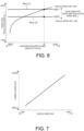
- FIG. 6 is a diagram showing map data of the target ENG revolution speed N ICE_ T according to the required discharge power.
- FIG. 6 shows the map data of the target ENG revolution speed N ICE_ T at the time of the retard discharge.
- the required discharge power is shown in absolute value.
- the map data at the time of the retard discharge is set based on a torque characteristic of the ENG torque TQ ICE that can be generated for each ENG revolution speed N ICE .
- the absolute value of the ENG torque TQ ICE tends to increase as the ENG revolution speed N ICE increases similarly to the general engine friction torque characteristic, and the power is proportional to the ENG revolution speed N ICE and the ENG torque TQ ICE .
- the map data at the time of the retard discharge has a characteristic that the target ENG revolution speed N ICE_ T becomes higher as the required discharge power is larger in absolute value.
- the map data is set under the condition that the absolute value of the ENG torque TQ ICE at the time of the retard discharge is the smallest.
- the map data at the time of the retard discharge has such characteristics as a result of reflecting a power consumption characteristic during the retard discharge, the map data at the time of the retard discharge and the map data at the time of the motoring are prepared separately. Therefore, in the ENG operation point calculation unit 36, the target ENG revolution speed N ICE_ T is calculated based on the power consumption characteristic during the retard discharge by referring to the map data shown in FIG. 6 .
- the map data of the target ENG revolution speed N ICE_ T is corrected according to the ENG oil temperature T OIL , and the friction of the engine 1 increases as the ENG oil temperature T OIL decreases. Therefore, the lower the ENG oil temperature T OIL , the lower the target ENG revolution speed N ICE_ T for the same required discharge power. For this reason, in the ENG operation point calculation unit 36, the lower the ENG oil temperature T OIL , the lower the target ENG revolution speed N ICE_ T for the same required discharge power is corrected.
- the map data at the time of the retard discharge may be further set according to a parameter representing a variation factor of the ENG torque TQ ICE such as the ENG oil temperature T OIL .
- a parameter representing a variation factor of the ENG torque TQ ICE such as the ENG oil temperature T OIL .
- the target ENG revolution speed N ICE_ T is further limited by a noise vibration upper limit revolution speed N ICE_ L from the viewpoint of noise vibration.
- the noise vibration upper limit revolution speed N ICE_ L is set in advance in accordance with the vehicle speed VSP, and increases as the vehicle speed VSP increases.
- the target ENG revolution speed N ICE_ T matches the noise vibration upper limit revolution speed N ICE_ L1 at the first vehicle speed VSP1.
- the target ENG revolution speed N ICE_ T does not exceed the noise vibration upper limit revolution speed N ICE_ L1, and thus is not limited to the noise vibration upper limit revolution speed N ICE_ L1.
- the target ENG revolution speed N ICE_ T exceeds the noise vibration upper limit revolution speed N ICE_ L2 at the second vehicle speed VSP2. For this reason, in this case, the target ENG revolution speed N ICE_ T is limited to the noise vibration upper limit revolution speed N ICE _L2.
- the target ENG revolution speed N ICE_ T to which the correction based on the ENG oil temperature T OIL and the limitation based on the noise vibration upper limit revolution speed N ICE_ L are applied is calculated as the final target ENG revolution speed N ICE_ T.
- the target ENG revolution speed N ICE_ T calculated by the ENG operation point calculation unit 36 is input to a generator controller 12.
- the generator controller 12 controls the generator 2 based on the input target ENG revolution speed N ICE_ T. Accordingly, the power consumption, that is, discharge is performed by motoring or retard discharge of the engine 1.
- the generator controller 12 constitutes the motor controller 10 together with a drive motor controller 11.
- the ENG operation mode determination unit 37 determines an operation mode of the engine 1 based on the input. When the target power EP ICE_ T is negative and the retard discharge flag is ON, the ENG operation mode determination unit 37 sets an ENG operation mode flag to the retard discharge. In addition, in the ENG operation mode determination unit 37, the ENG operation mode flag is set to the power generation operation when the target power EP ICE_ T is positive, and the ENG operation mode flag is set to the motoring when the target power EP ICE_ T is negative and the retard discharge flag is OFF.
- permitted output power POUT of the battery 6 is further input to the ENG operation mode determination unit 37.
- the permitted output power POUT is power that can be output from the battery 6, and the ENG operation mode flag is set to the retard discharge when the permitted output power POUT is larger than a predetermined value POUT1.
- the predetermined value POUT1 is a value for preventing an over-discharge state of the battery 6 due to a factor other than the SOC such as an environmental factor, and is set in advance. Even when the SOC is larger than the SOC at which the power generation request is made, for example, when the temperature of the battery 6 is extremely high or extremely low, the permitted output power POUT decreases.
- the case where the permitted output power POUT is equal to or less than the predetermined value POUT1 corresponds to the case where the battery 6 is in the over-discharge state. For this reason, in this case, the operation mode flag of the engine 1 can be set to the power generation operation.
- the ENG operation mode flag is input from the ENG operation mode determination unit 37 to the engine controller 20.
- the target ENG torque TQ ICE_ T calculated by the ENG operation point calculation unit 36 is also input to the engine controller 20.
- the engine controller 20 controls the engine 1 based on the input target ENG torque TQ ICE_ T and the input ENG operation mode flag. Accordingly, when power is generated, the generator 2 is driven by the engine 1. When the retard discharge is performed, combustion in which the ignition timing is retarded is performed in the engine 1.
- the ENG operation mode flag is set to the retard discharge when the permitted output power POUT is larger than the predetermined value POUT1. For this reason, in a case where the permitted output power POUT is larger than the predetermined value POUT1, even when a request for idol speed cotrol (ISC) of the engine 1 is made, the retard discharge is performed in preference to the ISC request.
- ISC idol speed cotrol
- the ENG operation mode flag set by the ENG operation mode determination unit 37, the ENG revolution speed N ICE , the ENG oil temperature T OIL , and the vehicle speed VSP are input to the ENG power consumption calculation unit 38.
- the ENG power consumption calculation unit 38 calculates ENG power consumption that is power consumption obtained by the motoring or the retard discharge.
- the ENG power consumption is power consumption of a power generation unit including the engine 1 and the generator 2.
- the retard discharge flag When the retard discharge flag is ON, the power consumption obtained by the retard discharge is calculated as the ENG power consumption. When the retard discharge flag is OFF, the power consumption obtained by the motoring is calculated as the ENG power consumption.
- the calculated ENG power consumption is a calculated value of power consumption obtained by the retard discharge or the motoring, and corresponds to an estimated power consumption value.
- the ENG power consumption is calculated based on the ENG revolution speed N ICE .
- the ENG power consumption is negative, and the higher the ENG revolution speed N ICE is, the larger the ENG power consumption is calculated in absolute value.
- the ENG power consumption is set in advance by map data according to the ENG revolution speed N ICE .
- map data map data referred to at the time of motoring and map data referred to at the time of retard discharge are separately prepared.
- the target ENG revolution speed N ICE_ T is replaced with the ENG revolution speed N ICE in the map data shown in FIG. 6 , and the required discharge power is replaced with the ENG power consumption. Therefore, the ENG power consumption calculation unit 38 calculates the ENG power consumption based on the power consumption characteristic during the retard discharge according to the ENG revolution speed N ICE by referring to the map data of the ENG power consumption at the time of the retard discharge.
- the ENG power consumption is corrected based on the ENG oil temperature T OIL , and the corrected ENG power consumption is calculated as the final ENG power consumption. For the same ENG revolution speed N ICE , the lower the ENG oil temperature T OIL , the larger the ENG power consumption is corrected in absolute value.
- the ENG power consumption calculation unit 38 gradually changes the ENG power consumption from the ENG power consumption obtained by the retard discharge to the ENG power consumption obtained by the motoring.
- the ENG power consumption constantly obtained by the motoring is larger in absolute value than the ENG power consumption constantly obtained by the retard discharge. For this reason, the ENG power consumption calculation unit 38 gradually increases the ENG power consumption in absolute value during the transition.
- the ENG power consumption calculation unit 38 further changes a power change rate according to the vehicle speed VSP during the transition as described below.
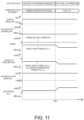
- FIG. 7 is a diagram showing the power change rate according to the vehicle speed VSP.
- the power change rate is a change rate of the ENG power consumption at the time of transition from the retard discharge to the motoring, and the power change rate increases as the vehicle speed VSP increases. Accordingly, the higher the vehicle speed VSP, the faster the transition from the retard discharge to the motoring is performed.
- the auxiliary machine power consumption and the permitted input power PIN are input to the regenerative torque limit calculation unit 39.
- the permitted input power PIN is power that can be input to the battery 6, and is zero or a negative value.
- the regenerative torque limit calculation unit 39 calculates an allowable regenerative torque TQ MOT_ L of the drive motor 3 based on a sum of the ENG power consumption, the auxiliary machine power consumption, and the permitted input power PIN.
- the sum of the ENG power consumption, the auxiliary machine power consumption, and the permitted input power PIN constitutes system regenerative maximum power PMAX.
- the system regenerative maximum power PMAX is the maximum power in absolute value that can be regenerated in the vehicle 100, and indicates the maximum power that can be accepted by the vehicle 100.
- a regenerative torque corresponding to the system regenerative maximum power PMAX is calculated as an allowable regenerative torque TQ MOT _L. Regeneration cannot be performed with a drive torque Q MOT that is larger in absolute value than the allowable regenerative torque TQ MOT _L. Therefore, the allowable regenerative torque can be said to be a regenerative limit torque.
- the calculated allowable regenerative torque TQ MOT_ L is input to the regenerative torque limiting unit 40.
- the regenerative torque limiting unit 40 limits the target drive torque TQ MOT_ T of the drive motor 3 based on the input allowable regenerative torque TQ MOT _L.
- the target drive torque TQ MOT_ T represents a target regenerative torque in the case of negative.
- the target drive torque TQ MOT_ T is limited to the allowable regenerative torque TQ MOT _L.
- the target drive torque TQ MOT_ T is limited by an allowable regenerative torque TQ MOT_ Lr at the time of the retard discharge, so that the regenerative torque is limited according to the ENG power consumption due to the retard discharge.
- the target drive torque TQ MOT_ T after the limitation is applied is input to the drive motor controller 11 as the final target drive torque TQ MOT_ T, and the drive motor controller 11 drives the drive motor 3 based on the input target drive torque TQ MOT_ T.
- the target drive torque TQ MOT_ T is negative, regeneration is performed.
- the target drive torque TQ MOT_ T after the limitation is applied is also input to the target drive power calculation unit 32.
- FIG. 8 is a flowchart showing an example of discharge control performed by the controller 50.
- FIG. 8 shows a case where the drive mode is the S mode.
- the controller 50 performs the processing of the flowchart shown in FIG. 8 , and thus a control unit is functionally implemented.
- the processing of the flowchart shown in FIG. 8 can be repeatedly executed.
- step S1 the controller 50 determines whether the target power EP ICE_ T is less than zero. If an affirmative determination is made in step S1, it is determined that the target power EP ICE_ T is the target discharge power and there is a discharge request.
- the discharge request is a discharge request for causing the generator 2 to perform discharge, and the generator 2 performs discharge by driving the engine 1 based on such a discharge request.
- the target power EP ICE_ T becomes negative, for example, when the target drive power EP MOT_ T becomes negative and there is no power generation request or discharge prohibition request having a higher priority than the target drive power EP MOT_ T. Therefore, when there is a discharge request, for example, the discharge is performed at the time of regeneration including the start of regeneration.
- the case where the target power EP ICE_ T is less than zero includes a case where the battery 6 is fully charged. In the case where the battery 6 is fully charged, negative power corresponding to the SOC control power request is added to the negative target drive power EP MOT_ T, and as a result, the target power EP ICE_ T becomes less than zero. If an affirmative determination is made in step S1, the processing proceeds to step S2.
- step S2 the controller 50 determines whether the GPF temperature T is higher than the threshold value Tref. That is, it is determined whether the fuel cut prohibition condition is satisfied. If an affirmative determination is made in step S2, the GPF state flag is set to ON, and the controller 50 prohibits the fuel cut in step S3.
- step S4 the controller 50 determines whether the permitted output power POUT of the battery 6 is larger than the predetermined value POUT1. If a negative determination is made in step S4, the processing is temporarily ended. In this case, the battery 6 is determined to be in an over-discharge state, and thus the power generation operation of the engine 1 can be performed. If an affirmative determination is made in step S4, the battery 6 is determined not to be in an over-discharge state, and the processing proceeds to step S5.
- step S5 the controller 50 executes the retard discharge. Accordingly, it is possible to discharge the battery 6 while suppressing overheating of the GPF, thereby increasing the room for regeneration. Therefore, even when the fuel cut is prohibited and the battery 6 is fully charged, it is possible to obtain the deceleration by the regeneration.
- step S2 If a negative determination is made in step S2, the GPF state flag is OFF, and the controller 50 executes the fuel cut of the engine 1 in step S6 and executes the motoring in step S7. That is, in this case, the GPF does not overheat even when the motoring is performed, and thus the battery 6 is discharged by the motoring. In this case, regeneration corresponding to a discharge amount can be performed by the motoring, and thus the deceleration larger in absolute value than that in the case of performing the retard discharge is secured.
- step S7 When the retard discharge was performed in the previous routine, the transition from the retard discharge to the motoring is started in step S7. At this time, the controller 50 gradually changes the ENG power consumption. The controller 50 gradually changes the ENG power consumption from the ENG power consumption obtained by the retard discharge to the ENG power consumption obtained by the motoring. The gradual change of the ENG power consumption is continuously performed until the ENG power consumption reaches the ENG power consumption obtained by the motoring. After step S7, the processing temporarily ends.
- step S1 If a negative determination is made in step S1, the discharge request is eliminated. For this reason, the retard discharge and the motoring are stopped. If a negative determination is made in step S1, it is determined in step S8 whether the GPF temperature T is higher than the threshold value Tref. If an affirmative determination is made in step S8, the fuel cut is prohibited in step S9. In this case, the power generation operation of the engine 1 can be performed. If a negative determination is made in step S8, the processing is temporarily ended. In this case, since the GPF state flag is OFF and the fuel cut is permitted, the power generation operation and the operation stop of the engine 1 can be performed.
- step S1 to step S4, step S8, and step S9 can be performed by the vehicle controller 30.
- the processing of step S5 can be performed by the motor controller 10 and the engine controller 20.
- the processing of step S6 can be performed by the engine controller 20, and the processing of step S7 can be performed by the motor controller 10.
- FIG. 9 is a diagram showing a first example of a timing chart corresponding to FIG. 8 .
- FIG. 9 shows a case where the retard discharge is performed.
- the vehicle 100 travels on an upslope at a constant vehicle speed VSP.
- the accelerator opening APO is larger than zero, and the target drive torque TQ MOT_ T of the drive motor 3 and the target drive power EP MOT_ T corresponding to the target drive torque TQ MOT_ T are positive.
- the GPF state flag is ON, and an operating state of the engine 1 is a positive torque operation in which a positive torque is generated by combustion. For this reason, an actual ENG torque TQ ICE_ A of the engine 1 is positive, and an actual GEN torque TQ GEN_ A of the generator 2 is negative.
- a GEN revolution speed N GEN of the generator 2 is greater than zero.
- the vehicle 100 Before the timing T1, the vehicle 100 approaches a downhill. For this reason, the constant accelerator opening APO starts to decrease, and accordingly, the target drive torque TQ MOT_ T and the target drive power EP MOT_ T also start to decrease.
- the accelerator opening APO becomes zero before the timing T1, and the target drive torque TQ MOT_ T becomes negative accordingly, so that the target drive power EP MOT_ T becomes negative at the timing T1.
- the regeneration is started, and the discharge request is made in a fuel cut prohibition state. For this reason, the retard discharge is also started, and the operating state of the engine 1 becomes a negative torque operation in which a negative torque is generated in a combustion state. Since the regeneration is started, the permitted input power PIN of the battery 6 starts to gradually decrease in absolute value.
- the allowable regenerative torque TQ MOT_ L and the system regenerative maximum power PMAX decrease (increase in absolute value) by the amount of discharge due to the retard discharge.
- the target drive torque TQ MOT_ T is further limited by the allowable regenerative torque TQ MOT_ L, and decreases to the allowable regenerative torque TQ MOT _L.
- the target drive power EP MOT_ T decreases to the system regenerative maximum power PMAX. As a result, a regeneration amount increases by the amount of discharge due to the retard discharge.
- the deceleration larger in absolute value than that in the case of not performing the retard discharge is secured.
- the allowable regenerative torque TQ MOT_ L and the target drive power EP MOT_ T do not become zero, and the deceleration is ensured.
- FIG. 10 is a diagram showing a second example of the timing chart corresponding to FIG. 8 .
- FIG. 10 shows a case where the motoring is performed.
- a state before a timing T11 is the same as that in FIG. 9 except that the GPF state flag is OFF.
- the discharge request is made in a state in which the fuel cut is not prohibited.
- the motoring is started, and the operating state of the engine 1 becomes a fuel cut state, that is, an operation stop state.
- the engine 1 in an operation stop state is driven by the generator 2, and power is consumed more than in the retard discharge.
- the discharge power of the generator 2 indicated by hatching becomes larger than that in the case of FIG. 9
- the allowable regenerative torque TQ MOT_ L and the system regenerative maximum power PMAX also become larger in absolute value than those in the case of FIG. 9 .
- the target drive torque TQ MOT_ T and the target drive power EP MOT_ T are also larger in absolute value than those in FIG. 9 , including the case where the permitted input power PIN becomes zero at a timing T13. Therefore, the deceleration larger in absolute value than that in the case of the retard discharge is secured.
- FIG. 11 is a diagram showing a third example of the timing chart corresponding to FIG. 8 .
- FIG. 11 shows a transition from the retard discharge to the motoring.
- the fuel cut of the engine 1 is prohibited, and the retard discharge is performed as the negative torque operation.
- the engine 1, which is undergoing combustion is driven by the generator 2.
- the GEN torque TQ GEN of the generator 2 is larger than zero.
- the vehicle 100 travels on a downhill at a constant vehicle speed VSP and performs regeneration.
- the accelerator opening APO is zero, and the target drive torque TQ MOT_ T and the target drive power EP MOT_ T are negative.
- the target drive torque TQ MOT_ T is limited to the allowable regenerative torque TQ MOT _L.
- the GPF state flag changes from ON to OFF. For this reason, the fuel cut of the engine 1 is performed and the motoring is started. As a result, the transition from the retard discharge to the motoring is performed. Accordingly, the target drive torque TQ MOT_ T and the target drive power EP MOT_ T decrease and the absolute values thereof increase, and thus the GEN torque TQ GEN also increases.
- the ENG power consumption is gradually changed from the ENG power consumption obtained by the retard discharge to the ENG power consumption obtained by the motoring. Accordingly, the allowable regenerative torque TQ MOT_ L gradually decreases, and as a result, the target drive torque TQ MOT_ T gradually decreases while being limited to the allowable regenerative torque TQ MOT _L. As a result, deceleration having a maximum potential that can be achieved by the motoring can be obtained while suppressing the driver from feeling uncomfortable.
- the discharge can be performed even during the fuel cut prohibition in which the GPF may overheat due to oxygen supply. For this reason, the discharge can be performed while protecting the GPF. As a result, it is possible to increase the room for regeneration at the time of regeneration even when the fuel cut is prohibited, and it is possible to ensure deceleration.
- the retard discharge is preferentially performed. According to such a method, it is possible to perform retard combustion while preventing the battery 6 from entering an over-discharge state due to a factor other than the SOC. For this reason, even when the battery 6 may be in an over-discharge state due to a factor other than the SOC, it is possible to secure power for starting the engine 1 next time, and it is possible to prevent drive assist power supplied from the battery 6 from decreasing.
- the ENG power consumption is gradually changed from the ENG power consumption obtained by the retard discharge to the ENG power consumption obtained by the motoring. According to such a method, it is possible to obtain deceleration having a maximum potential that can be achieved by the motoring while suppressing the driver from feeling uncomfortable at the time of transition from the retard discharge to the motoring of the engine 1.
- the target ENG revolution speed N ICE_ T is calculated based on the power consumption characteristic during the retard discharge by referring to the map data of the target ENG revolution speed N ICE_ T at the time of the retard discharge shown in FIG. 6 .
- the target ENG revolution speed N ICE_ T is corrected according to the ENG oil temperature T OIL . According to such a method, the deceleration can be ensured while satisfying the discharge power required during the retard discharge.
- the negative target drive torque TQ MOT_ T is limited by the allowable regenerative torque TQ MOT_ L, and as a result, the regenerative torque of the drive motor 3 is limited according to the ENG power consumption due to the retard discharge.
- the regenerative power can be limited in accordance with the ENG power consumption due to the retard discharge, and thus it is possible to continuously generate the deceleration while preventing the battery 6 from being fully charged.
- the power consumption operation may be a negative torque operation in which the engine 1 is driven by the generator 2 during idling operation to generate a negative torque in the engine 1.
Landscapes
- Engineering & Computer Science (AREA)
- Chemical & Material Sciences (AREA)
- Combustion & Propulsion (AREA)
- Mechanical Engineering (AREA)
- Transportation (AREA)
- Automation & Control Theory (AREA)
- General Engineering & Computer Science (AREA)
- Physics & Mathematics (AREA)
- Mathematical Physics (AREA)
- Electric Propulsion And Braking For Vehicles (AREA)
- Hybrid Electric Vehicles (AREA)
- Control Of Vehicle Engines Or Engines For Specific Uses (AREA)
- Processes For Solid Components From Exhaust (AREA)
Applications Claiming Priority (1)
| Application Number | Priority Date | Filing Date | Title |
|---|---|---|---|
| PCT/JP2021/032915 WO2023037420A1 (ja) | 2021-09-07 | 2021-09-07 | 車両の制御方法及び車両 |
Publications (3)
| Publication Number | Publication Date |
|---|---|
| EP4400376A1 EP4400376A1 (en) | 2024-07-17 |
| EP4400376A4 EP4400376A4 (en) | 2024-11-20 |
| EP4400376B1 true EP4400376B1 (en) | 2025-05-14 |
Family
ID=85507307
Family Applications (1)
| Application Number | Title | Priority Date | Filing Date |
|---|---|---|---|
| EP21956717.9A Active EP4400376B1 (en) | 2021-09-07 | 2021-09-07 | Method for controlling vehicle, and vehicle |
Country Status (6)
| Country | Link |
|---|---|
| US (1) | US12434686B2 (https=) |
| EP (1) | EP4400376B1 (https=) |
| JP (1) | JP7568123B2 (https=) |
| CN (1) | CN117897318A (https=) |
| MX (1) | MX2024002813A (https=) |
| WO (1) | WO2023037420A1 (https=) |
Families Citing this family (2)
| Publication number | Priority date | Publication date | Assignee | Title |
|---|---|---|---|---|
| JP7726136B2 (ja) * | 2022-06-29 | 2025-08-20 | トヨタ自動車株式会社 | ハイブリッド車両の制御装置 |
| KR20240011928A (ko) * | 2022-07-19 | 2024-01-29 | 현대자동차주식회사 | 하이브리드 자동차 및 그를 위한 크립 토크 제어 방법 |
Family Cites Families (15)
| Publication number | Priority date | Publication date | Assignee | Title |
|---|---|---|---|---|
| JP2004225564A (ja) | 2003-01-20 | 2004-08-12 | Hitachi Unisia Automotive Ltd | ハイブリッド車両の制御装置 |
| JP2006009674A (ja) * | 2004-06-25 | 2006-01-12 | Denso Corp | 内燃機関の制御装置 |
| EP2411646B1 (en) * | 2009-03-24 | 2020-07-08 | Volvo Lastvagnar AB | Method for controlling an exhaust gas temperature |
| US8657721B2 (en) * | 2011-03-15 | 2014-02-25 | GM Global Technology Operations LLC | Driveline stiffness relaxation systems and methods for DFCO operation |
| US10059338B2 (en) * | 2015-12-03 | 2018-08-28 | Ford Global Technologies, Llc | Method and system for regenerating a gasoline particulate filter |
| JP6673139B2 (ja) | 2016-10-19 | 2020-03-25 | トヨタ自動車株式会社 | ハイブリッド自動車 |
| JP6468298B2 (ja) * | 2017-01-30 | 2019-02-13 | トヨタ自動車株式会社 | ハイブリッド自動車 |
| WO2019116582A1 (ja) * | 2017-12-15 | 2019-06-20 | 日産自動車株式会社 | ハイブリッド車両の制御方法及び制御装置 |
| JP2020075528A (ja) * | 2018-11-05 | 2020-05-21 | トヨタ自動車株式会社 | ハイブリッド自動車 |
| CN112888609B (zh) * | 2018-11-08 | 2024-05-10 | 日产自动车株式会社 | 混合动力车辆的控制方法以及混合动力车辆的控制装置 |
| JP7155938B2 (ja) * | 2018-11-22 | 2022-10-19 | トヨタ自動車株式会社 | ハイブリッド自動車 |
| JP2020104668A (ja) * | 2018-12-27 | 2020-07-09 | トヨタ自動車株式会社 | 車両の制御装置 |
| JP2020112082A (ja) * | 2019-01-11 | 2020-07-27 | トヨタ自動車株式会社 | エンジン装置 |
| JP2020111164A (ja) * | 2019-01-11 | 2020-07-27 | トヨタ自動車株式会社 | ハイブリッド自動車 |
| JP2021054331A (ja) * | 2019-09-30 | 2021-04-08 | ダイハツ工業株式会社 | 電動車両用制御装置 |
-
2021
- 2021-09-07 JP JP2023546603A patent/JP7568123B2/ja active Active
- 2021-09-07 CN CN202180102062.1A patent/CN117897318A/zh active Pending
- 2021-09-07 US US18/689,330 patent/US12434686B2/en active Active
- 2021-09-07 MX MX2024002813A patent/MX2024002813A/es unknown
- 2021-09-07 WO PCT/JP2021/032915 patent/WO2023037420A1/ja not_active Ceased
- 2021-09-07 EP EP21956717.9A patent/EP4400376B1/en active Active
Also Published As
| Publication number | Publication date |
|---|---|
| US20240326777A1 (en) | 2024-10-03 |
| EP4400376A4 (en) | 2024-11-20 |
| CN117897318A (zh) | 2024-04-16 |
| US12434686B2 (en) | 2025-10-07 |
| JPWO2023037420A1 (https=) | 2023-03-16 |
| MX2024002813A (es) | 2024-03-19 |
| EP4400376A1 (en) | 2024-07-17 |
| JP7568123B2 (ja) | 2024-10-16 |
| WO2023037420A1 (ja) | 2023-03-16 |
Similar Documents
| Publication | Publication Date | Title |
|---|---|---|
| EP3725615B1 (en) | Method and device for controlling hybrid vehicle | |
| US7967091B2 (en) | Hybrid electric vehicle powertrain with engine start and transmission shift arbitration | |
| JP6927328B2 (ja) | ハイブリッド車両の制御方法、及び、制御装置 | |
| US9376970B2 (en) | Vehicle control device | |
| JP2011239605A (ja) | 車両の制御装置 | |
| EP4400376B1 (en) | Method for controlling vehicle, and vehicle | |
| EP4400375B1 (en) | Method for controlling vehicle and vehicle | |
| EP4400377B1 (en) | Method for controlling vehicle and vehicle | |
| JP5741068B2 (ja) | 電動車両 | |
| JP2004270512A (ja) | ハイブリッド車両の制御装置 | |
| US12280766B1 (en) | Control method for vehicle and vehicle | |
| JP2004034844A (ja) | 車両のトルク制御装置及びトルク制御方法 | |
| JP2004211575A (ja) | 車輌の制御装置 | |
| US12077148B2 (en) | Control method for hybrid vehicle and control device for hybrid vehicle | |
| JP7521678B2 (ja) | シリーズハイブリッド車両の制御方法及びシリーズハイブリッド車両の制御装置 | |
| JP7757912B2 (ja) | 制御装置 | |
| JP7771901B2 (ja) | 制御装置 | |
| CN119773719A (zh) | 混合动力电动车辆的控制装置 | |
| JP2023017421A (ja) | 車両の充電システム | |
| JP2007202264A (ja) | 車両およびその制御方法 | |
| JP2004150291A (ja) | ハイブリッド車両の制御装置 |
Legal Events
| Date | Code | Title | Description |
|---|---|---|---|
| STAA | Information on the status of an ep patent application or granted ep patent |
Free format text: STATUS: THE INTERNATIONAL PUBLICATION HAS BEEN MADE |
|
| PUAI | Public reference made under article 153(3) epc to a published international application that has entered the european phase |
Free format text: ORIGINAL CODE: 0009012 |
|
| STAA | Information on the status of an ep patent application or granted ep patent |
Free format text: STATUS: REQUEST FOR EXAMINATION WAS MADE |
|
| 17P | Request for examination filed |
Effective date: 20240329 |
|
| AK | Designated contracting states |
Kind code of ref document: A1 Designated state(s): AL AT BE BG CH CY CZ DE DK EE ES FI FR GB GR HR HU IE IS IT LI LT LU LV MC MK MT NL NO PL PT RO RS SE SI SK SM TR |
|
| A4 | Supplementary search report drawn up and despatched |
Effective date: 20241023 |
|
| RIC1 | Information provided on ipc code assigned before grant |
Ipc: B60W 30/18 20120101ALI20241017BHEP Ipc: B60W 10/08 20060101ALI20241017BHEP Ipc: B60K 6/46 20071001ALI20241017BHEP Ipc: B60W 10/06 20060101ALI20241017BHEP Ipc: B60W 20/16 20160101AFI20241017BHEP |
|
| DAV | Request for validation of the european patent (deleted) | ||
| DAX | Request for extension of the european patent (deleted) | ||
| GRAP | Despatch of communication of intention to grant a patent |
Free format text: ORIGINAL CODE: EPIDOSNIGR1 |
|
| STAA | Information on the status of an ep patent application or granted ep patent |
Free format text: STATUS: GRANT OF PATENT IS INTENDED |
|
| RIC1 | Information provided on ipc code assigned before grant |
Ipc: B60W 30/18 20120101ALI20250129BHEP Ipc: B60W 10/08 20060101ALI20250129BHEP Ipc: B60K 6/46 20071001ALI20250129BHEP Ipc: B60W 10/06 20060101ALI20250129BHEP Ipc: B60W 20/16 20160101AFI20250129BHEP |
|
| GRAJ | Information related to disapproval of communication of intention to grant by the applicant or resumption of examination proceedings by the epo deleted |
Free format text: ORIGINAL CODE: EPIDOSDIGR1 |
|
| INTG | Intention to grant announced |
Effective date: 20250217 |
|
| STAA | Information on the status of an ep patent application or granted ep patent |
Free format text: STATUS: REQUEST FOR EXAMINATION WAS MADE |
|
| GRAP | Despatch of communication of intention to grant a patent |
Free format text: ORIGINAL CODE: EPIDOSNIGR1 |
|
| STAA | Information on the status of an ep patent application or granted ep patent |
Free format text: STATUS: GRANT OF PATENT IS INTENDED |
|
| GRAS | Grant fee paid |
Free format text: ORIGINAL CODE: EPIDOSNIGR3 |
|
| GRAA | (expected) grant |
Free format text: ORIGINAL CODE: 0009210 |
|
| STAA | Information on the status of an ep patent application or granted ep patent |
Free format text: STATUS: THE PATENT HAS BEEN GRANTED |
|
| INTC | Intention to grant announced (deleted) | ||
| INTG | Intention to grant announced |
Effective date: 20250404 |
|
| AK | Designated contracting states |
Kind code of ref document: B1 Designated state(s): AL AT BE BG CH CY CZ DE DK EE ES FI FR GB GR HR HU IE IS IT LI LT LU LV MC MK MT NL NO PL PT RO RS SE SI SK SM TR |
|
| REG | Reference to a national code |
Ref country code: GB Ref legal event code: FG4D |
|
| REG | Reference to a national code |
Ref country code: CH Ref legal event code: EP |
|
| REG | Reference to a national code |
Ref country code: DE Ref legal event code: R096 Ref document number: 602021030974 Country of ref document: DE |
|
| REG | Reference to a national code |
Ref country code: IE Ref legal event code: FG4D |
|
| PGFP | Annual fee paid to national office [announced via postgrant information from national office to epo] |
Ref country code: FR Payment date: 20250617 Year of fee payment: 5 |
|
| REG | Reference to a national code |
Ref country code: NL Ref legal event code: MP Effective date: 20250514 |
|
| PG25 | Lapsed in a contracting state [announced via postgrant information from national office to epo] |
Ref country code: ES Free format text: LAPSE BECAUSE OF FAILURE TO SUBMIT A TRANSLATION OF THE DESCRIPTION OR TO PAY THE FEE WITHIN THE PRESCRIBED TIME-LIMIT Effective date: 20250514 Ref country code: PT Free format text: LAPSE BECAUSE OF FAILURE TO SUBMIT A TRANSLATION OF THE DESCRIPTION OR TO PAY THE FEE WITHIN THE PRESCRIBED TIME-LIMIT Effective date: 20250915 Ref country code: FI Free format text: LAPSE BECAUSE OF FAILURE TO SUBMIT A TRANSLATION OF THE DESCRIPTION OR TO PAY THE FEE WITHIN THE PRESCRIBED TIME-LIMIT Effective date: 20250514 |
|
| PGFP | Annual fee paid to national office [announced via postgrant information from national office to epo] |
Ref country code: DE Payment date: 20250716 Year of fee payment: 5 |
|
| REG | Reference to a national code |
Ref country code: LT Ref legal event code: MG9D |
|
| PG25 | Lapsed in a contracting state [announced via postgrant information from national office to epo] |
Ref country code: NO Free format text: LAPSE BECAUSE OF FAILURE TO SUBMIT A TRANSLATION OF THE DESCRIPTION OR TO PAY THE FEE WITHIN THE PRESCRIBED TIME-LIMIT Effective date: 20250814 Ref country code: GR Free format text: LAPSE BECAUSE OF FAILURE TO SUBMIT A TRANSLATION OF THE DESCRIPTION OR TO PAY THE FEE WITHIN THE PRESCRIBED TIME-LIMIT Effective date: 20250815 |
|
| PG25 | Lapsed in a contracting state [announced via postgrant information from national office to epo] |
Ref country code: NL Free format text: LAPSE BECAUSE OF FAILURE TO SUBMIT A TRANSLATION OF THE DESCRIPTION OR TO PAY THE FEE WITHIN THE PRESCRIBED TIME-LIMIT Effective date: 20250514 Ref country code: PL Free format text: LAPSE BECAUSE OF FAILURE TO SUBMIT A TRANSLATION OF THE DESCRIPTION OR TO PAY THE FEE WITHIN THE PRESCRIBED TIME-LIMIT Effective date: 20250514 |
|
| REG | Reference to a national code |
Ref country code: AT Ref legal event code: MK05 Ref document number: 1794556 Country of ref document: AT Kind code of ref document: T Effective date: 20250514 |
|
| PG25 | Lapsed in a contracting state [announced via postgrant information from national office to epo] |
Ref country code: BG Free format text: LAPSE BECAUSE OF FAILURE TO SUBMIT A TRANSLATION OF THE DESCRIPTION OR TO PAY THE FEE WITHIN THE PRESCRIBED TIME-LIMIT Effective date: 20250514 |
|
| PGFP | Annual fee paid to national office [announced via postgrant information from national office to epo] |
Ref country code: GB Payment date: 20250717 Year of fee payment: 5 |
|
| PG25 | Lapsed in a contracting state [announced via postgrant information from national office to epo] |
Ref country code: HR Free format text: LAPSE BECAUSE OF FAILURE TO SUBMIT A TRANSLATION OF THE DESCRIPTION OR TO PAY THE FEE WITHIN THE PRESCRIBED TIME-LIMIT Effective date: 20250514 |
|
| PG25 | Lapsed in a contracting state [announced via postgrant information from national office to epo] |
Ref country code: AT Free format text: LAPSE BECAUSE OF FAILURE TO SUBMIT A TRANSLATION OF THE DESCRIPTION OR TO PAY THE FEE WITHIN THE PRESCRIBED TIME-LIMIT Effective date: 20250514 |
|
| PG25 | Lapsed in a contracting state [announced via postgrant information from national office to epo] |
Ref country code: RS Free format text: LAPSE BECAUSE OF FAILURE TO SUBMIT A TRANSLATION OF THE DESCRIPTION OR TO PAY THE FEE WITHIN THE PRESCRIBED TIME-LIMIT Effective date: 20250814 |
|
| PG25 | Lapsed in a contracting state [announced via postgrant information from national office to epo] |
Ref country code: IS Free format text: LAPSE BECAUSE OF FAILURE TO SUBMIT A TRANSLATION OF THE DESCRIPTION OR TO PAY THE FEE WITHIN THE PRESCRIBED TIME-LIMIT Effective date: 20250914 |
|
| PG25 | Lapsed in a contracting state [announced via postgrant information from national office to epo] |
Ref country code: LV Free format text: LAPSE BECAUSE OF FAILURE TO SUBMIT A TRANSLATION OF THE DESCRIPTION OR TO PAY THE FEE WITHIN THE PRESCRIBED TIME-LIMIT Effective date: 20250514 |
|
| PG25 | Lapsed in a contracting state [announced via postgrant information from national office to epo] |
Ref country code: DK Free format text: LAPSE BECAUSE OF FAILURE TO SUBMIT A TRANSLATION OF THE DESCRIPTION OR TO PAY THE FEE WITHIN THE PRESCRIBED TIME-LIMIT Effective date: 20250514 Ref country code: SM Free format text: LAPSE BECAUSE OF FAILURE TO SUBMIT A TRANSLATION OF THE DESCRIPTION OR TO PAY THE FEE WITHIN THE PRESCRIBED TIME-LIMIT Effective date: 20250514 |
|
| PG25 | Lapsed in a contracting state [announced via postgrant information from national office to epo] |
Ref country code: CZ Free format text: LAPSE BECAUSE OF FAILURE TO SUBMIT A TRANSLATION OF THE DESCRIPTION OR TO PAY THE FEE WITHIN THE PRESCRIBED TIME-LIMIT Effective date: 20250514 |
|
| PG25 | Lapsed in a contracting state [announced via postgrant information from national office to epo] |
Ref country code: EE Free format text: LAPSE BECAUSE OF FAILURE TO SUBMIT A TRANSLATION OF THE DESCRIPTION OR TO PAY THE FEE WITHIN THE PRESCRIBED TIME-LIMIT Effective date: 20250514 |
|
| PG25 | Lapsed in a contracting state [announced via postgrant information from national office to epo] |
Ref country code: SK Free format text: LAPSE BECAUSE OF FAILURE TO SUBMIT A TRANSLATION OF THE DESCRIPTION OR TO PAY THE FEE WITHIN THE PRESCRIBED TIME-LIMIT Effective date: 20250514 |
|
| PG25 | Lapsed in a contracting state [announced via postgrant information from national office to epo] |
Ref country code: IT Free format text: LAPSE BECAUSE OF FAILURE TO SUBMIT A TRANSLATION OF THE DESCRIPTION OR TO PAY THE FEE WITHIN THE PRESCRIBED TIME-LIMIT Effective date: 20250514 |
|
| REG | Reference to a national code |
Ref country code: DE Ref legal event code: R097 Ref document number: 602021030974 Country of ref document: DE |
|
| PG25 | Lapsed in a contracting state [announced via postgrant information from national office to epo] |
Ref country code: RO Free format text: LAPSE BECAUSE OF FAILURE TO SUBMIT A TRANSLATION OF THE DESCRIPTION OR TO PAY THE FEE WITHIN THE PRESCRIBED TIME-LIMIT Effective date: 20250514 |
|
| PLBE | No opposition filed within time limit |
Free format text: ORIGINAL CODE: 0009261 |
|
| STAA | Information on the status of an ep patent application or granted ep patent |
Free format text: STATUS: NO OPPOSITION FILED WITHIN TIME LIMIT |
|
| REG | Reference to a national code |
Ref country code: CH Ref legal event code: L10 Free format text: ST27 STATUS EVENT CODE: U-0-0-L10-L00 (AS PROVIDED BY THE NATIONAL OFFICE) Effective date: 20260325 |
|
| 26N | No opposition filed |
Effective date: 20260217 |