EP4400264A1 - Elektrohandwerkzeug - Google Patents
Elektrohandwerkzeug Download PDFInfo
- Publication number
- EP4400264A1 EP4400264A1 EP23151247.6A EP23151247A EP4400264A1 EP 4400264 A1 EP4400264 A1 EP 4400264A1 EP 23151247 A EP23151247 A EP 23151247A EP 4400264 A1 EP4400264 A1 EP 4400264A1
- Authority
- EP
- European Patent Office
- Prior art keywords
- electric hand
- hand tool
- sealing
- device part
- intake
- Prior art date
- Legal status (The legal status is an assumption and is not a legal conclusion. Google has not performed a legal analysis and makes no representation as to the accuracy of the status listed.)
- Withdrawn
Links
Images



Classifications
-
- B—PERFORMING OPERATIONS; TRANSPORTING
- B25—HAND TOOLS; PORTABLE POWER-DRIVEN TOOLS; MANIPULATORS
- B25D—PERCUSSIVE TOOLS
- B25D17/00—Details of, or accessories for, portable power-driven percussive tools
- B25D17/04—Handles; Handle mountings
- B25D17/043—Handles resiliently mounted relative to the hammer housing
-
- B—PERFORMING OPERATIONS; TRANSPORTING
- B25—HAND TOOLS; PORTABLE POWER-DRIVEN TOOLS; MANIPULATORS
- B25F—COMBINATION OR MULTI-PURPOSE TOOLS NOT OTHERWISE PROVIDED FOR; DETAILS OR COMPONENTS OF PORTABLE POWER-DRIVEN TOOLS NOT PARTICULARLY RELATED TO THE OPERATIONS PERFORMED AND NOT OTHERWISE PROVIDED FOR
- B25F5/00—Details or components of portable power-driven tools not particularly related to the operations performed and not otherwise provided for
- B25F5/006—Vibration damping means
-
- B—PERFORMING OPERATIONS; TRANSPORTING
- B25—HAND TOOLS; PORTABLE POWER-DRIVEN TOOLS; MANIPULATORS
- B25F—COMBINATION OR MULTI-PURPOSE TOOLS NOT OTHERWISE PROVIDED FOR; DETAILS OR COMPONENTS OF PORTABLE POWER-DRIVEN TOOLS NOT PARTICULARLY RELATED TO THE OPERATIONS PERFORMED AND NOT OTHERWISE PROVIDED FOR
- B25F5/00—Details or components of portable power-driven tools not particularly related to the operations performed and not otherwise provided for
- B25F5/008—Cooling means
-
- F—MECHANICAL ENGINEERING; LIGHTING; HEATING; WEAPONS; BLASTING
- F16—ENGINEERING ELEMENTS AND UNITS; GENERAL MEASURES FOR PRODUCING AND MAINTAINING EFFECTIVE FUNCTIONING OF MACHINES OR INSTALLATIONS; THERMAL INSULATION IN GENERAL
- F16J—PISTONS; CYLINDERS; SEALINGS
- F16J15/00—Sealings
- F16J15/02—Sealings between relatively-stationary surfaces
- F16J15/021—Sealings between relatively-stationary surfaces with elastic packing
- F16J15/022—Sealings between relatively-stationary surfaces with elastic packing characterised by structure or material
- F16J15/024—Sealings between relatively-stationary surfaces with elastic packing characterised by structure or material the packing being locally weakened in order to increase elasticity
- F16J15/027—Sealings between relatively-stationary surfaces with elastic packing characterised by structure or material the packing being locally weakened in order to increase elasticity and with a hollow profile
-
- F—MECHANICAL ENGINEERING; LIGHTING; HEATING; WEAPONS; BLASTING
- F16—ENGINEERING ELEMENTS AND UNITS; GENERAL MEASURES FOR PRODUCING AND MAINTAINING EFFECTIVE FUNCTIONING OF MACHINES OR INSTALLATIONS; THERMAL INSULATION IN GENERAL
- F16J—PISTONS; CYLINDERS; SEALINGS
- F16J15/00—Sealings
- F16J15/02—Sealings between relatively-stationary surfaces
- F16J15/06—Sealings between relatively-stationary surfaces with solid packing compressed between sealing surfaces
- F16J15/10—Sealings between relatively-stationary surfaces with solid packing compressed between sealing surfaces with non-metallic packing
- F16J15/104—Sealings between relatively-stationary surfaces with solid packing compressed between sealing surfaces with non-metallic packing characterised by structure
-
- B—PERFORMING OPERATIONS; TRANSPORTING
- B25—HAND TOOLS; PORTABLE POWER-DRIVEN TOOLS; MANIPULATORS
- B25D—PERCUSSIVE TOOLS
- B25D2217/00—Details of, or accessories for, portable power-driven percussive tools
- B25D2217/0057—Details related to cleaning or cooling the tool or workpiece
- B25D2217/0061—Details related to cleaning or cooling the tool or workpiece related to cooling
-
- B—PERFORMING OPERATIONS; TRANSPORTING
- B25—HAND TOOLS; PORTABLE POWER-DRIVEN TOOLS; MANIPULATORS
- B25D—PERCUSSIVE TOOLS
- B25D2222/00—Materials of the tool or the workpiece
- B25D2222/54—Plastics
- B25D2222/57—Elastomers, e.g. rubber
-
- B—PERFORMING OPERATIONS; TRANSPORTING
- B25—HAND TOOLS; PORTABLE POWER-DRIVEN TOOLS; MANIPULATORS
- B25D—PERCUSSIVE TOOLS
- B25D2222/00—Materials of the tool or the workpiece
- B25D2222/54—Plastics
- B25D2222/61—Polyamides, e.g. Nylon
-
- B—PERFORMING OPERATIONS; TRANSPORTING
- B25—HAND TOOLS; PORTABLE POWER-DRIVEN TOOLS; MANIPULATORS
- B25D—PERCUSSIVE TOOLS
- B25D2222/00—Materials of the tool or the workpiece
- B25D2222/54—Plastics
- B25D2222/69—Foamed polymers, e.g. polyurethane foam
-
- B—PERFORMING OPERATIONS; TRANSPORTING
- B25—HAND TOOLS; PORTABLE POWER-DRIVEN TOOLS; MANIPULATORS
- B25D—PERCUSSIVE TOOLS
- B25D2250/00—General details of portable percussive tools; Components used in portable percussive tools
- B25D2250/365—Use of seals
Definitions
- the present invention relates to an electric hand tool, in particular a hammer drill.
- Rotary hammers and other power hand tools such as drills, sabre saws, circular saws, jigsaws, core drills and/or demolition hammers (for floors and walls) are continually being developed in terms of performance and weight aspects as well as ergonomics.
- the vibration loads on the user are a particular focus of development efforts. Unacceptably high vibration loads can cause serious health damage, including the so-called white finger disease, especially in professional users.
- hammer drills and other power hand tools are known in which devices for reducing vibration are arranged between the handle and the motor-gear unit.
- Such vibration reduction devices are designed to reduce the vibration load occurring on the handle by reducing the transmission of vibrations from the motor-gear unit over as wide a range as possible.
- the handle and the motor-gear unit are usually mounted so that they can move relative to one another, with spring and/or damper elements and possibly sliding elements being used that are adapted to a vibration spectrum that can be expected during operation.
- the required freedom of movement is achieved by an air gap that is present between the handle and the motor-gear unit.
- the air gap is provided with an intrusion protection, for which a bellows seal is often used that completely or at least partially surrounds the air gap in the area of the interface between the handle and the motor-gear unit.
- vibration dampers can also be used in power tools, which are Usually have spring-loaded counterweights to suppress the frequency ranges that dominate during operation.
- a bellows seal of the air gap ensures effective protection against interference and also provides a reliable partial or complete fluidic or mechanical seal of the interface area, it is relatively stiff due to comparatively high internal and/or external friction, so that a not inconsiderable amount of vibrations are transmitted from the motor-gear unit to the handle via a bellows seal, which runs counter to the desired effect of the vibration reduction device.
- Electric hand tools with bellows seals for vibration isolation of device components are known from the state of the art. Such electric hand tools are used, among other things, in EN 10 2006 060 652 A1 and EP 1 637 288 B1 described.
- a cooling air flow is often sucked in via the interface area between the handle and the motor-gear unit, which is required for the thermal management of the electrical, electronic and/or mechanical components of the electric hand tool.
- the sealing of the air gap must not only provide protection against intrusion, but also be as fluid-tight as possible.
- Air flow within the interface area is often implemented in such a way that the interface area is divided into a negative pressure area and a positive pressure area, for example by an air barrier made of a closed-cell foam material, in order to prevent bypass flows between a suction side and a pressure side of a cooling air blower.
- Such an air barrier represents another undesirable vibration coupling between the handle and the motor-gear unit.
- An object of the present invention is therefore to provide an electric hand tool which is characterized by improved vibration decoupling of the handle.
- an electric hand tool in particular a hammer drill, which has two device parts which are mounted so as to be movable relative to one another.
- a first device part comprises a motor-gear unit with a tool holder and a second device part with a handle unit, wherein the first and the second device part are coupled to one another via at least one vibration-reducing device and are adjacent to one another in an interface region spaced apart by an air gap.
- the interface region there is at least one sealing element which has a sealing cord which comprises an elastic core and a sealing jacket.
- sealing cord in the interface area has the advantage over a bellows seal that it causes very little friction in the functional contact, so that the vibration decoupling of the second part of the device with the handle unit is significantly improved.
- the sealing jacket can be a solid material or in the form of a fiber structure and surround the elastic core on the outside.
- the sealing jacket can be foamed or applied to the elastic core as a thin film.
- the elastic core provides elastic restoring forces that are essential for achieving a sealing effect, while the sealing jacket is responsible for the actual sealing effect and can itself only have a low resilience.
- a cross-section of the sealing cord can be circular, elliptical or polygonal in an undeformed initial state.
- the sealing cord can in particular be accommodated in a receiving groove of the first and/or second device part.
- the receiving groove limits the deformation of the sealing cord to one effective direction and can be produced as a plastic injection-molded part(s) in a cost- and effort-neutral manner when the first and/or second device part is manufactured.
- the sealing jacket of the sealing cord can be a fiber jacket that is wound and/or braided around the elastic core, in particular wound and/or braided in a cross shape.
- the sealing jacket can also be coated, applied, foamed or otherwise attached to the core in the form of a jacket.
- the elastic core can be hollow, which on the one hand saves material and on the other hand improves the resilience and reduces the sealing reaction forces.
- the fiber sheath of the sealing cord can comprise a large number of, in particular, synthetic fibers, whereby the fibers can comprise or consist of, in particular, a polyamide, such as an aramid, or polytetrafluoroethylene.
- a polyamide such as an aramid, or polytetrafluoroethylene.
- the invention is expressly not limited to the aforementioned materials, but also includes other materials suitable for the person skilled in the art, which have comparably advantageous sliding and sealing properties.
- the elastic core of the sealing cord can comprise or consist of an elastomer, a thermoplastic elastomer or a rubber, in particular a polyurethane or an ethylene-propylene-diene rubber.
- the invention is expressly not limited to the aforementioned materials, but also includes other materials suitable for the person skilled in the art that have comparably advantageous recovery properties.
- a particularly suitable sealing cord is known under the trademark "Elastic Tankpak” from the manufacturer EagleBurgmann Germany GmbH & Co. KG, 82515 Wolfratshausen (Germany).
- Such a sealing cord in a diameter range of approx. 5 to 20 mm is optimally suited for the electric hand tool according to the invention.
- the electric hand tool comprises a housing with a first housing part, which forms the first device part, and with a second housing part, which forms the second device part.
- the interface area is therefore between two parts of the housing, so that two housing parts are sealed against each other by the sealing cord.
- the electric hand tool comprises a sub-chassis, which comprises the motor gear unit with the tool holder and forms the first device part, as well as a housing in which the sub-chassis is arranged and which forms the second device part.
- the interface area is therefore located within the housing, with the sealing cord sealing the sub-chassis from the housing.
- the housing itself can be designed without an external air gap and/or without a division between the "handle" and the "device".
- a sub-chassis is understood to be a component of the power tool that has the drive-relevant components, for example the gear/drive/impact mechanism unit, and is itself mounted in a movable, decoupled manner relative to the housing, with springs, plain bearings, foams or the like being used for decoupling.
- the housing forms a unit in particular and is immobile or stationary in itself.
- the housing forms a formwork within which the sub-chassis can move in a decoupled manner, whereby a particularly effective vibration decoupling of the drive-relevant components is achieved and the rigidity of the housing can be increased.
- a fluid guide arrangement in particular an air guide arrangement, is present within the housing, which comprises an air flow generator - such as a cooling air blower - which is coupled in particular to the motor-gear unit.
- the fluid guide arrangement in particular an air guide arrangement, has an intake fluid path, in particular an intake air path, which runs at least partially through the interface area.
- the fluid guide arrangement thus represents a cooling system via which the thermal management of the electrical, electronic and/or mechanical components of the electric hand tool is implemented in order to avoid overheating and to dissipate heat loads arising during operation of the electric hand tool to the outside of the housing. Since the intake fluid path, in particular the intake air path, runs at least partially through the interface area, the sealing cord in the area of the interface area is involved in sealing the intake fluid path, in particular the intake air path.
- the fluid guide arrangement prefferably has an exhaust air path which runs at least partially through the interface region, so that the sealing cord in the region of the interface region is then involved in sealing such an exhaust air path.
- the sealing cord can further advantageously be configured to separate an intake air path from an exhaust air path.
- the air guide arrangement can comprise at least one intake opening in the housing, which is fluidically connected to the intake air path. More precisely, the intake opening is located upstream of the interface region. In particular, the intake opening can be located in the second housing part.
- an electronic assembly that is operatively coupled to the motor-gear unit and that is located at least partially in the intake fluid path, in particular the intake air path.
- the electronic assembly can be located in the second housing part.
- the electronic assembly can be swept over by an air flow, in particular a cooling air flow, that is guided through the intake fluid path, in particular the intake air path, so that heat loads that arise in the electronic assembly can be effectively dissipated.
- the electronic assembly can, for example, have a switch, a control and/or regulating device, in particular comprising power electronics.
- the electronic assembly can have at least one heat sink to improve heat transfer to the cooling air flow.
- the electronic assembly can be arranged in a so-called decoupled handle.
- a negative pressure region comprising a section of the intake fluid path, in particular intake air path, and a positive pressure region can be present in the interface region.
- the positive pressure region can here have a section of a compressed air path.
- the negative pressure region and the positive pressure region are here separated by an air bulkhead.
- the air bulkhead can comprise a sealing cord which has an elastic core and a sealing jacket.
- the negative pressure region is located in particular on a suction side of the air flow generator, while the positive pressure region is located on a pressure side of the air flow generator.
- the vibration decoupling of the second device part, in particular the second housing part, with the handle unit can be further improved.
- the sealing cord of the air barrier can be arranged either on the first device part or on the second device part, with the other device part providing a corresponding contact surface with which the sealing cord is in sealing contact.
- a peripheral seal can be present in the interface region, which seals the first and the second device part against each other at least partially, but in particular completely, wherein in particular the peripheral seal has a sealing cord which comprises an elastic core and a sealing jacket.
- the peripheral seal seals the first and the second housing part against each other at least partially, but in particular completely.
- a circumferential seal in the interface area designed as a sealing cord has significantly lower friction than the bellows seal commonly used in the state of the art, so that the vibration decoupling of the second part of the device with the handle unit can be further improved.
- an overlapping area can be provided in the interface area, which extends across the air gap from one device part to the other device part and overlaps the sealing cord so that it is protected from direct external mechanical influences and the protection against interference is improved.
- an overlapping area functions as a labyrinth seal, so that the sealing effect of the sealing cord can be further improved.
- the overlapping area can be designed as a collar formed on a device part, encircling the interface area and extending to the other device part, wherein the other device part is accommodated in an area enclosed by the collar.
- the sealing cord of the peripheral seal can be arranged either on the first device part or on the second device part, wherein the other device part in each case provides a corresponding contact surface with which the sealing cord is in sealing contact.
- the fluid guide arrangement in particular air guide arrangement, can have at least one intake air line which extends in the interface area at least in sections from the first to the second device part or from the second to the first device part and in doing so bridges the air gap.
- a section of the intake fluid path, in particular intake air path, runs through the intake air line.
- the intake air line is preferably sealed from the device part into which it extends by a sealing cord which comprises an elastic core and a sealing jacket.
- the air gap of the interface region according to this embodiment is not located in the intake fluid path, in particular the intake air path, so that a separation of the interface region into a negative pressure region and a positive pressure region is not necessary and, as a result, the air barrier can be omitted.
- the positive effect on the vibration decoupling of the second device part comprising the handle unit is therefore maximized.
- the sealing contact can be made in particular radially.
- the second device part can be movably mounted relative to the first device part at least along a tool axis of the motor-gear unit.
- the tool axis can be a longitudinal axis of the power hand tool, so that the second device part can move relative to the first device part at least with a movement component in or parallel to the longitudinal axis.
- the mobility of the second device part relative to the first device part can also include a component transverse to the longitudinal axis, albeit to a lesser extent.
- the first device part can be movably mounted relative to the housing that forms the second device part at least along a tool axis of the motor-gear unit.
- the vibration reduction device can comprise at least one spring element, which is supported at one end on the first device part and at the other end on the second device part.
- the support of the spring element on the device parts can be direct or indirect, i.e. with the interposition of additional device components that direct a force flow to or from the spring element.
- the at least one spring element can extend, for example, along the tool axis of the motor-gear unit.
- the spring element is a compression spring, in particular a helical spring. In other embodiments, however, the spring element can also be designed as a torsion spring. Alternatively or additionally, the spring element can have or consist of a foam.
- the vibration reduction device can comprise at least one damping element, which is supported at one end on the first device part and at the other end on the second device part.
- the damping element is designed to dissipate kinetic energy absorbed by the spring element, so that uncontrolled oscillation can be avoided.
- the second device part in particular the second housing part, can be pivotably mounted on the first device part, in particular the first housing part, via at least one joint, wherein in particular the joint comprises the damping element, in particular in the form of a rotation damping element.
- the rotation damping element can in particular comprise a plastic material or consist of it, whereby the plastic material can in particular provide a high internal damping.
- At least one component of the vibration reduction device can be present in the interface region.
- the at least one spring element and/or the at least one damping element of the vibration reduction device can be present in the interface region.
- a force-conducting structure connected to the at least one spring element and/or the at least one damping element of the vibration reduction device can be present in the interface region.
- Fig.1 shows an electric hand tool 10 according to the invention in the form of a hammer drill 10 in a first embodiment in a schematic longitudinal section.
- the hammer drill 10 has a housing and two device parts 1, 2 that are mounted so as to be movable relative to one another.
- a first device part 1 is designed as a first housing part 1 comprising a motor gear unit with a tool holder (not shown).
- a second device part 2 is designed as a second housing part 2 comprising a handle unit.
- housing parts 1,2 is used throughout for the device parts 1,2, which, however, does not explicitly limit the invention to this and merely serves to better understand the embodiments.
- the first housing part 1 and the second housing part 2 are coupled to one another via a vibration reduction device 4 and are spaced apart from one another in an interface area 3 by an air gap 31.
- the vibration reduction device 4 comprises at least one compression spring element 41, via which the second housing part 2 is resiliently mounted relative to the first housing part 1.
- the vibration reduction device 4 also comprises a damping element 42, which is designed as a rotation damping element and is integrated into a joint 43, which pivotably couples the second housing part 2 to the first housing part 1.
- the second housing part 2 can be pivoted relative to the first housing part 1 by means of the joint 43 about the pivot point 431.
- the vibration reduction device 4 allows a degree of freedom of movement of the second housing part 2 relative to the first housing part 1 at least along the tool axis or longitudinal axis L of the electric hand tool 10, more precisely a tilting/pitching movement about the pivot point 431.
- An air guide arrangement is formed within the housing, which comprises an air flow generator (also not shown) coupled to the motor-gear unit (also not shown).
- the air guide arrangement comprises an intake air path C, which runs in sections through the interface area 3. In other words, cooling air is provided through the intake air path C through the interface area 3 or the air gap 31.
- the air guide arrangement represents a cooling air system via which the thermal management of the electrical, electronic and/or mechanical components of the power tool 10 is implemented in order to avoid overheating and to dissipate heat loads arising during operation of the power tool 10 to the outside of the housing.
- the air guide arrangement draws the cooling air from outside the housing, namely through intake openings 21 in the second housing part 2, which are fluidically connected to the intake air path C and are located upstream of the interface region 3.
- the interface area 3 is separated by an air bulkhead 32 into a negative pressure area 34, comprising a section of the intake air path C, and a positive pressure area 33, in order to avoid bypass flows between a suction side and a pressure side of the air flow generator, for example comprising a cooling air fan.
- the negative pressure area 34 is connected to a suction side of the air flow generator, while the positive pressure area 33 is connected to a pressure side of the air flow generator.
- the air bulkhead 32 is formed from a particularly closed-cell foam material.
- an overlap area 8 is provided in the interface area 3, which extends across the air gap 31 from the first housing part 1 to the second housing part 2 and overlaps the sealing cord 6 so that it is protected from direct external mechanical influences.
- the overlap area 8 functions as a labyrinth seal, which further improves the sealing effect of the sealing cord 6.
- the overlap area 8 is designed as a collar formed on the first housing part 1, which surrounds the interface area 3 and extends to the second housing part 2, wherein the second housing part 2 is accommodated in an area enclosed by the collar.
- the sealing cord 6 of the peripheral seal 5 is held on the first housing part 1.
- the second housing part 2 provides a corresponding contact surface on its outer circumference, with which the sealing cord 6 is in sealing contact.
- the sealing cord 6 is arranged in a receiving groove 64 present on the first housing part 1, wherein the receiving groove 64 is formed in particular on the collar of the overlap section 8.
- the sealing cord 6 of the peripheral seal 5 acts radially.
- the electric hand tool 10 also has a handle 23 and an electrical connection cable 22 on its second housing part 2 comprising the handle unit, which supplies the energy required to operate the motor-gear unit.
- the electric hand tool 10 can also be designed as a battery-operated device and have an electrical energy storage device.
- the electric hand tool 10 according to the invention shown in accordance with a second embodiment differs from the first embodiment in that the air barrier 32 is not formed by a foam material, but also comprises a sealing cord 6.
- the air barrier 32 comprises a first partition wall 321 assigned to the first housing part 1 and a second partition wall 322 assigned to the second housing part 2.
- the first partition wall 321 and the second partition wall 322 partially overlap one another in the longitudinal direction L and are spaced apart from one another in the transverse direction.
- the second partition wall 322 carries a sealing cord 6 which is in sealing contact with the first partition wall 321.
- the sealing cord 6 can also be present on the first partition wall 321. Since an air barrier 32 made of foam material transmits vibrations from the first housing part 1 to the second housing part 2 to a considerable extent, the vibration decoupling of the second housing part 2 with the handle unit can be further improved by designing the air barrier 32 with a sealing cord 6.
- the interface area 3 is not located in the intake air path C, but is bridged to a certain extent.
- the cooling air of the intake air path C is still sucked in through intake openings 21 provided in the second housing part 2.
- the air guide arrangement has an intake air line 9 through which a section of the intake air path C runs.
- the intake air line 9 extends in the interface area 3 at least in sections from the second housing part 2 into the first housing part 1 and thereby bridges the air gap 31.
- the intake air line 9 extends on an immersion section 91 from the second housing part 2 into the first housing part 1.
- the intake air line 9 is sealed off from the first housing part 1 via an intake air line seal 92, wherein the intake air line seal 92 comprises a sealing cord 6.
- the sealing cord 6 of the intake air line seal 92 is designed as a radially effective sealing cord 6 in order to In order to optimally compensate for the relative movements of the two housing parts 1, 2 occurring in the interface area 3. Since the air gap 31 of the interface area 3 according to this embodiment is not located in the intake air path C, a separation of the interface area 3 into a negative pressure area and a positive pressure area is not necessary, so that the air barrier can be omitted. According to this embodiment, the positive effect on the vibration decoupling of the second housing part 2 comprising the handle unit is therefore maximized.
- the intake air path C runs in the second housing part 2 comprising the handle unit via an electronic assembly 7 that is operatively coupled to the motor-gear unit and can be arranged in the handle unit.
- the electronic assembly 7 is swept over by a cooling air flow guided through the intake air path C, so that heat loads arising in the electronic assembly 7 can be effectively dissipated.
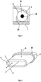
- Fig.4 shows detail A from Fig.4 , whereby the receiving groove 64 in which the sealing cord 6 is received can be clearly seen.
- the receiving groove 64 is formed on the first housing part 1 and provides a receiving space for the sealing cord 6.
- the receiving groove 64 comprises a groove base and two groove walls spaced apart in the longitudinal direction L, so that deformation of the sealing cord 6 in the longitudinal direction L and its displacement radially outwards are prevented.
- the receiving groove 64 only allows deformation of an inner cross section of the sealing cord 6 in the effective direction, namely in the radial direction.
- the sealing cord 6 rests with its sealing jacket 61 in a sealing manner on an outer circumference of the intake air line 9.
- the deformation and recovery capacity of the sealing cord is dimensioned such that it can reliably compensate for the relative movements between the two housing parts 1, 2 in the interface area 3 and can thus provide a secure and low-friction seal over the entire range of the relative position maxima of the housing parts 1, 2 to be expected during operation of the electric hand tool according to the invention.
- Fig.5 shows detail A from Fig.4 in an isometric view.
- the area of the seal of the intake air line 9 is opposite the first housing part (the first housing part and the receiving groove are not shown) shown schematically in an enlarged view by the intake air line seal 92 designed as a sealing cord 6.
- the sealing cord 6 bridges a radial gap between the groove base of the receiving groove 64 of the first housing part 1 and the intake air line 9 and lies sealingly against an outer circumference of the intake air line 9. This enables optimum relative freedom of movement of the intake air line 9 arranged on the second housing part 2 with respect to the first housing part 1, both in the longitudinal direction L and in the transverse direction Q.
- Fig.6 shows a detailed view of a sealing cord 6 of an electric hand tool 10 according to the invention.
- the sealing cord 6 comprises an elastic core 62, around which a sealing sheath 61 designed as a fiber sheath 61 is wound and/or braided.
- the sealing sheath 61 can also be coated, applied, foamed or otherwise attached to the core 62 in the form of a sheath.
- the elastic core 62 is designed to provide elastic restoring forces to achieve the sealing effect, so that the sealing cord 6 can reliably perform its sealing function over the entire service life of the electric hand tool 10.
- the elastic core 62 is hollow in the special embodiment shown.
- the sealing sheath 61 designed as a fiber sheath 61 is responsible for the desired sealing effect and the low frictional forces in the sealing contact.
- the fiber sheath 61 can in particular comprise several fiber layers wound and/or braided one on top of the other, which further improves the sealing effect.
- the sealing cord 6 can be purchased in the form of meter goods for use in an electric hand tool according to the invention, particularly with little effort and at low cost, and can be cut to the individually required length during production.
- the respective free ends of a sealing cord section can be connected to one another before installation in order to obtain a circumferentially closed sealing cord that allows a particularly effective full-circumference seal.
Landscapes
- Engineering & Computer Science (AREA)
- Mechanical Engineering (AREA)
- General Engineering & Computer Science (AREA)
- Portable Power Tools In General (AREA)
Abstract
Das erfindungsgemäße Elektrohandwerkzeug (10) weist zumindest zwei relativ zueinander beweglich gelagerte Geräteteile (1,2) auf, wobei ein erstes Geräteteil (1) eine Motor-Getriebeeinheit mit einer Werkzeugaufnahme umfasst und ein zweites Geräteteil (2) eine Griffeinheit umfasst. Das erste (1) und das zweite Geräteteil (2) sind über zumindest eine Vibrationsminderungsvorrichtung (4) miteinander gekoppelt und grenzen in einem Schnittstellenbereich (3) durch einen Luftspalt (31) beabstandet aneinander, wobei in dem Schnittstellenbereich (3) zumindest ein Dichtelement vorliegt, das eine Dichtschnur (6) aufweist, die einen elastischen Kern (62) sowie einen Dichtmantel (61) umfasst.
Description
- Die vorliegende Erfindung betrifft ein Elektrohandwerkzeug, insbesondere einen Bohrhammer.
- Bohrhämmer und andere Elektrohandwerkzeuge wie Bohrmaschinen, Säbelsägen, Kreissägen, Stichsägen, Kernbohrgeräte und/oder Abbruchhämmer (für Boden und Wände) werden fortwährend hinsichtlich Leistungs- und Gewichtsaspekten sowie Ergonomie weiter einwickelt. In puncto Ergonomie sind insbesondere die auf einen Anwender einwirkenden Vibrationsbelastungen ein Schwerpunkt der Entwicklungsanstrengungen. Unzulässig hohe Vibrationsbelastungen können, insbesondere bei Anwendern aus dem professionellen Bereich, schwere gesundheitliche Schäden, darunter die so genannte Weißfingerkrankheit, hervorrufen.
- Daher sind Bohrhämmer und andere Elektrohandwerkzeuge bekannt, bei denen zwischen Handgriff und Motor-Getriebeeinheit Vorrichtungen zur Vibrationsminderung angeordnet sind. Derartige Vibrationsminderungsvorrichtungen sind dazu ausgebildet, eine Minderung der am Handgriff auftretenden Vibrationsbelastung zu bewirken, indem die Weiterleitung von Vibrationen der Motor-Getriebeeinheit möglichst breitbandig reduziert wird. Der Handgriff und die Motor-Getriebeeinheit sind hierbei in der Regel zueinander beweglich gelagert, wobei Feder- und/oder Dämpferelemente sowie ggf. Gleitelemente eingesetzt werden, die auf ein im Betrieb erwartbares Vibrationsspektrum angepasst sind. Der erforderliche Bewegungsspielraum wird durch einen Luftspalt realisiert, der zwischen Handgriff und Motor-Getriebeeinheit vorliegt. Da im Bereich des Luftspalts im Betrieb Relativbewegungen zwischen Handgriff und Motor-Getriebeeinheit auftreten, ist der Luftspalt mit einem Eingriffsschutz versehen, wozu häufig eine Balgabdichtung zum Einsatz kommt, die den Luftspalt im Bereich der Schnittstelle zwischen Handgriff und Motor-Getriebeeinheit voll- oder zumindest teilumfänglich umläuft.
- Alternativ oder zusätzlich zu Feder und/oder Dämpferelementen zur Vibrationsentkopplung können in Elektrohandwerkzeugen auch Schwingungstilger zum Einsatz kommen, die in der Regel federnd gelagerte Gegengewichte aufweisen, um die im Betrieb betragsmäßig dominierenden Frequenzbereiche zu unterdrücken.
- Eine Balgabdichtung des Luftspalts gewährleistet zwar einen wirksamen Eingriffsschutz und stellt auch eine zuverlässige partielle oder vollständige fluidische oder mechanische Abdichtung des Schnittstellenbereichs bereit, ist jedoch aufgrund vergleichsweise hoher innerer und/oder äußerer Reibung relativ steif, sodass über eine Balgabdichtung in einem nicht unbeträchtlichen Maß Schwingungen von der Motor-Getriebeeinheit auf den Handgriff übertragen werden, was der angestrebten Wirkung der Vibrationsminderungsvorrichtung zuwider läuft.
- Aus dem Stand der Technik sind Elektrohandwerkzeuge mit Balgabdichtungen zur Schwingungsentkopplung von Vorrichtungsbestandteilen bekannt. Derartige Elektrohandwerkzeuge werden unter anderem in
DE 10 2006 060 652 A1 undEP 1 637 288 B1 beschrieben. - Ferner wird bei bekannten Elektrohandwerkzeugen, etwa bei Bohrhämmern, über den Schnittstellenbereich zwischen Handgriff und Motor-Getriebeeinheit häufig ein Kühlluftstrom angesaugt, der zum Thermomanagement der elektrischen, elektronischen und/oder mechanischen Komponenten des Elektrohandwerkzeugs benötigt wird. Aus diesem Grund muss die Abdichtung des Luftspalts nicht nur einen Eingriffsschutz bereitstellen, sondern zusätzlich auch möglichst fluiddicht sein. Eine Luftführung innerhalb des Schnittstellenbereichs ist dabei häufig derart realisiert, dass der Schnittstellenbereich beispielsweise durch ein Luftschott aus einem geschlossenzelligen Schaummaterial in einen Unterdruckbereich und einen Überdruckbereich unterteilt ist, um Bypassströmungen zwischen einer Saugseite und einer Druckseite eines Kühlluftgebläses zu verhindern. Ein derartiges Luftschott stellt eine weitere unerwünschte Schwingungskopplung zwischen Handgriff und Motor-Getriebeeinheit dar.
- Eine Aufgabe der vorliegenden Erfindung ist es daher, ein Elektrohandwerkzeug bereitzustellen, das sich durch eine verbesserte Schwingungsentkopplung des Handgriffs auszeichnet.
- Demgemäß wird ein Elektrohandwerkzeug, insbesondere ein Bohrhammer, vorgeschlagen, das zwei relativ zueinander beweglich gelagerte Geräteteile aufweist. Ein erstes Geräteteil umfasst eine Motor-Getriebeeinheit mit einer Werkzeugaufnahme und ein zweites Geräteteil eine Griffeinheit, wobei das erste und das zweite Geräteteil über zumindest eine Vibrationsminderungsvorrichtung miteinander gekoppelt sind und in einem Schnittstellenbereich durch einen Luftspalt beabstandet aneinander grenzen. In dem Schnittstellenbereich liegt zumindest ein Dichtelement vor, das eine Dichtschnur aufweist, die einen elastischen Kern sowie einen Dichtmantel umfasst.
- Der Einsatz einer Dichtschnur im Schnittstellenbereich hat gegenüber einer Balgabdichtung den Vorteil, dass diese im Funktionskontakt nur eine sehr geringe Reibung verursacht, sodass die Schwingungsentkopplung des zweiten Geräteteils mit der Griffeinheit hierdurch signifikant verbessert wird. Durch eine geeignete fachmännische Auslegung der Dichtschnur hinsichtlich Abmessungen, Steifigkeit, Materialien des elastischen Kerns sowie des Dichtmantels lässt sich zudem die erforderliche Dichtigkeit erreichen und ein Eindringen von Partikeln in den Schnittstellenbereich wirksam verhindern.
- Grundsätzlich gilt, dass sich für den Dichtmantel Kunststoffe mit guten Gleiteigenschaften besonders gut eignen. Der Dichtmantel kann als Vollmaterial oder in Form eines Fasergebildes vorliegen und den elastischen Kern außenliegend umgeben. Alternativ kann der Dichtmantel geschäumt sein, oder als dünner Film auf den elastischen Kern aufgetragen sein. Der elastische Kern stellt hierbei elastisch Rückstellkräfte bereit, die zur Erreichung einer Dichtwirkung unerlässlich sind, während der Dichtmantel für die eigentliche Abdichtungswirkung zuständig ist und selbst ein nur geringes Rückstellvermögen haben kann.
- Ein Querschnitt der Dichtschnur kann in einem nicht verformten Ausgangszustand etwa kreisförmig, ellipsenförmig oder polygonal sein.
- Die Dichtschnur kann insbesondere in einer Aufnahmenut des ersten und/oder zweiten Geräteteils aufgenommen sein. Die Aufnahmenut begrenzt die Verformung der Dichtschnur auf eine Wirkrichtung und kann bei einer Fertigung des ersten und/oder zweiten Geräteteils als Kunststoffspritzgußteil(e) kosten- und aufwandsneutral erzeugt werden.
- Gemäß einer vorteilhaften Weiterbildung kann der Dichtmantel der Dichtschnur ein Fasermantel sein, der um den elastischen Kern gewickelt und/oder geflochten ist, insbesondere kreuzförmig gewickelt und/oder geflochten. Alternativ kann der Dichtmantel jedoch auch auf den Kern beschichtet, aufgetragen, angeschäumt oder anderweitig mantelförmig auf dem Kern angebracht sein.
- Alternativ oder zusätzlich kann der elastische Kern hohl sein, wodurch einerseits Material eingespart werden kann und andererseits das Rückstellvermögen verbessert sowie die Dichtungsreaktionskräfte verringert werden können.
- Der Fasermantel der Dichtschnur kann eine Vielzahl insbesondere synthetischer Fasern aufweisen, wobei die Fasern insbesondere ein Polyamid, etwa ein Aramid, oder Polytetrafluorethylen umfassen oder daraus bestehen können. Die Erfindung ist jedoch ausdrücklich nicht auf vorgenannte Werkstoffe beschränkt, sondern umfasst auch andere, dem Fachmann geeignete Materialien, die vergleichbar vorteilhafte Gleit- und Dichteigenschaften besitzen.
- Der elastische Kern der Dichtschnur kann ein Elastomer, ein thermoplastisches Elastomer oder einen Kautschuk umfassen oder daraus bestehen, insbesondere ein Polyurethan oder ein Ethylen-Propylen-Dien-Kautschuk. Die Erfindung ist jedoch ausdrücklich nicht auf vorgenannte Werkstoffe beschränkt, sondern umfasst auch andere, dem Fachmann geeignete Materialien, die vergleichbar vorteilhafte Rückstelleigenschaften besitzen.
- Eine insbesondere geeignete Dichtschnur ist unter der Handelsmarke "Elastic Tankpak" des Herstellers EagleBurgmann Germany GmbH & Co. KG, 82515 Wolfratshausen (Deutschland) bekannt. Eine solche Dichtschnur in einem Durchmesserbereich von ca. 5 bis 20 mm ist optimal für das erfindungsgemäße Elektrohandwerkzeug geeignet.
- In einer bevorzugten Ausführungsform umfasst das Elektrohandwerkzeug ein Gehäuse mit einem ersten Gehäuseteil, das das erste Geräteteil bildet, und mit einem zweiten Gehäuseteil, das das zweite Geräteteil bildet. Gemäß dieser Ausführungsform liegt der Schnittstellenbereich daher zwischen zwei Teilen des Gehäuses vor, sodass durch die Dichtschnur zwei Gehäuseteile gegeneinander abgedichtet werden.
- In einer alternativen Ausführungsform umfasst das Elektrohandwerkzeug ein Sub-Chassis, das die Motor-Getriebeeinheit mit der Werkzeugaufnahme umfasst und das erste Geräteteil bildet, sowie ein Gehäuse, in dem das Sub-Chassis angeordnet ist und das das zweite Geräteteil bildet. Gemäß dieser Ausführungsform liegt der Schnittstellenbereich daher innerhalb des Gehäuses vor, wobei die Dichtschnur das Sub-Chassis gegenüber dem Gehäuse abdichtet. In diesem Fall kann das Gehäuse selbst ohne äußeren Luftspalt und/oder ohne eine Zweiteilung zwischen "Griff" und "Gerät" ausgeführt sein.
- Unter einem Sub-Chassis wird ein Vorrichtungsbestandteil des Elektrohandwerkzeugs verstanden, der die antriebsrelevanten Komponenten, beispielsweise Getriebe-/Antriebs-/Schlagwerkseinheit, aufweist und seinerseits gegenüber dem Gehäuse beweglich entkoppelt gelagert ist, wobei zur Entkopplung beispielsweise Federn, Gleitlager, Schaumstoffe oder dergleichen zum Einsatz kommen. Nach außen bildet das Gehäuse insbesondere eine Einheit und ist in sich unbeweglich bzw. stationär. Das Gehäuse bildet gemäß dieser Ausführungsform gewissermaßen eine Schalung, innerhalb der sich das Sub-Chassis entkoppelt gelagert bewegen kann, wodurch eine besonders wirksame Vibrationsentkopplung der antriebsrelevanten Komponenten erreicht wird und die Steifigkeit des Gehäuses erhöht werden kann.
- Gemäß einer weiteren Ausführungsform liegt innerhalb des Gehäuses eine Fluidführungsanordnung, insbesondere Luftführungsanordnung, vor, die einen insbesondere mit der Motor-Getriebeeinheit gekoppelten Luftstromerzeuger - etwa ein Kühlluftgebläse - umfasst. Die Fluidführungsanordnung, insbesondere Luftführungsanordnung, weist einen Ansaugfluidpfad, insbesondere Ansaugluftpfad, auf, der zumindest abschnittsweise durch den Schnittstellenbereich verläuft. Damit stellt die Fluidführungsanordnung, insbesondere Luftführungsanordnung, ein Kühlsystem dar, über das das Thermomanagement der elektrischen, elektronischen und/oder mechanischen Komponenten des Elektrohandwerkzeugs realisiert wird um Überhitzung zu vermeiden und im Betrieb des Elektrohandwerkzeugs anfallende Wärmelasten nach außerhalb des Gehäuses abzuführen. Da der Ansaugfluidpfad, insbesondere Ansaugluftpfad, zumindest abschnittsweise durch den Schnittstellenbereich verläuft, ist die Dichtschnur im Bereich des Schnittstellenbereichs an der Abdichtung des Ansaugfluidpfads, insbesondere Ansaugluftpfads, beteiligt.
- In Ausführungsformen ist es auch möglich, dass die Fluidführungsanordnung einen Abluftpfad aufweist, der zumindest abschnittsweise durch den Schnittstellenbereich verläuft, sodass die Dichtschnur im Bereich des Schnittstellenbereichs dann an der Abdichtung eine solchen Abluftpfads beteiligt ist.
- Bei Ausführungen, die ein Sub-Chassis umfassen kann die Dichtschnur ferner vorteilhaft dazu eingerichtet sein, einen Ansaugluftpfad von einem Abluftpfad zu trennen.
- In Ausführungen kann die Luftführungsanordnung zumindest eine Ansaugöffnung in dem Gehäuse umfassen, die fluidisch mit dem Ansaugluftpfad verbunden ist. Genauer liegt die Ansaugöffnung stromaufwärts des Schnittstellenbereichs vor. Insbesondere kann die Ansaugöffnung in dem zweiten Gehäuseteil vorliegen.
- Ferner kann in Ausführungen innerhalb des Gehäuses eine operativ mit der Motor-Getriebeeinheit gekoppelte Elektronikbaugruppe vorliegen, die zumindest abschnittsweise in dem Ansaugfluidpfad, insbesondere Ansaugluftpfad, liegt. Insbesondere kann die Elektronikbaugruppe in dem zweiten Gehäuseteil vorliegen. Die Elektronikbaugruppe ist hierbei in einem Betriebszustand des Elektrohandwerkzeugs von einem durch den Ansaugfluidpfad, insbesondere Ansaugluftpfad, geführten Luftstrom, insbesondere Kühlluftstrom, überstreichbar, sodass in der Elektronikbaugruppe entstehende Wärmelasten wirksam abgeführt werden können. Die Elektronikbaugruppe kann beispielsweise einen Schalter, eine Steuerungs- und/oder Regelungsvorrichtung, insbesondere umfassend Leistungselektronik, aufweisen. Die Elektronikbaugruppe kann zumindest einen Kühlkörper aufweisen, um einen Wärmeübertrag auf den Kühlluftstrom zu verbessern. In einer besonderen Ausführungsform kann die Elektronikbaugruppe in einem so genannten entkoppelten Handgriff angeordnet sein.
- Gemäß einer noch weiteren Ausführungsform kann in dem Schnittstellenbereich ein Unterdruckbereich, aufweisend einen Abschnitt des Ansaugfluidpfads, insbesondere Ansaugluftpfads, sowie ein Überdruckbereich vorliegen. Der Überdruckbereich kann hierbei einen Abschnitt eines Druckluftpfads aufweisen. Der Unterdruckbereich und der Überdruckbereich sind hierbei durch ein Luftschott getrennt. Das Luftschott kann eine Dichtschnur umfassen, die einen elastischen Kern sowie einen Dichtmantel aufweist. Der Unterdruckbereich befindet sich insbesondere an einer Saugseite des Luftstromerzeugers während der Überdruckbereich an einer Druckseite des Luftstromerzeugers vorliegt.
- Indem das Luftschott mit einer Dichtschnur anstelle des im Stand der Technik gebräuchlichen geschlossenzelligen Schaummaterials ausgeführt wird, kann die Schwingungsentkopplung des zweiten Geräteteils, insbesondere des zweiten Gehäuseteils, mit der Griffeinheit noch weiter verbessert werden. Die Dichtschnur des Luftschotts kann hierbei entweder an dem ersten Geräteteil oder an dem zweiten Geräteteil angeordnet sein, wobei das jeweils andere Geräteteil eine korrespondierende Kontaktfläche bereitstellt, mit der die Dichtschnur in Dichtkontakt steht.
- Alternativ oder zusätzlich kann in dem Schnittstellenbereich eine Umfangsdichtung vorliegen, die das erste und das zweite Geräteteil zumindest teilumfänglich, insbesondere jedoch vollumfänglich, gegeneinander abdichtet, wobei insbesondere die Umfangsdichtung eine Dichtschnur aufweist, die einen elastischen Kern sowie einen Dichtmantel umfasst.
- Insbesondere dichtet die Umfangsdichtung das erste und das zweite Gehäuseteil zumindest teilumfänglich, insbesondere jedoch vollumfänglich, gegeneinander ab.
- Eine als Dichtschnur ausgeführte Umfangsdichtung im Schnittstellenbereich hat eine deutlich geringere Reibung als die im Stand der Technik übliche Balgabdichtung, sodass die Schwingungsentkopplung des zweiten Geräteteils mit der Griffeinheit noch weiter verbessert werden kann.
- In Ausführungen kann im Schnittstellenbereich ergänzend ein Übergriffsbereich vorgesehen sein, der sich über den Luftspalt hinweg von einem Geräteteil zu dem anderen Geräteteil erstreckt und die Dichtschnur hierbei überlappt, sodass diese vor direkten externen mechanischen Einwirkungen geschützt ist und der Eingriffsschutz verbessert ist. Zudem fungiert ein derartiger Übergriffsbereich gewissermaßen als Labyrinthdichtung, sodass die Dichtwirkung der Dichtschnur hierdurch weiter verbessert werden kann. Der Übergriffsbereich kann als ein an einem Geräteteil ausgebildeter, den Schnittstellenbereich umlaufender Kragen ausgebildet sein, der sich zu dem anderen Geräteteil erstreckt, wobei das andere Geräteteil in einem von dem Kragen umschlossenen Bereich aufgenommen ist. Die Dichtschnur der Umfangsdichtung kann hierbei entweder an dem ersten Geräteteil oder an dem zweiten Geräteteil angeordnet sein, wobei das jeweils andere Geräteteil eine korrespondierende Kontaktfläche bereitstellt, mit der die Dichtschnur in Dichtkontakt steht.
- In einer weiteren Ausführungsform kann die Fluidführungsanordnung, insbesondere Luftführungsanordnung, zumindest eine Ansaugluftleitung aufweisen, die sich in dem Schnittstellenbereich zumindest abschnittsweise von dem ersten in das zweite Geräteteil oder von dem zweiten in das erste Geräteteil erstreckt und dabei den Luftspalt überbrückt. Durch die Ansaugluftleitung verläuft ein Abschnitt des Ansaugfluidpfads, insbesondere Ansaugluftpfads. Bevorzugt ist die Ansaugluftleitung gegenüber dem Geräteteil, in das diese sich erstreckt, durch eine Dichtschnur abgedichtet, die einen elastischen Kern sowie einen Dichtmantel umfasst.
- Vorteilhafterweise liegt der Luftspalt des Schnittstellenbereichs gemäß dieser Ausführungsform nicht im Ansaugfluidpfads, insbesondere Ansaugluftpfad, sodass eine Trennung des Schnittstellenbereichs in Unterdruckbereich und Überdruckbereich nicht erforderlich ist und in der Folge das Luftschott entfallen kann. Gemäß dieser Ausführungsform ist daher der positive Effekt auf die Schwingungsentkopplung des zweiten Geräteteils umfassend die Griffeinheit maximiert.
- Für alle hierin beschriebenen möglichen Anordnungen bzw. Einsatzzwecke der Dichtschnur im Schnittstellenbereich gilt, dass der Dichtkontakt insbesondere radial erfolgen kann.
- In Ausführungen kann das zweite Geräteteil zumindest entlang einer Werkzeugachse der Motor-Getriebeeinheit gegenüber dem ersten Geräteteil beweglich gelagert sein. Insbesondere kann die Werkezugachse eine Längsachse des Elektrohandwerkzeugs sein, sodass das zweite Geräteteil zumindest mit einer Bewegungskomponente in oder parallel zur Längsachse gegenüber dem ersten Geräteteil beweglich ist. Die Beweglichkeit des zweiten Geräteteil gegenüber dem ersten Geräteteil kann aber auch eine Komponente quer zur Längsachse umfassen, wenn auch mit einem geringeren Betrag. In Ausführungen umfassend ein Sub-Chassis, das das erste Geräteteil bildet, kann das erste Geräteteil zumindest entlang einer Werkzeugachse der Motor-Getriebeeinheit gegenüber dem Gehäuse, das das zweite Geräteteil bildet, beweglich gelagert sein.
- In Ausführungen kann die Vibrationsminderungsvorrichtung zumindest ein Federelement umfassen, das sich einenends an dem ersten Geräteteil und anderenends an dem zweiten Geräteteil abstützt. Die Abstützung des Federelements an den Geräteteilen kann unmittelbar oder mittelbar erfolgen, sprich unter Zwischenschaltung von zusätzlichen Vorrichtungsbestandteilen, die einen Kraftfluss zum respektive vom Federelement leiten.
- Das zumindest ein Federelement kann sich beispielsweise entlang der Werkzeugachse der Motor-Getriebeeinheit erstrecken. In Ausführungen handelt es sich bei dem Federelement um eine Druckfeder, insbesondere eine Schraubenfeder. In anderen Ausführungen kann das Federelement aber auch als Torsionsfeder ausgebildet sein. Das Federelement kann alternativ oder zusätzlich einen Schaumstoff aufweisen oder daraus bestehen.
- Ferner kann die Vibrationsminderungsvorrichtung zumindest ein Dämpfungselement umfassen, das sich einenends an dem ersten Geräteteil und anderenends an dem zweiten Geräteteil abstützt. Das Dämpfungselement ist dazu ausgebildet, vom Federelement aufgenommene Bewegungsenergie zu dissipieren, sodass ein unkontrolliertes Aufschwingen vermieden werden kann,
- In Ausführungen kann das zweite Geräteteil, insbesondere das zweite Gehäuseteil, über zumindest ein Gelenk schwenkbar an dem ersten Geräteteil, insbesondere dem ersten Gehäuseteil, gelagert sein, wobei insbesondere das Gelenk das Dämpfungselement, insbesondere in Form eines Rotationsdämpfungselements, umfasst. Das Rotationsdämpfungselement kann insbesondere ein Kunststoffmaterial aufweisen oder daraus bestehen, wobei das Kunststoffmaterial insbesondere eine hohe innere Dämpfung bereitstellen kann.
- Gemäß einer noch weiteren Ausführungsform kann zumindest ein Bestandteil der Vibrationsminderungsvorrichtung in dem Schnittstellenbereich vorliegen. Insbesondere kann das zumindest eine Federelement und/oder das zumindest eine Dämpfungselement der Vibrationsminderungsvorrichtung in dem Schnittstellenbereich vorliegen. Alternativ kann eine mit dem zumindest einen Federelement und/oder dem zumindest einen Dämpfungselement der Vibrationsminderungsvorrichtung verbundene Kraftleitstruktur in dem Schnittstellenbereich vorliegen.
- Die nachfolgende Beschreibung erläutert die Erfindung anhand von exemplarischen Ausführungsformen und Figuren. In den Figuren zeigt:
- Fig. 1
- eine schematische Längsschnittansicht eines erfindungsgemäßen Elektrohandwerkzeugs gemäß einer ersten Ausführungsform;
- Fig. 2
- eine schematische Längsschnittansicht eines erfindungsgemäßen Elektrohandwerkzeugs gemäß einer zweiten Ausführungsform;
- Fig. 3
- eine schematische Längsschnittansicht eines erfindungsgemäßen Elektrohandwerkzeugs gemäß einer dritten Ausführungsform;
- Fig. 4
- Detail A aus
Fig. 4 ; - Fig. 5
- Detail A aus
Fig. 4 in einer isometrischen Ansicht; und - Fig. 6
- Detailansicht einer Dichtschnur eines erfindungsgemäßen Elektrohandwerkzeugs.
- Gleiche oder funktionsgleiche Elemente werden durch gleiche Bezugszeichen in den Figuren indiziert, soweit nichts anderes angegeben ist.
-
Fig. 1 zeigt ein erfindungsgemäßes Elektrohandwerkzeug 10 in Form eines Bohrhammers 10 in einer ersten Ausführungsform in einem schematischen Längsschnitt. Der Bohrhammer 10 weist ein Gehäuse und zwei relativ zueinander beweglich gelagerte Geräteteile 1,2 auf. Ein erstes Geräteteil 1 ist als erstes Gehäuseteil 1 umfassend eine Motor-Getriebeeinheit mit einer Werkzeugaufnahme (nicht dargestellt) ausgebildet. Ein zweites Geräteteil 2 ist als zweites Gehäuseteil 2 umfassend eine Griffeinheit ausgebildet. - In der folgenden Beschreibung der Figuren wird für die Geräteteile 1,2 durchgängig der Begriff Gehäuseteile 1,2 verwendet, was die Erfindung jedoch explizit nicht hierauf einschränkt und lediglich einem besseren Verständnis der Ausführungsformen dient.
- Das erste Gehäuseteil 1 und das zweite Gehäuseteil 2 sind über eine Vibrationsminderungsvorrichtung 4 miteinander gekoppelt und grenzen in einem Schnittstellenbereich 3 durch einen Luftspalt 31 beabstandet aneinander. Die Vibrationsminderungsvorrichtung 4 umfasst zumindest ein Druckfederelement 41, über das das zweite Gehäuseteil 2 federnd gegenüber dem ersten Gehäuseteil 1 gelagert ist. Ferner umfasst die Vibrationsminderungsvorrichtung 4 ein Dämpfungselement 42, welches als Rotationsdämpfungselement ausgeführt ist und in ein Gelenk 43 integriert ist, welches das zweite Gehäuseteil 2 schwenkbar mit dem ersten Gehäuseteil 1 koppelt. Das zweite Gehäuseteil 2 ist mittels des Gelenks 43 um den Drehpunkt 431 gegenüber dem ersten Gehäuseteil 1 schwenkbar. Folglich erlaubt die Vibrationsminderungsvorrichtung 4 einen Bewegungsfreiheitsgrad des zweiten Gehäuseteils 2 gegenüber dem ersten Gehäuseteil 1 zumindest entlang der Werkzeugachse bzw. Längsachse L des Elektrohandwerkzeugs 10, genauer eine Kipp-/Nickbewegung um den Drehpunkt 431.
- Innerhalb des Gehäuses ist eine Luftführungsanordnung ausgebildet, die einen (nicht dargestellten) mit der (ebenfalls nicht dargestellten) Motor-Getriebeeinheit gekoppelten Luftstromerzeuger (ebenfalls nicht dargestellt) umfasst. Die Luftführungsanordnung umfasst einen Ansaugluftpfad C, der abschnittsweise durch den Schnittstellenbereich 3 verläuft. Mit anderen Worten erfolgt die Bereitstellung von Kühlluft durch den Ansaugluftpfad C durch den Schnittstellenbereich 3 bzw. den Luftspalt 31. Die Luftführungsanordnung stellt ein Kühlluftsystem dar, über das das Thermomanagement der elektrischen, elektronischen und/oder mechanischen Komponenten des Elektrohandwerkzeugs 10 realisiert wird um Überhitzung zu vermeiden und im Betrieb des Elektrohandwerkzeugs 10 anfallende Wärmelasten nach außerhalb des Gehäuses abzuführen.
- Die Luftführungsanordnung bezieht die Kühlluft von außerhalb des Gehäuses, nämlich durch Ansaugöffnungen 21 in dem zweiten Gehäuseteil 2, die fluidisch mit dem Ansaugluftpfad C verbunden sind und sich stromaufwärts des Schnittstellenbereichs 3 befinden.
- Der Schnittstellenbereich 3 ist durch ein Luftschott 32 in einen Unterdruckbereich 34, aufweisend einen Abschnitt des Ansaugluftpfads C, sowie einen Überdruckbereich 33 getrennt, um Bypassströmungen zwischen einer Saugseite und einer Druckseite des Luftstromerzeugers, beispielsweise umfassend ein Kühlluftgebläse, zu vermeiden. Der Unterdruckbereich 34 ist hierbei mit einer Saugseite des Luftstromerzeugers verbunden während der Überdruckbereich 33 mit einer Druckseite des Luftstromerzeugers verbunden ist. Das Luftschott 32 ist gemäß der ersten Ausführungsform aus einem insbesondere geschlossenzelligen Schaummaterial gebildet.
- Um eine möglichst reibungsarme Abdichtung der beiden Gehäuseteile 1,2 im Schnittstellenbereich 3 zu erreichen, liegt im Schnittstellenbereich 3 eine Umfangsdichtung 5 vor, die die beiden Gehäuseteile 1,2 vollumfänglich gegeneinander abdichtet, wobei die Umfangsdichtung 5 eine Dichtschnur 6 aufweist. Hierdurch kann einerseits eine sichere Abdichtung des durch den Schnittstellenbereich 3 verlaufenden Abschnitts des Ansaugluftpfads C bzw. eines druckseitigen Abschnitts des Kühlluftpfads erreicht werden. Andererseits wird die Schwingungsentkopplung des zweiten Gehäuseteils 2 durch die sehr reibungsarme Dichtschnur 6 optimiert.
- Um zu verhindern, dass größere Fremdkörper oder Körperteile wie Finger in den Schnittstellenbereich 3 gelangen, ist im Schnittstellenbereich 3 ein Übergriffsbereich 8 vorgesehen, der sich über den Luftspalt 31 hinweg vom ersten Gehäuseteil 1 zum zweiten Gehäuseteil 2 erstreckt und die Dichtschnur 6 überlappt, sodass diese vor direkten externen mechanischen Einwirkungen geschützt ist. Zudem fungiert der Übergriffsbereich 8 als Labyrinthdichtung, was die Dichtwirkung der Dichtschnur 6 weiter verbessert. Der Übergriffsbereich 8 ist als ein an dem ersten Gehäuseteil 1 ausgebildeter, den Schnittstellenbereich 3 umlaufender Kragen ausgebildet, der sich zum zweiten Gehäuseteil 2 erstreckt, wobei das zweite Gehäuseteil 2 in einem von dem Kragen umschlossenen Bereich aufgenommen ist. Die Dichtschnur 6 der Umfangsdichtung 5 ist hierbei an dem ersten Gehäuseteil 1 gehalten. Das zweite Gehäuseteil 2 stellt an seinem Außenumfang eine korrespondierende Kontaktfläche bereit, mit der die Dichtschnur 6 in Dichtkontakt steht. Konkret ist die Dichtschnur 6 in einer an dem ersten Gehäuseteil 1 vorliegenden Aufnahmenut 64 angeordnet, wobei die Aufnahmenut 64 insbesondere an dem Kragen des Übergriffsabschnitts 8 ausgebildet ist. Die Dichtschnur 6 der Umfangsdichtung 5 wirkt radial.
- Das Elektrohandwerkzeug 10 weist ferner an seinem zweiten Gehäuseteil 2 umfassend die Griffeinheit einen Handgriff 23 sowie ein elektrisches Anschlusskabel 22 auf, das die zum Betrieb der Motor-Getriebeeinheit nötige Energie liefert. In einer nicht figurativ gezeigten Ausführungsform kann das Elektrohandwerkzeug 10 auch als Akkugerät ausgeführt sein und einen elektrischen Energiespeicher aufweisen.
- Das in
Fig. 2 dargestellte erfindungsgemäße Elektrohandwerkzeug 10 gemäß einer zweiten Ausführungsform unterscheidet sich von der ersten Ausführungsform dadurch, dass das Luftschott 32 nicht durch ein Schaummaterial gebildet ist, sondern ebenfalls eine Dichtschnur 6 umfasst. Das Luftschott 32 umfasst eine erste, dem ersten Gehäuseteil 1 zugeordnete Trennwand 321 sowie eine zweite, dem zweiten Gehäuseteil 2 zugeordnete Trennwand 322. Die erste Trennwand 321 und die zweite Trennwand 322 überlappen einander in Längsrichtung L teilweise und sind in Querrichtung zueinander beabstandet. Die zweite Trennwand 322 trägt eine Dichtschnur 6, die mit der ersten Trennwand 321 in dichtendem Kontakt stehen. In einer nicht dargestellten Ausführungsform kann die Dichtschnur 6 jedoch auch an der ersten Trennwand 321 vorliegen. Da ein aus Schaummaterial gefertigtes Luftschott 32 in erheblichem Maße Schwingungen vom ersten 1 auf das zweite Gehäuseteil 2 überträgt, kann durch die Ausführung des Luftschotts 32 mit einer Dichtschnur 6 die Schwingungsentkopplung des zweiten Gehäuseteils 2 mit der Griffeinheit noch weiter verbessert werden. - Das in
Fig. 3 in einem schematischen Längsschnitt dargestellte Elektrohandwerkzeug 10 in Form eines Bohrhammers 10 gemäß einer dritten Ausführungsform unterscheidet sich von den ersten beiden Ausführungsformen maßgeblich durch eine unterschiedliche Luftführung des Ansaugluftpfads C der Luftführungsanordnung. Der Schnittstellenbereich 3 liegt hierbei nicht im Ansaugluftpfad C, sondern wird gewissermaßen überbrückt. Die Ansaugung der Kühlluft des Ansaugluftpfads C erfolgt weiterhin durch in dem zweiten Gehäuseteil 2 vorgesehene Ansaugöffnungen 21. Jedoch weist die Luftführungsanordnung eine Ansaugluftleitung 9 auf, durch die ein Abschnitt des Ansaugluftpfads C verläuft. Die Ansaugluftleitung 9 erstreckt sich in dem Schnittstellenbereich 3 zumindest abschnittsweise von dem zweiten Gehäuseteil 2 in das erste Gehäuseteil 1 und überbrückt dabei den Luftspalt 31. Genauer erstreckt sich die Ansaugluftleitung 9 auf einem Eintauchabschnitt 91 von dem zweiten Gehäuseteil 2 in das erste Gehäuseteil 1. Die Ansaugluftleitung 9 ist über eine Ansaugluftleitungsdichtung 92 gegenüber dem ersten Gehäuseteil 1 abgedichtet, wobei die Ansaugluftleitungsdichtung 92 eine Dichtschnur 6 umfasst. Die Dichtschnur 6 der Ansaugluftleitungsdichtung 92 ist als radial wirksame Dichtschnur 6 ausgebildet, um die im Schnittstellenbereich 3 auftretenden Relativbewegungen der beiden Gehäuseteile 1,2 optimal ausgleichen zu können. Da der Luftspalt 31 des Schnittstellenbereichs 3 gemäß dieser Ausführungsform nicht im Ansaugluftpfad C liegt, ist eine Trennung des Schnittstellenbereichs 3 in Unterdruckbereich und Überdruckbereich nicht erforderlich, sodass in der Folge das Luftschott entfallen kann. Gemäß dieser Ausführungsform ist daher der positive Effekt auf die Schwingungsentkopplung des zweiten Gehäuseteils 2 umfassend die Griffeinheit maximiert. - Der Ansaugluftpfad C verläuft im zweiten Gehäuseteil 2 umfassend die Griffeinheit über eine operativ mit der Motor-Getriebeeinheit gekoppelte Elektronikbaugruppe 7, die in der Griffeinheit angeordnet sein kann. Die Elektronikbaugruppe 7 wird in einem Betriebszustand des Elektrohandwerkzeugs 10 von einem durch den Ansaugluftpfad C geführten Kühlluftstrom überstrichen, sodass in der Elektronikbaugruppe 7 entstehende Wärmelasten wirksam abgeführt werden können.
-
Fig. 4 zeigt Detail A ausFig. 4 , wobei insbesondere die Aufnahmenut 64, in der die Dichtschnur 6 aufgenommen ist, gut zu erkennen ist. Die Aufnahmenut 64 ist am ersten Gehäuseteil 1 ausgebildet und stellt einen Aufnahmeraum für die Dichtschnur 6 bereit. Die Aufnahmenut 64 umfasst einen Nutgrund sowie zwei in Längsrichtung L beabstandete Nutwände, sodass eine Verformung der Dichtschnur 6 in Längsrichtung L sowie deren Verlagerung nach radial außen unterbunden ist. Die Aufnahmenut 64 lässt ausschließlich eine Verformung eines Innenquerschnitts der Dichtschnur 6 in Wirkrichtung, nämlich in Radialrichtung, zu. Die Dichtschnur 6 liegt mit Ihrem Dichtmantel 61 dichtend an einem Außenumfang der Ansaugluftleitung 9 an. Das Verformungs- und Rückstellvermögen der Dichtschnur ist dabei so bemessen, dass diese die Relativbewegungen zwischen den beiden Gehäuseteilen 1,2 im Schnittstellenbereich 3 zuverlässig kompensieren kann und so über den gesamten Bereich der im Betrieb des erfindungsgemäßen Elektrohandwerkzeugs zu erwartenden relativen Lagemaxima der Gehäuseteile 1,2 eine sichere und reibungsarme Abdichtung bereitstellen kann. -
Fig. 5 zeigt Detail A ausFig. 4 in einer isometrischen Ansicht. Hierbei ist der Bereich der Abdichtung der Ansaugluftleitung 9 gegenüber dem ersten Gehäuseteil (das erste Gehäuseteil sowie die Aufnahmenut sind nicht gezeigt)
durch die als Dichtschnur 6 ausgeführte Ansaugluftleitungsdichtung 92 in vergrößerter Ansicht schematisch dargestellt. Die Dichtschnur 6 überbrückt einen Radialspalt zwischen dem Nutgrund der Aufnahmenut 64 des ersten Gehäuseteils 1 und der Ansaugluftleitung 9 und liegt dichtend an einem Außenumfang der Ansaugluftleitung 9 an. Dies ermöglicht eine optimale relative Bewegungsfreiheit der am zweiten Gehäuseteil 2 angeordneten Ansaugluftleitung 9 gegenüber dem ersten Gehäuseteil 1, sowohl in Längsrichtung L als auch in Querrichtung Q. -
Fig. 6 zeigt eine Detailansicht einer Dichtschnur 6 eines erfindungsgemäßen Elektrohandwerkzeugs 10. Die Dichtschnur 6 umfasst einen elastischen Kern 62, um den ein als Fasermantel 61 ausgebildeter Dichtmantel 61 gewickelt und/oder geflochten ist. In einer nicht figurativ gezeigten Ausführungsform kann der Dichtmantel 61 jedoch auch auf den Kern 62 beschichtet, aufgetragen, angeschäumt oder anderweitig mantelförmig auf dem Kern 62 angebracht sein. Der elastische Kern 62 ist dazu ausgebildet, elastisch Rückstellkräfte zur Erreichung der Dichtwirkung bereitzustellen, sodass die Dichtschnur 6 ihre Dichtfunktion zuverlässig über die gesamte Lebensdauer des Elektrohandwerkzeugs 10 ausüben kann. Der elastische Kern 62 ist in der gezeigten besonderen Ausführungsform hohl. Der als Fasermantel 61 ausgebildete Dichtmantel 61 ist für die angestrebte Abdichtungswirkung und die geringen Reibkräfte im Dichtkontakt verantwortlich. Der Fasermantel 61 kann insbesondere mehrere übereinander gewickelte und/oder geflochtene Faserlagen umfassen, was die Dichtwirkung weiter verbessert. Die Dichtschnur 6 kann zum Einsatz in einem erfindungsgemäßen Elektrohandwerkzeug insbesondere aufwands- und kostengünstig in Form von Meterware beschafft werden und in der Produktion auf das individuell erforderliche Längenmaß beschnitten werden. In Ausführungen können die jeweiligen freien Enden eines Dichtschnur-Abschnitts vor dem Verbau miteinander verbunden werden um eine umfänglich geschlossene Dichtschnur zu erhalten, die eine besonders wirksame vollumfängliche Abdichtung erlaubt. -
- 10
- Elektrohandwerkzeug / Bohrhammer
- 1
- Erstes Geräteteil/Gehäuseteil mit Motor-Getriebeeinheit
- 2
- Zweites Geräteteil/Gehäuseteil mit Griffeinheit
- 21
- Ansaugöffnung
- 22
- Anschlusskabel
- 23
- Handgriff
- 3
- Schnittstellenbereich
- 31
- Luftspalt
- 32
- Luftschott
- 321
- Trennwand
- 322
- Trennwand
- 33
- Überdruckbereich
- 34
- Unterdruckbereich
- 4
- Vibrationsminderungsvorrichtung
- 41
- Federelement
- 42
- Dämpfungselement / Rotationsdämpfungselement
- 43
- Gelenk
- 431
- Drehpunkt
- 5
- Umfangsdichtung
- 6
- Dichtschnur
- 61
- Dichtmantel / Fasermantel
- 62
- elastischer Kern
- 64
- Aufnahmenut
- 7
- Elektronikbaugruppe
- 8
- Übergriffsabschnitt
- 9
- Ansaugluftleitung
- 91
- Eintauchabschnitt
- 92
- Ansaugluftleitungsdichtung
- L
- Längsachse / Werkzeugachse
- Q
- Querrichtung
- C
- Ansaugfluidpfad/Ansaugluftpfad
Claims (15)
- Elektrohandwerkzeug (10), insbesondere Bohrhammer (10), aufweisend zwei relativ zueinander beweglich gelagerte Geräteteile (1,2), wobei ein erstes Geräteteil (1) eine Motor-Getriebeeinheit mit einer Werkzeugaufnahme umfasst und ein zweites Geräteteil (2) eine Griffeinheit umfasst, wobei das erste (1) und das zweite Geräteteil (2) über zumindest eine Vibrationsminderungsvorrichtung (4) miteinander gekoppelt sind und in einem Schnittstellenbereich (3) durch einen Luftspalt (31) beabstandet aneinander grenzen, wobei in dem Schnittstellenbereich (3) zumindest ein Dichtelement vorliegt,
dadurch gekennzeichnet, dass
das Dichtelement eine Dichtschnur (6) aufweist, die einen elastischen Kern (62) sowie einen Dichtmantel (61) umfasst. - Elektrohandwerkzeug (10) nach Anspruch 1, umfassend ein Gehäuse mit einem ersten Gehäuseteil (1), das das erste Geräteteil (1) bildet, und mit einem zweiten Gehäuseteil (2), das das zweite Geräteteil (2) bildet.
- Elektrohandwerkzeug (10) nach Anspruch 1, umfassend ein Sub-Chassis, das die Motor-Getriebeeinheit mit der Werkzeugaufnahme umfasst und das erste Geräteteil (1) bildet, sowie ein Gehäuse, in dem das Sub-Chassis angeordnet ist und das zweite Geräteteil (2) bildet.
- Elektrohandwerkzeug (10) nach Anspruch 2 oder 3, wobei innerhalb des Gehäuses eine Fluidführungsanordnung, insbesondere Luftführungsanordnung, vorliegt, die einen insbesondere mit der Motor-Getriebeeinheit gekoppelten Luftstromerzeuger umfasst, wobei die Fluidführungsanordnung, insbesondere Luftführungsanordnung, einen Ansaugfluidpfad (C), insbesondere Ansaugluftpfad (C), umfasst, der zumindest abschnittsweise durch den Schnittstellenbereich (3) verläuft.
- Elektrohandwerkzeug (10) nach Anspruch 4, wobei die Fluidführungsanordnung, insbesondere Luftführungsanordnung, zumindest eine Ansaugöffnung (21) in dem Gehäuse umfasst, die fluidisch mit dem Ansaugfluidpfad (C), insbesondere Ansaugluftpfad (C), verbunden ist, wobei die Ansaugöffnung (21) stromaufwärts des Schnittstellenbereichs (3) vorliegt.
- Elektrohandwerkzeug (10) nach Anspruch 4 oder 5, wobei in dem Gehäuse eine operativ mit der Motor-Getriebeeinheit gekoppelte Elektronikbaugruppe (7) vorliegt, die zumindest abschnittsweise in dem Ansaugfluidpfad (C) liegt.
- Elektrohandwerkzeug (10) nach einem der Ansprüche 4 bis 6, wobei in dem Schnittstellenbereich (3) ein Unterdruckbereich (34), aufweisend einen Abschnitt des Ansaugfluidpfads (C), sowie ein Überdruckbereich (33) vorliegt, die durch ein Luftschott (32) getrennt sind, wobei insbesondere das Luftschott (32) eine Dichtschnur (6) aufweist, die einen elastischen Kern (62) sowie einen Dichtmantel (61) umfasst.
- Elektrohandwerkzeug (10) nach einem der vorigen Ansprüche, wobei in dem Schnittstellenbereich (3) eine Umfangsdichtung (5) vorliegt, die das erste (1) und das zweite Geräteteil (2) zumindest teilumfänglich gegeneinander abdichtet, wobei insbesondere die Umfangsdichtung (5) eine Dichtschnur (6) aufweist, die einen elastischen Kern (62) sowie einen Dichtmantel (61) umfasst.
- Elektrohandwerkzeug (10) nach einem der Ansprüche 2 bis 6, wobei die Fluidführungsanordnung zumindest eine Ansaugluftleitung (9) aufweist, die sich in dem Schnittstellenbereich (3) zumindest abschnittsweise von dem ersten (1) in das zweite Geräteteil (2) oder von dem zweiten (2) in das erste Geräteteil (1) erstreckt und dabei den Luftspalt (31) überbrückt, wobei durch die Ansaugluftleitung (9) ein Abschnitt des Ansaugfluidpfads (C) verläuft, wobei insbesondere die Ansaugluftleitung (9) gegenüber dem Geräteteil (1,2), in das diese sich erstreckt, durch eine Dichtschnur (6) abgedichtet ist, die einen elastischen Kern (62) sowie einen Dichtmantel (61) umfasst.
- Elektrohandwerkzeug (10) nach einem der vorigen Ansprüche, wobei das zweite Geräteteil (2) zumindest entlang einer Werkzeugachse (L) der Motor-Getriebeeinheit gegenüber dem ersten Geräteteil (1) beweglich gelagert ist.
- Elektrohandwerkzeug (10) nach einem der vorigen Ansprüche, wobei das zweite Geräteteil (2) über zumindest ein Gelenk (43) schwenkbar an dem ersten Geräteteil (1) gelagert ist, wobei das Gelenk (43) insbesondere das Dämpfungselement (42), insbesondere ein Rotationsdämpfungselement (42), umfasst.
- Elektrohandwerkzeug (10) nach einem der vorigen Ansprüche, wobei zumindest ein Bestandteil der Vibrationsminderungsvorrichtung (4) in dem Schnittstellenbereich (3) vorliegt, insbesondere wobei das zumindest eine Federelement (41) und/oder das zumindest eine Dämpfungselement (42) der Vibrationsminderungsvorrichtung (4) oder eine mit dem zumindest einen Federelement (41) und/oder dem zumindest einen Dämpfungselement (42) der Vibrationsminderungsvorrichtung (4) verbundene Kraftleitstruktur in dem Schnittstellenbereich (3) vorliegt.
- Elektrohandwerkzeug (10) nach einem der vorigen Ansprüche, wobei der Dichtmantel (61) der Dichtschnur (6) ein Fasermantel (61) ist, der um den elastischen Kern (62) gewickelt und/oder geflochten ist, insbesondere kreuzförmig gewickelt und/oder geflochten, und/oder wobei der elastische Kern (62) hohl ist.
- Elektrohandwerkzeug (10) nach Anspruch 13, wobei der Fasermantel (61) der Dichtschnur (6) eine Vielzahl insbesondere synthetischer Fasern aufweist, wobei die Fasern insbesondere ein Polyamid, etwa ein Aramid, oder Polytetrafluorethylen umfassen oder daraus bestehen.
- Elektrohandwerkzeug (10) nach einem der vorigen Ansprüche, wobei der elastische Kern (62) der Dichtschnur (6) ein Elastomer, thermoplastisches Elastomer oder einen Kautschuk umfasst oder daraus besteht, insbesondere ein Polyurethan oder ein Ethylen-Propylen-Dien-Kautschuk.
Priority Applications (1)
| Application Number | Priority Date | Filing Date | Title |
|---|---|---|---|
| EP23151247.6A EP4400264A1 (de) | 2023-01-12 | 2023-01-12 | Elektrohandwerkzeug |
Applications Claiming Priority (1)
| Application Number | Priority Date | Filing Date | Title |
|---|---|---|---|
| EP23151247.6A EP4400264A1 (de) | 2023-01-12 | 2023-01-12 | Elektrohandwerkzeug |
Publications (1)
| Publication Number | Publication Date |
|---|---|
| EP4400264A1 true EP4400264A1 (de) | 2024-07-17 |
Family
ID=84943898
Family Applications (1)
| Application Number | Title | Priority Date | Filing Date |
|---|---|---|---|
| EP23151247.6A Withdrawn EP4400264A1 (de) | 2023-01-12 | 2023-01-12 | Elektrohandwerkzeug |
Country Status (1)
| Country | Link |
|---|---|
| EP (1) | EP4400264A1 (de) |
Citations (8)
| Publication number | Priority date | Publication date | Assignee | Title |
|---|---|---|---|---|
| DE19525251A1 (de) * | 1994-07-12 | 1996-01-18 | Makita Corp | Vibrierendes Werkzeug und Vibrationsisolierring |
| EP0860207A1 (de) * | 1997-02-21 | 1998-08-26 | W.L. GORE & ASSOCIATES GmbH | Dichtungselement für strukturierte Kolonnenpackungen |
| DE102005038088A1 (de) * | 2005-08-11 | 2007-02-15 | Hilti Ag | Verbindungsanordnung zwischen Hauptgehäuse und Griffgehäuse |
| US20070237591A1 (en) * | 2006-04-06 | 2007-10-11 | Oliver Ohlendorf | Electrical hand-held tool with a cooling fan |
| EP1882559A1 (de) * | 2006-07-27 | 2008-01-30 | HILTI Aktiengesellschaft | Handwerkzeuggerät mit Entkoppelungsanordnung |
| US7331408B2 (en) * | 2004-12-23 | 2008-02-19 | Black & Decker Inc. | Power tool housing |
| DE102006060652A1 (de) | 2006-12-21 | 2008-06-26 | Robert Bosch Gmbh | Faltenbalg sowie elektrische Handwerkzeugmaschine mit einem Faltenbalg |
| EP1637288B1 (de) | 2004-09-16 | 2014-08-13 | HILTI Aktiengesellschaft | Vibrationsgedämpftes Elektrohandwerkzeug |
-
2023
- 2023-01-12 EP EP23151247.6A patent/EP4400264A1/de not_active Withdrawn
Patent Citations (8)
| Publication number | Priority date | Publication date | Assignee | Title |
|---|---|---|---|---|
| DE19525251A1 (de) * | 1994-07-12 | 1996-01-18 | Makita Corp | Vibrierendes Werkzeug und Vibrationsisolierring |
| EP0860207A1 (de) * | 1997-02-21 | 1998-08-26 | W.L. GORE & ASSOCIATES GmbH | Dichtungselement für strukturierte Kolonnenpackungen |
| EP1637288B1 (de) | 2004-09-16 | 2014-08-13 | HILTI Aktiengesellschaft | Vibrationsgedämpftes Elektrohandwerkzeug |
| US7331408B2 (en) * | 2004-12-23 | 2008-02-19 | Black & Decker Inc. | Power tool housing |
| DE102005038088A1 (de) * | 2005-08-11 | 2007-02-15 | Hilti Ag | Verbindungsanordnung zwischen Hauptgehäuse und Griffgehäuse |
| US20070237591A1 (en) * | 2006-04-06 | 2007-10-11 | Oliver Ohlendorf | Electrical hand-held tool with a cooling fan |
| EP1882559A1 (de) * | 2006-07-27 | 2008-01-30 | HILTI Aktiengesellschaft | Handwerkzeuggerät mit Entkoppelungsanordnung |
| DE102006060652A1 (de) | 2006-12-21 | 2008-06-26 | Robert Bosch Gmbh | Faltenbalg sowie elektrische Handwerkzeugmaschine mit einem Faltenbalg |
Similar Documents
| Publication | Publication Date | Title |
|---|---|---|
| EP1266152B1 (de) | Schwingungsentkoppelte riemenscheibe mit integriertem visco-dämpfer | |
| EP1871574B1 (de) | Handwerkzeugmaschine | |
| DE102006000375A1 (de) | Handwerkzeuggerät mit Entkoppelungsanordnung | |
| DE102010055673A1 (de) | Handgeführtes Arbeitsgerät | |
| EP2050328B1 (de) | Handgeführtes Arbeitsgerät | |
| EP1637288B1 (de) | Vibrationsgedämpftes Elektrohandwerkzeug | |
| DE602005004644T2 (de) | Linearkompressor | |
| DE102007043917A1 (de) | Elektrohandwerkzeugmaschine | |
| DE102018101363B4 (de) | Schwingungsdämpfer | |
| EP4400263A1 (de) | Elektrohandwerkzeug | |
| DE4430393C5 (de) | Drehelastische Kupplung mit integriertem Torsionsschwingungsdämpfer | |
| EP3749877B1 (de) | Schwingungsdämpfer | |
| EP2822734B1 (de) | Handwerkzeugmaschinenvorrichtung | |
| EP4331775A1 (de) | Werkzeugmaschine mit einer abschotteinrichtung | |
| DE102020114264A1 (de) | Schwingungsentkoppeltes Wälzlager | |
| DE10056661C2 (de) | Dämpfungseinrichtung für eine drehelastische Kupplung | |
| EP1656516B1 (de) | Gleitringanordnung einer gleitringdichtung | |
| DE10059226C1 (de) | Dämpfungseinrichtung für eine drehelastische Kupplung | |
| EP1201950A1 (de) | Achsmanschette | |
| DE10105688A1 (de) | Schwingungsdämpfungseinrichtung | |
| DE102017107058A1 (de) | Federbeinlager | |
| DE102019121700A1 (de) | Gehäuse für ein Elektrohandwerkzeuggerät | |
| EP1798454B1 (de) | Dichtring und Dichtungsanordnung sowie deren Verwendung | |
| EP0636811A1 (de) | Drehschwingungsdämpfer mit viscosem Dämpfermedium | |
| DE102004035677A1 (de) | Stützlager mit mindestens zwei miteinander verbundenen Kammern |
Legal Events
| Date | Code | Title | Description |
|---|---|---|---|
| PUAI | Public reference made under article 153(3) epc to a published international application that has entered the european phase |
Free format text: ORIGINAL CODE: 0009012 |
|
| STAA | Information on the status of an ep patent application or granted ep patent |
Free format text: STATUS: THE APPLICATION HAS BEEN PUBLISHED |
|
| AK | Designated contracting states |
Kind code of ref document: A1 Designated state(s): AL AT BE BG CH CY CZ DE DK EE ES FI FR GB GR HR HU IE IS IT LI LT LU LV MC ME MK MT NL NO PL PT RO RS SE SI SK SM TR |
|
| STAA | Information on the status of an ep patent application or granted ep patent |
Free format text: STATUS: THE APPLICATION IS DEEMED TO BE WITHDRAWN |
|
| 18D | Application deemed to be withdrawn |
Effective date: 20250118 |