EP4397461A1 - Schneidplotter - Google Patents
Schneidplotter Download PDFInfo
- Publication number
- EP4397461A1 EP4397461A1 EP23178841.5A EP23178841A EP4397461A1 EP 4397461 A1 EP4397461 A1 EP 4397461A1 EP 23178841 A EP23178841 A EP 23178841A EP 4397461 A1 EP4397461 A1 EP 4397461A1
- Authority
- EP
- European Patent Office
- Prior art keywords
- disposed
- cutting plotter
- belt
- assembly
- cutting
- Prior art date
- Legal status (The legal status is an assumption and is not a legal conclusion. Google has not performed a legal analysis and makes no representation as to the accuracy of the status listed.)
- Granted
Links
Images




Classifications
-
- B—PERFORMING OPERATIONS; TRANSPORTING
- B65—CONVEYING; PACKING; STORING; HANDLING THIN OR FILAMENTARY MATERIAL
- B65H—HANDLING THIN OR FILAMENTARY MATERIAL, e.g. SHEETS, WEBS, CABLES
- B65H5/00—Feeding articles separated from piles; Feeding articles to machines
- B65H5/02—Feeding articles separated from piles; Feeding articles to machines by belts or chains, e.g. between belts or chains
- B65H5/021—Feeding articles separated from piles; Feeding articles to machines by belts or chains, e.g. between belts or chains by belts
-
- B—PERFORMING OPERATIONS; TRANSPORTING
- B26—HAND CUTTING TOOLS; CUTTING; SEVERING
- B26D—CUTTING; DETAILS COMMON TO MACHINES FOR PERFORATING, PUNCHING, CUTTING-OUT, STAMPING-OUT OR SEVERING
- B26D5/00—Arrangements for operating and controlling machines or devices for cutting, cutting-out, stamping-out, punching, perforating, or severing by means other than cutting
- B26D5/08—Means for actuating the cutting member to effect the cut
-
- B—PERFORMING OPERATIONS; TRANSPORTING
- B26—HAND CUTTING TOOLS; CUTTING; SEVERING
- B26D—CUTTING; DETAILS COMMON TO MACHINES FOR PERFORATING, PUNCHING, CUTTING-OUT, STAMPING-OUT OR SEVERING
- B26D7/00—Details of apparatus for cutting, cutting-out, stamping-out, punching, perforating, or severing by means other than cutting
- B26D7/01—Means for holding or positioning work
- B26D7/015—Means for holding or positioning work for sheet material or piles of sheets
-
- B—PERFORMING OPERATIONS; TRANSPORTING
- B26—HAND CUTTING TOOLS; CUTTING; SEVERING
- B26F—PERFORATING; PUNCHING; CUTTING-OUT; STAMPING-OUT; SEVERING BY MEANS OTHER THAN CUTTING
- B26F1/00—Perforating; Punching; Cutting-out; Stamping-out; Apparatus therefor
- B26F1/38—Cutting-out; Stamping-out
- B26F1/3806—Cutting-out; Stamping-out wherein relative movements of tool head and work during cutting have a component tangential to the work surface
- B26F1/3813—Cutting-out; Stamping-out wherein relative movements of tool head and work during cutting have a component tangential to the work surface wherein the tool head is moved in a plane parallel to the work in a coordinate system fixed with respect to the work
-
- B—PERFORMING OPERATIONS; TRANSPORTING
- B65—CONVEYING; PACKING; STORING; HANDLING THIN OR FILAMENTARY MATERIAL
- B65H—HANDLING THIN OR FILAMENTARY MATERIAL, e.g. SHEETS, WEBS, CABLES
- B65H35/00—Delivering articles from cutting or line-perforating machines; Article or web delivery apparatus incorporating cutting or line-perforating devices, e.g. adhesive tape dispensers
- B65H35/0006—Article or web delivery apparatus incorporating cutting or line-perforating devices
- B65H35/002—Hand-held or table apparatus
-
- B—PERFORMING OPERATIONS; TRANSPORTING
- B65—CONVEYING; PACKING; STORING; HANDLING THIN OR FILAMENTARY MATERIAL
- B65H—HANDLING THIN OR FILAMENTARY MATERIAL, e.g. SHEETS, WEBS, CABLES
- B65H35/00—Delivering articles from cutting or line-perforating machines; Article or web delivery apparatus incorporating cutting or line-perforating devices, e.g. adhesive tape dispensers
- B65H35/0006—Article or web delivery apparatus incorporating cutting or line-perforating devices
- B65H35/0073—Details
- B65H35/008—Arrangements or adaptations of cutting devices
- B65H35/0086—Arrangements or adaptations of cutting devices using movable cutting elements
-
- B—PERFORMING OPERATIONS; TRANSPORTING
- B26—HAND CUTTING TOOLS; CUTTING; SEVERING
- B26D—CUTTING; DETAILS COMMON TO MACHINES FOR PERFORATING, PUNCHING, CUTTING-OUT, STAMPING-OUT OR SEVERING
- B26D7/00—Details of apparatus for cutting, cutting-out, stamping-out, punching, perforating, or severing by means other than cutting
- B26D2007/0012—Details, accessories or auxiliary or special operations not otherwise provided for
- B26D2007/0087—Details, accessories or auxiliary or special operations not otherwise provided for for use on a desktop
-
- B—PERFORMING OPERATIONS; TRANSPORTING
- B26—HAND CUTTING TOOLS; CUTTING; SEVERING
- B26D—CUTTING; DETAILS COMMON TO MACHINES FOR PERFORATING, PUNCHING, CUTTING-OUT, STAMPING-OUT OR SEVERING
- B26D7/00—Details of apparatus for cutting, cutting-out, stamping-out, punching, perforating, or severing by means other than cutting
- B26D7/26—Means for mounting or adjusting the cutting member; Means for adjusting the stroke of the cutting member
- B26D2007/2678—Means for mounting or adjusting the cutting member; Means for adjusting the stroke of the cutting member for cutting pens mounting in a cutting plotter
-
- B—PERFORMING OPERATIONS; TRANSPORTING
- B65—CONVEYING; PACKING; STORING; HANDLING THIN OR FILAMENTARY MATERIAL
- B65H—HANDLING THIN OR FILAMENTARY MATERIAL, e.g. SHEETS, WEBS, CABLES
- B65H2301/00—Handling processes for sheets or webs
- B65H2301/50—Auxiliary process performed during handling process
- B65H2301/51—Modifying a characteristic of handled material
- B65H2301/515—Cutting handled material
- B65H2301/5151—Cutting handled material transversally to feeding direction
- B65H2301/51512—Cutting handled material transversally to feeding direction using a cutting member moving linearly in a plane parallel to the surface of the web and along a direction crossing the handled material
Definitions
- the present invention relates to the technical field of cutting apparatus, in particular to a cutting plotter.
- a cutting plotter is used for plotting a text or graphic, which is designed in a computer, on an object (a sticky note or a plastic film) through a cutting tool which is controlled and driven by the computer after users design to-be-plotted contents by inputting desired characters through graphic-text editing software, matched with the cutting plotter, in the computer, setting a desired font and font size or making a desired picture, and send an instruction to the cutting plotter through the computer.
- the cutting plotter is provided with a cutting tool which can move horizontally to plot graphics, required by customers, on paper/plastic films.
- Existing cutting tools realize horizontal movement through a chain or a rodless cylinder.
- a driving wheel, a driven wheel and two sets of tensioning wheels have to be arranged to guarantee the tension of the chain, which leads to a large span of the parallel parts of the chain and a large installation space, thus increasing the overall volume of the cutting plotter and making the cutting plotter inconvenient to use.
- the present invention provides an improved cutting plotter.
- the present invention provides a cutting plotter which comprises a cutting plotter shell, a placement plate disposed outside the cutting plotter shell, and an upper transmission assembly and a lower transmission assembly which are disposed at two opposite ends of the cutting plotter shell.
- the cutting plotter further comprises a belt assembly disposed in the cutting plotter, and the lower transmission assembly and the upper transmission assembly correspond to each other to assist paper in entering the cutting plotter.
- a slide rod is disposed in the cutting plotter shell and located at a top of the upper transmission assembly, and a cutting tool assembly is disposed around the slide rod.
- the belt assembly comprises a driving motor, a driving wheel is disposed at an end of an output shaft of the driving motor, the driving wheel is meshed with a driven wheel, a driven belt wheel is disposed on a concentric shaft of the driven wheel, a steering belt wheel is disposed in front of the driven belt wheel, tensioning belt wheels are disposed at two ends of the steering belt wheel, a belt body is disposed around the belt wheels, and the cutting tool assembly is disposed on and driven by the belt body.
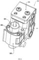
- the cutting tool assembly comprises a sliding seat which is sleeved on and slidable along the slide rod, a cutting tool body disposed in an inner side of the sliding seat, and a pressing assembly disposed at a front end of the cutting tool body.
- a semi-circular receiving groove is formed in a position, corresponding to the cutting tool body, of the inner side of the sliding seat.
- the first pressing member is connected to an inner side of a front end of the sliding seat through a movable pin
- the second pressing member is connected to an inner side of a prominent portion of the first pressing member through another movable pin.
- return torsion springs are disposed at a joint between the movable pin and the sliding seat, as well as a joint between the another movable pin and the first pressing member.
- the upper transmission assembly comprises an upper rotating shaft, an upper cam is fixedly disposed around the upper rotating shaft.
- the lower transmission assembly comprises a driving motor, a driving belt wheel is disposed at an end of an output shaft of the driving motor, a transmission belt wheel is disposed at a position, corresponding to the driving belt wheel, of a side of the cutting plotter shell, a transmission belt is disposed between the transmission belt wheel and the driving belt wheel, a lower rotating shaft is disposed on an inner side of the transmission belt, and a lower cam is fixedly disposed around a position, corresponding to the upper cam, of the lower rotating shaft.
- the upper cam and the lower cam rotate in opposite directions when working.
- the present invention provides a cutting plotter which comprises a cutting plotter shell, a placement plate disposed outside the cutting plotter shell, and an upper transmission assembly and a lower transmission assembly which are disposed in the cutting plotter shell.
- the cutting plotter further comprises a belt assembly disposed in the cutting plotter, and the lower transmission assembly and the upper transmission assembly correspond to each other to assist paper in entering the cutting plotter.
- a slide rod is disposed in the cutting plotter shell and located at a top of the upper transmission assembly, and a cutting tool assembly is disposed around the slide rod.
- the belt assembly comprises a driving motor, a driving wheel is disposed at an end of an output shaft of the driving motor, the driving wheel is meshed with a driven wheel, a driven belt wheel is disposed on a concentric shaft of the driven wheel, a steering belt wheel is disposed in front of the driven belt wheel, tensioning belt wheels are disposed at two ends of the steering belt wheel, a belt body is disposed around the belt wheels, and the cutting tool assembly is disposed on and driven by the belt body.
- the cutting tool assembly comprises a sliding seat which is sleeved on and slidable along the slide rod, a cutting tool body disposed in an inner side of the sliding seat, and a pressing assembly disposed at an end of the cutting tool body; and the pressing assembly comprises a first pressing member and a second pressing member each of which comprises a wrench and a pressing body formed integrally.
- the first pressing member is connected to an inner side of a front end of the sliding seat through a movable pin
- the second pressing member is connected to an inner side of a prominent portion of the first pressing member through another movable pin.
- return torsion springs are disposed at a joint between the movable pin and the sliding seat, as well as a joint between the another movable pin and the first pressing member.
- cutting plotter shell 10
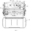
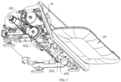
- a cutting plotter in accordance with an embodiment of the preset invention comprises a cutting plotter shell 10, a placement plate 20 disposed outside the cutting plotter shell 10, an upper transmission assembly 50 and a lower transmission assembly 40 disposed at two ends of the cutting plotter shell 10, and a belt assembly 60.
- the lower transmission assembly 40 and the upper transmission assembly 50 correspond to each other to assist paper in entering the cutting plotter.
- a slide rod 70 is disposed in the cutting plotter shell 10 and is located at the top of the upper transmission assembly 50, and a cutting tool assembly 30 is disposed on an outer side of the slide rod 70.
- the belt assembly 60 comprises a driving motor 601, a driving wheel 604 is disposed at an end of an output shaft of the driving motor 601, one side of the driving wheel 604 is meshed with a driven wheel 602, a driven belt wheel 605 is disposed on a concentric shaft of the driven wheel 602, a steering belt wheel 606 is disposed in front of the driven belt wheel 605, tensioning belt wheels 607 are disposed at two ends of the steering belt wheel 606, a belt body 603 is disposed around the belt wheels 605, 606, 607, and the cutting tool assembly 30 is disposed on an outer side of the belt body 603.
- the driving motor 601 drives the belt assembly 60 to work, and the driving wheel 604 rotates along with the driving motor 601 to drive the driven wheel 602 to rotate.
- the driven wheel 602 and the driven belt wheel 605 share the same rotating shaft to cause the driven belt wheel 605 to rotate along with the driven wheel 602.
- the belt body 603 disposed around the driven belt wheel 605, the steering belt wheel 606 and the two tensioning belt wheels 607 drives the cutting tool assembly 30 disposed on the outer side of the belt body 603 to move to thereby plot a graphic or text on the paper or other materials mainly through the cutting tool body 304 of the cutting tool assembly 30, and the paper plotted with the graphic or text is output to be placed on the placement plate 20.
Landscapes
- Engineering & Computer Science (AREA)
- Mechanical Engineering (AREA)
- Life Sciences & Earth Sciences (AREA)
- Forests & Forestry (AREA)
- Devices For Conveying Motion By Means Of Endless Flexible Members (AREA)
Applications Claiming Priority (1)
| Application Number | Priority Date | Filing Date | Title |
|---|---|---|---|
| CN202211578200.6A CN115946173A (zh) | 2022-12-09 | 2022-12-09 | 一种刻印机 |
Publications (2)
| Publication Number | Publication Date |
|---|---|
| EP4397461A1 true EP4397461A1 (de) | 2024-07-10 |
| EP4397461B1 EP4397461B1 (de) | 2026-02-18 |
Family
ID=85885342
Family Applications (1)
| Application Number | Title | Priority Date | Filing Date |
|---|---|---|---|
| EP23178841.5A Active EP4397461B1 (de) | 2022-12-09 | 2023-06-13 | Schneidplotter |
Country Status (4)
| Country | Link |
|---|---|
| US (1) | US11731847B1 (de) |
| EP (1) | EP4397461B1 (de) |
| CN (1) | CN115946173A (de) |
| AU (1) | AU2023278012B2 (de) |
Families Citing this family (9)
| Publication number | Priority date | Publication date | Assignee | Title |
|---|---|---|---|---|
| CA3221501A1 (en) * | 2013-02-20 | 2014-08-28 | Cricut, Inc, | Electronic cutting machine |
| USD986317S1 (en) * | 2020-01-10 | 2023-05-16 | Cricut, Inc. | Cutting machine tool clamp |
| USD987714S1 (en) * | 2020-01-10 | 2023-05-30 | Cricut, Inc. | Cutting machine having a reduced form factor |
| USD1029929S1 (en) * | 2022-04-28 | 2024-06-04 | Siser NA | Cutter |
| USD1017692S1 (en) * | 2022-04-28 | 2024-03-12 | Siser NA | Cutter |
| USD1033531S1 (en) * | 2022-06-27 | 2024-07-02 | Shenzhen Aiduoduo Technology Co., Ltd. | Cutting plotter |
| USD1069861S1 (en) * | 2023-04-21 | 2025-04-08 | Proasia Holdings Limited | Electronic cutting machine |
| USD1039042S1 (en) * | 2024-03-20 | 2024-08-13 | Xi LEI | Engraving machine |
| USD1065322S1 (en) * | 2024-05-23 | 2025-03-04 | Xiwing E-Commerce (Zhuhai) Co., Ltd | Cutting machine |
Citations (1)
| Publication number | Priority date | Publication date | Assignee | Title |
|---|---|---|---|---|
| JP2007136647A (ja) * | 2005-11-22 | 2007-06-07 | Seiko Epson Corp | 読取裁断複合装置および裁断方法 |
Family Cites Families (35)
| Publication number | Priority date | Publication date | Assignee | Title |
|---|---|---|---|---|
| US3600998A (en) * | 1969-12-29 | 1971-08-24 | Gen Electric | A ticket punching mechanism and stop assembly |
| US3958477A (en) * | 1972-05-25 | 1976-05-25 | Carlson Richard L | Flat stock cutter |
| US5816720A (en) * | 1994-03-15 | 1998-10-06 | Interbold | Printer mechanism for automated teller machine |
| US6092450A (en) * | 1997-04-01 | 2000-07-25 | Dueck; Raymond | Rotary cutter for sheet material |
| JP3736824B2 (ja) * | 1997-09-30 | 2006-01-18 | キヤノンファインテック株式会社 | 記録媒体裁断装置 |
| DE19914194C2 (de) * | 1999-03-24 | 2001-09-27 | Mannesmann Ag | Schneidmaschine mit rotierend angetriebenem Schneidmesser |
| JP3832799B2 (ja) * | 1999-12-08 | 2006-10-11 | 富士写真フイルム株式会社 | シート切断装置及びカッタ付きプリンタ |
| JP3837156B2 (ja) * | 2000-08-28 | 2006-10-25 | シチズン時計株式会社 | 用紙切断装置 |
| US20050061127A1 (en) * | 2003-07-14 | 2005-03-24 | Kasper Kazmier J. | Device for dispensing a paper product |
| US7197971B2 (en) * | 2003-07-18 | 2007-04-03 | Hewlett-Packard Development Company, L.P. | Device for trimming sheet material |
| US8156852B2 (en) * | 2004-01-22 | 2012-04-17 | Graphtec Kabushiki Kaisha | Cutting plotter, cutting plotter driving control device, cut target medium supporting sheet, cut target medium, cutting pen, method of manufacturing paper product, and method of generating cut data |
| CN100554112C (zh) * | 2004-01-29 | 2009-10-28 | 美克司株式会社 | 纸张处理装置 |
| US20080078497A1 (en) * | 2004-08-13 | 2008-04-03 | Leyhatton Innovations Limited | Method and Means of Applying Adhesive Tape |
| US7669540B2 (en) * | 2007-04-25 | 2010-03-02 | L&P Property Management Company | Soft goods slitter and feed system for quilting |
| US20100011931A1 (en) * | 2008-07-16 | 2010-01-21 | Wen-Lung Chang | Plastic film cutting device |
| CN201604454U (zh) * | 2009-11-26 | 2010-10-13 | 安徽嘉臣智能数控科技有限公司 | 一种桌面型刻字机 |
| JP5793893B2 (ja) * | 2011-03-04 | 2015-10-14 | 株式会社リコー | シート切断装置およびこれを備えた画像形成装置 |
| US8567775B2 (en) * | 2011-09-30 | 2013-10-29 | Lexmark International, Inc. | Translatable roller media aligning mechanism |
| JP2013193193A (ja) * | 2012-03-22 | 2013-09-30 | Brother Industries Ltd | 切断装置 |
| JP5598494B2 (ja) * | 2012-04-20 | 2014-10-01 | コニカミノルタ株式会社 | 断裁機及び画像形成システム |
| DE102012009532A1 (de) * | 2012-05-04 | 2013-11-07 | Hell Gravure Systems Gmbh & Co. Kg | Gravierorgan zur Gravur von Druckformen |
| US9132566B2 (en) * | 2013-03-14 | 2015-09-15 | Chung Sheen Technology Co., Ltd. | Automated book punch |
| JP2014231103A (ja) * | 2013-05-28 | 2014-12-11 | ブラザー工業株式会社 | 加工装置、及びデータ処理プログラム |
| US9511503B2 (en) * | 2013-12-19 | 2016-12-06 | Seiko Ltd. | Trimmer apparatus |
| JP2015124044A (ja) * | 2013-12-26 | 2015-07-06 | セイコーエプソン株式会社 | ベルト搬送装置、媒体搬送装置ならびにプリンター |
| JP2015150647A (ja) * | 2014-02-14 | 2015-08-24 | ブラザー工業株式会社 | 保持部材及び切断装置 |
| US9463577B2 (en) * | 2014-04-01 | 2016-10-11 | Tim Martin | Paper cutting mechanisms |
| CN106114031A (zh) * | 2016-06-30 | 2016-11-16 | 合肥卡星数控设备有限公司 | 一种加工稳定型刻字机小车 |
| US11446940B2 (en) * | 2018-01-31 | 2022-09-20 | Hewlett-Packard Development Company, L.P. | Cutter assembly with movable trench cover |
| ES2734498B2 (es) * | 2018-05-07 | 2021-12-16 | Goiti S Coop | Maquina para corte de laminas por proyeccion de fluidos |
| AU2020403124B2 (en) * | 2019-12-12 | 2024-06-20 | Cricut, Inc. | Matless cutting machine and methods |
| CN211441777U (zh) * | 2019-12-16 | 2020-09-08 | 卞显兵 | 一种新型刻字机 |
| US20210331888A1 (en) * | 2020-04-28 | 2021-10-28 | Silhouette America, Inc. | Sheet holder |
| JP7441510B2 (ja) * | 2020-08-26 | 2024-03-01 | デュプロ精工株式会社 | シート加工装置 |
| CN218984972U (zh) * | 2022-12-09 | 2023-05-09 | 深圳爱多多智能装备科技有限公司 | 一种刻印机 |
-
2022
- 2022-12-09 CN CN202211578200.6A patent/CN115946173A/zh active Pending
-
2023
- 2023-02-13 US US18/167,904 patent/US11731847B1/en active Active
- 2023-06-13 EP EP23178841.5A patent/EP4397461B1/de active Active
- 2023-12-05 AU AU2023278012A patent/AU2023278012B2/en active Active
Patent Citations (1)
| Publication number | Priority date | Publication date | Assignee | Title |
|---|---|---|---|---|
| JP2007136647A (ja) * | 2005-11-22 | 2007-06-07 | Seiko Epson Corp | 読取裁断複合装置および裁断方法 |
Also Published As
| Publication number | Publication date |
|---|---|
| AU2023278012A1 (en) | 2024-06-27 |
| AU2023278012B2 (en) | 2024-10-17 |
| CN115946173A (zh) | 2023-04-11 |
| US11731847B1 (en) | 2023-08-22 |
| EP4397461B1 (de) | 2026-02-18 |
Similar Documents
| Publication | Publication Date | Title |
|---|---|---|
| AU2023278012B2 (en) | Cutting plotter | |
| CN218984972U (zh) | 一种刻印机 | |
| CN114260342A (zh) | 一种金属板材连续折弯设备 | |
| CN107146513A (zh) | 教学演示教具 | |
| CN201026911Y (zh) | 电控气动转向装置 | |
| CN201168878Y (zh) | 机床工作台多功能运动机构 | |
| CN206287242U (zh) | 一种具有微调的平压压痕切线机 | |
| CN214643857U (zh) | 一种便于调节的切纸机 | |
| JP4444546B2 (ja) | 摩擦攪拌接合装置 | |
| CN211966022U (zh) | 一种定位精准的钻孔机 | |
| CN209793046U (zh) | 一种端子压入机治具 | |
| CN203636878U (zh) | 一种圆角机刀具传动装置 | |
| JP4771454B2 (ja) | 板金加工装置及びその方法 | |
| CN224043152U (zh) | 一种主齿法兰钻孔装置 | |
| CN220374151U (zh) | 胶装机及其内页夹紧机构 | |
| CN223507968U (zh) | 打印机 | |
| CN211842113U (zh) | 一种便于对纸板进行固定的平压压痕切线机 | |
| CN214355070U (zh) | 一种用于胶装机的压紧装置 | |
| US4579056A (en) | Printing mechanism | |
| CN211842114U (zh) | 一种平压压痕切线机 | |
| CN219725183U (zh) | 一种用于机车电机轴承的推进装置 | |
| JP2601119Y2 (ja) | パイプカッタ | |
| CN219726082U (zh) | 一种快速便携式履带换销机 | |
| CN219381930U (zh) | 一种用于装帧布的印刷机构 | |
| CN201685473U (zh) | 压力机模高手动调节装置 |
Legal Events
| Date | Code | Title | Description |
|---|---|---|---|
| PUAI | Public reference made under article 153(3) epc to a published international application that has entered the european phase |
Free format text: ORIGINAL CODE: 0009012 |
|
| STAA | Information on the status of an ep patent application or granted ep patent |
Free format text: STATUS: REQUEST FOR EXAMINATION WAS MADE |
|
| 17P | Request for examination filed |
Effective date: 20230711 |
|
| AK | Designated contracting states |
Kind code of ref document: A1 Designated state(s): AL AT BE BG CH CY CZ DE DK EE ES FI FR GB GR HR HU IE IS IT LI LT LU LV MC ME MK MT NL NO PL PT RO RS SE SI SK SM TR |
|
| GRAP | Despatch of communication of intention to grant a patent |
Free format text: ORIGINAL CODE: EPIDOSNIGR1 |
|
| STAA | Information on the status of an ep patent application or granted ep patent |
Free format text: STATUS: GRANT OF PATENT IS INTENDED |
|
| INTG | Intention to grant announced |
Effective date: 20250911 |
|
| GRAS | Grant fee paid |
Free format text: ORIGINAL CODE: EPIDOSNIGR3 |
|
| GRAA | (expected) grant |
Free format text: ORIGINAL CODE: 0009210 |
|
| STAA | Information on the status of an ep patent application or granted ep patent |
Free format text: STATUS: THE PATENT HAS BEEN GRANTED |
|
| AK | Designated contracting states |
Kind code of ref document: B1 Designated state(s): AL AT BE BG CH CY CZ DE DK EE ES FI FR GB GR HR HU IE IS IT LI LT LU LV MC ME MK MT NL NO PL PT RO RS SE SI SK SM TR |
|
| REG | Reference to a national code |
Ref country code: CH Ref legal event code: F10 Free format text: ST27 STATUS EVENT CODE: U-0-0-F10-F00 (AS PROVIDED BY THE NATIONAL OFFICE) Effective date: 20260218 Ref country code: GB Ref legal event code: FG4D |
|
| REG | Reference to a national code |
Ref country code: IE Ref legal event code: FG4D |
|
| REG | Reference to a national code |
Ref country code: DE Ref legal event code: R096 Ref document number: 602023012079 Country of ref document: DE |