EP4397441A2 - Pneumatisches werkzeug - Google Patents
Pneumatisches werkzeug Download PDFInfo
- Publication number
- EP4397441A2 EP4397441A2 EP24177909.9A EP24177909A EP4397441A2 EP 4397441 A2 EP4397441 A2 EP 4397441A2 EP 24177909 A EP24177909 A EP 24177909A EP 4397441 A2 EP4397441 A2 EP 4397441A2
- Authority
- EP
- European Patent Office
- Prior art keywords
- timer
- trigger
- piston
- timer switch
- valve
- Prior art date
- Legal status (The legal status is an assumption and is not a legal conclusion. Google has not performed a legal analysis and makes no representation as to the accuracy of the status listed.)
- Pending
Links
- 238000005259 measurement Methods 0.000 description 6
- 230000002093 peripheral effect Effects 0.000 description 6
- 238000004891 communication Methods 0.000 description 2
- 230000006835 compression Effects 0.000 description 2
- 238000007906 compression Methods 0.000 description 2
- 238000010304 firing Methods 0.000 description 1
- 238000003780 insertion Methods 0.000 description 1
- 230000037431 insertion Effects 0.000 description 1
- 239000010687 lubricating oil Substances 0.000 description 1
- 238000000034 method Methods 0.000 description 1
- 238000012986 modification Methods 0.000 description 1
- 230000004048 modification Effects 0.000 description 1
- 238000011144 upstream manufacturing Methods 0.000 description 1
Images


Classifications
-
- B—PERFORMING OPERATIONS; TRANSPORTING
- B25—HAND TOOLS; PORTABLE POWER-DRIVEN TOOLS; MANIPULATORS
- B25C—HAND-HELD NAILING OR STAPLING TOOLS; MANUALLY OPERATED PORTABLE STAPLING TOOLS
- B25C1/00—Hand-held nailing tools; Nail feeding devices
- B25C1/04—Hand-held nailing tools; Nail feeding devices operated by fluid pressure, e.g. by air pressure
- B25C1/047—Mechanical details
-
- B—PERFORMING OPERATIONS; TRANSPORTING
- B25—HAND TOOLS; PORTABLE POWER-DRIVEN TOOLS; MANIPULATORS
- B25C—HAND-HELD NAILING OR STAPLING TOOLS; MANUALLY OPERATED PORTABLE STAPLING TOOLS
- B25C1/00—Hand-held nailing tools; Nail feeding devices
- B25C1/008—Safety devices
-
- H—ELECTRICITY
- H01—ELECTRIC ELEMENTS
- H01H—ELECTRIC SWITCHES; RELAYS; SELECTORS; EMERGENCY PROTECTIVE DEVICES
- H01H43/00—Time or time-programme switches providing a choice of time-intervals for executing one or more switching actions and automatically terminating their operations after the programme is completed
-
- B—PERFORMING OPERATIONS; TRANSPORTING
- B25—HAND TOOLS; PORTABLE POWER-DRIVEN TOOLS; MANIPULATORS
- B25C—HAND-HELD NAILING OR STAPLING TOOLS; MANUALLY OPERATED PORTABLE STAPLING TOOLS
- B25C1/00—Hand-held nailing tools; Nail feeding devices
- B25C1/04—Hand-held nailing tools; Nail feeding devices operated by fluid pressure, e.g. by air pressure
- B25C1/041—Hand-held nailing tools; Nail feeding devices operated by fluid pressure, e.g. by air pressure with fixed main cylinder
- B25C1/043—Trigger valve and trigger mechanism
Definitions
- the present disclosure relates to a pneumatic tool.
- a pneumatic tool may operate to erroneously fire a nail when the contact arm is inadvertently pushed while the trigger is stilled pulled. Therefore, in a pneumatic tool, in order to prevent unintentional erroneous firing of a nail, a timer is provided to limit the operation of the pneumatic tool when a certain period of time has elapsed in a state where a trigger is pulled.
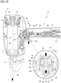
- FIG. 1 is a side sectional view of a nailing machine 1 according to the present embodiment
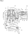
- FIG. 2 is an enlarged view of a trigger valve 30, a trigger 50, a timer switch 60, and a link member 70 according to the present embodiment
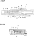
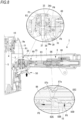
- FIG. 3A is an enlarged view of a timer 8 according to the present embodiment
- FIG. 3B is an enlarged view of a throttle part 90 constituting the timer according to the present embodiment.
- FIGS. 1 and 2 show a state before compressed air is supplied into a main chamber 15 of the nailing machine 1
- FIGS. 3A and 3B show a state while compressed air is supplied into the main chamber 15 of the nailing machine 1.
- the side where the contact arm 20 is provided is defined as the lower side of the nailing machine 1, and the opposite side thereof is defined as the upper side of the nailing machine 1. Further, the side where a housing 2 is provided is defined as the front side of the nailing machine 1, and the opposite side thereof is defined as the rear side of the nailing machine 1.
- a striking cylinder 3 is provided inside the housing 2, and a striking piston 4 is provided inside the striking cylinder 3 so as to be slidable in an upper and lower direction (axial direction).
- a rod-shaped striking driver 5 is integrally connected to a lower surface of the striking piston 4. The striking piston 4 is driven by compressed air supplied from the main chamber 15 and guides the striking driver 5 to the nose 6 to strike out a nail (not shown) supplied from the magazine 22 to the hose 6 toward an object.
- the contact arm 20 is provided on the tip side of the nose 6 and is connected to a rod 20a.
- the contact arm 20 is configured to be reciprocally movable along an axial direction of the nose 6.
- the contact arm 20 is urged by a compression spring 20b so as to protrude downward from a tip portion of the nose 6 and relatively moves in the direction of compressing the compression spring 20b against the nose 6 by its tip portion being pressed against an object.
- An upper end portion of the rod 20a is in contact with the contact lever 54 and presses the contact lever 54 upward in conjunction with a pressing operation of the contact arm 20.
- the timer switch 60 and the timer 8 can be operated via the link member 70 by pulling the trigger 50.
- the operation load of the trigger 50 can be reduced, and as a result, the operation load of the operator can be reduced.
- the operation load of the trigger 50 can be set depending on the setting (lever ratio) of the first length L1 between the shaft 72 of the link member 70 and the one end portion 70a and the second length L2 between the shaft 72 and the other end portion 70b.
Landscapes
- Engineering & Computer Science (AREA)
- Mechanical Engineering (AREA)
- Physics & Mathematics (AREA)
- Fluid Mechanics (AREA)
- Portable Nailing Machines And Staplers (AREA)
Applications Claiming Priority (2)
| Application Number | Priority Date | Filing Date | Title |
|---|---|---|---|
| JP2020113616A JP7463883B2 (ja) | 2020-06-30 | 2020-06-30 | 空気圧工具 |
| EP21182501.3A EP3932618B1 (de) | 2020-06-30 | 2021-06-29 | Pneumatisches werkzeug |
Related Parent Applications (1)
| Application Number | Title | Priority Date | Filing Date |
|---|---|---|---|
| EP21182501.3A Division EP3932618B1 (de) | 2020-06-30 | 2021-06-29 | Pneumatisches werkzeug |
Publications (2)
| Publication Number | Publication Date |
|---|---|
| EP4397441A2 true EP4397441A2 (de) | 2024-07-10 |
| EP4397441A3 EP4397441A3 (de) | 2024-11-06 |
Family
ID=76708104
Family Applications (2)
| Application Number | Title | Priority Date | Filing Date |
|---|---|---|---|
| EP21182501.3A Active EP3932618B1 (de) | 2020-06-30 | 2021-06-29 | Pneumatisches werkzeug |
| EP24177909.9A Pending EP4397441A3 (de) | 2020-06-30 | 2021-06-29 | Pneumatisches werkzeug |
Family Applications Before (1)
| Application Number | Title | Priority Date | Filing Date |
|---|---|---|---|
| EP21182501.3A Active EP3932618B1 (de) | 2020-06-30 | 2021-06-29 | Pneumatisches werkzeug |
Country Status (4)
| Country | Link |
|---|---|
| US (1) | US12090613B2 (de) |
| EP (2) | EP3932618B1 (de) |
| JP (1) | JP7463883B2 (de) |
| TW (1) | TWI867228B (de) |
Families Citing this family (1)
| Publication number | Priority date | Publication date | Assignee | Title |
|---|---|---|---|---|
| US12539592B2 (en) * | 2023-09-14 | 2026-02-03 | Milwaukee Electric Tool Corporation | Power tool brake abort |
Family Cites Families (9)
| Publication number | Priority date | Publication date | Assignee | Title |
|---|---|---|---|---|
| JP3287172B2 (ja) * | 1995-04-05 | 2002-05-27 | マックス株式会社 | 釘打ち機のトリガ装置 |
| US6604664B2 (en) | 2001-01-16 | 2003-08-12 | Illinois Tool Works Inc. | Safe trigger with time delay for pneumatic fastener driving tools |
| JP6408944B2 (ja) * | 2015-03-24 | 2018-10-17 | 株式会社マキタ | 打ち込み工具 |
| FR3045784B1 (fr) * | 2015-12-18 | 2019-03-22 | Illinois Tool Works Inc | Procede de controle d'actionnement d'un outil de fixation a gaz et dispositif correspondant |
| JP6824781B2 (ja) | 2017-03-01 | 2021-02-03 | 株式会社マキタ | 打ち込み工具 |
| JP6833565B2 (ja) | 2017-03-01 | 2021-02-24 | 株式会社マキタ | 打ち込み工具 |
| JP6950424B2 (ja) | 2017-09-29 | 2021-10-13 | マックス株式会社 | 打込み工具 |
| US11065749B2 (en) * | 2018-03-26 | 2021-07-20 | Tti (Macao Commercial Offshore) Limited | Powered fastener driver |
| CN111936272A (zh) | 2018-03-29 | 2020-11-13 | 工机控股株式会社 | 打入机 |
-
2020
- 2020-06-30 JP JP2020113616A patent/JP7463883B2/ja active Active
-
2021
- 2021-06-29 TW TW110123775A patent/TWI867228B/zh active
- 2021-06-29 EP EP21182501.3A patent/EP3932618B1/de active Active
- 2021-06-29 US US17/361,731 patent/US12090613B2/en active Active
- 2021-06-29 EP EP24177909.9A patent/EP4397441A3/de active Pending
Also Published As
| Publication number | Publication date |
|---|---|
| EP3932618B1 (de) | 2024-06-26 |
| US20210402578A1 (en) | 2021-12-30 |
| EP3932618C0 (de) | 2024-06-26 |
| EP4397441A3 (de) | 2024-11-06 |
| JP7463883B2 (ja) | 2024-04-09 |
| TWI867228B (zh) | 2024-12-21 |
| TW202216378A (zh) | 2022-05-01 |
| JP2022012074A (ja) | 2022-01-17 |
| US12090613B2 (en) | 2024-09-17 |
| EP3932618A1 (de) | 2022-01-05 |
Similar Documents
| Publication | Publication Date | Title |
|---|---|---|
| EP3461590B1 (de) | Schraubwerkzeug | |
| JP7043771B2 (ja) | 打込み工具 | |
| AU2018351907B2 (en) | Compressed air nailer with a safety actuator | |
| EP3932618B1 (de) | Pneumatisches werkzeug | |
| US7422134B2 (en) | Variable outward clinch stapler | |
| TWI871477B (zh) | 氣動工具 | |
| EP3461591B1 (de) | Schraubwerkzeug | |
| JP7108369B2 (ja) | 単発および接触トリガを有する空気釘打機 | |
| AU2018361393A1 (en) | Pneumatic nail gun having a safety valve assembly | |
| US20230278178A1 (en) | Pneumatic tool | |
| US11780067B2 (en) | Pneumatic tool | |
| JP2023014364A (ja) | 空気圧工具 | |
| JP7205372B2 (ja) | 空気圧工具 | |
| JPH09272026A (ja) | 制御弁装置および起動感度調節装置付のファスナ駆動装置 | |
| JP2022001393A (ja) | 打込機 |
Legal Events
| Date | Code | Title | Description |
|---|---|---|---|
| PUAI | Public reference made under article 153(3) epc to a published international application that has entered the european phase |
Free format text: ORIGINAL CODE: 0009012 |
|
| STAA | Information on the status of an ep patent application or granted ep patent |
Free format text: STATUS: REQUEST FOR EXAMINATION WAS MADE |
|
| 17P | Request for examination filed |
Effective date: 20240524 |
|
| AC | Divisional application: reference to earlier application |
Ref document number: 3932618 Country of ref document: EP Kind code of ref document: P |
|
| AK | Designated contracting states |
Kind code of ref document: A2 Designated state(s): AL AT BE BG CH CY CZ DE DK EE ES FI FR GB GR HR HU IE IS IT LI LT LU LV MC MK MT NL NO PL PT RO RS SE SI SK SM TR |
|
| REG | Reference to a national code |
Ref country code: DE Ref legal event code: R079 Free format text: PREVIOUS MAIN CLASS: B25C0001000000 Ipc: B25C0001040000 |
|
| PUAL | Search report despatched |
Free format text: ORIGINAL CODE: 0009013 |
|
| AK | Designated contracting states |
Kind code of ref document: A3 Designated state(s): AL AT BE BG CH CY CZ DE DK EE ES FI FR GB GR HR HU IE IS IT LI LT LU LV MC MK MT NL NO PL PT RO RS SE SI SK SM TR |
|
| RIC1 | Information provided on ipc code assigned before grant |
Ipc: B25C 1/00 20060101ALI20241002BHEP Ipc: B25C 1/04 20060101AFI20241002BHEP |