EP4397279A2 - Herzklappenandockvorrichtungen und -systeme - Google Patents
Herzklappenandockvorrichtungen und -systeme Download PDFInfo
- Publication number
- EP4397279A2 EP4397279A2 EP24177295.3A EP24177295A EP4397279A2 EP 4397279 A2 EP4397279 A2 EP 4397279A2 EP 24177295 A EP24177295 A EP 24177295A EP 4397279 A2 EP4397279 A2 EP 4397279A2
- Authority
- EP
- European Patent Office
- Prior art keywords
- docking device
- coil
- valve
- docking
- turn
- Prior art date
- Legal status (The legal status is an assumption and is not a legal conclusion. Google has not performed a legal analysis and makes no representation as to the accuracy of the status listed.)
- Pending
Links
Images
















Classifications
-
- A—HUMAN NECESSITIES
- A61—MEDICAL OR VETERINARY SCIENCE; HYGIENE
- A61F—FILTERS IMPLANTABLE INTO BLOOD VESSELS; PROSTHESES; DEVICES PROVIDING PATENCY TO, OR PREVENTING COLLAPSING OF, TUBULAR STRUCTURES OF THE BODY, e.g. STENTS; ORTHOPAEDIC, NURSING OR CONTRACEPTIVE DEVICES; FOMENTATION; TREATMENT OR PROTECTION OF EYES OR EARS; BANDAGES, DRESSINGS OR ABSORBENT PADS; FIRST-AID KITS
- A61F2/00—Filters implantable into blood vessels; Prostheses, i.e. artificial substitutes or replacements for parts of the body; Appliances for connecting them with the body; Devices providing patency to, or preventing collapsing of, tubular structures of the body, e.g. stents
- A61F2/02—Prostheses implantable into the body
- A61F2/24—Heart valves ; Vascular valves, e.g. venous valves; Heart implants, e.g. passive devices for improving the function of the native valve or the heart muscle; Transmyocardial revascularisation [TMR] devices; Valves implantable in the body
- A61F2/2442—Annuloplasty rings or inserts for correcting the valve shape; Implants for improving the function of a native heart valve
- A61F2/2463—Implants forming part of the valve leaflets
-
- A—HUMAN NECESSITIES
- A61—MEDICAL OR VETERINARY SCIENCE; HYGIENE
- A61F—FILTERS IMPLANTABLE INTO BLOOD VESSELS; PROSTHESES; DEVICES PROVIDING PATENCY TO, OR PREVENTING COLLAPSING OF, TUBULAR STRUCTURES OF THE BODY, e.g. STENTS; ORTHOPAEDIC, NURSING OR CONTRACEPTIVE DEVICES; FOMENTATION; TREATMENT OR PROTECTION OF EYES OR EARS; BANDAGES, DRESSINGS OR ABSORBENT PADS; FIRST-AID KITS
- A61F2/00—Filters implantable into blood vessels; Prostheses, i.e. artificial substitutes or replacements for parts of the body; Appliances for connecting them with the body; Devices providing patency to, or preventing collapsing of, tubular structures of the body, e.g. stents
- A61F2/02—Prostheses implantable into the body
- A61F2/24—Heart valves ; Vascular valves, e.g. venous valves; Heart implants, e.g. passive devices for improving the function of the native valve or the heart muscle; Transmyocardial revascularisation [TMR] devices; Valves implantable in the body
- A61F2/2409—Support rings therefor, e.g. for connecting valves to tissue
-
- A—HUMAN NECESSITIES
- A61—MEDICAL OR VETERINARY SCIENCE; HYGIENE
- A61F—FILTERS IMPLANTABLE INTO BLOOD VESSELS; PROSTHESES; DEVICES PROVIDING PATENCY TO, OR PREVENTING COLLAPSING OF, TUBULAR STRUCTURES OF THE BODY, e.g. STENTS; ORTHOPAEDIC, NURSING OR CONTRACEPTIVE DEVICES; FOMENTATION; TREATMENT OR PROTECTION OF EYES OR EARS; BANDAGES, DRESSINGS OR ABSORBENT PADS; FIRST-AID KITS
- A61F2/00—Filters implantable into blood vessels; Prostheses, i.e. artificial substitutes or replacements for parts of the body; Appliances for connecting them with the body; Devices providing patency to, or preventing collapsing of, tubular structures of the body, e.g. stents
- A61F2/02—Prostheses implantable into the body
- A61F2/24—Heart valves ; Vascular valves, e.g. venous valves; Heart implants, e.g. passive devices for improving the function of the native valve or the heart muscle; Transmyocardial revascularisation [TMR] devices; Valves implantable in the body
- A61F2/2412—Heart valves ; Vascular valves, e.g. venous valves; Heart implants, e.g. passive devices for improving the function of the native valve or the heart muscle; Transmyocardial revascularisation [TMR] devices; Valves implantable in the body with soft flexible valve members, e.g. tissue valves shaped like natural valves
-
- A—HUMAN NECESSITIES
- A61—MEDICAL OR VETERINARY SCIENCE; HYGIENE
- A61F—FILTERS IMPLANTABLE INTO BLOOD VESSELS; PROSTHESES; DEVICES PROVIDING PATENCY TO, OR PREVENTING COLLAPSING OF, TUBULAR STRUCTURES OF THE BODY, e.g. STENTS; ORTHOPAEDIC, NURSING OR CONTRACEPTIVE DEVICES; FOMENTATION; TREATMENT OR PROTECTION OF EYES OR EARS; BANDAGES, DRESSINGS OR ABSORBENT PADS; FIRST-AID KITS
- A61F2/00—Filters implantable into blood vessels; Prostheses, i.e. artificial substitutes or replacements for parts of the body; Appliances for connecting them with the body; Devices providing patency to, or preventing collapsing of, tubular structures of the body, e.g. stents
- A61F2/02—Prostheses implantable into the body
- A61F2/24—Heart valves ; Vascular valves, e.g. venous valves; Heart implants, e.g. passive devices for improving the function of the native valve or the heart muscle; Transmyocardial revascularisation [TMR] devices; Valves implantable in the body
- A61F2/2412—Heart valves ; Vascular valves, e.g. venous valves; Heart implants, e.g. passive devices for improving the function of the native valve or the heart muscle; Transmyocardial revascularisation [TMR] devices; Valves implantable in the body with soft flexible valve members, e.g. tissue valves shaped like natural valves
- A61F2/2418—Scaffolds therefor, e.g. support stents
-
- A—HUMAN NECESSITIES
- A61—MEDICAL OR VETERINARY SCIENCE; HYGIENE
- A61F—FILTERS IMPLANTABLE INTO BLOOD VESSELS; PROSTHESES; DEVICES PROVIDING PATENCY TO, OR PREVENTING COLLAPSING OF, TUBULAR STRUCTURES OF THE BODY, e.g. STENTS; ORTHOPAEDIC, NURSING OR CONTRACEPTIVE DEVICES; FOMENTATION; TREATMENT OR PROTECTION OF EYES OR EARS; BANDAGES, DRESSINGS OR ABSORBENT PADS; FIRST-AID KITS
- A61F2/00—Filters implantable into blood vessels; Prostheses, i.e. artificial substitutes or replacements for parts of the body; Appliances for connecting them with the body; Devices providing patency to, or preventing collapsing of, tubular structures of the body, e.g. stents
- A61F2/02—Prostheses implantable into the body
- A61F2/24—Heart valves ; Vascular valves, e.g. venous valves; Heart implants, e.g. passive devices for improving the function of the native valve or the heart muscle; Transmyocardial revascularisation [TMR] devices; Valves implantable in the body
- A61F2/2427—Devices for manipulating or deploying heart valves during implantation
-
- A—HUMAN NECESSITIES
- A61—MEDICAL OR VETERINARY SCIENCE; HYGIENE
- A61F—FILTERS IMPLANTABLE INTO BLOOD VESSELS; PROSTHESES; DEVICES PROVIDING PATENCY TO, OR PREVENTING COLLAPSING OF, TUBULAR STRUCTURES OF THE BODY, e.g. STENTS; ORTHOPAEDIC, NURSING OR CONTRACEPTIVE DEVICES; FOMENTATION; TREATMENT OR PROTECTION OF EYES OR EARS; BANDAGES, DRESSINGS OR ABSORBENT PADS; FIRST-AID KITS
- A61F2/00—Filters implantable into blood vessels; Prostheses, i.e. artificial substitutes or replacements for parts of the body; Appliances for connecting them with the body; Devices providing patency to, or preventing collapsing of, tubular structures of the body, e.g. stents
- A61F2/02—Prostheses implantable into the body
- A61F2/24—Heart valves ; Vascular valves, e.g. venous valves; Heart implants, e.g. passive devices for improving the function of the native valve or the heart muscle; Transmyocardial revascularisation [TMR] devices; Valves implantable in the body
- A61F2/2427—Devices for manipulating or deploying heart valves during implantation
- A61F2/243—Deployment by mechanical expansion
-
- A—HUMAN NECESSITIES
- A61—MEDICAL OR VETERINARY SCIENCE; HYGIENE
- A61F—FILTERS IMPLANTABLE INTO BLOOD VESSELS; PROSTHESES; DEVICES PROVIDING PATENCY TO, OR PREVENTING COLLAPSING OF, TUBULAR STRUCTURES OF THE BODY, e.g. STENTS; ORTHOPAEDIC, NURSING OR CONTRACEPTIVE DEVICES; FOMENTATION; TREATMENT OR PROTECTION OF EYES OR EARS; BANDAGES, DRESSINGS OR ABSORBENT PADS; FIRST-AID KITS
- A61F2/00—Filters implantable into blood vessels; Prostheses, i.e. artificial substitutes or replacements for parts of the body; Appliances for connecting them with the body; Devices providing patency to, or preventing collapsing of, tubular structures of the body, e.g. stents
- A61F2/02—Prostheses implantable into the body
- A61F2/24—Heart valves ; Vascular valves, e.g. venous valves; Heart implants, e.g. passive devices for improving the function of the native valve or the heart muscle; Transmyocardial revascularisation [TMR] devices; Valves implantable in the body
- A61F2/2427—Devices for manipulating or deploying heart valves during implantation
- A61F2/2436—Deployment by retracting a sheath
-
- A—HUMAN NECESSITIES
- A61—MEDICAL OR VETERINARY SCIENCE; HYGIENE
- A61F—FILTERS IMPLANTABLE INTO BLOOD VESSELS; PROSTHESES; DEVICES PROVIDING PATENCY TO, OR PREVENTING COLLAPSING OF, TUBULAR STRUCTURES OF THE BODY, e.g. STENTS; ORTHOPAEDIC, NURSING OR CONTRACEPTIVE DEVICES; FOMENTATION; TREATMENT OR PROTECTION OF EYES OR EARS; BANDAGES, DRESSINGS OR ABSORBENT PADS; FIRST-AID KITS
- A61F2/00—Filters implantable into blood vessels; Prostheses, i.e. artificial substitutes or replacements for parts of the body; Appliances for connecting them with the body; Devices providing patency to, or preventing collapsing of, tubular structures of the body, e.g. stents
- A61F2/02—Prostheses implantable into the body
- A61F2/24—Heart valves ; Vascular valves, e.g. venous valves; Heart implants, e.g. passive devices for improving the function of the native valve or the heart muscle; Transmyocardial revascularisation [TMR] devices; Valves implantable in the body
- A61F2/2442—Annuloplasty rings or inserts for correcting the valve shape; Implants for improving the function of a native heart valve
- A61F2/2466—Delivery devices therefor
-
- A—HUMAN NECESSITIES
- A61—MEDICAL OR VETERINARY SCIENCE; HYGIENE
- A61B—DIAGNOSIS; SURGERY; IDENTIFICATION
- A61B17/00—Surgical instruments, devices or methods
- A61B17/00234—Surgical instruments, devices or methods for minimally invasive surgery
- A61B2017/00238—Type of minimally invasive operation
- A61B2017/00243—Type of minimally invasive operation cardiac
-
- A—HUMAN NECESSITIES
- A61—MEDICAL OR VETERINARY SCIENCE; HYGIENE
- A61F—FILTERS IMPLANTABLE INTO BLOOD VESSELS; PROSTHESES; DEVICES PROVIDING PATENCY TO, OR PREVENTING COLLAPSING OF, TUBULAR STRUCTURES OF THE BODY, e.g. STENTS; ORTHOPAEDIC, NURSING OR CONTRACEPTIVE DEVICES; FOMENTATION; TREATMENT OR PROTECTION OF EYES OR EARS; BANDAGES, DRESSINGS OR ABSORBENT PADS; FIRST-AID KITS
- A61F2/00—Filters implantable into blood vessels; Prostheses, i.e. artificial substitutes or replacements for parts of the body; Appliances for connecting them with the body; Devices providing patency to, or preventing collapsing of, tubular structures of the body, e.g. stents
- A61F2/95—Instruments specially adapted for placement or removal of stents or stent-grafts
- A61F2002/9528—Instruments specially adapted for placement or removal of stents or stent-grafts for retrieval of stents
-
- A—HUMAN NECESSITIES
- A61—MEDICAL OR VETERINARY SCIENCE; HYGIENE
- A61F—FILTERS IMPLANTABLE INTO BLOOD VESSELS; PROSTHESES; DEVICES PROVIDING PATENCY TO, OR PREVENTING COLLAPSING OF, TUBULAR STRUCTURES OF THE BODY, e.g. STENTS; ORTHOPAEDIC, NURSING OR CONTRACEPTIVE DEVICES; FOMENTATION; TREATMENT OR PROTECTION OF EYES OR EARS; BANDAGES, DRESSINGS OR ABSORBENT PADS; FIRST-AID KITS
- A61F2230/00—Geometry of prostheses classified in groups A61F2/00 - A61F2/26 or A61F2/82 or A61F9/00 or A61F11/00 or subgroups thereof
- A61F2230/0063—Three-dimensional shapes
- A61F2230/0091—Three-dimensional shapes helically-coiled or spirally-coiled, i.e. having a 2-D spiral cross-section
-
- A—HUMAN NECESSITIES
- A61—MEDICAL OR VETERINARY SCIENCE; HYGIENE
- A61F—FILTERS IMPLANTABLE INTO BLOOD VESSELS; PROSTHESES; DEVICES PROVIDING PATENCY TO, OR PREVENTING COLLAPSING OF, TUBULAR STRUCTURES OF THE BODY, e.g. STENTS; ORTHOPAEDIC, NURSING OR CONTRACEPTIVE DEVICES; FOMENTATION; TREATMENT OR PROTECTION OF EYES OR EARS; BANDAGES, DRESSINGS OR ABSORBENT PADS; FIRST-AID KITS
- A61F2250/00—Special features of prostheses classified in groups A61F2/00 - A61F2/26 or A61F2/82 or A61F9/00 or A61F11/00 or subgroups thereof
- A61F2250/0058—Additional features; Implant or prostheses properties not otherwise provided for
- A61F2250/006—Additional features; Implant or prostheses properties not otherwise provided for modular
-
- A—HUMAN NECESSITIES
- A61—MEDICAL OR VETERINARY SCIENCE; HYGIENE
- A61F—FILTERS IMPLANTABLE INTO BLOOD VESSELS; PROSTHESES; DEVICES PROVIDING PATENCY TO, OR PREVENTING COLLAPSING OF, TUBULAR STRUCTURES OF THE BODY, e.g. STENTS; ORTHOPAEDIC, NURSING OR CONTRACEPTIVE DEVICES; FOMENTATION; TREATMENT OR PROTECTION OF EYES OR EARS; BANDAGES, DRESSINGS OR ABSORBENT PADS; FIRST-AID KITS
- A61F2250/00—Special features of prostheses classified in groups A61F2/00 - A61F2/26 or A61F2/82 or A61F9/00 or A61F11/00 or subgroups thereof
- A61F2250/0058—Additional features; Implant or prostheses properties not otherwise provided for
- A61F2250/006—Additional features; Implant or prostheses properties not otherwise provided for modular
- A61F2250/0063—Nested prosthetic parts
Definitions
- the invention generally relates to medical devices and procedures pertaining to prosthetic heart valves. More specifically, the invention relates to replacement of heart valves that may have malformations and/or dysfunctions.
- Embodiments of the invention relate to an anchor or docking device that can hold and maintain a positioning of a prosthetic heart valve for replacing the function of a native heart valve, for example, for a mitral or tricuspid valve replacement procedure, as well as deployment procedures associated with the implantation of such an anchor or docking device and/or of an assembly including the anchor or docking device and a prosthetic heart valve.
- One way to apply existing circular or cylindrical transcatheter valve technology to non-circular valve replacement would be to use an anchor (e.g., a mitral anchor) or docking device or docking station that forms or otherwise provides a more circular docking site at the native valve position (e.g., mitral valve position) to hold such prosthetic valves.
- an anchor e.g., a mitral anchor
- docking device or docking station that forms or otherwise provides a more circular docking site at the native valve position (e.g., mitral valve position) to hold such prosthetic valves.
- existing expandable transcatheter valves developed for the aortic position, or similar valves that have been slightly modified to more effectively replicate mitral valve function could be more securely implanted in such docking devices positioned at the native valve annulus (e.g., native mitral annulus).
- the various docking devices for docking a prosthetic valve at a native valve of a heart can also have a coiled anchor (e.g., which can be the same as or similar to other coiled anchors described in this disclosure) that has a proximal tip and a distal tip and at least one central turn (e.g., a full or partial central turn, which can be the same as or similar to other central turns/coils or functional turns/coils described in this disclosure) that defines a diameter.
- the coiled anchor can also have an upper turn that is connected to the at least one central turn.
- a cover layer can surround the coiled anchor along all or at least a part of the at least one central turn. The cover layer can be connected to the coiled anchor.
- the at least one friction enhancing element can be or include a plurality of lock and key cutouts in an outer surface of the coiled anchor.
- the lock cutouts can be grooves formed in the outer surface of the coiled anchor, and the key cutouts can be protrusions extending outward from the coiled anchor, which can be sized and shaped to fit into the lock cutouts.
- Systems for implanting a docking device at a native valve of a heart can include a docking device (e.g., any docking device described above or elsewhere in this disclosure).
- the docking device can include an opening or bore, and the system can include a suture threaded through the opening or bore.
- the system can also include a delivery catheter, and a pusher device disposed in the delivery catheter.
- the pusher device can include a central lumen that accepts the suture or through which the suture passes.
- the pusher device and suture can be arranged such that pulling the suture pulls the coiled anchor against the pusher device, and retracting the pusher device into the delivery catheter retracts the coiled anchor into the delivery catheter.
- the suture can be disposed in the central lumen such that pulling the suture and/or the pusher device proximally relative to the delivery catheter retracts the coiled anchor or delivery device into the delivery catheter.
- Methods used to implant a docking device for a prosthetic valve at a native heart valve can include a variety of steps (e.g., any of the steps described throughout this disclosure).
- the docking device implanted with these methods can be any of the docking devices described herein.
- a docking device implantable with these steps can have a coiled anchor having at least one full or partial turn defining a central diameter, an extension having a length extending from an upper end of the at least one central turn, and an upper turn extending from an upper end of the extension.
- a delivery catheter can be positioned into a first chamber (e.g., a left atrium) of a heart.
- the extension of the docking device can be advanced such that its upper end is positioned in the first chamber (e.g., the left atrium).
- the upper portion of the docking device can be advanced into the first chamber (e.g., the left atrium) and released, such that the upper portion is in contact with the first chamber wall (e.g., the left atrium wall).
- a replacement prosthetic valve can be implanted in the docking device.
- a replacement valve can be inserted in an inner space defined by the docking device in the second configuration.
- the replacement valve can be radially expanded until there is a retention force between the replacement valve and the docking device to hold the replacement valve in a stable position. Native leaflets or other tissue can be clamped between the delivery device and the prosthetic valve.
- the end portion and retrieval line can also be configured and coupled such that a tension force from the pulling is biased to be substantially aligned with a central axis of the end portion of the coiled docking device or such that pulling the retrieval line biases the tension force to be aligned with the central axis of the end portion of the coiled docking device.
- the tension force can bias the central axis of the end portion to align or be aligned with an axis of the pusher device and/or delivery catheter as well, e.g., so the end portion lines up for retraction into the delivery catheter.
- the end portion of the docking device can comprises tip with a loop, wherein the retrieval line can be connected to the loop.
- the coiled docking device of the system(s) can include at least one central turn having a first thickness and defining a central turn diameter; an extension or transition having a length extending from a proximal end of the at least one central turn, the extension having a second thickness that is less than the first thickness; a proximal or upper turn extending from a proximal or upper end of the extension.
- the proximal turn can have a third thickness that is greater than the second thickness.
- the coiled docking device can also comprise a distal or lower turn on an opposite end of the coiled docking device from the proximal or upper turn and the end portion.
- the distal or lower turn can have the first thickness and can define a diameter that is greater than the central turn diameter.
- the end portion of the coiled docking device can be at a proximal end of the proximal turn.
- the system and/or coiled docking device can include a friction enhancing element, and the friction enhancing element can comprise a second cover layer surrounding and extending along at least a portion of the cover layer, wherein the second cover layer provides a coefficient of friction of at least 1 (or one of the other friction enhancing elements described elsewhere herein).
- the second cover layer can be a braided material.
- the coiled docking device can comprise at least one central turn defining a central turn diameter, a distal or lower turn extending from the at least one central turn defining a distal or lower turn diameter that is greater than the central turn diameter, and an upper or proximal turn connected to the at least one central turn, the upper or proximal turn being shaped to have a first diameter along a first axis and a second diameter along a second axis.
- the first axis diameter can be greater than the central turn diameter
- the second axis diameter can be greater than the central turn diameter and less than the lower or distal turn diameter.
- a docking device for docking a prosthetic valve at a native valve of a heart can include any of the features and components described with respect to the docking devices above and elsewhere herein.
- it can include or be a coiled docking device having an end portion with a central axis.
- the end portion of the docking device can be configured such that a retrieval suture connected to the end portion will be biased to cause a line of force applied by tension to the retrieval suture to be aligned with the central axis.
- Methods of retrieving a coiled docking device from within a heart can comprise pulling a retrieval line to pull an end portion of a coiled docking device against a pusher device and/or into a delivery catheter.
- the end portion of the coiled docking device can configured as any of the end portions described above or elsewhere herein.
- the end portion can be configured to bias the retrieval line to align a tension force applied by said pulling with a central axis of the end portion of the coiled docking device.
- the methods can include drawing pusher device and/or the end portion of the coiled docking device into a delivery catheter.
- anchors or docking devices e.g., coiled anchors or docking devices
- TSV expandable transcatheter heart valves
- a native valve annulus e.g., mitral or tricuspid valve annulus
- Anchoring/docking devices provide or form a more circular and/or stable annulus at the implant site, in which prosthetic valves having circular or cylindrically-shaped valve frames or stents can be expanded or otherwise implanted.
- the anchoring/docking devices can be sized and shaped to cinch or draw the native valve (e.g., mitral, tricuspid, etc.) anatomy radially inwards.
- native valve e.g., mitral, tricuspid, etc.
- one of the main causes of valve regurgitation e.g., functional mitral regurgitation
- specifically enlargement of the heart e.g., left ventricle
- valve annulus e.g., left ventricle
- stretching out of the native valve (e.g., mitral) annulus can be at least partially offset or counteracted.
- Some embodiments of the anchoring or docking devices further include features which, for example, are shaped and/or modified to better hold a position or shape of the docking device during and/or after expansion of a prosthetic valve therein.
- replacement valves can be more securely implanted and held at various valve annuluses, including at the mitral annulus which does not have a naturally circular cross-section.
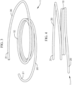
- the docking device 1 includes a coil with a plurality of turns extending along a central axis of the docking device 1.
- the coil can be continuous and can extend generally helically, with various differently sized and shaped sections, as described in greater detail below.
- the docking device 1 shown in Figs. 3 to 5 is configured to best fit at the mitral position, but can be shaped similarly or differently in other embodiments for better accommodation at other native valve positions as well.
- the coils of the central region 10 can also be referred to as the "functional coils," since the properties of these coils contribute the most to the amount of retention force generated between the valve prosthesis, the docking device 1, and the native mitral leaflets and/or other anatomical structures.
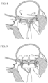
- the docking device 1 can be advanced through a distal end of the delivery catheter 1010 positioned in the left atrium (e.g., positioned at a commissure), through the native mitral annulus, for example, at a commissure of the native mitral valve, and into the left ventricle.
- the distal end of the docking device 1 then circles around the mitral anatomy (e.g., native mitral leaflets and/or the chordae tendineae) located in the left ventricle, so that all or at least some of the native leaflets and/or the chordae tendineae are corralled or gathered by and held in (e.g., encircled by) the coils of the docking device 1.
- mitral anatomy e.g., native mitral leaflets and/or the chordae tendineae
- the stabilization coil/turn (e.g., atrial coil) of the upper region 30 can still be substantially circular, and/or the stabilization coil/turn can be biased in one direction, such that a center of the upper region is offset from the center of other portions of the docking device.
- This biasing of the shape of the upper region 30 of the docking device 1 can, for example, increase contact between the docking device 1 and the wall of the left atrium or other anatomy in the radial direction that the upper region 30 extends farthest from other portions of the docking device 1.
- the stabilization coil/turn e.g., atrial coil
- the stabilization coil/turn can be biased such that when viewed from a bird's eye view ( Fig.
- the docking device 1 can be more securely held or retained at a proper positioning and orientation at the native valve annulus (e.g., native mitral annulus) before the THV is implanted and expanded therein.
- the native valve annulus e.g., native mitral annulus
- Such self-retention of the docking device 1 will more effectively prevent undesirable shifting or tilting of the docking device 1 before the prosthetic valve is fully implanted, thereby improving performance of the implant as a whole.
- the delivery catheter 1010 is advanced to a position in the left atrium where the distal end of the delivery catheter 1010 is just above a plane of the native valve (e.g., the mitral plane) and can be positioned, for example, near a commissure of the native valve.
- the delivery catheter can be steerable in multiple dimensions (e.g., more than two dimensions) to allow more precise positioning.
- the positioning of the distal opening of the delivery catheter defines an access site for implanting the docking device 1 at the mitral position.
- the extension 140 also raises a position of the upper region 130, so that the contact that the upper region 130 makes against the atrial wall can be elevated or spaced farther away from the native valve, which could, for example, also reduce stresses on and around the native valve, as well as provide for a more secure holding of the position of the docking device 100.
- the extension 140 can have a length ranging from 5 to 100 mm, and in one embodiment is 15 mm.
- the docking device 100 can further include one or more through holes 150 at or near one or both of the proximal and distal ends of the docking device 100.
- the through holes 150 can serve, for example, as suturing holes for attaching a cover layer over the coil of the docking device 100, and/or for example, as an attachment site for delivery tools, such as a pull wire/suture for a pusher, a holding device/anchor (e.g., for holding the docking device and/or allowing retraction and retrievability of the device after being fully or partially deployed from the delivery catheter), or other advancement device or retention device.
- a width or thickness of the coil of the docking device 100 can also be varied along the length of the docking device 100.
- a central region of the docking device 100 can be made slightly thinner than end regions of the docking device 100 (not shown), so that for example, the central regions exhibit greater flexibility, the end regions are stronger or more robust, and/or the end regions provide more surface area for suturing or otherwise attaching a cover layer to the coil of the docking device 100, among other reasons.
- all or a portion of extension 140 can have a thickness that is less than the thickness in other regions of the docking device, e.g., extension 140 can be thinner than the leading coil/turn or lower region 120, thinner than the functional coils/turns or central region 110, and/or thinner than the stabilization coil/turn or upper region 130, e.g., as shown, for example, in Fig. 19 .
- the docking device should be placed high relative to the native mitral valve (e.g., farther into the left atrium).
- the finally implanted dock and valve combination should be placed high at the native valve, in some cases as high as possible, to anchor the valve to a clear zone of the native mitral leaflets.
- the native mitral leaflets are generally smoother above the coaptation line (e.g., above where the leaflets come together when the mitral valve is closed) and rougher below the coaptation line.
- the smoother area or zone of the native leaflets are much more collagenous and stronger, thereby providing a more secure anchoring surface for the prosthetic valve than the rougher area or zone.
- the docking device should be placed as high as possible at the native valve during insertion, while also having sufficient retention force to anchor the prosthetic valve or THV.
- the length of the coil in the docking device placed in the ventricle generally depends on the number of turns in the ventricle and the thickness of the wire used. Generally, the thinner the wire used, the more length is required in the ventricle to provide sufficient retention force. For example, if a docking device coil has a length of 370 mm, then about 280 mm (e.g., ⁇ 2 mm) would be placed in the ventricle. About 70 to 90 mm would be placed in the atrium, and about 10-15 would be used in the transition or extension length to move the docking device coils away from the plane of the mitral valve on the atrial side of the docking device.
- Figs. 11 to 13 show a docking device according to another embodiment of the invention.
- the docking device 200 (see Figs. 12 and 13 ) is formed with a laser-cut tube 210 and a tensioning wire 219.
- the wire 219 can be used to adjust the curvature and/or size of the docking device 200.
- the docking device 200 can assume a larger or wider configuration when being positioned at the native valve annulus, and can thereafter be adjusted with the wire 219 to assume a smaller or narrower configuration to prepare for docking a prosthetic valve.
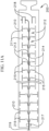
- Fig. 11 schematically shows an open sheet view of a laser-cut tube 210, e.g., the ends of the sheet can be connected to form a tubular structure, or a similar tube can be formed as a tube and cut as a tube, i.e., without a seam.
- the tube 210 can be made from either shape memory or non-shape memory material (e.g., NiTi, stainless steel, other materials, or a combination of materials).
- the tube 210 can be laser cut with the pattern shown in Fig. 11 , or with a similar pattern, where the cutting pattern dictates the shape of the docking device 200 when the docking device 200 is actuated.
- the laser-cut sheet or tube can include one or more distal wire lock features, for example, cut 217 at a distal or left end of the sheet or tube as illustrated, and/or one or more proximal wire lock features, for example, cuts 218 at the proximal or right end of the sheet or tube as illustrated.
- a locking wire 219 illustrated in Fig. 11A , can be attached to the distal or proximal end of the tube 210, and can then be tensioned through the tube 210 and locked at the opposite end of the tube 210 in order to effect a desired actuated shape of the docking device 200.
- the tube 210 By having laser cut patterns positioned along a large portion of or along the entire length of the tube 210, when the locking wire 219 is attached at one end of the tube 210 and is then actuated and locked to the other end of the tube 210, the tube 210 is forced into a desired final coil form or shape by virtue of the arrangement of the cuts 211 and 216.
- the tension in the tensioning wire has the ability to control the radial outward and inward forces applied onto the docking device 200, and by the docking device 200 onto other features, for example, on a replacement valve 40 held therein.
- the locking wire can assist in controlling the forces applied by the docking device, but in other embodiments, a locking wire is not required.
- the locking wire can be in a laser-cut hypotube, or the locking wire can be in a tube that is not laser cut.
- the locking wire can be a suture, tether, wire, strip, etc., and the locking wire can be made of a variety of materials, e.g., metal, steel, NiTi, polymer, fiber, Dyneema, other biocompatible materials, etc.
- the distal tip 222 of the tube 210 can be shape set differently, so that instead of following the same coil shape as the rest of the docking device 200, the distal tip 222 flexes or articulates slightly radially outwardly compared to other portions of the docking device 200, for example, as can be seen in Fig. 12 , in order to further assist in helping to encircle the mitral anatomy or other valve anatomy.
- the distal end 222 of the tube 210 can include different cuts 216 in order to make the distal end 222 more flexible or mobile, which can also assist in navigating the distal end 222 of the docking device 200 around the anatomical geometry.
- the docking device 200 can be modified in various ways in other embodiments.
- the docking device can be made from or include shape memory materials other than NiTi, or in some embodiments can be made from non-shape memory materials, such as stainless steel, from other biocompatible materials, and/or a combination of these.
- shape memory materials other than NiTi
- non-shape memory materials such as stainless steel
- a similar or slightly modified docking device can also be used to dock replacement valves at other native valve sites, for example, at the tricuspid valve, pulmonary valve, or at the aortic valve.
- the docking device 200 described above, and similar devices using a tensioning or locking wire, can provide several advantages over other docking devices, such as devices where a locking wire is not used.
- the locking wire provides a user with the ability to control an amount of the radial outward and inward forces applied on and by the docking device through effecting and adjusting the tension in the locking wire, without compromising a desired profile of the docking device or the ability to deliver the docking device through a catheter or via minimally invasive techniques.
- Figure 11A illustrates a tensioning wire 219 that is held below the teeth 218 or looped around teeth 218, then pulled through the opening 217 and crimped at the opening 217 to set the shape of the docking device.
- the laser cuts in the tube make the docking device more flexible, enabling the docking device to be introduced through catheters that may have relatively small bend radii at certain locations.
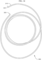
- the docking device 300 in Fig. 14 includes a main coil 310 (which can be similar in size and shape to one of the docking devices described above) and anchors 320 extending from the two free ends of the coil 310.
- the anchors 320 are sized, shaped, or otherwise configured to embed themselves into the surrounding tissue (e.g., into the atrial and/or ventricular walls), for example, when a replacement valve is expanded in the docking device 300.
- the anchors 320 can be barbed to promote ingrowth once the anchors 320 are embedded into the heart walls or other tissue.
- the anchors can be any of many different shapes and sizes.
- the anchors can extend from the end or from any area near the end.
- anchors or barbs can also be positioned at various locations along the length and outer surface of the docking device.
- the docking device 300 In operation, when the docking device 300 is deployed at the mitral anatomy, once the docking device 300 is positioned through the mitral valve, one end of the docking device 300 is positioned in the left atrium while the other end of the docking device 300 is positioned in the left ventricle.
- the shape and size of the coil 310 of the docking device 300 can be selected and optimized to ensure that the ends of the coil 310 respectively abut against the atrial and ventricular walls when the docking device 300 is advanced to the desired position.
- the anchors 320 at the ends of the coil 310 can therefore anchor themselves into the respective heart walls. When the replacement valve is expanded in the coil 310, the free ends of the coil 310 are held in position by the anchors 320 being lodged in the heart walls.
- the inability of the free ends of the coil 310 to move when the replacement valve is expanded in the docking device 300 prevents the coil 310 from unwinding, thereby increasing the radial forces applied between the docking device 300 and the expanded valve and improving the retention force between the components.
- the covering 420 can be made from one or more other high friction materials that covers the coil 410 in a similar manner.
- the material or materials selected for making the covering 420 can also promote rapid tissue ingrowth.
- an outer surface of a frame of the replacement valve can also be covered in a cloth material or other high friction material to further increase the friction force between the docking device and the valve, thereby further reducing or preventing the docking device from unwinding.
- the friction provided by the covering can provide a coefficient of friction greater than 1.
- the covering can be made of ePTFE and can be a tube that covers the coil, and can be smooth or can have pores (or be braided or have other structural features that provide a larger accessible surface area like pores do) to encourage tissue ingrowth.
- the covering can also have a PET braid over the ePTFE tube when the ePTFE tube is smooth.
- the outermost surface of the covering or braid over the covering can be any biocompatible material that provides friction, such as a biocompatible metal, silicone tubing, or PET. Pore size in the covering can range from 30 to 100 microns.
- the PET layer is only attached to the ePTFE covering, and not directly to the coil of the docking device.
- the ePTFE tube covering can be attached to the docking device coil at the coverings proximal and distal ends. It can be laser welded on to the coil, or radiopaque markers can be placed on the outside of the ePTFE tube covering or PET braid and swaged to the materials to hold them in place to the coil.
- Figs. 16 and 16A schematically show a portion of yet another modified docking device that improves retention forces between the docking device and a replacement valve.
- the valve leaflet tissue 42 undulates to conform to the varying cross-section between the areas of the coil 510 with frictional elements 510 and without the frictional elements. This undulating of the leaflet tissue 42 results in a more secure entrapment of the tissue 42 between the docking device 1 and the valve frame 41.
- the docking device 500 in Fig. 16 includes a main coil 510 and one or more discrete friction elements 520 that are spaced apart along a length of the coil 510.
- Fig. 18 schematically shows parts of three turns of still another modified docking device 600 that helps improve retention forces between the docking device and a replacement valve.
- the docking device 600 includes a coil 610 that is modified with one or more interlocking lock and key patterns spaced apart along the length of the coil 610.
- the lock and key patterns can be simple, for example, a rectangular groove or cutout 618 and a complementary rectangular projection 622, as generally illustrated in Fig. 18 , or can be made of or include different shapes and/or more complex patterns in other embodiments.
- the grooves 618 and projections 622 can all be arranged in a same axial direction or in different axial directions in varying embodiments.
- the lock and key patterns or other frictional elements can be placed on the functional turns of the docking device.
- the lock and key mechanism When an expandable valve is expanded in the docking device 600, the lock and key mechanism relies on adjacent turns of the coil 610 abutting against one another and on each turn interlocking with adjacent turns of the coil 610 located above and/or below it when one or more of the projections 622 engage corresponding grooves 618.
- the interlocking of the grooves 618 and the projections 622 prevents relative motion between the respective features, consequently also preventing the coil 610 of the docking device 600 from physically unwinding. Therefore, this arrangement also serves to increase the radial forces and the final retention force between the docking device 600 and a replacement valve that is expanded in the docking device 600.
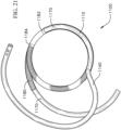
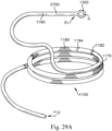
- Fig. 19 shows a perspective view of an exemplary anchor or docking device.
- the docking device 1100 in Fig. 19 can be the same as or similar in structure to the docking device 100 in Fig. 10 described above and can include any of the features and characteristics described with respect to docking device 100.
- Docking device 1100 can also include a central region 1110, a lower region 1120, an upper region 1130, and an extension region 1140.
- the lower and upper regions 1120, 1130 can form larger coil diameters than the central region 1110, and the extension region 1140 can space the upper region 1130 apart from the central region 1110 in a vertical direction, also similarly as previously described.
- the docking device 1100 is also arranged or wound so that advancement of the docking device 1100 into the left ventricle can be performed in a counter-clockwise manner viewing the annulus in the outflow direction (e.g., from atrium to ventricle). Other embodiments may instead facilitate clockwise advancement and placement of the docking device.
- the central coils/turns 1110 of the docking device 1100 also serve as the functional coils/turns, and provide a main docking site for a prosthetic valve or THV that is expanded therein.
- the central turns 1110 will generally be positioned in the left ventricle, while a small distal portion, if any, will extend through the native valve annulus and into the left atrium, described in greater detail below.
- the lower region 1120 of the docking device 1100 serves as a leading coil/turn (e.g., a ventricular encircling turn).
- the lower region 1120 includes the distal tip of the docking device 1100, and flares radially outwardly from the central turns 1100, in order to capture the native valve leaflets, and some or all of the chordae and/or other mitral anatomy, when the docking device 1100 is advanced into the left atrium.
- Native mitral valves exhibiting mitral regurgitation typically measure about a 35 mm A2P2 distance and a 45 mm distance from commissure to commissure.
- the lower region 1120 is formed to have an enlarged size or profile compared to the central turns 1110, in order to initially guide the docking device 1100 more easily around both of the native valve leaflets.
- the diameter of the lower region 1120 can be constructed to be about the same as the distance measured between the commissures of the native valve (e.g., 45 mm), such that the distal tip will extend approximately that distance away from the outlet of the delivery catheter during delivery of the docking device 1100.
- the upper region 1130 of the docking device 1100 serves as the stabilization coil/turn (e.g., atrial coil/turn) that provides the docking device 1100 with a self-retention mechanism during the transition phase after the docking device 1100 is deployed at the native valve and prior to delivery of the THV.
- the left atrium generally flares outwardly from the mitral annulus, forming a funnel-like shape that widens away from the annulus.
- the diameter of the upper region 1130 is selected to allow the upper region 1130 to fit at an approximate desired height in the left atrium, and to prevent the upper region 1130 from sliding or dropping further towards the native mitral annulus after the desired position is achieved.
- the upper region 1130 is formed to have a diameter from 40-60 mm, such as a diameter of about 53 mm.
- Fig. 20 is a schematic top view of a portion of a heart, showing an approximation of the left atrium 1800, and the mitral valve 1810 positioned at a central region thereof.
- an approximate position of the aorta 1840 is also schematically illustrated.
- a docking device 1100 has been delivered to the native mitral valve 1810 at commissure A3P3 1820.
- the extension region 1140 provides a vertical extension and spacing between the central region 1110 and the upper region 1130 of the docking device 1100.
- the extension region 1140 of the docking device 1100 (and extension 140 of docking device 100) can therefore be referred to as an ascending turn.
- the location at which the docking device 1100 crosses the mitral plane is important in preserving the integrity of the native valve anatomy, and specifically the valve leaflets and commissures, to serve as an appropriate docking site for the final implantation of the THV.
- the extension region 1140 of the docking device 1100 can also have a smaller diameter cross-section.
- the wire core of other regions of the docking device 1100 can have a diameter of, for example, 0.825 mm, while the core of the extension region 1140 can have a diameter of 0.6 mm.
- the wire core of other regions of the docking device has a cross section diameter of 0.85 mm, and the extension region has a cross-section diameter of 0.6 mm.
- the extension region 1140 can have a cross-section diameter of 0.4 to 0.8 mm.
- the thicknesses can also be chosen based on a ratio to one another.
- the extension region can have a cross-section diameter that is 50% to 75% of the cross-section diameter of the rest of the portions of the wire.
- An extension region 1140 with a smaller cross-section can allow for a sharper angle of ascension of the extension region 1140 from the mitral plane.
- the radius of curvature and the wire cross-section of the extension region 1140 can further be selected, for example, to provide a sufficient connection point between the central region 1110 and the upper region 1130 of the docking device 1100, and/or to allow the extension region 1140 to be deployed and retrieved more easily with smaller forces during delivery, since a thinner wire core is generally easier to straighten and bend.
- the thicknesses of both the extension region 1140 and the rest of the docking device 1100 should be chosen so as not to exceed any strain limits, based on the material properties of the material or materials selected.
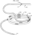
- a wire core of the docking device 1100 can be made of NiTi, another shape memory material, or another biocompatible metal or other material, the wire core can be covered by one or more additional materials. These cover or layer materials can be attached in a variety of ways including, for example, adhesion, melting, molding, etc. around the core or otherwise suturing, tying, or binding the cover/layer to the wire core. Referring briefly to Fig. 22 , a cross-section of a distal portion of the docking device 1100 includes a wire core 1160 and a cover layer 1170. The wire core 1160, for example, can provide strength to the docking device 1100.
- a base material of the cover layer 1170 which covers the wire core 1160 can be, for example, ePTFE or another polymer.
- the cover layer 1170 can be more compressive than the wire core 1160, so that the wire frame and/or struts of the THV can partially dig into or otherwise anchor into the cover layer 1170 for added stability when the THV is expanded in the docking device 1100.
- a more compressible material will also allow the pinching or compression of the native valve leaflets and other anatomy between the docking device 1100 and the THV to be less traumatic, leading to less wear and/or damage to the native anatomy.
- ePTFE the material is also not water or blood permeable, but will allow ethylene oxide gas to pass or penetrate through, thereby providing a layer through which the underlying wire core 1160 can be more easily sterilized.
- an ePTFE cover layer 1170 can be constructed with, for example, a 30 micron pore size, to facilitate easy anchoring of blood cells in and against the outer surface of the cover layer 1170, for example, to promote in-growth of tissue after implantation.
- ePTFE is also a very low friction material.
- a docking device 1100 with an ePTFE cover layer 1170 will provide for stability and promote in-growth.
- the functional coils/turns or central region 1110 of the docking device 1100 is generally the only region where a high friction covering/layer is desired, as seen in Fig. 19 , the braid layer or high friction covering/layer 1180 does not extend into either the lower region 1120 or the extension region 1140, so that those regions of the docking device 1100, along with the upper region 1130, remain low friction, in order to facilitate less traumatic interactions with the native valve and other heart anatomy. Additional friction elements and thus improvement in retention forces between the docking device and a replacement valve, can also be added to the device through any combination of the high friction covering/layer 1180 and high friction elements or other features described herein and illustrated in Figs. 15-18 .
- Fig. 20 shows a top view of a possible placement of the docking device 1100 at the native mitral valve 1810 prior to expansion of a THV therein.
- the docking device 1100 is advanced counterclockwise through commissure A3P3 1820 of mitral valve 1810 and into the left ventricle.
- a correct positioning of the docking device 1100 can be very important.
- the docking device 1100 should be positioned relative to the native valve 1810 such that a desired part of the docking device 1100 extends through the native valve 1810 at or near commissure A3P3, and comes into contact with the atrial side of the native leaflets.
- a proximal portion of the central region 1110 of the docking device 1100 extends between the proximal end of the covering or braid layer 1180 and the extension region 1140, where the ePTFE or low friction layer 1170 remains exposed.
- a cover layer that covers the skeleton/core 710 of the docking device can be, for example, one or more of the coverings or layers (e.g., low friction and/or high friction covering(s)) previously described.
- the cover layer can be made of or include, for example, an ePTFE core tube that is wrapped with a woven PET cloth, or can be made of or include any other fabric or other biocompatible material.
- Such a cover layer can be used to cover a majority of the docking device, for example, from a main body of the coil skeleton/core 710 up to or slightly over the end 718 of the tip 712.
- the tip construction and arrangements prevent exposure of any sharp edges, and also prevent surfaces of the skeletons 710, 810 from cutting and/or protruding out of the cover layers, as a result of any friction forces that are applied to the cover layers of the docking devices during or after delivery.
- the covering/cover layer 920 can be, for example, a covering, fabric layer, or other layer the same as or similarly constructed as discussed above with respect to previous embodiments of the docking device.
- the covering/cover layer 920 is wrapped around the coil skeleton/core 910, and is anchored to or otherwise secured to the coil/core 910 by sutures 930 that run along and are passed through the slit hole 912.
- the sutures 930 can be crossed through the slit hole 912 in an "8" shape, as shown in Fig.
- the sutures 930 are positioned at or moved towards a proximal portion of the slit hole 912, near the free end 918 of the coil skeleton/core 910, so that a distal end of the slit hole 912 remains exposed and accessible to a user, and stays open and large enough, for example, for a pull wire 940 (e.g., a release/retrieval suture) of a pusher of the delivery catheter to pass or cross through, thereby establishing a secure connection between the docking device 900 and the pusher.
- the pull wire 940 can be a suture.
- the shape and structure at the end of the coil skeleton/core 910, the type, texture, and construction of the covering/cover layer 920, and the connection technique (e.g., suturing technique) for attaching the covering/cover layer 920 to the coil skeleton/core 910 each contributes to a tight connection between the end of the coil 910 and the covering/cover layer 920, and can be done with or without the use of glue or any other adhesives (e.g., the suturing technique does not require these).
- Embodiments of docking devices herein have generally been discussed above with respect to helping anchor replacement valves at the mitral position.
- the docking devices as described or slightly modified versions thereof, can also be applied in similar manners to valve replacements at other valve sites as well, for example, at the tricuspid, pulmonary, or aortic positions.
- Patients that are diagnosed with insufficiencies at either position can exhibit enlarged annuli that both prevent the native leaflets from properly coapting, and that also can cause the annuli to become too large, too soft, or too otherwise diseased to securely hold an expandable valve therein. Therefore, use of a rigid or semi-rigid docking device can also be beneficial for anchoring a replacement valve at those valve sites as well, for example, to prevent the replacement valves from dislodging during normal heart function.
- the docking devices herein can further be covered with one or more coverings or cover layers, similarly as discussed above.
- cover layer(s) for any of these applications can also be made of or include a material that promotes more rapid tissue ingrowth.
- the cover layer can further be constructed to have a larger amount of surface area, for example, with a velour film, porous surface, braided surface, etc., to further bolster tissue ingrowth.
- a possible access point for tricuspid replacement can be, for example, transseptal access
- a possible access point for aortic replacement can be, for example, transfemoral access, although access to the respective valve sites is not limited thereto.
- coil-shaped docking devices as previously described at the other valve sites can also serve to circumferentially cinch or clamp the native leaflets after deployment of the replacement valve at the native annulus, for example, by virtue of the leaflets and other tissue being sandwiched between coils of the docking device and being held in place by a spring force of the docking device, which further prevents slipping or other movement of the docking device and of the sandwiched tissue relative to the docking device, and prevents unwanted growth or expansion of the native annulus over time.
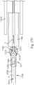
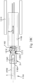
- Some possible attachment configurations between the anchor/docking device and the release or retrieval line/suture and movement and/or sliding of the components might sometimes result in the anchor/docking device T-ing or "T-boning" with the pusher tube and/or delivery catheter, e.g., such that the axis of the pusher tube and/or delivery catheter is not aligned (and can be perpendicular) with the axis of a proximal end of the anchor/docking device.
- pulling on the retrieval line/suture may result in the end portion 2700 of the docking device and the pusher device/tube 1165 and/or delivery catheter moving to an orthogonal or substantially orthogonal relative orientation, rather than an aligned orientation, e.g., they could become relatively oriented to form the shape of a "T". If this happens, it can be difficult to retrieve or withdraw the anchor/docking device back into the delivery catheter.
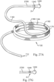
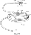
- any of the anchors/docking devices described herein can be configured such that a line of force F applied by a retrieval suture/line 1163 can be biased to be aligned with or substantially aligned (or biased toward alignment) with a central axis or area moment of inertia A of an end portion 2700 of the docking device (See Figure 27C ).
- This alignment can help inhibit and/or prevent the end portion 2700 of the docking device from relatively sliding or moving to one side of the pusher device or tube 1165 when the retrieval suture pulls the end portion 2700 of the docking device against the pusher device and/or when the docking device is pulled into the delivery catheter.
- the docking device 1100 When tension is put on the release/retrieval suture 1163, such as when attempting to retrieve the docking device 1100, the docking device 1100 will generally follow the line of the tension as the docking device 1100 moves toward the pusher tube 1165 and/or delivery catheter. Some configurations may sometimes result in the end portion 2700 moving or sliding to the "T" orientation described above. For example, in some potential configurations, if the suture release holes 1162 are oriented radially outward on the docking device 1100, the line tension force F from the release suture 1165 to the end portion 2700 may not be aligned with the axis or area moment of inertia A of the end portion 2700 of the anchor/docking device.
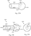
- the docking device 1100 may be provided with a connection end/tip or spherical end/tip 1200 which can be integral with, molded, or machined on the end of the coil/core 1160 of the docking device 1100 or a cap that is attached to the proximal end of the coil/core 1160 by sutures, welding, adhesive, or other methods known in the art.
- the spherical portion 1202 is substantially in the shape of a sphere or ball and the neck portion 1206 can be shaped and sized to either be a continuation of the coil/core 1160 of the docking device 1100 or to fit as a cap over the proximal end of the coil/core 1160.
- the transition portion 1204 provides a gradual and smooth transition between the larger diameter of the spherical portion 1202 and the smaller diameter of the neck portion 1204.
- the spherical proximal tip 1200 can have a wide variety of different shapes and sizes.
- the side passages 1212 define a pair of openings in the exterior of the spherical proximal tip 1200.
- the side passage openings are positioned at a point substantially where the spherical portion 1202 and transition portion 1204 converge.
- the side passage openings can be provided at a wide variety of different locations.
- the side passages 1212 meet and open into the central passage 1210 at substantially the center of the spherical portion 1202.
- the central passage 1210 and side passages 1212 can define a smooth, forked passage.
- the edges of the openings of the passages 1210, 1212 and/or the intersections of the passages 1212 with the passage 1210 can be smoothed or rounded.
- the central passage biases a suture passing therethrough to be aligned with (or toward alignment with) the central or longitudinal axis of the tip 1200 and end portion of the docking device.
- the tip/end 1200 can include a covering(s) thereover.
- the spherical tip 1200 has been described as having a central passage 1210 and two side passages 1212, it will be appreciated that other designs are contemplated.
- the tip 1200 can include a central opening at the proximal end of the tip 1200 and two angled passages can extend directly therefrom. The two angled passages can both open into the central opening and extend distally and radially outwardly therefrom.
- one end of the retrieval or release suture/line 1163 is threaded through the central passage 1210 and one of the side passages 1210, around an outer surface of the tip 1200, into and through the other side passage 1210, and out through the central passage 1210. Threaded in such a manner, both ends of the suture/line 1163 extend from a proximal and central portion of the spherical connection tip 1200 such that the line of tension or force F applied by the suture/line 1163 on the tip 1200 is in-line with the longitudinal axis A of the end portion 2700 and the axis AT of the central passage of the tip 1200.
- the spherical proximal tip/end 1200 can optionally include a bore 1230 in the distal end of the tip 1200 to receive the proximal end of the coil/core 1160 of the docking device 1100.
- the bore 1230 terminates at a bore base 1232.
- the bore base 1232 can abut the proximal end of the inserted coil/core 1160.
- the bore base 1232 can be cylindrical, conical, or another shape.
- the spherical proximal tip 1200 can optionally include an eyelet 1240 or slot in the neck portion 1206 which extends through the tip/end 1200. A suture can be passed through the eyelet 1240 and through a hole 1162 (See Fig.
- the spherical connection tip/end 1200 can be integral with the docking device 1100, can be machined onto the proximal end of the docking device 1100, or can be a cap which is attached to the proximal end of the docking device by sutures, welding, or other attachment means.
- the location of the central and side passages 1210, 1212 allow for thicker walls which make the spherical tip/end 1200 more robust.
- the spherical tip 1200 can be configured and designed such that the distal portion is larger in diameter than the end portion 2700 of the docking device 1100 ( Fig. 27A ) or such that the distal portion is flush with the end portion 2700 ( Fig. 27G ).
- the tip/end 1200 can be integral with the docking device such that it does not require a bore 1230 or bore base 1232, or the proximal end of the end portion 2700 can be reduced in diameter, such as by machining, to be receivable in the bore 1230 of the spherical proximal tip 1200 when the distal portion of the tip 1200 is to be flush with the end portion 2700 of the docking device.
- Other methods of fitting the spherical proximal tip 1200 flush with the end portion 2700 of the docking device 1100 are also contemplated.
- the spherical connection tip/end can be made in a wide variety of different ways.
- the spherical tip/end 1200 can be made by zapping (e.g. electric discharge machining) the proximal end of the tip/end 1200 to create a sphere.
- the central and side passages 1210, 1212 can be formed by laser or micro-machining. Electropolishing can be used to create the radius on the edges.
- the spherical tip/end 1200 can be made of Nitinol.
- the tip/end 1200 can be made from other materials, such as PEEK (Polyether ether ketone), ultem or other polyetherimides, stainless steel, shape memory metal or material other than Nitinol, and/or other non-shape memory materials or any other material known in the art.
- PEEK Polyether ether ketone
- ultem or other polyetherimides stainless steel
- shape memory metal or material other than Nitinol and/or other non-shape memory materials or any other material known in the art.
- the spherical tip/end can be constructed to withstand 130 Newtons of force F applied by the suture without bending or breaking.
- the central passage 1210 can have a circular opening, an oval opening, a conical opening, a square opening, etc.
- the central passage 1210 has an oval opening to the proximal portion of the tip 1200.
- the oval opening can have a small size, such as an opening with a width between 0.95 and 1.30 mm, such as between about 1.03 and 1.23 mm, such as about 1.13 mm, and a height between 0.50 and 0.85 mm, such as between about 0.55 and 0.77 mm, such as about 0.65 mm.
- the side passages can have a wide variety of different shapes.
- the side passages 1212 have round openings with a diameter between 0.50 and 0.85 mm, such as between about 0.55 and 0.75 mm, such 0.65 mm.
- the axis extending through each side passage 1212 can be at an angle between 115 and 135°, such as between about 120 and 130°, such as about 126°, from the longitudinal access extending through the central passage 1210.
- the edge between the bore 1230 and the bore base 1232 can be rounded.
- the rounded edge can have a radius between about 0.1 and 0.4 mm, such as about 0.20 mm.
- the bore 1230 can extend between 1.9 and 2.35 mm, such as between about 2.01 and 2.21 mm, such as about 2.11 mm, proximally into the tip 1200 from the distal end.
- the eyelet 1240 is shaped with two semi-circles on either side of a rectangular portion.
- the rectangular portion of the eyelet 1240 can be between 0.40 and 0.47 mm long, such as between about 0.46 and 0.66 mm, such as about 0.56 mm.
- the semi-circular portions of the eyelet 1240 can have a radius between 0.125 and 0.25 mm, such as between about 0.15 and 0.20 mm, such as about 0.17 mm.
- the distance from the distal end of the rectangular portion of the eyelet 1240 to the distal end of the spherical proximal tip 1200 can be between 0.7 and 1.1 mm, such as between about 0.8 mm and 1.0 mm, such as about 0.9 mm.
Landscapes
- Health & Medical Sciences (AREA)
- Cardiology (AREA)
- Engineering & Computer Science (AREA)
- Biomedical Technology (AREA)
- Life Sciences & Earth Sciences (AREA)
- Transplantation (AREA)
- Heart & Thoracic Surgery (AREA)
- Vascular Medicine (AREA)
- Oral & Maxillofacial Surgery (AREA)
- Animal Behavior & Ethology (AREA)
- General Health & Medical Sciences (AREA)
- Public Health (AREA)
- Veterinary Medicine (AREA)
- Mechanical Engineering (AREA)
- Prostheses (AREA)
- External Artificial Organs (AREA)
- Materials For Medical Uses (AREA)
Applications Claiming Priority (3)
| Application Number | Priority Date | Filing Date | Title |
|---|---|---|---|
| US15/902,956 US10722359B2 (en) | 2016-08-26 | 2018-02-22 | Heart valve docking devices and systems |
| EP18907294.5A EP3755269A4 (de) | 2018-02-22 | 2018-02-23 | Herzklappenandockvorrichtungen und -systeme |
| PCT/US2018/019545 WO2019164516A1 (en) | 2018-02-22 | 2018-02-23 | Heart valve docking devices and systems |
Related Parent Applications (1)
| Application Number | Title | Priority Date | Filing Date |
|---|---|---|---|
| EP18907294.5A Division EP3755269A4 (de) | 2018-02-22 | 2018-02-23 | Herzklappenandockvorrichtungen und -systeme |
Publications (2)
| Publication Number | Publication Date |
|---|---|
| EP4397279A2 true EP4397279A2 (de) | 2024-07-10 |
| EP4397279A3 EP4397279A3 (de) | 2024-08-14 |
Family
ID=67688534
Family Applications (2)
| Application Number | Title | Priority Date | Filing Date |
|---|---|---|---|
| EP24177295.3A Pending EP4397279A3 (de) | 2018-02-22 | 2018-02-23 | Herzklappenandockvorrichtungen und -systeme |
| EP18907294.5A Pending EP3755269A4 (de) | 2018-02-22 | 2018-02-23 | Herzklappenandockvorrichtungen und -systeme |
Family Applications After (1)
| Application Number | Title | Priority Date | Filing Date |
|---|---|---|---|
| EP18907294.5A Pending EP3755269A4 (de) | 2018-02-22 | 2018-02-23 | Herzklappenandockvorrichtungen und -systeme |
Country Status (13)
| Country | Link |
|---|---|
| US (2) | US10722359B2 (de) |
| EP (2) | EP4397279A3 (de) |
| JP (3) | JP7177162B2 (de) |
| KR (2) | KR102742062B1 (de) |
| CN (2) | CN111970993B (de) |
| AU (2) | AU2018409826B2 (de) |
| BR (2) | BR112020016300B1 (de) |
| CA (1) | CA3090478A1 (de) |
| IL (2) | IL276763B2 (de) |
| MX (3) | MX2020008522A (de) |
| NZ (1) | NZ766755A (de) |
| SG (1) | SG11202007778XA (de) |
| WO (1) | WO2019164516A1 (de) |
Families Citing this family (97)
| Publication number | Priority date | Publication date | Assignee | Title |
|---|---|---|---|---|
| US8870950B2 (en) | 2009-12-08 | 2014-10-28 | Mitral Tech Ltd. | Rotation-based anchoring of an implant |
| US20110224785A1 (en) | 2010-03-10 | 2011-09-15 | Hacohen Gil | Prosthetic mitral valve with tissue anchors |
| US9763657B2 (en) | 2010-07-21 | 2017-09-19 | Mitraltech Ltd. | Techniques for percutaneous mitral valve replacement and sealing |
| US11653910B2 (en) | 2010-07-21 | 2023-05-23 | Cardiovalve Ltd. | Helical anchor implantation |
| US10500038B1 (en) | 2011-05-20 | 2019-12-10 | Tel Hashomer Medical Research Infrastructure And Services Ltd. | Prosthetic mitral valve, and methods and devices for deploying the prosthetic mitral valve |
| WO2013021374A2 (en) | 2011-08-05 | 2013-02-14 | Mitraltech Ltd. | Techniques for percutaneous mitral valve replacement and sealing |
| US8852272B2 (en) | 2011-08-05 | 2014-10-07 | Mitraltech Ltd. | Techniques for percutaneous mitral valve replacement and sealing |
| EP3417813B1 (de) | 2011-08-05 | 2020-05-13 | Cardiovalve Ltd | Perkutaner mitralklappenersatz |
| EP3705090B1 (de) * | 2011-08-11 | 2023-12-06 | Tendyne Holdings, Inc. | Verbesserungen für prothesenklappen und damit zusammenhängende erfindungen |
| LT2852354T (lt) | 2012-05-20 | 2020-09-25 | Tel Hashomer Medical Research Infrastructure And Services Ltd. | Mitralinio vožtuvo protezas |
| EP2948103B1 (de) | 2013-01-24 | 2022-12-07 | Cardiovalve Ltd | Ventrikulär verankerte klappenprothesen |
| EP3174502B1 (de) | 2014-07-30 | 2022-04-06 | Cardiovalve Ltd | Vorrichtung zur implantation einer knickbaren klappenprothese |
| EP3253333B1 (de) | 2015-02-05 | 2024-04-03 | Cardiovalve Ltd | Klappenprothese mit axial gleitendem rahmen |
| US11833034B2 (en) * | 2016-01-13 | 2023-12-05 | Shifamed Holdings, Llc | Prosthetic cardiac valve devices, systems, and methods |
| US10531866B2 (en) | 2016-02-16 | 2020-01-14 | Cardiovalve Ltd. | Techniques for providing a replacement valve and transseptal communication |
| US20190231525A1 (en) | 2016-08-01 | 2019-08-01 | Mitraltech Ltd. | Minimally-invasive delivery systems |
| CN109789018B (zh) | 2016-08-10 | 2022-04-26 | 卡迪尔维尔福股份有限公司 | 具有同轴框架的人工瓣膜 |
| US10575948B2 (en) | 2017-08-03 | 2020-03-03 | Cardiovalve Ltd. | Prosthetic heart valve |
| US10888421B2 (en) | 2017-09-19 | 2021-01-12 | Cardiovalve Ltd. | Prosthetic heart valve with pouch |
| US11793633B2 (en) | 2017-08-03 | 2023-10-24 | Cardiovalve Ltd. | Prosthetic heart valve |
| US12064347B2 (en) | 2017-08-03 | 2024-08-20 | Cardiovalve Ltd. | Prosthetic heart valve |
| US10537426B2 (en) | 2017-08-03 | 2020-01-21 | Cardiovalve Ltd. | Prosthetic heart valve |
| US11246704B2 (en) | 2017-08-03 | 2022-02-15 | Cardiovalve Ltd. | Prosthetic heart valve |
| US12458493B2 (en) | 2017-09-19 | 2025-11-04 | Cardiovalve Ltd. | Prosthetic heart valve and delivery systems and methods |
| GB201720803D0 (en) | 2017-12-13 | 2018-01-24 | Mitraltech Ltd | Prosthetic Valve and delivery tool therefor |
| GB201800399D0 (en) | 2018-01-10 | 2018-02-21 | Mitraltech Ltd | Temperature-control during crimping of an implant |
| WO2019195860A2 (en) | 2018-04-04 | 2019-10-10 | Vdyne, Llc | Devices and methods for anchoring transcatheter heart valve |
| US11234818B2 (en) * | 2018-05-21 | 2022-02-01 | Medtentia International Ltd Oy | Annuloplasty device |
| JP7421546B2 (ja) * | 2018-08-21 | 2024-01-24 | シファメド・ホールディングス・エルエルシー | 人工心弁デバイス、システム、および方法 |
| US11344413B2 (en) | 2018-09-20 | 2022-05-31 | Vdyne, Inc. | Transcatheter deliverable prosthetic heart valves and methods of delivery |
| US12186187B2 (en) | 2018-09-20 | 2025-01-07 | Vdyne, Inc. | Transcatheter deliverable prosthetic heart valves and methods of delivery |
| US10321995B1 (en) | 2018-09-20 | 2019-06-18 | Vdyne, Llc | Orthogonally delivered transcatheter heart valve replacement |
| US11071627B2 (en) | 2018-10-18 | 2021-07-27 | Vdyne, Inc. | Orthogonally delivered transcatheter heart valve frame for valve in valve prosthesis |
| US11278437B2 (en) | 2018-12-08 | 2022-03-22 | Vdyne, Inc. | Compression capable annular frames for side delivery of transcatheter heart valve replacement |
| US10595994B1 (en) | 2018-09-20 | 2020-03-24 | Vdyne, Llc | Side-delivered transcatheter heart valve replacement |
| US10912644B2 (en) | 2018-10-05 | 2021-02-09 | Shifamed Holdings, Llc | Prosthetic cardiac valve devices, systems, and methods |
| JP7489975B2 (ja) * | 2018-10-19 | 2024-05-24 | シファメド・ホールディングス・エルエルシー | 調整可能な医療デバイス |
| US11109969B2 (en) | 2018-10-22 | 2021-09-07 | Vdyne, Inc. | Guidewire delivery of transcatheter heart valve |
| WO2020100050A1 (en) | 2018-11-14 | 2020-05-22 | Tel Hashomer Medical Research, Infrastructure And Services Ltd. | Atrioventricular valve repair |
| CA3118722A1 (en) | 2018-11-20 | 2020-05-28 | Edwards Lifesciences Corporation | Deployment tools and methods for delivering a device to a native heart valve |
| US11253359B2 (en) | 2018-12-20 | 2022-02-22 | Vdyne, Inc. | Proximal tab for side-delivered transcatheter heart valves and methods of delivery |
| US10653522B1 (en) | 2018-12-20 | 2020-05-19 | Vdyne, Inc. | Proximal tab for side-delivered transcatheter heart valve prosthesis |
| WO2020146842A1 (en) | 2019-01-10 | 2020-07-16 | Vdyne, Llc | Anchor hook for side-delivery transcatheter heart valve prosthesis |
| US11185409B2 (en) | 2019-01-26 | 2021-11-30 | Vdyne, Inc. | Collapsible inner flow control component for side-delivered transcatheter heart valve prosthesis |
| US11273032B2 (en) | 2019-01-26 | 2022-03-15 | Vdyne, Inc. | Collapsible inner flow control component for side-deliverable transcatheter heart valve prosthesis |
| CN113543750B (zh) | 2019-03-05 | 2025-10-10 | 维迪内股份有限公司 | 用于正交经导管心脏瓣膜假体的三尖瓣反流控制装置 |
| US10758346B1 (en) | 2019-03-14 | 2020-09-01 | Vdyne, Inc. | A2 clip for side-delivered transcatheter mitral valve prosthesis |
| US11076956B2 (en) | 2019-03-14 | 2021-08-03 | Vdyne, Inc. | Proximal, distal, and anterior anchoring tabs for side-delivered transcatheter mitral valve prosthesis |
| US11173027B2 (en) | 2019-03-14 | 2021-11-16 | Vdyne, Inc. | Side-deliverable transcatheter prosthetic valves and methods for delivering and anchoring the same |
| US10631983B1 (en) | 2019-03-14 | 2020-04-28 | Vdyne, Inc. | Distal subannular anchoring tab for side-delivered transcatheter valve prosthesis |
| EP4505968A3 (de) | 2019-03-19 | 2025-05-07 | Shifamed Holdings, LLC | Herzklappenprothesenvorrichtungen, systeme |
| AU2020267390B2 (en) | 2019-05-04 | 2025-12-04 | Vdyne, Inc. | Cinch device and method for deployment of a side-delivered prosthetic heart valve in a native annulus |
| MX2021014283A (es) | 2019-06-07 | 2022-01-06 | Edwards Lifesciences Corp | Sistemas, dispositivos y metodos para tratar valvulas cardiacas. |
| WO2021005246A1 (en) * | 2019-07-11 | 2021-01-14 | Medtentia International Ltd Oy | Annuloplasty device |
| EP4218677A1 (de) * | 2019-08-14 | 2023-08-02 | Innovalve Bio Medical Ltd. | Atrioventrikulärer klappenersatz |
| JP7584500B2 (ja) | 2019-08-20 | 2024-11-15 | ブイダイン,インコーポレイテッド | 側方送達可能な経カテーテル人工弁の送達及び回収のデバイス及び方法 |
| CN114630665B (zh) | 2019-08-26 | 2025-06-17 | 维迪内股份有限公司 | 可侧面输送的经导管假体瓣膜及其输送和锚定方法 |
| EP3827785A1 (de) * | 2019-11-29 | 2021-06-02 | Medtentia International Ltd Oy | Annuloplastievorrichtung |
| EP3827786B1 (de) | 2019-11-29 | 2023-11-15 | HVR Cardio Oy | Annuloplastiesystem |
| US11234813B2 (en) | 2020-01-17 | 2022-02-01 | Vdyne, Inc. | Ventricular stability elements for side-deliverable prosthetic heart valves and methods of delivery |
| US20230105492A1 (en) * | 2020-03-03 | 2023-04-06 | Shifamed Holdings, Llc | Prosthetic cardiac valve devices, systems, and methods |
| EP4171444B1 (de) * | 2020-07-23 | 2025-10-01 | Edwards Lifesciences Corporation | Andockstation für herzklappenprothese |
| EP4203860A4 (de) | 2020-08-31 | 2024-10-09 | Shifamed Holdings, LLC | Prothesenklappeneinführungssystem |
| US20240008979A1 (en) * | 2020-08-31 | 2024-01-11 | Shifamed Holdings, Llc | Prosthetic cardiac valve delivery systems and methods |
| WO2022046678A1 (en) * | 2020-08-31 | 2022-03-03 | Shifamed Holdings, Llc | Interface for prosthetic cardiac valve and delivery systems |
| US20230363907A1 (en) * | 2020-09-22 | 2023-11-16 | Shifamed Holdings, Llc | Prosthetic cardiac valve sensor devices, systems, and methods with imaging |
| CA3197045A1 (en) * | 2020-10-23 | 2022-04-28 | Edwards Lifesciences Corporation | Prosthetic valve docking device |
| CN114424987A (zh) * | 2020-10-29 | 2022-05-03 | 爱德华兹生命科学公司 | 用于减少瓣周漏的装置和方法 |
| ES3047869T3 (en) * | 2020-11-13 | 2025-12-05 | Hvr Cardio Oy | Annuloplasty device |
| JP7842098B2 (ja) | 2020-11-13 | 2026-04-07 | エドワーズ ライフサイエンシーズ コーポレイション | 送達装置の流体流れを制御するための装置および方法 |
| US12357459B2 (en) | 2020-12-03 | 2025-07-15 | Cardiovalve Ltd. | Transluminal delivery system |
| JP7835754B2 (ja) | 2020-12-04 | 2026-03-25 | シファメド・ホールディングス・エルエルシー | 張り出し人工心弁送達デバイスおよびシステム |
| EP4259043A1 (de) | 2020-12-09 | 2023-10-18 | Edwards Lifesciences Corporation | Laderampenhalter, verpackung und verfahren zur verwendung |
| WO2022174160A1 (en) * | 2021-02-12 | 2022-08-18 | Shifamed Holdings, Llc | Anchor for prosthetic cardiac valve delivery devices and systems |
| CN114099072B (zh) * | 2021-02-22 | 2022-11-18 | 上海纽脉医疗科技有限公司 | 瓣叶捕捞装置、系统及装配方法 |
| US12201521B2 (en) * | 2021-03-22 | 2025-01-21 | Shifamed Holdings, Llc | Anchor position verification for prosthetic cardiac valve devices |
| JP2024513997A (ja) | 2021-04-14 | 2024-03-27 | エドワーズ ライフサイエンシーズ コーポレイション | インプラント用送達システム |
| WO2023059513A1 (en) * | 2021-10-08 | 2023-04-13 | Edwards Lifesciences Corporation | Prosthetic valve docking device |
| CN114869544A (zh) * | 2022-03-31 | 2022-08-09 | 上海纽脉医疗科技股份有限公司 | 一种瓣叶捕获装置、系统及人工心脏瓣膜 |
| CN114869545A (zh) * | 2022-03-31 | 2022-08-09 | 上海纽脉医疗科技股份有限公司 | 一种瓣叶捕获装置、系统及人工心脏瓣膜 |
| WO2023200925A1 (en) | 2022-04-14 | 2023-10-19 | Edwards Lifesciences Corporation | Delivery apparatus for a docking device |
| EP4539783A1 (de) | 2022-06-16 | 2025-04-23 | Edwards Lifesciences Corporation | Flüssigkeitsabdichtungsmechanismus für einen katheter |
| KR20250025737A (ko) | 2022-06-20 | 2025-02-24 | 에드워즈 라이프사이언시스 코포레이션 | 이식물 전달 기구를 위한 카테터 샤프트 |
| WO2023249993A1 (en) | 2022-06-23 | 2023-12-28 | Edwards Lifesciences Corporation | Implant delivery apparatus with a telescopic shaft |
| EP4601585A1 (de) | 2022-10-14 | 2025-08-20 | Vdyne, Inc. | Vorrichtungen und verfahren zur freisetzung einer herzklappenprothese mit supraannularer stütze |
| CN115969576B (zh) * | 2022-11-18 | 2025-09-16 | 上海汇禾医疗科技有限公司 | 心脏瓣膜定位装置、人工心脏瓣膜系统、植入系统及方法 |
| CN115844592B (zh) * | 2022-11-29 | 2025-09-16 | 上海汇禾医疗科技有限公司 | 心脏瓣膜定位装置、人工心脏瓣膜系统、植入系统及方法 |
| WO2024129448A1 (en) | 2022-12-16 | 2024-06-20 | Edwards Lifesciences Corporation | Prosthetic valve docking device |
| EP4698111A1 (de) | 2023-04-18 | 2026-02-25 | Edwards Lifesciences Corporation | Klappenprothesenandockvorrichtung |
| WO2025019171A1 (en) | 2023-07-19 | 2025-01-23 | Edwards Lifesciences Corporation | Prosthetic valve docking device |
| WO2025019176A1 (en) | 2023-07-19 | 2025-01-23 | Edwards Lifesciences Corporation | Prosthetic valve docking device |
| WO2025019174A1 (en) | 2023-07-19 | 2025-01-23 | Edwards Lifesciences Corporation | Prosthetic valve docketing device |
| WO2025019179A1 (en) | 2023-07-20 | 2025-01-23 | Edwards Lifesciences Corporation | Atraumatic tips for prosthetic implant delivery apparatus |
| WO2025090407A1 (en) | 2023-10-23 | 2025-05-01 | Edwards Lifesciences Corporation | Prosthetic valve docking device |
| WO2025136696A1 (en) | 2023-12-21 | 2025-06-26 | Edwards Lifesciences Corporation | Prosthetic valve leaflet attachment |
| WO2025231088A1 (en) | 2024-05-01 | 2025-11-06 | Edwards Lifesciences Corporation | Prosthetic valve docking device having a compressible plug for perivalvular leakage mitigation at medial commissure |
| WO2026080290A1 (en) | 2024-10-10 | 2026-04-16 | Edwards Lifesciences Corporation | Docking devices for prosthetic implants |
Family Cites Families (157)
| Publication number | Priority date | Publication date | Assignee | Title |
|---|---|---|---|---|
| US4035849A (en) | 1975-11-17 | 1977-07-19 | William W. Angell | Heart valve stent and process for preparing a stented heart valve prosthesis |
| US4790843A (en) | 1986-06-16 | 1988-12-13 | Baxter Travenol Laboratories, Inc. | Prosthetic heart valve assembly |
| US4781704A (en) | 1987-02-24 | 1988-11-01 | Entech, Inc. | Feeding tube assembly with collapsible outlet connector |
| US5059177A (en) | 1990-04-19 | 1991-10-22 | Cordis Corporation | Triple lumen balloon catheter |
| US5411552A (en) | 1990-05-18 | 1995-05-02 | Andersen; Henning R. | Valve prothesis for implantation in the body and a catheter for implanting such valve prothesis |
| DK124690D0 (da) | 1990-05-18 | 1990-05-18 | Henning Rud Andersen | Klapprotes til implantering i kroppen for erstatning af naturlig klap samt kateter til brug ved implantering af en saadan klapprotese |
| US5275152A (en) | 1992-07-27 | 1994-01-04 | Welch Allyn, Inc. | Insertion tube terminator |
| US5554185A (en) | 1994-07-18 | 1996-09-10 | Block; Peter C. | Inflatable prosthetic cardiovascular valve for percutaneous transluminal implantation of same |
| US5658253A (en) | 1995-02-21 | 1997-08-19 | Abbott Laboratories | Stylet device for guiding an enteral feeding tube |
| WO1996028200A1 (en) | 1995-03-16 | 1996-09-19 | Medtronic Ps Medical | Partially disposable surgical imaging assembly |
| DE19532846A1 (de) | 1995-09-06 | 1997-03-13 | Georg Dr Berg | Ventileinrichtung |
| GB9614950D0 (en) | 1996-07-16 | 1996-09-04 | Anson Medical Ltd | A ductus stent and delivery catheter |
| US5762637A (en) | 1996-08-27 | 1998-06-09 | Scimed Life Systems, Inc. | Insert molded catheter tip |
| EP0850607A1 (de) | 1996-12-31 | 1998-07-01 | Cordis Corporation | Klappenprothese zur Implantation in Körperkanälen |
| US6527979B2 (en) | 1999-08-27 | 2003-03-04 | Corazon Technologies, Inc. | Catheter systems and methods for their use in the treatment of calcified vascular occlusions |
| US6835185B2 (en) * | 1998-12-21 | 2004-12-28 | Micrus Corporation | Intravascular device deployment mechanism incorporating mechanical detachment |
| JP3524788B2 (ja) | 1998-12-24 | 2004-05-10 | 株式会社パイオラックス | 制癌剤投与用体内留置カテーテル |
| US6425916B1 (en) | 1999-02-10 | 2002-07-30 | Michi E. Garrison | Methods and devices for implanting cardiac valves |
| DE19907646A1 (de) | 1999-02-23 | 2000-08-24 | Georg Berg | Ventileinrichtung zum Einsetzen in ein Hohlorgan |
| US6405414B1 (en) | 1999-05-19 | 2002-06-18 | Contech Packaging, Inc. | Coiling clip and improved spiral wound dispenser |
| US6458153B1 (en) | 1999-12-31 | 2002-10-01 | Abps Venture One, Ltd. | Endoluminal cardiac and venous valve prostheses and methods of manufacture and delivery thereof |
| PL201632B1 (pl) | 2000-01-31 | 2009-04-30 | Cook Biotech | Zespół zastawki stentu |
| US20050070999A1 (en) | 2000-02-02 | 2005-03-31 | Spence Paul A. | Heart valve repair apparatus and methods |
| US6797002B2 (en) | 2000-02-02 | 2004-09-28 | Paul A. Spence | Heart valve repair apparatus and methods |
| US20050043757A1 (en) | 2000-06-12 | 2005-02-24 | Michael Arad | Medical devices formed from shape memory alloys displaying a stress-retained martensitic state and method for use thereof |
| US6419696B1 (en) | 2000-07-06 | 2002-07-16 | Paul A. Spence | Annuloplasty devices and related heart valve repair methods |
| US7077861B2 (en) | 2000-07-06 | 2006-07-18 | Medtentia Ab | Annuloplasty instrument |
| US7510572B2 (en) | 2000-09-12 | 2009-03-31 | Shlomo Gabbay | Implantation system for delivery of a heart valve prosthesis |
| US6974476B2 (en) | 2003-05-05 | 2005-12-13 | Rex Medical, L.P. | Percutaneous aortic valve |
| DE60115280T2 (de) | 2000-12-15 | 2006-08-10 | Angiomed Gmbh & Co. Medizintechnik Kg | Stent mit herzklappe |
| US20020107535A1 (en) | 2001-02-08 | 2002-08-08 | Jeng Wei | Union for connection of artificial vessel to human vessel |
| US7037334B1 (en) | 2001-04-24 | 2006-05-02 | Mitralign, Inc. | Method and apparatus for catheter-based annuloplasty using local plications |
| US7125421B2 (en) | 2001-08-31 | 2006-10-24 | Mitral Interventions, Inc. | Method and apparatus for valve repair |
| JP4458845B2 (ja) | 2001-10-01 | 2010-04-28 | アンプル メディカル,インコーポレイテッド | 医療用デバイス |
| CA2465490A1 (en) | 2001-10-30 | 2003-08-21 | Applied Medical Resources Corporation | Vascular exclusion catheter |
| US6908478B2 (en) | 2001-12-05 | 2005-06-21 | Cardiac Dimensions, Inc. | Anchor and pull mitral valve device and method |
| AU2003225766A1 (en) | 2002-03-11 | 2003-09-29 | Wardle, John, L. | Surgical coils and methods of deploying |
| AU2003247526A1 (en) | 2002-06-12 | 2003-12-31 | Mitral Interventions, Inc. | Method and apparatus for tissue connection |
| US7883538B2 (en) * | 2002-06-13 | 2011-02-08 | Guided Delivery Systems Inc. | Methods and devices for termination |
| US7338465B2 (en) | 2002-07-02 | 2008-03-04 | Patton Medical Devices, Lp | Infusion device and method thereof |
| US8979923B2 (en) | 2002-10-21 | 2015-03-17 | Mitralign, Inc. | Tissue fastening systems and methods utilizing magnetic guidance |
| US7316708B2 (en) | 2002-12-05 | 2008-01-08 | Cardiac Dimensions, Inc. | Medical device delivery system |
| US20040111006A1 (en) | 2002-12-17 | 2004-06-10 | Scout Medical Technologies, Llc | System and method for regulating blood pressure |
| US7314485B2 (en) | 2003-02-03 | 2008-01-01 | Cardiac Dimensions, Inc. | Mitral valve device using conditioned shape memory alloy |
| EP1615595B1 (de) | 2003-04-24 | 2009-10-21 | Cook Incorporated | Künstliche klappe für blutgefäss mit verbessertem fliessverhalten |
| US20050137691A1 (en) | 2003-12-23 | 2005-06-23 | Sadra Medical | Two piece heart valve and anchor |
| US7959666B2 (en) | 2003-12-23 | 2011-06-14 | Sadra Medical, Inc. | Methods and apparatus for endovascularly replacing a heart valve |
| US7311730B2 (en) | 2004-02-13 | 2007-12-25 | Shlomo Gabbay | Support apparatus and heart valve prosthesis for sutureless implantation |
| US8128692B2 (en) | 2004-02-27 | 2012-03-06 | Aortx, Inc. | Prosthetic heart valves, scaffolding structures, and systems and methods for implantation of same |
| US7942927B2 (en) | 2004-03-15 | 2011-05-17 | Baker Medical Research Institute | Treating valve failure |
| EP1753374A4 (de) | 2004-04-23 | 2010-02-10 | 3F Therapeutics Inc | Implantierbares protheseventil |
| US7713298B2 (en) | 2004-06-29 | 2010-05-11 | Micardia Corporation | Methods for treating cardiac valves with adjustable implants |
| JP4906508B2 (ja) | 2004-09-03 | 2012-03-28 | テルモ株式会社 | 留置針組立体 |
| ATE485760T1 (de) | 2005-02-02 | 2010-11-15 | Medical Components Inc | Führungsdraht-erweiterungsanordnung |
| EP2649964B1 (de) | 2005-02-28 | 2019-07-24 | Medtentia International Ltd Oy | Vorrichtungen zur Verbesserung der Herzklappenfunktion |
| US7955385B2 (en) | 2005-02-28 | 2011-06-07 | Medtronic Vascular, Inc. | Device, system, and method for aiding valve annuloplasty |
| US8864823B2 (en) | 2005-03-25 | 2014-10-21 | StJude Medical, Cardiology Division, Inc. | Methods and apparatus for controlling the internal circumference of an anatomic orifice or lumen |
| US20060229561A1 (en) | 2005-04-08 | 2006-10-12 | Medtronic Vascular, Inc. | Integrated detachable introducer |
| JP4912395B2 (ja) | 2005-05-24 | 2012-04-11 | エドワーズ ライフサイエンシーズ コーポレイション | 迅速配置式補綴用心臓弁 |
| US20070027533A1 (en) | 2005-07-28 | 2007-02-01 | Medtronic Vascular, Inc. | Cardiac valve annulus restraining device |
| CA2872116C (en) | 2005-09-07 | 2017-02-28 | Medtentia International Ltd Oy | A device for improving the function of a heart valve |
| US8449606B2 (en) | 2005-10-26 | 2013-05-28 | Cardiosolutions, Inc. | Balloon mitral spacer |
| US7785366B2 (en) | 2005-10-26 | 2010-08-31 | Maurer Christopher W | Mitral spacer |
| US8778017B2 (en) | 2005-10-26 | 2014-07-15 | Cardiosolutions, Inc. | Safety for mitral valve implant |
| EP1959864B1 (de) | 2005-12-07 | 2018-03-07 | Medtronic, Inc. | Verbindungssysteme für zweistückige prothetische herzklappenanordnungen |
| US7637946B2 (en) | 2006-02-09 | 2009-12-29 | Edwards Lifesciences Corporation | Coiled implant for mitral valve repair |
| US8147541B2 (en) | 2006-02-27 | 2012-04-03 | Aortx, Inc. | Methods and devices for delivery of prosthetic heart valves and other prosthetics |
| US7737060B2 (en) | 2006-03-31 | 2010-06-15 | Boston Scientific Scimed, Inc. | Medical devices containing multi-component fibers |
| EP3593761A1 (de) | 2006-04-12 | 2020-01-15 | Medtronic Vascular, Inc. | Annuloplastievorrichtung mit spiralförmigem anker |
| US8551161B2 (en) | 2006-04-25 | 2013-10-08 | Medtronic Vascular, Inc. | Cardiac valve annulus restraining device |
| US20070293808A1 (en) | 2006-04-27 | 2007-12-20 | Williams Michael S | Renal blood flow augmentation for congestive heart failure treatment |
| US20070293608A1 (en) | 2006-06-19 | 2007-12-20 | General Electric Company | Polycarbonate compositions and articles formed therefrom |
| CA2657446A1 (en) | 2006-06-21 | 2007-12-27 | Aortx, Inc. | Prosthetic valve implantation systems |
| US8449605B2 (en) | 2006-06-28 | 2013-05-28 | Kardium Inc. | Method for anchoring a mitral valve |
| US8430926B2 (en) | 2006-08-11 | 2013-04-30 | Japd Consulting Inc. | Annuloplasty with enhanced anchoring to the annulus based on tissue healing |
| US8052750B2 (en) | 2006-09-19 | 2011-11-08 | Medtronic Ventor Technologies Ltd | Valve prosthesis fixation techniques using sandwiching |
| US8388680B2 (en) | 2006-10-18 | 2013-03-05 | Guided Delivery Systems, Inc. | Methods and devices for catheter advancement and delivery of substances therethrough |
| SE530568C2 (sv) | 2006-11-13 | 2008-07-08 | Medtentia Ab | Anordning och metod för förbättring av funktionen hos en hjärtklaff |
| US9192471B2 (en) | 2007-01-08 | 2015-11-24 | Millipede, Inc. | Device for translumenal reshaping of a mitral valve annulus |
| US20080208327A1 (en) | 2007-02-27 | 2008-08-28 | Rowe Stanton J | Method and apparatus for replacing a prosthetic valve |
| FR2915087B1 (fr) | 2007-04-20 | 2021-11-26 | Corevalve Inc | Implant de traitement d'une valve cardiaque, en particulier d'une valve mitrale, materiel inculant cet implant et materiel de mise en place de cet implant. |
| EP2217153B1 (de) | 2007-10-19 | 2021-03-03 | Ancora Heart, Inc. | Systeme zur herzremodellierung |
| EP2072027B1 (de) | 2007-12-21 | 2020-06-17 | Medtentia International Ltd Oy | präannuloplastievorrichtung und verfahren |
| US8157853B2 (en) | 2008-01-24 | 2012-04-17 | Medtronic, Inc. | Delivery systems and methods of implantation for prosthetic heart valves |
| US9364324B2 (en) | 2008-01-24 | 2016-06-14 | Medtronic Vascular, Inc. | Infundibular reducer device delivery system and related methods |
| CA2715448C (en) | 2008-02-25 | 2017-06-13 | Medtronic Vascular Inc. | Infundibular reducer devices |
| CA3272239A1 (en) | 2008-06-06 | 2025-10-28 | Edwards Lifesciences Corporation | Low profile transcatheter heart valve |
| US8323335B2 (en) | 2008-06-20 | 2012-12-04 | Edwards Lifesciences Corporation | Retaining mechanisms for prosthetic valves and methods for using |
| US9314335B2 (en) | 2008-09-19 | 2016-04-19 | Edwards Lifesciences Corporation | Prosthetic heart valve configured to receive a percutaneous prosthetic heart valve implantation |
| WO2010048638A1 (en) | 2008-10-24 | 2010-04-29 | Innerspace, Inc. | Catheter air management system |
| EP4119098A1 (de) | 2009-04-15 | 2023-01-18 | Edwards Lifesciences CardiAQ LLC | Gefässimplantat und freisetzungssystem |
| CA2760461C (en) | 2009-04-29 | 2014-10-07 | The Cleveland Clinic Foundation | Apparatus and method for replacing a diseased cardiac valve |
| WO2011002996A2 (en) | 2009-07-02 | 2011-01-06 | The Cleveland Clinic Foundation | Apparatus and method for replacing a diseased cardiac valve |
| WO2011035154A1 (en) | 2009-09-18 | 2011-03-24 | The Regents Of The University Of California | Endovascular prosthetic heart valve replacement |
| US8377115B2 (en) | 2009-11-16 | 2013-02-19 | Medtronic Vascular, Inc. | Implantable valve prosthesis for treating venous valve insufficiency |
| US8632588B2 (en) * | 2009-12-04 | 2014-01-21 | June-Hong Kim | Mitral valve cerclarge annuloplasty appratus and method thereof |
| EP3335670B1 (de) | 2010-03-05 | 2022-05-04 | Edwards Lifesciences Corporation | Haltemechanismen für klappenprothesen |
| US8657872B2 (en) | 2010-07-19 | 2014-02-25 | Jacques Seguin | Cardiac valve repair system and methods of use |
| US20120053680A1 (en) | 2010-08-24 | 2012-03-01 | Bolling Steven F | Reconfiguring Heart Features |
| JP5970458B2 (ja) | 2010-09-01 | 2016-08-17 | ムバルブ・テクノロジーズ・リミテッド | 心臓弁支持構造体 |
| CN103228300A (zh) | 2010-09-07 | 2013-07-31 | 保罗·A·斯彭斯 | 插管系统和方法 |
| US9370418B2 (en) | 2010-09-10 | 2016-06-21 | Edwards Lifesciences Corporation | Rapidly deployable surgical heart valves |
| CA3020195C (en) | 2010-10-05 | 2020-10-27 | Edwards Lifesciences Corporation | Prosthetic heart valve |
| IT1402571B1 (it) | 2010-11-12 | 2013-09-13 | Ht Consultant Di Giovanni Righini | Sistema protesico per valvola cardio-vascolare con struttura di ancoraggio separata |
| US9096368B2 (en) | 2011-01-19 | 2015-08-04 | Boston Scientific Scimed, Inc. | Medical device packaging and methods for preparing and packaging medical devices |
| US8931637B2 (en) | 2011-05-04 | 2015-01-13 | Cook Medical Technologies Llc | Medical lumen access device assembly including medical lumen access device holder and method of use |
| EP2520250B1 (de) | 2011-05-04 | 2014-02-19 | Medtentia International Ltd Oy | Medizinische Vorrichtung für ein Herzklappenimplantat |
| US9364326B2 (en) | 2011-06-29 | 2016-06-14 | Mitralix Ltd. | Heart valve repair devices and methods |
| EP3705090B1 (de) | 2011-08-11 | 2023-12-06 | Tendyne Holdings, Inc. | Verbesserungen für prothesenklappen und damit zusammenhängende erfindungen |
| EP2591755A1 (de) | 2011-11-12 | 2013-05-15 | Medtentia International Ltd Oy | Vorrichtung und Verfahren zur Verbesserung der Befestigung einer medizinischen Vorrichtung |
| US9078747B2 (en) | 2011-12-21 | 2015-07-14 | Edwards Lifesciences Corporation | Anchoring device for replacing or repairing a heart valve |
| EP2793751B1 (de) | 2011-12-21 | 2019-08-07 | The Trustees of The University of Pennsylvania | Plattformen für mitralklappenersatz |
| EP2620125B1 (de) | 2012-01-24 | 2017-10-11 | Medtentia International Ltd Oy | Anordnung, schleifenförmige Stütze, Herzklappenprothese und Verfahren zum Reparieren oder Ersetzen einer natürlichen Herzklappe |
| US10172708B2 (en) | 2012-01-25 | 2019-01-08 | Boston Scientific Scimed, Inc. | Valve assembly with a bioabsorbable gasket and a replaceable valve implant |
| CA3208176A1 (en) | 2012-01-31 | 2013-08-08 | Mitral Valve Technologies Sarl | Mitral valve docking devices, systems and methods |
| US20130304197A1 (en) | 2012-02-28 | 2013-11-14 | Mvalve Technologies Ltd. | Cardiac valve modification device |
| CN104684504B (zh) * | 2012-05-16 | 2017-06-23 | Hlt股份有限公司 | 用于假体的倒转传输设备和方法 |
| CN108742951B (zh) | 2012-06-06 | 2021-05-25 | 洋红医疗有限公司 | 人工肾脏瓣膜 |
| JP5607695B2 (ja) | 2012-09-13 | 2014-10-15 | ファナック株式会社 | 工作機械の熱変位補正装置 |
| ITBO20120635A1 (it) | 2012-11-20 | 2014-05-21 | Ht Consultant Di Giovanni Righini | Dispositivo e metodo per l¿impianto di un sistema protesico sostitutivo per valvola cardiaca |
| ES2931210T3 (es) | 2012-11-21 | 2022-12-27 | Edwards Lifesciences Corp | Mecanismos de retención para válvulas cardiacas protésicas |
| CA2899002C (en) | 2013-01-25 | 2022-11-29 | Medtentia International Ltd Oy | A medical system, a device for collecting chordae and/or leaflets and a method therefor. |
| EP2805695A1 (de) | 2013-05-21 | 2014-11-26 | Medtentia International Ltd Oy | Medizinisches System zur Annuloplastie |
| WO2014204807A1 (en) | 2013-06-19 | 2014-12-24 | Aga Medical Corporation | Collapsible valve having paravalvular leak protection |
| US10028832B2 (en) | 2013-07-10 | 2018-07-24 | Medtronic, Inc. | Helical coil mitral valve annuloplasty systems and methods |
| US9561103B2 (en) | 2013-07-17 | 2017-02-07 | Cephea Valve Technologies, Inc. | System and method for cardiac valve repair and replacement |
| SG10202103500PA (en) | 2013-08-12 | 2021-05-28 | Mitral Valve Tech Sarl | Apparatus and methods for implanting a replacement heart valve |
| EP4578426A3 (de) | 2013-08-14 | 2025-09-03 | Mitral Valve Technologies Sàrl | Ersatzherzklappenvorrichtung und verfahren |
| US9622863B2 (en) | 2013-11-22 | 2017-04-18 | Edwards Lifesciences Corporation | Aortic insufficiency repair device and method |
| PL3102152T3 (pl) | 2014-02-04 | 2020-02-28 | Innovheart S.R.L. | Urządzenie protetyczne dla zastawki serca |
| EP3107494B1 (de) | 2014-02-18 | 2023-12-06 | HVR Cardio Oy | Medizinische vorrichtung für ein herzklappenimplantat |
| ES3037253T3 (en) | 2014-02-20 | 2025-09-30 | Mitral Valve Tech Sarl | A system for implanting a prosthetic heart valve supported by a coiled anchor |
| US9668861B2 (en) | 2014-03-15 | 2017-06-06 | Rex Medical, L.P. | Vascular device for treating venous valve insufficiency |
| US9700412B2 (en) | 2014-06-26 | 2017-07-11 | Mitralix Ltd. | Heart valve repair devices for placement in ventricle and delivery systems for implanting heart valve repair devices |
| US9180005B1 (en) | 2014-07-17 | 2015-11-10 | Millipede, Inc. | Adjustable endolumenal mitral valve ring |
| CN106714732A (zh) | 2014-09-08 | 2017-05-24 | 梅德坦提亚国际有限公司 | 瓣环成形术植入体 |
| US10016272B2 (en) | 2014-09-12 | 2018-07-10 | Mitral Valve Technologies Sarl | Mitral repair and replacement devices and methods |
| USD809136S1 (en) | 2014-09-17 | 2018-01-30 | Kirwan Surgical Products Llc | Electrical connector and irrigation connector for irrigation cord assembly |
| CN104523353B (zh) | 2014-12-24 | 2016-10-12 | 金仕生物科技(常熟)有限公司 | 人工二尖瓣瓣膜持瓣器 |
| US10039637B2 (en) | 2015-02-11 | 2018-08-07 | Edwards Lifesciences Corporation | Heart valve docking devices and implanting methods |
| US20160235525A1 (en) | 2015-02-12 | 2016-08-18 | Medtronic, Inc. | Integrated valve assembly and method of delivering and deploying an integrated valve assembly |
| CN107530166B (zh) | 2015-02-13 | 2020-01-31 | 魅尔皮德股份有限公司 | 使用旋转锚固件的瓣膜置换 |
| US9872141B2 (en) | 2015-05-14 | 2018-01-16 | Verint Systems Ltd. | System and method for accurate location of wireless terminals using mobile interrogation device |
| AU2016262564B2 (en) | 2015-05-14 | 2020-11-05 | Cephea Valve Technologies, Inc. | Replacement mitral valves |
| US10314707B2 (en) * | 2015-06-09 | 2019-06-11 | Edwards Lifesciences, Llc | Asymmetric mitral annuloplasty band |
| CA2995855C (en) | 2015-09-02 | 2024-01-30 | Edwards Lifesciences Corporation | Spacer for securing a transcatheter valve to a bioprosthetic cardiac structure |
| ITUB20159133A1 (it) | 2015-12-15 | 2017-06-15 | Innovheart S R L | Protesi per valvola cardiaca |
| EP3405139B1 (de) | 2016-01-22 | 2020-10-07 | Medtentia International Ltd Oy | Annuloplastie-implantat |
| DE102016001196B4 (de) | 2016-02-03 | 2018-05-30 | Audi Ag | Schaltungsanordnung und Bordnetz für ein Kraftfahrzeug |
| EP3231541B1 (de) | 2016-04-14 | 2021-08-04 | Sandvik Intellectual Property AB | Ein stirnseitig einstechender werkzeugkörper für metallzerspannung |
| JP6033979B1 (ja) | 2016-05-12 | 2016-11-30 | 新幹工業株式会社 | 組織体形成装置 |
| CR20190069A (es) * | 2016-08-26 | 2019-05-14 | Edwards Lifesciences Corp | Valvulas y sistemas de acoplamiento de valvulas corazon |
| CR20190308A (es) * | 2016-12-20 | 2020-01-24 | Edwards Lifesciences Corp | Sistemas y mecanismos para desplegar un dispositivo de enganche para una válvula de corazón de reemplazo |
| US11639326B2 (en) | 2017-04-06 | 2023-05-02 | Sri International | Continuous flow synthesis of ibuprofen |
| ES2779850T3 (es) | 2017-04-28 | 2020-08-20 | Medtentia Int Ltd Oy | Implante de anuloplastia |
| IL309520B2 (en) | 2017-05-31 | 2026-02-01 | Edwards Lifesciences Corp | Sealing component for heart valve bushing |
| EP4505968A3 (de) | 2019-03-19 | 2025-05-07 | Shifamed Holdings, LLC | Herzklappenprothesenvorrichtungen, systeme |
-
2018
- 2018-02-22 US US15/902,956 patent/US10722359B2/en active Active
- 2018-02-23 AU AU2018409826A patent/AU2018409826B2/en active Active
- 2018-02-23 MX MX2020008522A patent/MX2020008522A/es unknown
- 2018-02-23 WO PCT/US2018/019545 patent/WO2019164516A1/en not_active Ceased
- 2018-02-23 BR BR112020016300-7A patent/BR112020016300B1/pt not_active IP Right Cessation
- 2018-02-23 EP EP24177295.3A patent/EP4397279A3/de active Pending
- 2018-02-23 JP JP2020544517A patent/JP7177162B2/ja active Active
- 2018-02-23 NZ NZ766755A patent/NZ766755A/en unknown
- 2018-02-23 SG SG11202007778XA patent/SG11202007778XA/en unknown
- 2018-02-23 CN CN201880091923.9A patent/CN111970993B/zh active Active
- 2018-02-23 IL IL276763A patent/IL276763B2/en unknown
- 2018-02-23 KR KR1020237032012A patent/KR102742062B1/ko active Active
- 2018-02-23 CA CA3090478A patent/CA3090478A1/en active Pending
- 2018-02-23 IL IL314204A patent/IL314204A/en unknown
- 2018-02-23 BR BR122020025121-2A patent/BR122020025121B1/pt active IP Right Grant
- 2018-02-23 EP EP18907294.5A patent/EP3755269A4/de active Pending
- 2018-02-23 CN CN202410373028.3A patent/CN118252670A/zh active Pending
- 2018-02-23 KR KR1020207026802A patent/KR102581821B1/ko active Active
-
2020
- 2020-07-20 US US16/933,632 patent/US11801133B2/en active Active
- 2020-08-14 MX MX2024010080A patent/MX2024010080A/es unknown
- 2020-08-14 MX MX2024005354A patent/MX2024005354A/es unknown
-
2022
- 2022-08-08 AU AU2022211922A patent/AU2022211922B2/en active Active
- 2022-11-09 JP JP2022179734A patent/JP7644068B2/ja active Active
-
2025
- 2025-02-26 JP JP2025029201A patent/JP2025092507A/ja active Pending
Also Published As
Similar Documents
| Publication | Publication Date | Title |
|---|---|---|
| AU2022211922B2 (en) | Heart valve docking devices and systems | |
| AU2023200569B2 (en) | Heart valve docking coils and systems | |
| US12329641B2 (en) | Heart valve docking devices and systems | |
| HK40037733B (en) | Heart valve docking coils and systems | |
| HK40005520A (en) | Heart valve docking coils and systems | |
| HK40005520B (en) | Heart valve docking coils and systems | |
| HK40037732A (en) | Heart valve docking coils and systems | |
| HK40008569A (en) | Heart valve docking coils and systems |
Legal Events
| Date | Code | Title | Description |
|---|---|---|---|
| PUAI | Public reference made under article 153(3) epc to a published international application that has entered the european phase |
Free format text: ORIGINAL CODE: 0009012 |
|
| STAA | Information on the status of an ep patent application or granted ep patent |
Free format text: STATUS: THE APPLICATION HAS BEEN PUBLISHED |
|
| AC | Divisional application: reference to earlier application |
Ref document number: 3755269 Country of ref document: EP Kind code of ref document: P |
|
| AK | Designated contracting states |
Kind code of ref document: A2 Designated state(s): AL AT BE BG CH CY CZ DE DK EE ES FI FR GB GR HR HU IE IS IT LI LT LU LV MC MK MT NL NO PL PT RO RS SE SI SK SM TR |
|
| PUAL | Search report despatched |
Free format text: ORIGINAL CODE: 0009013 |
|
| AK | Designated contracting states |
Kind code of ref document: A3 Designated state(s): AL AT BE BG CH CY CZ DE DK EE ES FI FR GB GR HR HU IE IS IT LI LT LU LV MC MK MT NL NO PL PT RO RS SE SI SK SM TR |
|
| RIC1 | Information provided on ipc code assigned before grant |
Ipc: A61F 2/24 20060101AFI20240709BHEP |
|
| STAA | Information on the status of an ep patent application or granted ep patent |
Free format text: STATUS: REQUEST FOR EXAMINATION WAS MADE |
|
| P01 | Opt-out of the competence of the unified patent court (upc) registered |
Free format text: CASE NUMBER: APP_3576/2025 Effective date: 20250122 |
|
| 17P | Request for examination filed |
Effective date: 20250214 |
|
| GRAP | Despatch of communication of intention to grant a patent |
Free format text: ORIGINAL CODE: EPIDOSNIGR1 |
|
| STAA | Information on the status of an ep patent application or granted ep patent |
Free format text: STATUS: GRANT OF PATENT IS INTENDED |
|
| INTG | Intention to grant announced |
Effective date: 20260217 |