EP4395079B1 - Verbinder und verbindungsverfahren - Google Patents
Verbinder und verbindungsverfahren Download PDFInfo
- Publication number
- EP4395079B1 EP4395079B1 EP23211457.9A EP23211457A EP4395079B1 EP 4395079 B1 EP4395079 B1 EP 4395079B1 EP 23211457 A EP23211457 A EP 23211457A EP 4395079 B1 EP4395079 B1 EP 4395079B1
- Authority
- EP
- European Patent Office
- Prior art keywords
- contact
- pair
- portions
- recessed portion
- projection
- Prior art date
- Legal status (The legal status is an assumption and is not a legal conclusion. Google has not performed a legal analysis and makes no representation as to the accuracy of the status listed.)
- Active
Links
Images


Classifications
-
- H—ELECTRICITY
- H01—ELECTRIC ELEMENTS
- H01R—ELECTRICALLY-CONDUCTIVE CONNECTIONS; STRUCTURAL ASSOCIATIONS OF A PLURALITY OF MUTUALLY-INSULATED ELECTRICAL CONNECTING ELEMENTS; COUPLING DEVICES; CURRENT COLLECTORS
- H01R13/00—Details of coupling devices of the kinds covered by groups H01R12/70 or H01R24/00 - H01R33/00
- H01R13/02—Contact members
- H01R13/04—Pins or blades for co-operation with sockets
-
- H—ELECTRICITY
- H01—ELECTRIC ELEMENTS
- H01R—ELECTRICALLY-CONDUCTIVE CONNECTIONS; STRUCTURAL ASSOCIATIONS OF A PLURALITY OF MUTUALLY-INSULATED ELECTRICAL CONNECTING ELEMENTS; COUPLING DEVICES; CURRENT COLLECTORS
- H01R12/00—Structural associations of a plurality of mutually-insulated electrical connecting elements, specially adapted for printed circuits, e.g. printed circuit boards [PCB], flat or ribbon cables, or like generally planar structures, e.g. terminal strips, terminal blocks; Coupling devices specially adapted for printed circuits, flat or ribbon cables, or like generally planar structures; Terminals specially adapted for contact with, or insertion into, printed circuits, flat or ribbon cables, or like generally planar structures
- H01R12/50—Fixed connections
- H01R12/59—Fixed connections for flexible printed circuits, flat or ribbon cables or like structures
- H01R12/592—Fixed connections for flexible printed circuits, flat or ribbon cables or like structures connections to contact elements
-
- H—ELECTRICITY
- H01—ELECTRIC ELEMENTS
- H01R—ELECTRICALLY-CONDUCTIVE CONNECTIONS; STRUCTURAL ASSOCIATIONS OF A PLURALITY OF MUTUALLY-INSULATED ELECTRICAL CONNECTING ELEMENTS; COUPLING DEVICES; CURRENT COLLECTORS
- H01R12/00—Structural associations of a plurality of mutually-insulated electrical connecting elements, specially adapted for printed circuits, e.g. printed circuit boards [PCB], flat or ribbon cables, or like generally planar structures, e.g. terminal strips, terminal blocks; Coupling devices specially adapted for printed circuits, flat or ribbon cables, or like generally planar structures; Terminals specially adapted for contact with, or insertion into, printed circuits, flat or ribbon cables, or like generally planar structures
- H01R12/70—Coupling devices
- H01R12/77—Coupling devices for flexible printed circuits, flat or ribbon cables or like structures
- H01R12/777—Coupling parts carrying pins, blades or analogous contacts
-
- H—ELECTRICITY
- H01—ELECTRIC ELEMENTS
- H01R—ELECTRICALLY-CONDUCTIVE CONNECTIONS; STRUCTURAL ASSOCIATIONS OF A PLURALITY OF MUTUALLY-INSULATED ELECTRICAL CONNECTING ELEMENTS; COUPLING DEVICES; CURRENT COLLECTORS
- H01R13/00—Details of coupling devices of the kinds covered by groups H01R12/70 or H01R24/00 - H01R33/00
- H01R13/02—Contact members
- H01R13/04—Pins or blades for co-operation with sockets
- H01R13/05—Resilient pins or blades
-
- H—ELECTRICITY
- H01—ELECTRIC ELEMENTS
- H01R—ELECTRICALLY-CONDUCTIVE CONNECTIONS; STRUCTURAL ASSOCIATIONS OF A PLURALITY OF MUTUALLY-INSULATED ELECTRICAL CONNECTING ELEMENTS; COUPLING DEVICES; CURRENT COLLECTORS
- H01R13/00—Details of coupling devices of the kinds covered by groups H01R12/70 or H01R24/00 - H01R33/00
- H01R13/02—Contact members
- H01R13/22—Contacts for co-operating by abutting
- H01R13/24—Contacts for co-operating by abutting resilient; resiliently-mounted
- H01R13/2407—Contacts for co-operating by abutting resilient; resiliently-mounted characterized by the resilient means
- H01R13/2414—Contacts for co-operating by abutting resilient; resiliently-mounted characterized by the resilient means conductive elastomers
-
- H—ELECTRICITY
- H01—ELECTRIC ELEMENTS
- H01R—ELECTRICALLY-CONDUCTIVE CONNECTIONS; STRUCTURAL ASSOCIATIONS OF A PLURALITY OF MUTUALLY-INSULATED ELECTRICAL CONNECTING ELEMENTS; COUPLING DEVICES; CURRENT COLLECTORS
- H01R13/00—Details of coupling devices of the kinds covered by groups H01R12/70 or H01R24/00 - H01R33/00
- H01R13/40—Securing contact members in or to a base or case; Insulating of contact members
- H01R13/42—Securing in a demountable manner
- H01R13/424—Securing in base or case composed of a plurality of insulating parts having at least one resilient insulating part
-
- H—ELECTRICITY
- H01—ELECTRIC ELEMENTS
- H01R—ELECTRICALLY-CONDUCTIVE CONNECTIONS; STRUCTURAL ASSOCIATIONS OF A PLURALITY OF MUTUALLY-INSULATED ELECTRICAL CONNECTING ELEMENTS; COUPLING DEVICES; CURRENT COLLECTORS
- H01R13/00—Details of coupling devices of the kinds covered by groups H01R12/70 or H01R24/00 - H01R33/00
- H01R13/62—Means for facilitating engagement or disengagement of coupling parts or for holding them in engagement
- H01R13/629—Additional means for facilitating engagement or disengagement of coupling parts, e.g. aligning or guiding means, levers, gas pressure electrical locking indicators, manufacturing tolerances
- H01R13/631—Additional means for facilitating engagement or disengagement of coupling parts, e.g. aligning or guiding means, levers, gas pressure electrical locking indicators, manufacturing tolerances for engagement only
-
- H—ELECTRICITY
- H01—ELECTRIC ELEMENTS
- H01R—ELECTRICALLY-CONDUCTIVE CONNECTIONS; STRUCTURAL ASSOCIATIONS OF A PLURALITY OF MUTUALLY-INSULATED ELECTRICAL CONNECTING ELEMENTS; COUPLING DEVICES; CURRENT COLLECTORS
- H01R43/00—Apparatus or processes specially adapted for manufacturing, assembling, maintaining, or repairing of line connectors or current collectors or for joining electric conductors
- H01R43/20—Apparatus or processes specially adapted for manufacturing, assembling, maintaining, or repairing of line connectors or current collectors or for joining electric conductors for assembling or disassembling contact members with insulating base, case or sleeve
-
- H—ELECTRICITY
- H01—ELECTRIC ELEMENTS
- H01R—ELECTRICALLY-CONDUCTIVE CONNECTIONS; STRUCTURAL ASSOCIATIONS OF A PLURALITY OF MUTUALLY-INSULATED ELECTRICAL CONNECTING ELEMENTS; COUPLING DEVICES; CURRENT COLLECTORS
- H01R43/00—Apparatus or processes specially adapted for manufacturing, assembling, maintaining, or repairing of line connectors or current collectors or for joining electric conductors
- H01R43/26—Apparatus or processes specially adapted for manufacturing, assembling, maintaining, or repairing of line connectors or current collectors or for joining electric conductors for engaging or disengaging the two parts of a coupling device
-
- H—ELECTRICITY
- H01—ELECTRIC ELEMENTS
- H01R—ELECTRICALLY-CONDUCTIVE CONNECTIONS; STRUCTURAL ASSOCIATIONS OF A PLURALITY OF MUTUALLY-INSULATED ELECTRICAL CONNECTING ELEMENTS; COUPLING DEVICES; CURRENT COLLECTORS
- H01R12/00—Structural associations of a plurality of mutually-insulated electrical connecting elements, specially adapted for printed circuits, e.g. printed circuit boards [PCB], flat or ribbon cables, or like generally planar structures, e.g. terminal strips, terminal blocks; Coupling devices specially adapted for printed circuits, flat or ribbon cables, or like generally planar structures; Terminals specially adapted for contact with, or insertion into, printed circuits, flat or ribbon cables, or like generally planar structures
- H01R12/50—Fixed connections
- H01R12/59—Fixed connections for flexible printed circuits, flat or ribbon cables or like structures
- H01R12/65—Fixed connections for flexible printed circuits, flat or ribbon cables or like structures characterised by the terminal
- H01R12/69—Fixed connections for flexible printed circuits, flat or ribbon cables or like structures characterised by the terminal deformable terminals, e.g. crimping terminals
-
- H—ELECTRICITY
- H01—ELECTRIC ELEMENTS
- H01R—ELECTRICALLY-CONDUCTIVE CONNECTIONS; STRUCTURAL ASSOCIATIONS OF A PLURALITY OF MUTUALLY-INSULATED ELECTRICAL CONNECTING ELEMENTS; COUPLING DEVICES; CURRENT COLLECTORS
- H01R2201/00—Connectors or connections adapted for particular applications
- H01R2201/12—Connectors or connections adapted for particular applications for medicine and surgery
-
- H—ELECTRICITY
- H01—ELECTRIC ELEMENTS
- H01R—ELECTRICALLY-CONDUCTIVE CONNECTIONS; STRUCTURAL ASSOCIATIONS OF A PLURALITY OF MUTUALLY-INSULATED ELECTRICAL CONNECTING ELEMENTS; COUPLING DEVICES; CURRENT COLLECTORS
- H01R2201/00—Connectors or connections adapted for particular applications
- H01R2201/20—Connectors or connections adapted for particular applications for testing or measuring purposes
-
- H—ELECTRICITY
- H05—ELECTRIC TECHNIQUES NOT OTHERWISE PROVIDED FOR
- H05K—PRINTED CIRCUITS; CASINGS OR CONSTRUCTIONAL DETAILS OF ELECTRIC APPARATUS; MANUFACTURE OF ASSEMBLAGES OF ELECTRICAL COMPONENTS
- H05K1/00—Printed circuits
- H05K1/02—Details
- H05K1/03—Use of materials for the substrate
- H05K1/038—Textiles
-
- H—ELECTRICITY
- H05—ELECTRIC TECHNIQUES NOT OTHERWISE PROVIDED FOR
- H05K—PRINTED CIRCUITS; CASINGS OR CONSTRUCTIONAL DETAILS OF ELECTRIC APPARATUS; MANUFACTURE OF ASSEMBLAGES OF ELECTRICAL COMPONENTS
- H05K1/00—Printed circuits
- H05K1/18—Printed circuits structurally associated with non-printed electric components
- H05K1/189—Printed circuits structurally associated with non-printed electric components characterised by the use of flexible or folded printed circuits
Definitions
- the present invention relates to a connector and a connecting method, particularly to a connector connected to a sheet type connection object having a flexible conductor exposed on at least one surface of the connection object.
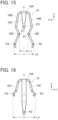
- smart clothes that can obtain user's biological data such as the heart rate and the body temperature only by being worn by the user.
- Such smart clothes have an electrode disposed at a measurement site, and when a wearable device serving as a measurement device is electrically connected to the electrode, biological data can be transmitted to the wearable device.
- the electrode and the wearable device can be interconnected by, for instance, use of a connector connected to a flexible conductor drawn from the electrode.
- JP 2018-129244 A discloses a connector as illustrated in FIG. 33 .
- the connector includes a housing 2 and a base member 3 that are disposed on the opposite sides of a flexible substrate 1 to sandwich the flexible substrate 1 therebetween.
- Tubular portions 4A of contacts 4 are passed through contact through-holes 2A of the housing 2, and flanges 4B of the contacts 4 are sandwiched between the housing 2 and flexible conductors 1A exposed on the top surface of the flexible substrate 1.
- housing fixing posts 3B formed to project from the base member 3 are press-fitted into post accommodating portions 2B of the housing 2 as shown in FIG. 33 , so that the housing 2 and the base member 3 are fixed to each other.
- a wearable device When fitted to the connector disclosed in JP 2018-129244 A , a wearable device can be connected to electrodes constituted of the flexible conductors.
- a connector including a pushing member having a projection, a support member disposed to contact a lateral surface of the projection, and a contact made of a conductive material and having a support member facing portion facing the support member, a part of the flexible conductor being disposed between the support member and the support member facing portion of the contact, the lateral surface of the projection pressing the part of the flexible conductor against the support member facing portion of the contact via the support member, whereby the contact is electrically connected to the flexible conductor.
- the present invention has been made to solve the foregoing problem and aims at providing a connector that can electrically connecting a contact to a flexible conductor of a connection object regardless of whether the flexible conductor is exposed on the top surface or the bottom surface of the connection object.
- a connector according to the present invention comprises:
- a connecting method according to the present invention is a method for connecting the plug contact to the flexible conductor of the connection object by use of the connector according to claim 1, the method comprising:
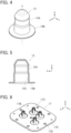
- FIG. 1 shows a connector 11 according to Embodiment 1.
- the connector 11 is used as, for instance, a garment-side connector for fitting a wearable device and includes a housing 12 made of an insulating material.
- Four plug contacts 13 are retained in the housing 12, and a reinforcement sheet 14 and a sheet type conductive member 15 being superposed on each other are retained by the housing 12.
- the sheet type conductive member 15 constitutes a connection object to which the connector 11 is connected.
- the four plug contacts 13 are aligned in two rows parallel to each other and disposed to project perpendicularly to the sheet type conductive member 15.
- the reinforcement sheet 14 and the sheet type conductive member 15 are defined as extending in an XY plane, the alignment direction of the four plug contacts 13 is referred to as "Y direction,” and the direction in which the four plug contacts 13 project is referred to as "+Z direction.”
- the Z direction is a fitting direction in which the connector 11 is fitted to a counter connector.
- FIG. 2 shows an assembly view of the connector 11.
- the connector 11 includes a top insulator 16 and a bottom insulator 17, and these top and bottom insulators 16 and 17 constitute the housing 12.
- the four plug contacts 13 are retained in the top insulator 16.
- the reinforcement sheet 14 is disposed on the bottom surface of the top insulator 16 on the -Z direction side, and the sheet type conductive member 15 is disposed on the -Z direction side of the reinforcement sheet 14.
- four inner contacts 18 are disposed on the -Z direction side of the sheet type conductive member 15, and the bottom insulator 17 is disposed on the -Z direction side of the inner contacts 18.
- the four inner contacts 18 separately correspond to the four plug contacts 13.
- the top insulator 16 includes a recessed portion 16A opening in the +Z direction and four contact through-holes 16B formed within the recessed portion 16A.
- the recessed portion 16A constitutes a counter connector accommodating portion in which a part of a counter connector (not shown) is to be accommodated, and the four contact through-holes 16B correspond to the four plug contacts 13.
- a plurality of bosses 16C projecting in the -Z direction are formed on a surface, facing the -Z direction, of the top insulator 16.
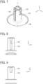
- the four plug contacts 13 are made of a conductive material such as metal and are to be connected to corresponding contacts of a counter connector (not shown) when a part of the counter connector is accommodated in the recessed portion 16A of the top insulator 16.
- the plug contact 13 includes a protrusion portion protruding in the +Z direction along a fitting axis C, specifically, a tubular portion 13A in the shape of a cylindrical tube, and a flange 13B in a discoid shape extending in a radial direction along an XY plane from the -Z directional base end of the tubular portion 13A.
- the interior of the tubular portion 13A forms a recessed portion 13C opening in the -Z direction.
- the fitting axis C is an axis passing through the center of the tubular portion 13A and extending in the direction in which the connector 11 and a counter connector are fitted to each other.
- tubular portion 13A has the shape of a cylindrical tube, the cross section thereof is not limited to a circle and may be any of various shapes such as an ellipse and a polygon as long as the tubular portion 13A has the recessed portion 13C in its interior.
- the four plug contacts 13 can be each used as a terminal for transmitting electric signals.
- the bottom insulator 17 includes a flat plate portion 17A, and the flat plate portion 17A is provided with four circular recessed portions 17B opening in the +Z direction.
- the four recessed portions 17B correspond to the four plug contacts 13.
- the four recessed portions 17B are provided separately with four projections 17C projecting in the +Z direction from central parts of the respective recessed portions 17B.
- the flat plate portion 17A is provided with a plurality of through-holes 17D corresponding to the bosses 16C of the top insulator 16.
- the projection 17C formed in the recessed portion 17B of the bottom insulator 17 has the shape of a circular column extending in the Z direction along the fitting axis C of the plug contact 13 situated to correspond to the recessed portion 17B.
- First arm insertion grooves 17E extending in the Z direction are formed at the lateral surface of the projection 17C separately on the opposite sides in the X direction
- second arm insertion grooves 17F extending in the Z direction are formed at the lateral surface of the projection 17C separately on the opposite sides in the Y direction.
- a part facing the +X direction and a part facing the -X direction are each provided with the first arm insertion groove 17E, and a part facing the +Y direction and a part facing the -Y direction are each provided with the second arm insertion groove 17F.
- the first arm insertion groove 17E extends over the entire Z directional height of the projection 17C from the +Z directional end of the projection 17C to the -Z directional end thereof, and as shown in FIG. 9 , the second arm insertion groove 17F extends from the +Z directional end of the projection 17C to an intermediate portion thereof in the Z direction.
- each first arm insertion groove 17E includes: a first bottom surface 17G extending along a YZ plane in a portion on the +Z direction side; a second bottom surface 17H extending along a YZ plane in a portion on the -Z direction side and situated away from the fitting axis C in the X direction compared to the first bottom surface 17G; and an inclined bottom surface 17J connecting the first bottom surface 17G and the second bottom surface 17H and inclined with respect to the fitting axis C.
- the projection 17C has a thickness D1 in the X direction at a Z directional position where the first bottom surface 17G is formed and, at a Z directional position where the second bottom surface 17H is formed, a thickness D2 in the X direction that is larger than the thickness D1 at the Z directional position of the first bottom surface 17G.
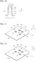
- the sheet type conductive member 15 has a multilayer structure in which a plurality of wiring layers each formed of a flexible conductor and a plurality of insulating layers are laminated.
- each of the four contact arrangement regions 15A is provided with an opening 15B penetrating the sheet type conductive member 15 and further with a pair of substantially triangular protruding portions 15C protruding inward within the opening 15B separately from the +X directional edge and the -X directional edge of the contact arrangement region 15A.
- a wiring layer 15D is exposed on the protruding portions 15C protruding inward within the four openings 15B, while an insulating layer 15E is exposed in the other region than the four openings 15B.
- a wiring layer 15F is exposed on the protruding portions 15C protruding inward within the four openings 15B, while an insulating layer 15G is exposed in the other region than the four openings 15B.
- the sheet type conductive member 15 is provided in its peripheral portion with a plurality of through-holes 15H corresponding to the bosses 16C of the top insulator 16 as shown in FIGS. 11 and 12 .
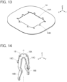
- the reinforcement sheet 14 is used to reinforce a mounting object (not shown) such as a garment on which the connector 11 is to be mounted.
- the reinforcement sheet 14 is made of an insulating material and provided at its center with an opening 14A. Further, a plurality of notches 14B corresponding to the bosses 16C of the top insulator 16 are formed along the periphery of the opening 14A of the reinforcement sheet 14.
- FIG. 14 shows the structure of an inner contact 18.
- the inner contact 18 is formed of a plate member made of a conductive material such as metal and bent, and includes a base portion 18A situated on the fitting axis C and extending in an XY plane, a pair of first arm portions 18B extending in at least the -Z direction separately from the +X directional end and the -X directional end of the base portion 18A, and a pair of second arm portions 18C extending in at least the -Z direction separately from the +Y directional end and the -Y directional end of the base portion 18A.
- the X direction forms a first direction perpendicular to the fitting axis C
- the Y direction forms a second direction perpendicular to the fitting axis C and also perpendicular to the first direction.
- the pair of first arm portions 18B face each other in the X direction and have a symmetrical shape with respect to a YZ plane passing the fitting axis C.
- the pair of first arm portions 18B have, in their intermediate portions in the Z direction, a pair of first bending portions 18D bent to approach each other and each form a projecting shape, and projecting surfaces of the pair of first bending portions 18D that face each other form a pair of projection contacting portions P1 that are elastically displaceable in the X direction perpendicular to the fitting axis C.
- the pair of first arm portions 18B also have, in their -Z directional tip portions, a pair of projecting surfaces facing the opposite directions from each other in the X direction, and this pair of projecting surfaces form a pair of pressing portions P2 that are elastically displaceable in the X direction perpendicular to the fitting axis C.
- a distance L1 between the pair of projection contacting portions P1 in the X direction has a dimension substantially equal to the thickness D1 of the projection 17C of the bottom insulator 17 shown in FIG. 10 and smaller than the thickness D2 thereof, and a distance L2 between the pair of pressing portions P2 in the X direction has a dimension substantially equal to or slightly smaller than a value obtained by subtracting a double of the thickness of the sheet type conductive member 15 from the inner diameter of the recessed portion 13C of the plug contact 13.
- the pair of second arm portions 18C slantingly extend from the +Y and -Y directional ends of the base portion 18A such that a gap therebetween in the Y direction gradually widens toward the -Z direction, face each other in the Y direction, and have a symmetrical shape with respect to an XZ plane passing the fitting axis C.
- the -Z directional tip portions of the pair of second arm portions 18C have a pair of projecting surfaces facing the opposite directions from each other in the Y direction, and this pair of projecting surfaces form a pair of contact portions P3 that are elastically displaceable in the Y direction perpendicular to the fitting axis C.
- a distance L3 between the pair of contact portions P3 in the Y direction has a dimension larger than the inner diameter of the recessed portion 13C of the plug contact 13.
- each inner contact 18 is temporarily retained on the corresponding projection 17C of the bottom insulator 17 as shown in FIG. 17 .
- the inner contact 18 is temporarily retained on the projection 17C with the pair of first arm portions 18B being inserted in the pair of first arm insertion grooves 17E of the projection 17C and the pair of projection contacting portions P1 being in contact with the first bottom surfaces 17G of the first arm insertion grooves 17E shown in FIG. 10 .
- the bosses 16C of the top insulator 16 are inserted into the notches 14B of the reinforcement sheet 14.
- the four contact through-holes 16B of the top insulator 16 are situated inside the opening 14A of the reinforcement sheet 14.
- tubular portions 13A of the plug contacts 13 are correspondingly inserted into the four contact through-holes 16B of the top insulator 16 from the -Z direction, and the sheet type conductive member 15 is disposed on the -Z direction side of the four plug contacts 13 such that each opening 15B and each pair of protruding portions 15C of the sheet type conductive member 15 are positioned at an opening end portion of the recessed portion 13C of the corresponding tubular portion 13A.
- the pair of protruding portions 15C of the sheet type conductive member 15 pushed into the recessed portion 13C of the plug contact 13 are sandwiched between the pair of pressing portions P2 formed at the -Z directional end portions of the pair of first arm portions 18B of the inner contact 18 and the inner surface of the recessed portion 13C of the plug contact 13.
- the pair of pressing portions P2 have the distance L2 in the X direction that is substantially equal to or slightly smaller than a value obtained by subtracting a double of the thickness of the sheet type conductive member 15 from the inner diameter of the recessed portion 13C of the plug contact 13 as shown in FIG. 15 ; therefore, the pair of protruding portions 15C of the sheet type conductive member 15 are smoothly inserted into the recessed portion 13C of the plug contact 13 without being subjected to a large force from the inner contact 18 and being rubbed.
- the pair of projection contacting portions P1 of the inner contact 18 are in contact with the first bottom surfaces 17G of the pair of first arm insertion grooves 17E of the projection 17C, and when the bottom insulator 17 is pushed toward the top insulator 16 in the +Z direction, the base portion 18A of the inner contact 18 makes contact with the bottom surface of the recessed portion 13C of the plug contact 13, the bottom surface being situated at the +Z directional end of the recessed portion 13C.
- the pair of projection contacting portions P1 of the inner contact 18 are relatively moved in the -Z direction with respect to the projection 17C from the first bottom surfaces 17G of the pair of first arm insertion grooves 17E to the second bottom surfaces 17H thereof through the inclined bottom surfaces 17J thereof while being elastically displaced in the X direction.
- the bosses 16C of the top insulator 16 sequentially pass through the notches 14B of the reinforcement sheet 14, the through-holes 15H of the sheet type conductive member 15, and the through-holes 17D of the bottom insulator 17. Then, the ends of the bosses 16C projecting on the -Z direction side of the bottom insulator 17 are thermally deformed, whereby the top insulator 16 and the bottom insulator 17 are fixed to each other. Thus, the assembling operation of the connector 11 is completed.
- plug contacts 13 are fixed to the top insulator 16 and the bottom insulator 17 because their flanges 13B are sandwiched between the top insulator 16 and the bottom insulator 17.
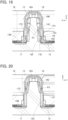
- the pair of projection contacting portions P1 of the inner contact 18 make contact with the second bottom surfaces 17H of the pair of first arm insertion grooves 17E of the projection 17C as shown in FIG. 19 , so that the distance between the pair of projection contacting portions P1 in the X direction is widened, and accordingly, elastic forces acting to widen the distance between the pair of pressing portions P2 in the X direction are exerted on the pair of pressing portions P2. Consequently, the pair of protruding portions 15C of the sheet type conductive member 15 sandwiched between the pair of pressing portions P2 of the inner contact 18 and the inner surface of the recessed portion 13C of the plug contact 13 are separately pressed against the inner surface of the recessed portion 13C of the plug contact 13.
- the wiring layer 15D is exposed on the top surfaces, facing the +Z direction, of the pair of protruding portions 15C, and the wiring layer 15F is exposed on the bottom surfaces thereof facing the -Z direction, as shown in FIGS. 11 and 12 .
- the wiring layer 15D on the top surfaces of the protruding portions 15C make contact with the inner surface of the recessed portion 13C of the plug contact 13 at a predetermined contact pressure, while the wiring layer 15F on the bottom surfaces of the protruding portions 15C make contact with the pressing portions P2 of the inner contact 18 at a predetermined contact pressure.
- the pair of contact portions P3 formed at the tip portions of the pair of second arm portions 18B of the inner contact 18 inserted in the recessed portion 13C of the plug contact 13 are pressed against the inner surface of the recessed portion 13C of the plug contact 13, whereby the inner contact 18 is electrically connected to the plug contact 13.
- the wiring layer 15D exposed on the top surfaces of the protruding portions 15C of the sheet type conductive member 15 are electrically connected to the plug contact 13 directly, while the wiring layer 15F exposed on the bottom surfaces of the protruding portions 15C of the sheet type conductive member 15 are electrically connected to the plug contact 13 via the inner contact 18.
- both the wiring layers 15D and 15F are connected to the plug contact 13.
- both the wiring layer 15D formed of a flexible conductor disposed on the top surface side of the sheet type conductive member 15 and the wiring layer 15F formed of a flexible conductor disposed on the bottom surface side of the same can be electrically connected to one plug contact 13 owing to the use of the inner contact 18.
- the plug contact 13 can be electrically connected to the flexible conductor on the top surface side of the sheet type conductive member, and when the connector 11 is connected to a sheet type conductive member having a flexible conductor exposed only on the bottom surface side, the plug contact 13 can be electrically connected to the flexible conductor on the bottom surface side of the sheet type conductive member.
- the plug contact 13 can be electrically connected to both the flexible conductor on the top surface side of the sheet type conductive member and the flexible conductor on the bottom surface side thereof.
- the pair of protruding portions 15C of the sheet type conductive member 15 are not subjected to a large force from the inner contact 18 and not rubbed when inserted into the recessed portion 13C of the plug contact 13, and hence, the flexible conductors forming the wiring layers 15D and 15F of the sheet type conductive member 15 are prevented from being broken, thus ensuring the reliability of electric connection between the flexible conductors and the plug contact 13.
- the reinforcement sheet 14 is disposed between the bottom insulator 17 and the top insulator 16 in the connector 11 of Embodiment 1, the reinforcement sheet 14 may be omitted when it is not necessary to reinforce the mounting object such as a garment on which the connector 11 is to be mounted.
- FIG. 21 shows an assembly view of a connector 21 according to Embodiment 2.
- the connector 21 is configured by, in the connector 11 of Embodiment 1, using a bottom insulator 27 in place of the bottom insulator 17 so that the top insulator 16 and the bottom insulator 27 constitute a housing 22 and also using four inner contacts 28 in place of the four inner contacts 18.
- the configuration other than the above is the same as that of the connector 11 of Embodiment 1.
- the four plug contacts 13 are retained in the top insulator 16, the reinforcement sheet 14 is disposed on the bottom surface of the top insulator 16 on the - Z direction side, and the sheet type conductive member 15 is disposed on the -Z direction side of the reinforcement sheet 14. Further, the four inner contacts 28 are disposed on the -Z direction side of the sheet type conductive member 15, and the bottom insulator 27 is disposed on the -Z direction side of the inner contacts 28.
- the bottom insulator 27 is configured such that four projections 27C are used in place of the four projections 17C in the bottom insulator 17 used in the connector 11 of Embodiment 1.
- the bottom insulator 27 includes the flat plate portion 17A, the flat plate portion 17A is provided with the four circular recessed portions 17B opening in the +Z direction, and the four projections 27C are formed to project in the +Z direction from central parts of the respective recessed portions 17B.
- the projection 27C of the bottom insulator 27 has the shape of a circular column extending in the Z direction along the fitting axis C of the plug contact 13 situated to correspond to the recessed portion 17B.
- the first arm insertion grooves 17E extending in the Z direction are formed at the lateral surface of the projection 27C separately on the opposite sides in the X direction.
- Those first arm insertion grooves 17E are the same as the first arm insertion grooves 17E of the projection 17C in Embodiment 1.
- No grooves are formed at the lateral surface of the projection 27C on the opposite sides in the Y direction.
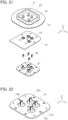
- FIG. 24 shows the structure of the inner contact 28.
- the inner contact 28 is formed of a plate member made of a conductive material such as metal and bent, and includes a base portion 28A situated on the fitting axis C and extending in an XY plane, and a pair of first arm portions 28B extending in the -Z direction separately from the +X directional end and the -X directional end of the base portion 28A.
- the pair of first arm portions 28B face each other in the X direction and have a symmetrical shape with respect to a YZ plane passing the fitting axis C.
- the pair of first arm portions 28B have a pair of projection contacting portions P1 that are formed in the intermediate portions in the Z direction and are elastically displaceable in the X direction and a pair of pressing portions P2 that are formed in the - Z directional tip portions and are elastically displaceable in the X direction, as with the pair of first arm portions 18B of the inner contact 18 in Embodiment 1.
- the pair of first arm portions 28B further have a pair of second bending portions 28E bent to project in the opposite directions from each other along the X direction, each second bending portion 28E being situated between a joint portion at which the first arm portion 28B and the base portion 28A are joined together and the projection contacting portion P1. Projecting surfaces of the pair of second bending portions 28E that face the opposite directions from each other form a pair of contact portions P3 elastically displaceable in the X direction perpendicular to the fitting axis C.
- a distance L4 between the pair of contact portions P3 in the X direction has a dimension substantially equal to or slightly smaller than the inner diameter of the recessed portion 13C of the plug contact 13.
- each inner contact 28 is temporarily retained on the corresponding projection 27C of the bottom insulator 27.
- the inner contact 28 is temporarily retained on the projection 27C with the pair of first arm portions 28B being inserted in the pair of first arm insertion grooves 17E of the projection 27C.
- the bosses 16C of the top insulator 16 are inserted into the notches 14B of the reinforcement sheet 14. Further, the tubular portions 13A of the plug contacts 13 are correspondingly inserted into the four contact through-holes 16B of the top insulator 16 from the -Z direction, and the sheet type conductive member 15 is disposed on the -Z direction side of the four plug contacts 13 such that each opening 15B and each pair of protruding portions 15C of the sheet type conductive member 15 are positioned at an opening end portion of the recessed portion 13C of the corresponding tubular portion 13A.
- the bottom insulator 27 is pushed toward the top insulator 16 in the +Z direction with the sheet type conductive member 15 being sandwiched therebetween.
- the flange 13B of each plug contact 13 is situated above the corresponding contact arrangement region 15A of the sheet type conductive member 15, and each inner contact 28 temporarily retained on the bottom insulator 27 is inserted into the recessed portion 13C of the corresponding plug contact 13 while pushing the corresponding pair of protruding portions 15C of the sheet type conductive member 15.
- the pair of protruding portions 15C of the sheet type conductive member 15 pushed into the recessed portion 13C of the plug contact 13 are sandwiched between the pair of pressing portions P2 formed at the -Z directional end portions of the pair of first arm portions 28B of the inner contact 28 and the inner surface of the recessed portion 13C of the plug contact 13.
- the pair of pressing portions P2 have a distance therebetween in the X direction that is substantially equal to or slightly smaller than a value obtained by subtracting a double of the thickness of the sheet type conductive member 15 from the inner diameter of the recessed portion 13C of the plug contact 13 as with Embodiment 1; therefore, the pair of protruding portions 15C of the sheet type conductive member 15 are smoothly inserted into the recessed portion 13C of the plug contact 13 without being subjected to a large force from the inner contact 28 and being rubbed.
- the pair of projection contacting portions P1 of the inner contact 28 are in contact with the first bottom surfaces 17G of the pair of first arm insertion grooves 17E of the projection 27C, and when the bottom insulator 27 is pushed toward the top insulator 16 in the +Z direction, the base portion 28A of the inner contact 28 makes contact with the bottom surface, situated at the +Z directional end, of the recessed portion 13C of the plug contact 13.
- the pair of projection contacting portions P1 of the inner contact 28 are relatively moved in the -Z direction with respect to the projection 27C from the first bottom surfaces 17G of the pair of first arm insertion grooves 17E to the second bottom surfaces 17H thereof through the inclined bottom surfaces 17J thereof while being elastically displaced in the X direction.
- the bosses 16C of the top insulator 16 sequentially pass through the notches 14B of the reinforcement sheet 14, the through-holes 15H of the sheet type conductive member 15, and the through-holes 17D of the bottom insulator 27. Then, the ends of the bosses 16C projecting on the -Z direction side of the bottom insulator 27 are thermally deformed, whereby the top insulator 16 and the bottom insulator 27 are fixed to each other. Thus, the assembling operation of the connector 11 is completed.
- the pair of projection contacting portions P1 of the inner contact 28 make contact with the second bottom surfaces 17H of the pair of first arm insertion grooves 17E of the projection 27C as shown in FIG. 27 , so that the distance between the pair of projection contacting portions P1 in the X direction is widened, and accordingly, elastic forces act on the pair of pressing portions P2 to widen the distance between the pair of pressing portions P2 in the X direction. Consequently, the pair of protruding portions 15C of the sheet type conductive member 15 sandwiched between the pair of pressing portions P2 of the inner contact 28 and the inner surface of the recessed portion 13C of the plug contact 13 are separately pressed against the inner surface of the recessed portion 13C of the plug contact 13.
- the wiring layer 15D on the top surfaces of the protruding portions 15C makes contact with the inner surface of the recessed portion 13C of the plug contact 13 at a predetermined contact pressure
- the wiring layer 15F on the bottom surfaces of the protruding portions 15C makes contact with the pressing portions P2 of the inner contact 28 at a predetermined contact pressure
- the wiring layer 15D exposed on the top surfaces of the protruding portions 15C of the sheet type conductive member 15 are electrically connected to the plug contact 13 directly, while the wiring layer 15F exposed on the bottom surfaces of the protruding portions 15C of the sheet type conductive member 15 are electrically connected to the plug contact 13 via the inner contact 28.
- both the wiring layers 15D and 15F are connected to the plug contact 13.
- both the wiring layer 15D formed of a flexible conductor disposed on the top surface side of the sheet type conductive member 15 and the wiring layer 15F formed of a flexible conductor disposed on the bottom surface side of the same can be electrically connected to one plug contact 13 owing to the use of the inner contact 28.
- the plug contact 13 can be electrically connected to the flexible conductor on the top surface side of the sheet type conductive member, and when the connector 21 is connected to a sheet type conductive member having a flexible conductor exposed only on the bottom surface side, the plug contact 13 can be electrically connected to the flexible conductor on the bottom surface side of the sheet type conductive member, as with Embodiment 1.
- the pair of protruding portions 15C of the sheet type conductive member 15 are not subjected to a large force from the inner contact 28 and not rubbed when inserted into the recessed portion 13C of the plug contact 13, and hence, the flexible conductors forming the wiring layers 15D and 15F of the sheet type conductive member 15 are prevented from being broken, thus ensuring the reliability of electric connection between the flexible conductors and the plug contact 13.
- FIG. 28 shows a connector 31 according to Embodiment 3.
- the connector 31 is configured by, in the connector 21 of Embodiment 2, using a top insulator 36 in place of the top insulator 16 so that the top insulator 36 and the bottom insulator 27 constitute a housing 32 and also using four plug contacts 33 in place of the four plug contacts 13.
- the configuration other than the above is the same as that of the connector 21 of Embodiment 2.
- the four plug contacts 33 are retained in the top insulator 36.
- the top insulator 36 includes a recessed portion 36A opening in the +Z direction as with the top insulator 16 shown in FIG. 3 .
- Two jutting portions 36D and 36E jutting in the +Z direction are formed within the recessed portion 36A.
- the jutting portions 36D and 36E are situated at a distance in the X direction and each extend in the Y direction.
- Each of the jutting portions 36D and 36E is provided with two contact through-holes 36B penetrating the top insulator 36 in the Z direction, and the corresponding plug contacts 33 are exposed toward the +Z direction through the contact through-holes 36B.
- bosses 16C projecting in the -Z direction are formed on a surface, facing the -Z direction, of the top insulator 36, as with the top insulator 16 shown in FIG. 3 .
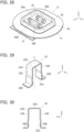
- the structure of the plug contact 33 is shown in FIGS. 29 and 30 .
- the plug contact 33 is formed from a bent metal plate and includes a protrusion portion formed of a U-shaped portion 33A protruding in the +Z direction along the fitting axis C.
- the U-shaped portion 33A is composed of a top plate portion 33D extending along an XY plane and a pair of lateral plate portions 33E extending in the -Z direction along a YZ plane separately from the +X directional end and the -X directional end of the top plate portion 33D.
- the plug contact 33 further includes a pair of flanges 33B of flat plate shape extending in the opposite directions from each other along an XY plane separately from the -Z directional ends of the pair of lateral plate portions 33E.
- the interior of the U-shaped portion 33A forms a recessed portion 33C.
- the connector 31 can be assembled in the same manner as in Embodiment 2.
- the inner contacts 28 as shown in FIGS. 24 and 25 are temporarily retained on the corresponding projections 27C of the bottom insulator 27, the U-shaped portions 33A of the plug contacts 33 are correspondingly inserted into the four contact through-holes 36B of the top insulator 36 from the -Z direction, and the sheet type conductive member 15 is disposed on the -Z direction side of the four plug contacts 33 such that each opening 15B and each pair of protruding portions 15C of the sheet type conductive member 15 are positioned at an opening end portion of the recessed portion 33C of the corresponding U-shaped portion 33A.
- each inner contact 28 temporarily retained on the bottom insulator 27 is inserted into the recessed portion 33C of the corresponding plug contact 33 while pushing the corresponding pair of protruding portions 15C of the sheet type conductive member 15.
- the pair of protruding portions 15C of the sheet type conductive member 15 pushed into the recessed portion 33C of the plug contact 33 are sandwiched between the pair of pressing portions P2 of the inner contact 28 and the inner surface of the recessed portion 33C of the plug contact 33.
- the distance between the pair of contact portions P3 in the X direction has a dimension substantially equal to or slightly smaller than a distance between the inner surfaces of the recessed portion 33C of the plug contact 33 in the X direction.
- the pair of protruding portions 15C of the sheet type conductive member 15 are smoothly inserted into the recessed portion 33C of the plug contact 33 without being subjected to a large force from the inner contact 28 and being rubbed.
- the pair of projection contacting portions P1 of the inner contact 28 are relatively moved in the -Z direction with respect to the projection 27C from the first bottom surfaces 17G of the pair of first arm insertion grooves 17E of the projection 27C to the second bottom surfaces 17H thereof through the inclined bottom surfaces 17J thereof while being elastically displaced in the X direction.
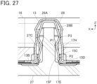
- the pair of projection contacting portions P1 of the inner contact 28 make contact with the second bottom surfaces 17H of the pair of first arm insertion grooves 17E of the projection 27C as shown in FIG. 32 , so that the distance between the pair of projection contacting portions P1 in the X direction is widened. Accordingly, elastic forces acting to widen the distance between the pair of pressing portions P2 in the X direction are exerted on the pair of pressing portions P2, and the pair of protruding portions 15C of the sheet type conductive member 15 are separately pressed against the inner surface of the recessed portion 33C of the plug contact 33.
- the wiring layer 15D on the top surfaces of the protruding portions 15C makes contact with the inner surface of the recessed portion 33C of the plug contact 33 at a predetermined contact pressure
- the wiring layer 15F on the bottom surfaces of the protruding portions 15C makes contact with the pressing portions P2 of the inner contact 28 at a predetermined contact pressure
- the pair of contact portions P3 of the inner contact 28 are pressed against the inner surface of the recessed portion 33C of the plug contact 33, whereby the inner contact 28 is electrically connected to the plug contact 33.
- both the wiring layer 15D formed of a flexible conductor disposed on the top surface side of the sheet type conductive member 15 and the wiring layer 15F formed of a flexible conductor disposed on the bottom surface side of the same can be electrically connected to one plug contact 33.
- the plug contact 33 can be electrically connected to the flexible conductor on the top surface side of the sheet type conductive member, and when the connector 31 is connected to a sheet type conductive member having a flexible conductor exposed only on the bottom surface side, the plug contact 33 can be electrically connected to the flexible conductor on the bottom surface side of the sheet type conductive member, as with Embodiments 1 and 2.
- the pair of protruding portions 15C of the sheet type conductive member 15 are not subjected to a large force from the inner contact 28 and not rubbed when inserted into the recessed portion 33C of the plug contact 33, and hence, the flexible conductors forming the wiring layers 15D and 15F of the sheet type conductive member 15 are prevented from being broken, thus ensuring the reliability of electric connection between the flexible conductors and the plug contact 33.
- the plug contact 13, 33 disposed in the contact arrangement region 15A of the sheet type conductive member 15 makes contact with both the wiring layer 15D exposed on the top surface side of the sheet type conductive member 15 and the wiring layer 15F exposed on the bottom surface side of the sheet type conductive member 15; however, for instance, it is also possible to connect only the wiring layer 15D exposed on the bottom surface side of the sheet type conductive member 15 to the plug contact 13, 33 disposed in the contact arrangement region 15A.
- the sheet type conductive member 15 used in Embodiments 1 to 3 above has a multilayer structure, the invention is not limited thereto, and it is sufficient that a conductive member has a flexible conductor exposed on at least one surface of the conductive member.
- the invention is not limited thereto, and three or more layers of flexible conductors can be connected to one plug contact 13, 33.
- the connector 11, 21, 31 according to Embodiments 1 to 3 above has four plug contacts 13, 33
- the number of the plug contacts 13, 33 is not limited, and it is sufficient that there is provided one plug contact 13, 33 electrically connected to a flexible conductor exposed on at least one surface of the sheet type conductive member 15.
Landscapes
- Engineering & Computer Science (AREA)
- Manufacturing & Machinery (AREA)
- Coupling Device And Connection With Printed Circuit (AREA)
Claims (14)
- Verbinder, umfassend:einen Steckkontakt (13, 33), der eine leitende Eigenschaft besitzt und einen ausgesparten Abschnitt (13C, 33C) aufweist, der sich entlang einer Montageachse (C) erstreckt;einen inneren Kontakt (18, 28), der eine leitende Eigenschaft besitzt und in den ausgesparten Abschnitt eingesetzt ist; undeinen unteren Isolator (17, 27), der einen Vorsprung (17C, 27C) aufweist, der sich entlang der Montageachse erstreckt und in den ausgesparten Abschnitt eingesetzt ist,wobei der innere Kontakt (18, 28) aufweist:einen Kontaktabschnitt (P3), der in einer Richtung senkrecht zu der Montageachse elastisch verschiebbar ist und mit dem Steckkontakt in dem ausgesparten Abschnitt Kontakt herstellt,einen Vorsprungkontaktierungsabschnitt (P1), der in einer Richtung senkrecht zu der Montageachse elastisch verschiebbar ist und mit einer Seitenfläche des Vorsprungs in dem ausgesparten Abschnitt Kontakt herstellt, undeinen Drückabschnitt (P2), der in einer Richtung senkrecht zu der Montageachse elastisch verschiebbar ist und einer Innenfläche des ausgesparten Abschnitts zugewandt ist, und ein Teil eines Verbindungsobjekts (15) vom Flachmaterialtyp, der einen flexiblen Leiter (15D, 15F) aufweist, der an mindestens einer Fläche des Verbindungsobjekts frei liegt, zwischen dem Drückabschnitt und einer Innenfläche des ausgesparten Abschnitts in einer Richtung senkrecht zu der Montageachse aufgenommen ist, die Innenfläche des ausgesparten Abschnitts Kontakt mit einer Oberseite des Verbindungsobjekts herstellt, und der Drückabschnitt Kontakt mit einer Unterseite des Verbindungsobjekts herstellt, wodurch der Steckkontakt (13, 33) direkt elektrisch mit dem flexiblen Leiter (15D) verbunden ist, wenn der flexible Leiter (15D) an der Oberseite des Verbindungsobjekts frei liegt, und der Steckkontakt (13, 33) über den inneren Kontakt (18, 28) elektrisch mit dem flexiblen Leiter (15F) verbunden ist, wenn der flexible Leiter (15F) an der Unterseite des Verbindungsobjekts frei liegt.
- Verbinder nach Anspruch 1,wobei der innere Kontakt (18, 28) aufweist: einen Basisabschnitt (18A, 28A), der einer Unterseite des ausgesparten Abschnitts innerhalb des ausgesparten Abschnitts zugewandt ist; und ein Paar von ersten Armabschnitten (18B, 28B), die sich in einer Richtung entlang mindestens der Montageachse getrennt von gegenüberliegenden Enden des Basisabschnitts in einer ersten Richtung senkrecht zu der Montageachse erstrecken und einander in der ersten Richtung zugewandt sind, undder Vorsprungkontaktierungsabschnitt (P1) an jedem von Zwischenabschnitten des Paares von ersten Armabschnitten angeordnet ist und der Drückabschnitt (P2) an jedem von Spitzenabschnitten des Paares von ersten Armabschnitten angeordnet ist.
- Verbinder nach Anspruch 2,wobei die Zwischenabschnitte des Paares von ersten Armabschnitten (18B) ein Paar von ersten Biegeabschnitten (18D) aufweisen, die jeweils so gebogen sind, dass sie in der ersten Richtung vorstehen,jede der vorstehenden Flächen des Paares von ersten Biegeabschnitten, die einander zugewandt sind, den Vorsprungkontaktierungsabschnitt (P1) bildet, unddie Drückabschnitte (P2), die an den Spitzenabschnitten des Paares von ersten Armabschnitten angeordnet sind, entlang der ersten Richtung in voneinander entgegengesetzte Richtungen weisen.
- Verbinder nach Anspruch 2 oder 3,
wobei der innere Kontakt (18) ein Paar von zweiten Armabschnitten (18C) aufweist, die sich in einer Richtung entlang mindestens der Montageachse getrennt von gegenüberliegenden Enden des Basisabschnitts in einer zweiten Richtung senkrecht zu der Montageachse und außerdem senkrecht zu der ersten Richtung erstrecken und die einander in der zweiten Richtung zugewandt sind, und der Kontaktabschnitt (P3) an jedem von Spitzenabschnitten des Paares von zweiten Armabschnitten angeordnet ist. - Verbinder nach Anspruch 4,
wobei die Kontaktabschnitte (P3), die an den Spitzenabschnitten des Paares von zweiten Armabschnitten (18C) angeordnet sind, entlang der zweiten Richtung in voneinander entgegengesetzte Richtungen weisen. - Verbinder nach Anspruch 2,
wobei der Kontaktabschnitt (P3) zwischen einem Verbindungsabschnitt, an dem jeder des Paares von ersten Armabschnitten (28B) und der Basisabschnitt (28A) miteinander verbunden sind, und einem zugehörigen der Zwischenabschnitte angeordnet ist. - Verbinder nach Anspruch 6,wobei das Paar von ersten Armabschnitten (28B) ein Paar von zweiten Biegeabschnitten (28E) umfasst, die sich jeweils zwischen dem Verbindungsabschnitt, an dem jeder des Paares von ersten Armabschnitten und der Basisabschnitt (28A) miteinander verbunden sind, und einem zugehörigen der Zwischenabschnitte befinden und die so gebogen sind, dass sie entlang der ersten Richtung in voneinander entgegengesetzte Richtungen vorstehen, undjede der vorstehenden Flächen des Paares von zweiten Biegeabschnitten, die in voneinander entgegengesetzte Richtungen weisen, den Kontaktabschnitt (P3) bildet.
- Verbinder nach einem der Ansprüche 2-7,wobei der Vorsprung (17C, 27C) ein Paar von ersten Armeinführnuten (17E) aufweist, die sich entlang der Montageachse an der Seitenfläche des Vorsprungs an gegenüberliegenden Seiten in der ersten Richtung erstrecken und in die das Paar von ersten Armabschnitten (18B, 28B) eingeführt ist, undwenn die Vorsprungkontaktierungsabschnitte (P1) des Paares von ersten Armabschnitten Kontakt mit Unterseiten des Paares von ersten Armeinführnuten herstellen, die mit den Vorsprungkontaktierungsabschnitten verbundenen Drückabschnitte (P2) gegen die Innenfläche des ausgesparten Abschnitts (13C, 33C) gedrückt werden.
- Verbinder nach Anspruch 4 oder 5,
wobei der Vorsprung (17C) ein Paar von zweiten Armeinführnuten (17F) aufweist, die sich entlang der Montageachse an der Seitenfläche des Vorsprungs auf gegenüberliegenden Seiten in der zweiten Richtung erstrecken und in die das Paar von zweiten Armabschnitten eingeführt ist. - Verbinder nach einem der Ansprüche 1-9,wobei der Steckkontakt (13, 33) aufweist: einen Vorsprungsabschnitt (13A, 33A), der entlang der Montageachse vorsteht; und einen Flansch (13B, 33B), der sich von einem Basisende des Vorsprungsabschnitts in einer Richtung senkrecht zu der Montageachse erstreckt, undder ausgesparte Abschnitt (13C, 33C) von einem Inneren des Vorsprungsabschnitts gebildet ist.
- Verbinder nach Anspruch 10,
wobei der Steckkontakt (13) aufweist: den Vorsprungsabschnitt, der von einem rohrförmigen Abschnitt (13A) gebildet ist; und den Flansch (13B) in einer Scheibenform, der sich in einer radialen Richtung von einem Außenumfang des Basisendes des rohrförmigen Abschnitts erstreckt. - Verbinder nach Anspruch 10,
wobei der Steckkontakt (33) aufweist: den Vorsprungsabschnitt, der von einem U-förmigen Abschnitt (33A) gebildet ist; und den Flansch (33B), der ein Paar von flachen Plattenflansche umfasst, die sich von entgegengesetzten Enden des U-förmigen Abschnitts in voneinander entgegengesetzte Richtungen erstrecken. - Verbinder nach einem der Ansprüche 10-12, der ein Gehäuse (12, 22, 32) umfasst, das eine isolierende Eigenschaft besitzt und dazu eingerichtet ist, das Verbindungsobjekt (15), den Steckkontakt (13, 33) und den inneren Kontakt (18, 28) zu halten,
wobei das Gehäuse aufweist:einen oberen Isolator (16, 36), mit einem Kontaktdurchgangsloch (16B, 36B) versehen ist, durch das der Vorsprungsabschnitt des Steckkontakts hindurchgeführt ist; und den unteren Isolator (17, 27), undder obere Isolator so an dem unteren Isolator befestigt ist, dass der Vorsprungsabschnitt des Steckkontakts durch das Kontaktdurchgangsloch hindurch führt und das Verbindungsobjekt und der Flansch zwischen dem oberen Isolator (16, 36) und dem unteren Isolator (17, 27) sandwichartig aufgenommen ist. - Verbindungsverfahren zum Verbinden des Steckkontakts (13, 33) mit dem flexiblen Leiter (15D, 15F) des Verbindungsobjekts (15) unter Verwendung des Verbinders (11, 21) nach einem der Ansprüche 1-13, wobei das Verfahren umfasst:Anordnen des Verbindungsobjekts (15) in Bezug auf den Steckkontakt (13, 33) so, dass der flexible Leiter, der an mindestens einer Fläche des Verbindungsobjekts frei liegt, an einem Öffnungsendabschnitt des ausgesparten Abschnitts des Steckkontakts positioniert ist;Einführen des inneren Kontakts in den ausgesparten Abschnitt, während das Verbindungsobjekt in den ausgesparten Abschnitt geschoben wird, dergestalt, dass der Kontaktabschnitt (P3) des inneren Kontakts (18, 28) Kontakt mit dem Steckkontakt innerhalb des ausgesparten Abschnitts (13C, 33C) herstellt und dass das Verbindungsobjekt (15) zwischen dem Drückabschnitt (P2) des inneren Kontakts und der Innenfläche des ausgesparten Abschnitts in einer Richtung senkrecht zu der Montageachse (C) aufgenommen ist; undEinführen des Vorsprungs des unteren Isolators in den ausgesparten Abschnitt so, dass die Seitenfläche des Vorsprungs Kontakt mit dem Vorsprungkontaktierungsabschnitt des inneren Kontakts herstellt, woraufhin die Innenfläche des ausgesparten Abschnitts Kontakt mit der Oberseite des Verbindungsobjekts herstellt und der Drückabschnitt Kontakt mit der Unterseite des Verbindungsobjekts herstellt, wodurch der Steckkontakt (13, 33) direkt mit dem flexiblen Leiter (15D) elektrisch verbunden ist, wenn der flexible Leiter (15D) an der Oberseite des Verbindungsobjekts frei liegt, und der Steckkontakt (13, 33) über den inneren Kontakt (18, 28) elektrisch mit dem flexiblen Leiter (15F) verbunden ist, wenn der flexible Leiter (15F) an der Unterseite des Verbindungsobjekts frei liegt.
Applications Claiming Priority (1)
| Application Number | Priority Date | Filing Date | Title |
|---|---|---|---|
| JP2022211261A JP2024094608A (ja) | 2022-12-28 | 2022-12-28 | コネクタおよび接続方法 |
Publications (2)
| Publication Number | Publication Date |
|---|---|
| EP4395079A1 EP4395079A1 (de) | 2024-07-03 |
| EP4395079B1 true EP4395079B1 (de) | 2025-04-16 |
Family
ID=88923299
Family Applications (1)
| Application Number | Title | Priority Date | Filing Date |
|---|---|---|---|
| EP23211457.9A Active EP4395079B1 (de) | 2022-12-28 | 2023-11-22 | Verbinder und verbindungsverfahren |
Country Status (4)
| Country | Link |
|---|---|
| US (1) | US20240222893A1 (de) |
| EP (1) | EP4395079B1 (de) |
| JP (1) | JP2024094608A (de) |
| CN (1) | CN118263710A (de) |
Families Citing this family (1)
| Publication number | Priority date | Publication date | Assignee | Title |
|---|---|---|---|---|
| JP2024034807A (ja) * | 2022-09-01 | 2024-03-13 | 日本航空電子工業株式会社 | コネクタ |
Family Cites Families (6)
| Publication number | Priority date | Publication date | Assignee | Title |
|---|---|---|---|---|
| JP6840559B2 (ja) | 2017-02-10 | 2021-03-10 | 日本航空電子工業株式会社 | コネクタ |
| JP7178956B2 (ja) * | 2019-05-17 | 2022-11-28 | 日本航空電子工業株式会社 | 接続方法、接続構造および接続端子組立体 |
| JP7232144B2 (ja) * | 2019-07-19 | 2023-03-02 | 日本航空電子工業株式会社 | コネクタ |
| US11258189B2 (en) * | 2019-10-03 | 2022-02-22 | Japan Aviation Electronics Industry, Limited | Connector and connecting method |
| JP7822290B2 (ja) * | 2022-09-28 | 2026-03-02 | 日本航空電子工業株式会社 | コネクタ |
| JP2024075983A (ja) * | 2022-11-24 | 2024-06-05 | 日本航空電子工業株式会社 | コネクタ組立体 |
-
2022
- 2022-12-28 JP JP2022211261A patent/JP2024094608A/ja active Pending
-
2023
- 2023-11-22 EP EP23211457.9A patent/EP4395079B1/de active Active
- 2023-11-22 CN CN202311566450.2A patent/CN118263710A/zh active Pending
- 2023-11-28 US US18/520,744 patent/US20240222893A1/en active Pending
Also Published As
| Publication number | Publication date |
|---|---|
| EP4395079A1 (de) | 2024-07-03 |
| US20240222893A1 (en) | 2024-07-04 |
| CN118263710A (zh) | 2024-06-28 |
| JP2024094608A (ja) | 2024-07-10 |
Similar Documents
| Publication | Publication Date | Title |
|---|---|---|
| CN110915068B (zh) | 连接器组件 | |
| EP4346017B1 (de) | Verbinder | |
| EP4329104B1 (de) | Verbinder | |
| US12424774B2 (en) | Connector | |
| EP4395079B1 (de) | Verbinder und verbindungsverfahren | |
| US12230907B2 (en) | Electrical connector for connecting an electric wire to a flat flexible conductor and an electrical connector assembly therefor | |
| EP4462605B1 (de) | Verbinder | |
| US12567691B2 (en) | Connector | |
| EP4611180A1 (de) | Verbinder | |
| EP4333216B1 (de) | Verbinder | |
| JP2024033809A (ja) | コネクタおよびコネクタ組立体 | |
| EP4507128B1 (de) | Verbinder und verbinderanordnung | |
| US12537336B2 (en) | Connector |
Legal Events
| Date | Code | Title | Description |
|---|---|---|---|
| PUAI | Public reference made under article 153(3) epc to a published international application that has entered the european phase |
Free format text: ORIGINAL CODE: 0009012 |
|
| STAA | Information on the status of an ep patent application or granted ep patent |
Free format text: STATUS: REQUEST FOR EXAMINATION WAS MADE |
|
| 17P | Request for examination filed |
Effective date: 20231122 |
|
| AK | Designated contracting states |
Kind code of ref document: A1 Designated state(s): AL AT BE BG CH CY CZ DE DK EE ES FI FR GB GR HR HU IE IS IT LI LT LU LV MC ME MK MT NL NO PL PT RO RS SE SI SK SM TR |
|
| RBV | Designated contracting states (corrected) |
Designated state(s): AL AT BE BG CH CY CZ DE DK EE ES FI FR GB GR HR HU IE IS IT LI LT LU LV MC ME MK MT NL NO PL PT RO RS SE SI SK SM TR |
|
| GRAP | Despatch of communication of intention to grant a patent |
Free format text: ORIGINAL CODE: EPIDOSNIGR1 |
|
| STAA | Information on the status of an ep patent application or granted ep patent |
Free format text: STATUS: GRANT OF PATENT IS INTENDED |
|
| INTG | Intention to grant announced |
Effective date: 20241205 |
|
| GRAS | Grant fee paid |
Free format text: ORIGINAL CODE: EPIDOSNIGR3 |
|
| GRAA | (expected) grant |
Free format text: ORIGINAL CODE: 0009210 |
|
| STAA | Information on the status of an ep patent application or granted ep patent |
Free format text: STATUS: THE PATENT HAS BEEN GRANTED |
|
| AK | Designated contracting states |
Kind code of ref document: B1 Designated state(s): AL AT BE BG CH CY CZ DE DK EE ES FI FR GB GR HR HU IE IS IT LI LT LU LV MC ME MK MT NL NO PL PT RO RS SE SI SK SM TR |
|
| REG | Reference to a national code |
Ref country code: GB Ref legal event code: FG4D |
|
| REG | Reference to a national code |
Ref country code: CH Ref legal event code: EP Ref country code: DE Ref legal event code: R096 Ref document number: 602023002963 Country of ref document: DE |
|
| REG | Reference to a national code |
Ref country code: IE Ref legal event code: FG4D |
|
| REG | Reference to a national code |
Ref country code: NL Ref legal event code: MP Effective date: 20250416 |
|
| PG25 | Lapsed in a contracting state [announced via postgrant information from national office to epo] |
Ref country code: NL Free format text: LAPSE BECAUSE OF FAILURE TO SUBMIT A TRANSLATION OF THE DESCRIPTION OR TO PAY THE FEE WITHIN THE PRESCRIBED TIME-LIMIT Effective date: 20250416 |
|
| REG | Reference to a national code |
Ref country code: AT Ref legal event code: MK05 Ref document number: 1786459 Country of ref document: AT Kind code of ref document: T Effective date: 20250416 |
|
| PG25 | Lapsed in a contracting state [announced via postgrant information from national office to epo] |
Ref country code: FI Free format text: LAPSE BECAUSE OF FAILURE TO SUBMIT A TRANSLATION OF THE DESCRIPTION OR TO PAY THE FEE WITHIN THE PRESCRIBED TIME-LIMIT Effective date: 20250416 Ref country code: ES Free format text: LAPSE BECAUSE OF FAILURE TO SUBMIT A TRANSLATION OF THE DESCRIPTION OR TO PAY THE FEE WITHIN THE PRESCRIBED TIME-LIMIT Effective date: 20250416 Ref country code: PT Free format text: LAPSE BECAUSE OF FAILURE TO SUBMIT A TRANSLATION OF THE DESCRIPTION OR TO PAY THE FEE WITHIN THE PRESCRIBED TIME-LIMIT Effective date: 20250818 |
|
| REG | Reference to a national code |
Ref country code: LT Ref legal event code: MG9D |
|
| PG25 | Lapsed in a contracting state [announced via postgrant information from national office to epo] |
Ref country code: GR Free format text: LAPSE BECAUSE OF FAILURE TO SUBMIT A TRANSLATION OF THE DESCRIPTION OR TO PAY THE FEE WITHIN THE PRESCRIBED TIME-LIMIT Effective date: 20250717 Ref country code: NO Free format text: LAPSE BECAUSE OF FAILURE TO SUBMIT A TRANSLATION OF THE DESCRIPTION OR TO PAY THE FEE WITHIN THE PRESCRIBED TIME-LIMIT Effective date: 20250716 |
|
| PG25 | Lapsed in a contracting state [announced via postgrant information from national office to epo] |
Ref country code: PL Free format text: LAPSE BECAUSE OF FAILURE TO SUBMIT A TRANSLATION OF THE DESCRIPTION OR TO PAY THE FEE WITHIN THE PRESCRIBED TIME-LIMIT Effective date: 20250416 |
|
| PG25 | Lapsed in a contracting state [announced via postgrant information from national office to epo] |
Ref country code: BG Free format text: LAPSE BECAUSE OF FAILURE TO SUBMIT A TRANSLATION OF THE DESCRIPTION OR TO PAY THE FEE WITHIN THE PRESCRIBED TIME-LIMIT Effective date: 20250416 |
|
| PG25 | Lapsed in a contracting state [announced via postgrant information from national office to epo] |
Ref country code: HR Free format text: LAPSE BECAUSE OF FAILURE TO SUBMIT A TRANSLATION OF THE DESCRIPTION OR TO PAY THE FEE WITHIN THE PRESCRIBED TIME-LIMIT Effective date: 20250416 |
|
| PG25 | Lapsed in a contracting state [announced via postgrant information from national office to epo] |
Ref country code: AT Free format text: LAPSE BECAUSE OF FAILURE TO SUBMIT A TRANSLATION OF THE DESCRIPTION OR TO PAY THE FEE WITHIN THE PRESCRIBED TIME-LIMIT Effective date: 20250416 |
|
| PG25 | Lapsed in a contracting state [announced via postgrant information from national office to epo] |
Ref country code: RS Free format text: LAPSE BECAUSE OF FAILURE TO SUBMIT A TRANSLATION OF THE DESCRIPTION OR TO PAY THE FEE WITHIN THE PRESCRIBED TIME-LIMIT Effective date: 20250716 |
|
| PG25 | Lapsed in a contracting state [announced via postgrant information from national office to epo] |
Ref country code: IS Free format text: LAPSE BECAUSE OF FAILURE TO SUBMIT A TRANSLATION OF THE DESCRIPTION OR TO PAY THE FEE WITHIN THE PRESCRIBED TIME-LIMIT Effective date: 20250816 |
|
| PG25 | Lapsed in a contracting state [announced via postgrant information from national office to epo] |
Ref country code: LV Free format text: LAPSE BECAUSE OF FAILURE TO SUBMIT A TRANSLATION OF THE DESCRIPTION OR TO PAY THE FEE WITHIN THE PRESCRIBED TIME-LIMIT Effective date: 20250416 |
|
| PGFP | Annual fee paid to national office [announced via postgrant information from national office to epo] |
Ref country code: DE Payment date: 20251119 Year of fee payment: 3 |
|
| PG25 | Lapsed in a contracting state [announced via postgrant information from national office to epo] |
Ref country code: SM Free format text: LAPSE BECAUSE OF FAILURE TO SUBMIT A TRANSLATION OF THE DESCRIPTION OR TO PAY THE FEE WITHIN THE PRESCRIBED TIME-LIMIT Effective date: 20250416 Ref country code: DK Free format text: LAPSE BECAUSE OF FAILURE TO SUBMIT A TRANSLATION OF THE DESCRIPTION OR TO PAY THE FEE WITHIN THE PRESCRIBED TIME-LIMIT Effective date: 20250416 |
|
| REG | Reference to a national code |
Ref country code: DE Ref legal event code: R097 Ref document number: 602023002963 Country of ref document: DE |
|
| PG25 | Lapsed in a contracting state [announced via postgrant information from national office to epo] |
Ref country code: CZ Free format text: LAPSE BECAUSE OF FAILURE TO SUBMIT A TRANSLATION OF THE DESCRIPTION OR TO PAY THE FEE WITHIN THE PRESCRIBED TIME-LIMIT Effective date: 20250416 |
|
| PG25 | Lapsed in a contracting state [announced via postgrant information from national office to epo] |
Ref country code: EE Free format text: LAPSE BECAUSE OF FAILURE TO SUBMIT A TRANSLATION OF THE DESCRIPTION OR TO PAY THE FEE WITHIN THE PRESCRIBED TIME-LIMIT Effective date: 20250416 |
|
| PG25 | Lapsed in a contracting state [announced via postgrant information from national office to epo] |
Ref country code: SK Free format text: LAPSE BECAUSE OF FAILURE TO SUBMIT A TRANSLATION OF THE DESCRIPTION OR TO PAY THE FEE WITHIN THE PRESCRIBED TIME-LIMIT Effective date: 20250416 |
|
| PG25 | Lapsed in a contracting state [announced via postgrant information from national office to epo] |
Ref country code: IT Free format text: LAPSE BECAUSE OF FAILURE TO SUBMIT A TRANSLATION OF THE DESCRIPTION OR TO PAY THE FEE WITHIN THE PRESCRIBED TIME-LIMIT Effective date: 20250416 |
|
| PLBE | No opposition filed within time limit |
Free format text: ORIGINAL CODE: 0009261 |
|
| STAA | Information on the status of an ep patent application or granted ep patent |
Free format text: STATUS: NO OPPOSITION FILED WITHIN TIME LIMIT |
|
| REG | Reference to a national code |
Ref country code: CH Ref legal event code: L10 Free format text: ST27 STATUS EVENT CODE: U-0-0-L10-L00 (AS PROVIDED BY THE NATIONAL OFFICE) Effective date: 20260225 |
|
| PG25 | Lapsed in a contracting state [announced via postgrant information from national office to epo] |
Ref country code: RO Free format text: LAPSE BECAUSE OF FAILURE TO SUBMIT A TRANSLATION OF THE DESCRIPTION OR TO PAY THE FEE WITHIN THE PRESCRIBED TIME-LIMIT Effective date: 20250416 |
|
| 26N | No opposition filed |
Effective date: 20260119 |