EP4388937A1 - Ausstossvorrichtung und möbel - Google Patents
Ausstossvorrichtung und möbel Download PDFInfo
- Publication number
- EP4388937A1 EP4388937A1 EP23216302.2A EP23216302A EP4388937A1 EP 4388937 A1 EP4388937 A1 EP 4388937A1 EP 23216302 A EP23216302 A EP 23216302A EP 4388937 A1 EP4388937 A1 EP 4388937A1
- Authority
- EP
- European Patent Office
- Prior art keywords
- lever
- ejection device
- latch
- furniture part
- locking
- Prior art date
- Legal status (The legal status is an assumption and is not a legal conclusion. Google has not performed a legal analysis and makes no representation as to the accuracy of the status listed.)
- Granted
Links
Images







Classifications
-
- A—HUMAN NECESSITIES
- A47—FURNITURE; DOMESTIC ARTICLES OR APPLIANCES; COFFEE MILLS; SPICE MILLS; SUCTION CLEANERS IN GENERAL
- A47B—TABLES; DESKS; OFFICE FURNITURE; CABINETS; DRAWERS; GENERAL DETAILS OF FURNITURE
- A47B88/00—Drawers for tables, cabinets or like furniture; Guides for drawers
- A47B88/40—Sliding drawers; Slides or guides therefor
- A47B88/453—Actuated drawers
- A47B88/46—Actuated drawers operated by mechanically-stored energy, e.g. by springs
- A47B88/463—Actuated drawers operated by mechanically-stored energy, e.g. by springs self-opening
-
- E—FIXED CONSTRUCTIONS
- E05—LOCKS; KEYS; WINDOW OR DOOR FITTINGS; SAFES
- E05F—DEVICES FOR MOVING WINGS INTO OPEN OR CLOSED POSITION; CHECKS FOR WINGS; WING FITTINGS NOT OTHERWISE PROVIDED FOR, CONCERNED WITH THE FUNCTIONING OF THE WING
- E05F1/00—Closers or openers for wings, not otherwise provided for in this subclass
- E05F1/08—Closers or openers for wings, not otherwise provided for in this subclass spring-actuated, e.g. for horizontally sliding wings
- E05F1/10—Closers or openers for wings, not otherwise provided for in this subclass spring-actuated, e.g. for horizontally sliding wings for swinging wings, e.g. counterbalance
-
- E—FIXED CONSTRUCTIONS
- E05—LOCKS; KEYS; WINDOW OR DOOR FITTINGS; SAFES
- E05F—DEVICES FOR MOVING WINGS INTO OPEN OR CLOSED POSITION; CHECKS FOR WINGS; WING FITTINGS NOT OTHERWISE PROVIDED FOR, CONCERNED WITH THE FUNCTIONING OF THE WING
- E05F1/00—Closers or openers for wings, not otherwise provided for in this subclass
- E05F1/08—Closers or openers for wings, not otherwise provided for in this subclass spring-actuated, e.g. for horizontally sliding wings
- E05F1/16—Closers or openers for wings, not otherwise provided for in this subclass spring-actuated, e.g. for horizontally sliding wings for sliding wings
-
- A—HUMAN NECESSITIES
- A47—FURNITURE; DOMESTIC ARTICLES OR APPLIANCES; COFFEE MILLS; SPICE MILLS; SUCTION CLEANERS IN GENERAL
- A47B—TABLES; DESKS; OFFICE FURNITURE; CABINETS; DRAWERS; GENERAL DETAILS OF FURNITURE
- A47B49/00—Revolving cabinets or racks; Cabinets or racks with revolving parts
- A47B49/004—Cabinets with compartments provided with trays revolving on a vertical axis
- A47B49/006—Corner cabinets
-
- A—HUMAN NECESSITIES
- A47—FURNITURE; DOMESTIC ARTICLES OR APPLIANCES; COFFEE MILLS; SPICE MILLS; SUCTION CLEANERS IN GENERAL
- A47B—TABLES; DESKS; OFFICE FURNITURE; CABINETS; DRAWERS; GENERAL DETAILS OF FURNITURE
- A47B88/00—Drawers for tables, cabinets or like furniture; Guides for drawers
- A47B88/40—Sliding drawers; Slides or guides therefor
- A47B88/453—Actuated drawers
- A47B88/46—Actuated drawers operated by mechanically-stored energy, e.g. by springs
- A47B88/47—Actuated drawers operated by mechanically-stored energy, e.g. by springs having both self-opening and self-closing mechanisms which interact with each other
-
- E—FIXED CONSTRUCTIONS
- E05—LOCKS; KEYS; WINDOW OR DOOR FITTINGS; SAFES
- E05Y—INDEXING SCHEME ASSOCIATED WITH SUBCLASSES E05D AND E05F, RELATING TO CONSTRUCTION ELEMENTS, ELECTRIC CONTROL, POWER SUPPLY, POWER SIGNAL OR TRANSMISSION, USER INTERFACES, MOUNTING OR COUPLING, DETAILS, ACCESSORIES, AUXILIARY OPERATIONS NOT OTHERWISE PROVIDED FOR, APPLICATION THEREOF
- E05Y2201/00—Constructional elements; Accessories therefor
- E05Y2201/20—Brakes; Disengaging means; Holders; Stops; Valves; Accessories therefor
- E05Y2201/218—Holders
- E05Y2201/22—Locks
- E05Y2201/221—Touch latches
-
- E—FIXED CONSTRUCTIONS
- E05—LOCKS; KEYS; WINDOW OR DOOR FITTINGS; SAFES
- E05Y—INDEXING SCHEME ASSOCIATED WITH SUBCLASSES E05D AND E05F, RELATING TO CONSTRUCTION ELEMENTS, ELECTRIC CONTROL, POWER SUPPLY, POWER SIGNAL OR TRANSMISSION, USER INTERFACES, MOUNTING OR COUPLING, DETAILS, ACCESSORIES, AUXILIARY OPERATIONS NOT OTHERWISE PROVIDED FOR, APPLICATION THEREOF
- E05Y2201/00—Constructional elements; Accessories therefor
- E05Y2201/40—Motors; Magnets; Springs; Weights; Accessories therefor
- E05Y2201/404—Function thereof
- E05Y2201/422—Function thereof for opening
- E05Y2201/426—Function thereof for opening for the initial opening movement
-
- E—FIXED CONSTRUCTIONS
- E05—LOCKS; KEYS; WINDOW OR DOOR FITTINGS; SAFES
- E05Y—INDEXING SCHEME ASSOCIATED WITH SUBCLASSES E05D AND E05F, RELATING TO CONSTRUCTION ELEMENTS, ELECTRIC CONTROL, POWER SUPPLY, POWER SIGNAL OR TRANSMISSION, USER INTERFACES, MOUNTING OR COUPLING, DETAILS, ACCESSORIES, AUXILIARY OPERATIONS NOT OTHERWISE PROVIDED FOR, APPLICATION THEREOF
- E05Y2900/00—Application of doors, windows, wings or fittings thereof
- E05Y2900/20—Application of doors, windows, wings or fittings thereof for furniture, e.g. cabinets
Definitions
- the present invention relates to an ejection device with a lever which is mounted on a housing so as to be rotatable about an axis of rotation and which is pretensioned in a direction of rotation via an energy accumulator, and a locking mechanism for releasably locking the lever with the energy accumulator tensioned, wherein the locking mechanism comprises a curved guide with a locking receptacle for a bolt which can be moved in the curved guide, and the lever has an actuating section with a contact element which can be brought into engagement with an activator of a movable furniture part for ejecting the movable furniture part when the lever is rotated by the force of the energy accumulator.
- the EP2 690 986 discloses a device for ejecting a movable furniture part with a pivoting ejection lever that can be locked in a position with the energy storage device tensioned.
- a contact roller is moved along a guide track in order to tension or relax the energy storage device. This allows the movable furniture part to be locked in an opening position.
- the ejection device is comparatively bulky and comprises a large number of components. There is also the problem that the movable furniture part must be at a relatively large distance from the stationary furniture body so that the ejection device can be unlocked.
- the ejection device comprises a pivotally mounted lever which can eject a movable furniture part via a force accumulator via a contact element and can be releasably locked in a position with the force accumulator tensioned via a locking mechanism.
- the locking mechanism according to the invention comprises a control cam in which a control element is guided which is connected to the latch.
- the control element and the latch can be fixed to one another or formed on one component.
- the control cam is arranged closer to the axis of rotation than the cam guide.
- the contact element on the actuating section of the lever is provided with a smaller distance from the axis of rotation than the locking receptacle for the latch.
- This results in a transmission so that with a slight pressing movement of the movable furniture part on the contact element, a latch on the locking receptacle of the locking mechanism is moved by a greater distance, which is why the locking mechanism can be reliably unlocked even with a slight pressing movement.
- the transmission ratio between the movement of the contact element and the movement of the latch or the locking receptacle of the locking mechanism depends on the distance from the axis of rotation of the lever and is preferably at least 50% greater to the locking mechanism than to the contact element.
- a high force can be applied to the movable furniture part via the transmission, which is particularly advantageous for heavy furniture parts.
- the curved guide can, for example, be designed to be open, so that the latch is inside or outside the curved guide depending on the rotational position of the lever.
- the control curve is preferably designed to be closed, and the control element is inside the control curve in every rotational position of the lever.
- the lever can, for example, be pivotable between two end positions by an angle range of between 40° and 140°, depending on the opening path for the movable furniture part.
- the open design of the curved guide means that it can be designed in a very compact design, since the latch is only arranged in the curved guide when it has arrived shortly before reaching the locking position, for example in an angle range between 5° and 15° before reaching the locked position of the lever. In the remaining pivoting range of the lever, the latch can be arranged outside the curved guide.
- the control element is preferably located inside the control curve during the entire pivoting range of the lever, so that the position of the latch is controlled via the control curve and threading the latch into the curved guide is made easier.
- the curved guide preferably has a ramp adjacent to the locking receptacle so that the locking mechanism can be unlocked by pressing the lever against the force of the energy storage device.
- the switching path for unlocking of the bolt over the run-on slope can be short, for example between 1 mm and 5 mm.
- the latch is held displaceably on the lever and the curved guide is arranged on the housing.
- the locking mechanism can also be designed so that the curved guide is fixed to the lever and the latch is fixed to the housing.
- the latch is held displaceably on the lever; in particular, the latch and the control element can be provided on a common slider that is guided linearly on the lever in a radial direction.
- the lever is preferably designed as a two-armed lever and comprises a rotation axis between the actuating section with the contact element and the locking receptacle.
- the contact element and the locking receptacle do not have to be exactly diametrically opposite to the rotation axis, but can also be arranged at other angles if the rotation axis is considered to be the center.
- the contact element can be adjustably held on the actuating section via an adjusting element, so that the panel gap or another gap between the movable furniture part and a furniture body can be adjusted.
- the ejection device can preferably be tensioned by moving the lever in opposite directions.
- the lever can therefore be moved from a position with a relaxed energy storage device either by the activator when the movable furniture part is moved in the closing direction or by a tensioning element when the movable furniture part is moved in the opening direction to the starting position with a tensioned energy storage device.
- the locking mechanism can be tensioned again and the latch can be placed in the locking receptacle.
- a movable pressure piece can be attached to the lever, by means of which the bolt can be moved to the locking receptacle when the lever is rotated.
- the pressure piece can be rotatably mounted on the lever in order to move the bolt diagonally or vertically when it reaches the locking receptacle. to the clamping direction.
- the pressure piece on the lever can also be moved by a control cam arranged on the housing and is preferably brought back to an initial position during an ejection movement by rotating the lever.
- the clamping element for the clamping mechanism when moving the movable furniture part in the opening direction is preferably designed in the form of a strip and forms a stop for the lever so that if the locking mechanism is not locked, the lever is prevented from turning further in the opening direction. This prevents the lever from being pivoted too far into a blocking position due to incorrect operation, and the lever can be moved into the locking position when the movable furniture part is closed.
- the ejection device according to the invention is preferably used in a piece of furniture that comprises a furniture body and a movable furniture part.
- the movable furniture part can be designed, for example, as a drawer, door, flap or as a shelf or cabinet part that is movably mounted on a furniture body.
- An ejection device 1 comprises a housing 2 on which a lever 3 is rotatably mounted.
- the lever 3 acts via a contact element 34 on an activator 4, which can be coupled to a movable furniture part.
- the lever 3 is pre-tensioned by a force accumulator 5 in a direction of rotation in the opening direction of the movable furniture part, whereby the lever 3 can be locked by a locking mechanism with a tensioned force accumulator.
- a tensioning element 6 is also shown on the ejection device 1, which is fixed to the movable furniture part.
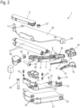
- the housing 2 is made up of several parts and comprises a carrier 20 to which a U-shaped housing part 21 is fixed.
- An insert element 22 is inserted into the housing part 21, on which a curved guide 10 and a control curve 11 are formed.
- the insert element 22 is arranged with a web 12 in alignment with an opening 23 on the housing part 21, so that a screw 13 can be screwed through the opening 23, the web 12 into a tab 28 of the carrier 20, so that they form a firmly connected unit.
- further screws 13 are inserted into the housing part 21 in order to fix the insert element 22 in the housing part 21.
- Two openings 24 are arranged in alignment on the housing part 21, through which a two-part bearing element 25 is inserted to form a rotation axis.
- the lever 3 is arranged around the bearing element 25 and is designed as a two-armed lever 3 and has a bearing receptacle 9.
- Two holders 8 in the form of pins are formed on the lever 3, to which one end of a spring is fixed, the springs together forming a force accumulator 5.
- a force accumulator 5 Two holders 8 in the form of pins are formed on the lever 3, to which one end of a spring is fixed, the springs together forming a force accumulator 5.
- only one spring or more than two springs can be used to preload the lever 3 in a direction of rotation.
- the springs are fixed with the opposite end to holding sections 7 that protrude from the carrier 20.
- other types of force accumulators can also be used instead of coil springs.
- the lever 3 comprises a control section 30 which is arranged inside the housing 2. On the opposite side of the rotation axis, an actuating section 31 is formed, to which the contact element 34 is fixed. A receptacle for the rotationally fixed arrangement of a nut 32 is formed on the actuating section 31, into which an adjusting element 33 in the form of a screw is screwed.
- the adjusting element 33 is rotatable but axially immovable, inserted on the contact element 34, so that by rotating the adjusting element 33, the contact element 34 can be adjusted in the axial direction of the adjusting element 33 relative to the actuating section 31.
- a slider 15 is slidably mounted on the control section 30 and has a latch 16 and a control element 17.
- the latch 16 is guided in the curved guide 10 on the insert element 22, while the control element 17 is guided on the control curve 11.
- a pressure piece 19 is rotatably mounted on the control section 30 and is held by a fastening part 18 that is fixed to the control section 30.
- the pressure piece 19 is guided by a driver on a further control cam 40 that is fixed to the insert element 22.
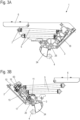
- the ejection device 1 is shown in a starting position in which the energy accumulator 5 is tensioned and the locking mechanism is in a locked position.
- the activator 4 rests against the contact element 34.
- the latch 16 is held on a locking receptacle 50 of the curved guide 10, and the control element 17 is arranged in the control curve 11.
- a movable furniture part coupled to the activator 4 is in a closed or starting position.
- the ejection device 1 is shown ejecting a movable furniture part (not shown).
- the lever 3 is moved by the force of the energy storage device in Figure 5A counterclockwise and in Figure 5B clockwise and thus acts on the activator 4, which moves the movable furniture part from the starting position in the opening direction.
- the lever 3 pivots so far that the bolt 16 moves out of the curve guide 10, which is open and has an extension channel and an entry channel.
- the bolt 16 is still in the extension channel of the curve guide 10
- the latch 16 on the slider 15 has moved away from the curved guide 10.
- the movable furniture part moves with the activator 4 at the Figures 5B to 5D from right to left, and the clamping element 6 attached to the movable furniture part reaches the pressure piece 19 attached to the lever 3 in the ejected opening position.
- the control element 17 moves along the control curve 11 and displaces the slide 15 in the radial direction outwards, as is the case with the Figures 5B and 5C can be removed until the control element 17 is arranged in a channel which extends essentially in the circumferential direction around the axis of rotation 26. From this opening position, the movable furniture part can now be moved either in the closing direction or in the opening direction, in both cases the lever 3 is pivoted back into the starting position and the locking mechanism is brought into the starting position.
- the activator 4 By releasing the movable furniture part, the activator 4 is moved in the opposite direction by the force of the energy storage device 5, whereby a locking projection 58 via a stop 56 pushes the latch 16 into the locking receptacle 50, where the latch 16 locks.
- the Figure 6D thus corresponds to the starting position and the closing position of the movable furniture part, which can be unlocked again by pressing it into an overpressure position, as described above.
- the ejection device 1 can be removed from the Figure 5D shown position, instead of moving the movable furniture part in the closing direction, it can also be tightened by moving the movable furniture part in the opening direction, as shown in the Figures 7A to 7E shown.
- the clamping element 6 is pressed with a roller 61 against the pressure piece 19, which is held on the lever 3, so that the lever 3 is in the Figures 7A and 7B clockwise and in the Figures 7C to 7E rotates anti-clockwise.
- the lever 3 is locked again on the locking mechanism via the latch 16, and the movable furniture part to which the clamping element 6 is fixed can now move further in the opening direction. Part of the movement in the opening direction is thus used to lock the lever 3 again with the tensioned energy storage device 5. Even if the locking were to fail, the lever 3 could not swing back, since the clamping element 6 is strip-shaped and forms a stop that prevents the lever 3 from rotating backwards.
- FIG 7C the beginning of the clamping process is shown by a movement of the clamping element 6 on the movable furniture part in the opening direction.
- the clamping element 6 presses with the roller 61 against the pressure piece 19, which moves the lever 3 with the slide 15 towards the curved guide 10.
- the control element 17 on the slide 15 slides along the control curve 11 and moves the slide 15 in a predetermined rotational position radially to the rotation axis 26 in order to position the bolt 16 so that it enters the entry channel of the curved guide 10.
- the entry situation is in Figure 7D shown, and the guidance of the slide 15 is now transferred from the control element 17 to the latch 16.
- the latch 16 moves further along the curved guide 10 until it is arranged adjacent to the locking receptacle 50.
- the pressure piece 19 is used, which can be pivoted relative to the lever 3 and presses the latch 16 onto the locking receptacle 50 through the pivoting movement.
- a guide surface 29 formed on the pressure piece 19 is arranged inclined to the circumferential direction about the axis of rotation 26 and slides along a surface of the slide 15 so that it is displaced radially towards the axis of rotation 26 and the latch 16 is deposited in the locking receptacle 50 without the lever 3 being moved into the over-press position.
- the pivoting ability of the pressure piece 19 is thus used to place the bolt 16 on the locking receptacle 50, so that the locking mechanism is locked during the opening movement of the movable furniture part.
- the spring-loaded locking projection 58 can thereby move over the stop 56 to enable the bolt 16 to be placed in the locking receptacle 50 without the lever moving backwards.
- Figure 7E In the position shown, the movable furniture part can then be moved further in the opening direction with the clamping element 6.
- the pivoting movement of the pressure piece 19 relative to the lever 3 is determined with reference to the Figures 8A and 8B explained.
- the lever 3 is in a released position and is pivoted anti-clockwise by the energy storage device 5.
- the pressure piece 19 is designed as a two-armed lever and is pivotably mounted about an axis 42 relative to the lever 3. A first part of the pressure piece 19 can come into engagement with the clamping element 6 during clamping, and a control section 41 arranged on the opposite side of the axis 42 slides along a control curve 40 which is fixed to the housing 2.
- the control curve 40 is designed such that when the lever 3 is moved from the starting position, the pressure piece 19 is rotated anti-clockwise relative to the lever 3.
- FIGs 10A and 10B an adjustment of the locking mechanism is shown in order to change the starting position of the ejection device and thus the position of the movable furniture part in the closed position.
- the adjusting element 33 designed as a screw, is held by a thread in the non-rotatable nut 32 and is arranged rotatably but axially immovably in the contact element 34.
- the contact element 34 is located in Figure 10A near the actuating section 31 of the lever 3. If the adjusting element 33 is now rotated, the contact element 34 is moved to a distance from the actuating section 31, as shown in Figure 10B is shown.
- the actuating element 33 moves with the contact element 34 in the axial direction of the threaded section and also presses the activator 4 relative to the housing 2 in the opening direction. This allows the position of the activator 4 and thus of the movable furniture part to be set in the starting position.
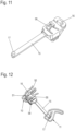
- the slider 15 comprises an elongated web, on one end of which the control element 17 is arranged in the form of a pin.
- the latch 16 is provided, which is designed as a projection, for example with a rectangular shape, although another shape can also be used.
- Adjacent to the latch 16, a locking projection 58 is held on a locking web.
- the locking projection 58 is designed to be spring-loaded via the locking web. It is an additional switching element for tensioning when closing (cf. Fig. 6C - 6D and is tensioned when opening Fig. 7D - 7E spring-loaded and is inoperable for this direction of movement of the bolt 16.
- FIG 12 the locking mechanism is shown with the cam guide 10 and the control cam 11 together with the slide 15.
- the control element 17 is located in every position of the lever 3 within the control cam 11, but only takes over the guidance for a certain angle range of the slide 15.
- the cam guide 10 is open and the latch 16 only engages in the cam guide 10 adjacent to the starting position. In the starting position shown, the latch 16 is held on the locking receptacle 50. Unlocking of the locking mechanism is only possible if the slide 15 is moved radially inwards by moving the latch 16 against the run-on slope 51, so that the locking projection 58 can be moved past the stop 56.
- the locking projection 58 is on a flexible web and can thus travel over a wall of the curve guide 10 in one direction.
- the curved guide 10 is shown in detail, which has an entry channel 52 that leads to the locking receptacle 50 that is formed on an island within the curved guide 10. From the entry channel 52, the bolt 16 can be moved to a slope 53 so that the bolt 16 is positioned adjacent to the locking receptacle 50. Next to the slope 53 there is a first overpressure channel 54 into which the bolt 16 can be inserted when the movable furniture part is moved into an overpressure position. If the furniture is relieved again in the overpressure position, the bolt 16 is moved via the locking projection 58 through the stop 56 into the locking receptacle 50.
- the bolt 16 can be moved against the run-up slope 51 into a second overpressure channel 55, which forms a receptacle next to the run-up slope 51 for the bolt. From this second overpressure channel 55, the latch 16 can then be moved into the extension channel 57 by the force of the energy accumulator 50.
- the stop 56 is formed on an outer side of the extension channel 57.
- control cam 11 for the control element 17 is shown, which is closed and has several guide walls in order to move the control element 17 radially inwards or outwards depending on the rotational position of the lever 3, as described above.
- the ejection device 1 is shown as it is installed on a piece of furniture 80.
- the furniture 80 comprises a furniture body 81 and a movable furniture part 82 in the form of a drawer, which is held so that it can move on a pull-out guide 83 on opposite sides.
- the clamping element 6 and the activator 4 are fixed to the movable furniture part 82.
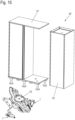
- FIG 16 another piece of furniture 90 is shown, which has a furniture body 91 in the form of a cupboard with a base and a top, between which a movable furniture part 92 in the form of a rotating piece of furniture is held.
- the movable furniture part 92 can be rotated along a guide device 93 stored, and two ejection devices 1 are provided in order to be able to eject the movable furniture part 92 from one end position each, which corresponds to a closed position.
- the movable furniture part 92 can be locked in two end positions.
- the ejection device 1 can also be used for other furniture or household appliances in order to be able to lock a movable furniture part in a starting position and then eject it by unlocking it, wherein the ejection can be designed both as a linear movement and as a pivoting or rotary movement.
Landscapes
- Engineering & Computer Science (AREA)
- Mechanical Engineering (AREA)
- Closing And Opening Devices For Wings, And Checks For Wings (AREA)
Abstract
Description
- Die vorliegende Erfindung betrifft eine Ausstoßvorrichtung mit einem um eine Drehachse drehbar an einem Gehäuse gelagerten Hebel, der über einen Kraftspeicher in eine Drehrichtung vorgespannt ist, und einer Rastmechanik, um den Hebel mit gespanntem Kraftspeicher lösbar zu verriegeln, wobei die Rastmechanik eine Kurvenführung mit einer Rastaufnahme für einen bewegbar in der Kurvenführung verfahrbaren Riegel umfasst, und der Hebel einen Betätigungsabschnitt mit einem Kontaktelement aufweist, das mit einem Aktivator eines bewegbaren Möbelteils zum Auswerfen des bewegbaren Möbelteils beim Drehen des Hebels durch die Kraft des Kraftspeichers in Eingriff bringbar ist.
- Die
EP 2 690 986 offenbart eine Vorrichtung zum Auswerfen eines bewegbaren Möbelteils mit einem schwenkbaren Ausstoßhebel, der in einer Position mit gespanntem Kraftspeicher verrastbar ist. Beim Öffnen des bewegbaren Möbelteils wird eine Kontaktrolle entlang einer Führungsbahn bewegt, um den Kraftspeicher zu spannen oder zu entspannen. Dadurch kann das bewegbare Möbelteil in einer Öffnungsposition verrastet werden. Die Ausstoßvorrichtung ist vergleichsweise voluminös aufgebaut und umfasst eine Vielzahl von Bauteilen. Zudem besteht das Problem, dass das bewegbare Möbelteil einen relativ großen Abstand zu dem stationären Möbelkorpus besitzen muss, damit eine Entriegelung der Ausstoßvorrichtung erfolgen kann. - Es ist daher Aufgabe der vorliegenden Erfindung, eine Ausstoßvorrichtung zu schaffen, die eine präzise Entriegelung einer Rastmechanik bei geringen Schaltwegen gewährleistet.
- Diese Aufgabe wird mit einer Ausstoßvorrichtung mit den Merkmalen des Anspruches 1 gelöst.
- Die erfindungsgemäße Ausstoßvorrichtung umfasst einen drehbar gelagerten Hebel, der über ein Kontaktelement ein bewegbares Möbelteil über einen Kraftspeicher auswerfen kann und über eine Rastmechanik in einer Position mit gespanntem Kraftspeicher lösbar verriegelbar ist. Die Rastmechanik umfasst erfindungsgemäß eine Steuerkurve, in der ein Steuerelement geführt ist, das mit dem Riegel verbunden ist. Das Steuerelement und der Riegel können aneinander fixiert oder an einem Bauteil ausgebildet sein. Die Steuerkurve ist dabei näher an der Drehachse angeordnet als die Kurvenführung.
- Vorzugsweise ist das Kontaktelement an dem Betätigungsabschnitt des Hebels mit einem geringeren Abstand zur Drehachse versehen als die Rastaufnahme für den Riegel. Dadurch findet eine Übersetzung statt, so dass mit einer geringfügigen Eindrückbewegung des bewegbaren Möbelteils an dem Kontaktelement ein Riegel an der Rastaufnahme der Rastmechanik um eine größere Wegstrecke bewegt wird, weshalb auch bei einer geringen Eindrückbewegung eine zuverlässige Entriegelung der Rastmechanik erfolgen kann. Das Übersetzungsverhältnis zwischen der Bewegung des Kontaktelementes und der Bewegung des Riegels oder der Rastaufnahme der Rastmechanik hängt von dem Abstand zur Drehachse des Hebels ab und ist bevorzugt mindestens 50 % zu der Rastmechanik größer als zu dem Kontaktelement. Zudem kann über die Übersetzung auch eine hohe Kraft auf das bewegbare Möbelteil aufgebracht werden, was gerade bei schweren Möbelteilen vorteilhaft ist.
- Die Kurvenführung kann beispielsweise offen ausgebildet sein, so dass der Riegel sich je nach Drehposition des Hebels innerhalb oder außerhalb der Kurvenführung befindet. Die Steuerkurve ist bevorzugt geschlossen ausgebildet, und das Steuerelement befindet sich in jeder Drehposition des Hebels innerhalb der Steuerkurve. Der Hebel kann beispielsweise um einen Winkelbereich zwischen 40° bis 140° zwischen zwei Endpositionen verschwenkbar sein, je nach Öffnungsweg für das bewegbare Möbelteil. Durch die offene Ausbildung der Kurvenführung kann diese in sehr kompakter Bauweise ausgebildet sein, da der Riegel nur dann in der Kurvenführung angeordnet ist, wenn dieser kurz vor Erreichen der Verriegelungsposition angekommen ist, beispielsweise in einem Winkelbereich zwischen 5° und 15° vor Erreichen der verrasteteten Position des Hebels. In dem übrigen Schwenkbereich des Hebels kann der Riegel außerhalb der Kurvenführung angeordnet sein. Das Steuerelement hingegen befindet sich bevorzugt während des kompletten Schwenkbereiches des Hebels innerhalb der Steuerkurve, so dass über die Steuerkurve die Position des Riegels gesteuert wird und ein Einfädeln des Riegels in die Kurvenführung erleichtert wird.
- Die Kurvenführung weist bevorzugt benachbart zu der Rastaufnahme eine Anlaufschräge auf, so dass die Rastmechanik durch Eindrücken des Hebels gegen die Kraft des Kraftspeichers entriegelbar ist. Der Schaltweg zum Entriegeln des Riegels über die Anlaufschräge kann kurz ausgebildet sein, beispielsweise zwischen 1 mm bis 5 mm.
- In einer weiteren Ausgestaltung ist der Riegel verschiebbar an dem Hebel gehalten, und an dem Gehäuse ist die Kurvenführung angeordnet. Optional kann die Rastmechanik auch so gestaltet sein, dass die Kurvenführung an dem Hebel fixiert ist und der Riegel an dem Gehäuse. Vorzugsweise ist jedoch der Riegel verschiebbar an dem Hebel gehalten, insbesondere können der Riegel und das Steuerelement an einem gemeinsamen Schieber vorgesehen sein, der in eine radiale Richtung linear an dem Hebel geführt ist.
- Der Hebel ist vorzugsweise als zweiarmiger Hebel ausgebildet und umfasst zwischen dem Betätigungsabschnitt mit dem Kontaktelement und der Rastaufnahme eine Drehachse. Dabei müssen sich das Kontaktelement und die Ratsaufnahme nicht exakt diametral zur Drehachse gegenüberliegen, sondern können auch in anderen Winkeln angeordnet sein, wenn die Drehachse als Mittelpunkt angesehen wird.
- Für eine optimierte Einstellung der Ausstoßvorrichtung kann an dem Betätigungsabschnitt das Kontaktelement über ein Stellelement verstellbar gehalten sein, so dass der Blendenspalt oder ein anderer Spalt zwischen dem bewegbaren Möbelteil und einem Möbelkorpus verstellbar ist.
- Die Ausstoßvorrichtung lässt sich vorzugsweise durch eine Bewegung des Hebels in gegenüberliegende Richtungen spannen. Der Hebel kann aus einer Position mit entspanntem Kraftspeicher somit wahlweise durch den Aktivator bei Bewegung des bewegbaren Möbelteils in Schließrichtung oder durch ein Spannelement bei einer Bewegung des bewegbaren Möbelteils in Öffnungsrichtung in die Ausgangsposition mit gespanntem Kraftspeicher bewegt werden. Unabhängig davon, ob der Benutzer das bewegbare Möbelteil in Öffnungs- oder Schließrichtung bewegt, kann dadurch die Rastmechanik wieder gespannt und der Riegel in die Rastaufnahme abgelegt werden.
- Um ein möglichst geräuscharmes Ablegen des Riegels an der Rastaufnahme zu gewährleisten kann an dem Hebel ein bewegbares Druckstück gehalten sein, mittels dem der Riegel bei einer Drehbewegung des Hebels zu der Rastaufnahme bewegbar ist. Das Druckstück kann dabei drehbar an dem Hebel gelagert sein, um den Riegel bei Erreichen der Rastaufnahme schräg oder senkrecht zur Spannrichtung zu bewegen. Das Druckstück an dem Hebel kann ferner durch eine an dem Gehäuse angeordnete Steuerkurve bewegbar sein und wird bevorzugt bei einer Ausstoßbewegung durch Drehung des Hebels wieder in eine Ausgangsposition gebracht.
- Das Spannelement für den Spannmechanismus beim Bewegen des bewegbaren Möbelteils in Öffnungsrichtung ist vorzugsweise leistenförmig ausgebildet und bildet einen Anschlag für den Hebel aus, damit dieser bei fehlender Verrastung der Rastmechanik verhindert, dass der Hebel sich weiter in Öffnungsrichtung dreht. Dadurch wird verhindert, dass der Hebel durch eine Fehlbetätigung zu weit in eine Blockadeposition verschwenkt wird, und der Hebel kann beim Schließen des bewegbaren Möbelteils in die Rastposition bewegt werden.
- Die erfindungsgemäße Ausstoßvorrichtung wird vorzugsweise bei einem Möbel eingesetzt, das einen Möbelkorpus und ein bewegbares Möbelteil umfasst. Das bewegbare Möbelteil kann beispielsweise als Schubkasten, Tür, Klappe oder als Regal oder Schrankteil ausgebildet sein, das an einem Möbelkorpus bewegbar gehalten ist.
- Die Erfindung wird nachfolgend anhand eines Ausführungsbeispiels mit Bezug auf die beigefügten Zeichnungen näher erläutert. Es zeigen:
- Figur 1
- eine perspektivische Ansicht einer erfindungsgemäßen Ausstoßvorrichtung in der montierten Position;
- Figur 2
- eine Explosionsdarstellung der Ausstoßvorrichtung der
Figur 1 ; - Figuren 3A und 3B
- zwei Ansichten der Ausstoßvorrichtung in einer Ausgangsposition mit gespanntem Kraftspeicher;
- Figuren 4A bis 4C
- mehrere Ansichten der Ausstoßvorrichtung der
Figur 1 beim Auslösen der Rastmechanik; - Figuren 5A bis 5D
- mehrere Ansichten beim Ausstoßen eines bewegbaren Möbelteils durch die Ausstoßvorrichtung;
- Figuren 6A bis 6D
- mehrere Ansichten beim Spannen der Ausstoßvorrichtung durch Bewegen des Hebels in Schließrichtung;
- Figuren 7A bis 7E
- mehrere Ansichten der Ausstoßvorrichtung beim Spannen des Hebels durch Bewegen des bewegbaren Möbelteils in Öffnungsrichtung;
- Figuren 8A und 8B
- zwei Ansichten mit dem Druckstück an dem Hebel in unterschiedlichen Positionen;
- Figuren 9
- eine Ansicht der Ausstoßvorrichtung mit dem Spannelement im Bereich des Hebels;
- Figuren 10A und 10B
- zwei Ansichten des Hebels mit dem Kontaktelement in unterschiedlichen Positionen;
- Figur 11
- eine perspektivische Ansicht des Schiebers mit dem Riegel und dem Steuerelement;
- Figur 12
- eine Ansicht des Schiebers und der Kurvenführung und der Steuerkurve;
- Figur 13
- eine Detailansicht der Kurvenführung;
- Figur 14
- eine Detailansicht der Steuerkurve;
- Figuren 15A und 15B
- zwei Ansichten eines ersten Möbels mit einer erfindungsgemäßen Ausstoßvorrichtung, und
- Figur 16
- eine Ansicht eines zweiten Möbels mit einer erfindungsgemäßen Ausstoßvorrichtung.
- Eine Ausstoßvorrichtung 1 umfasst ein Gehäuse 2, an dem ein Hebel 3 drehbar gelagert ist. Der Hebel 3 wirkt über ein Kontaktelement 34 auf einen Aktivator 4 ein, der mit einem bewegbaren Möbelteil koppelbar ist. Der Hebel 3 ist durch einen Kraftspeicher 5 in eine Drehrichtung in Öffnungsrichtung des bewegbaren Möbelteils vorgespannt, wobei der Hebel 3 durch eine Rastmechanik mit gespanntem Kraftspeicher verrastet werden kann. An der Ausstoßvorrichtung 1 ist ferner ein Spannelement 6 dargestellt, das an dem bewegbaren Möbelteil fixiert ist.
- In
Figur 2 ist die Ausstoßvorrichtung 1 in einer Explosionsdarstellung gezeigt. Das Gehäuse 2 ist mehrteilig ausgebildet und umfasst einen Träger 20, an dem ein U-förmig gebogenes Gehäuseteil 21 fixiert ist. In das Gehäuseteil 21 ist ein Einlageelement 22 eingefügt, an dem eine Kurvenführung 10 und eine Steuerkurve 11 ausgebildet sind. Das Einlageelement 22 ist mit einem Steg 12 fluchtend zu einer Öffnung 23 an dem Gehäuseteil 21 angeordnet, so dass eine Schraube 13 durch die Öffnung 23, den Steg 12 in eine Lasche 28 des Trägers 20 eindrehbar ist, so dass diese eine fest verbundene Einheit bilden. Zudem sind weitere Schrauben 13 an dem Gehäuseteil 21 eingefügt, um das Einlageelement 22 in dem Gehäuseteil 21 zu fixieren. - An dem Gehäuseteil 21 sind zwei Öffnungen 24 fluchtend angeordnet, durch die ein zweiteiliges Lagerelement 25 zur Ausbildung einer Drehachse durchgesteckt ist. Um das Lagerelement 25 ist der Hebel 3 angeordnet, der als zweiarmiger Hebel 3 ausgebildet ist und eine Lageraufnahme 9 aufweist.
- An dem Hebel 3 sind zwei Halter 8 in Form von Zapfen ausgebildet, an denen ein Ende einer Feder fixiert ist, wobei die Federn zusammen einen Kraftspeicher 5 ausbilden. Optional kann statt zwei Federn auch nur eine Feder oder mehr als zwei Federn verwendet werden, um den Hebel 3 in eine Drehrichtung vorzuspannen. Die Federn sind mit dem gegenüberliegenden Ende an Halteabschnitten 7 fixiert, die von dem Träger 20 hervorstehen. Ferner können statt Schraubenfedern auch andere Arten von Kraftspeichern verwendet werden.
- Der Hebel 3 umfasst einen Steuerabschnitt 30, der innerhalb des Gehäuses 2 angeordnet ist. Auf der gegenüberliegenden Seite der Drehachse ist ein Betätigungsabschnitt 31 ausgebildet, an dem das Kontaktelement 34 fixiert ist. An dem Betätigungsabschnitt 31 ist dabei eine Aufnahme zur drehfesten Anordnung einer Mutter 32 ausgebildet, in die ein Stellelement 33 in Form einer Schraube eingedreht ist. Das Stellelement 33 ist drehbar, aber axial unverschieblich, an dem Kontaktelement 34 eingefügt, so dass durch Drehen des Stellelementes 33 das Kontaktelement 34 in axiale Richtung des Stellelementes 33 relativ zu dem Betätigungsabschnitt 31 verstellbar ist.
- An dem Steuerabschnitt 30 ist ein Schieber 15 verschiebbar gehalten, der einen Riegel 16 und ein Steuerelement 17 aufweist. Der Riegel 16 ist dabei in der Kurvenführung 10 an dem Einlageelement 22 geführt, während das Steuerelement 17 an der Steuerkurve 11 geführt ist.
- An dem Steuerabschnitt 30 ist ferner ein Druckstück 19 drehbar gelagert, das über ein Befestigungsteil 18 gehalten ist, das an dem Steuerabschnitt 30 fixiert ist. Das Druckstück 19 ist mit einem Mitnehmer an einer weiteren Steuerkurve 40 geführt, die an dem Einlageelement 22 fixiert ist.
- In den
Figuren 3A und 3B ist die Ausstoßvorrichtung 1 in einer Ausgangsposition gezeigt, in der der Kraftspeicher 5 gespannt ist und die Rastmechanik sich in einer verriegelten Position befindet. Der Aktivator 4 liegt an dem Kontaktelement 34 an. Der Riegel 16 ist an einer Rastaufnahme 50 der Kurvenführung 10 gehalten, und das Steuerelement 17 ist in der Steuerkurve 11 angeordnet. Ein mit dem Aktivator 4 gekoppeltes bewegbares Möbelteil befindet sich in einer Schließ- oder Ausgangsposition. - Soll die Rastmechanik der Ausstoßvorrichtung 1 entriegelt werden, kann gemäß den
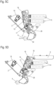
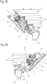
Figuren 4A und 4B das bewegbare Möbelteil und somit der Aktivator 4 gegen die Kraft des Kraftspeichers 5 bewegt werden, so dass der Hebel 3 um eine Drehachse 26 beiFigur 4A im Uhrzeigersinn und bei der Schnittansicht derFigur 4B gegen den Uhrzeigersinn dreht. Diese Drehbewegung bewirkt, dass der Riegel 16 von der Rastaufnahme 50 abgehoben wird und gegen eine Anlaufschräge 51 an der Kurvenführung 10 bewegt wird. Aufgrund des unterschiedlichen Abstandes zu der Drehachse 26 kann die Bewegung des Aktivators 4 geringer ausfallen, da der Riegel 16 durch den größeren Hebelarm mindestens das 1,5-fache an Wegstrecke zurücklegt, beispielsweise zwischen dem 1,8- bis 2,5-fachen. Wenn der Riegel 16 gegen die Anlaufschräge 51 bewegt wird, wird der Schieber 15 relativ zu dem Hebel 3 verschoben, so dass bei einem Loslassen des bewegbaren Möbelteils und des Aktivators 4 der Hebel 3 durch die Kraft des Kraftspeichers 5 in die gegenläufige Richtung dreht, aber der Riegel 16 nicht mehr an der Rastaufnahme 50 verrastet. Die entriegelte Position beim Auslösen ist inFigur 4C gezeigt, und es ist erkennbar, dass der Riegel 16 sich in radiale Richtung des Hebels 3 bewegt hat, so dass der Riegel 16 nicht mehr auf die Rastaufnahme 50 aufläuft, sondern durch einen Auslaufkanal der Kurvenführung 10. - In den
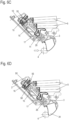
Figuren 5A und 5B ist die Ausstoßvorrichtung 1 beim Ausstoßen eines nicht dargestellten bewegbaren Möbelteils gezeigt. Der Hebel 3 wird durch die Kraft der Kraftspeicher inFigur 5A gegen den Uhrzeigersinn und inFigur 5B im Uhrzeigersinn gedreht und wirkt somit auf den Aktivator 4, der das bewegbare Möbelteil aus der Ausgangsstellung in Öffnungsrichtung bewegt. Der Hebel 3 verschwenkt so weit, dass der Riegel 16 sich aus der Kurvenführung 10 herausbewegt, die offen ausgebildet ist und einen Ausfahrkanal und einen Einfahrkanal aufweist. InFigur 5B befindet sich der Riegel 16 noch in dem Ausfahrkanal der Kurvenführung 10, und in denFiguren 5C und 5D hat sich der Riegel 16 an dem Schieber 15 von der Kurvenführung 10 entfernt. Das bewegbare Möbelteil bewegt sich mit dem Aktivator 4 bei denFiguren 5B bis 5D von rechts nach links, und das an dem bewegbaren Möbelteil angebrachte Spannelement 6 gelangt zu dem an dem Hebel 3 angebrachten Druckstück 19 in der ausgestoßenen Öffnungsposition. Durch die Drehbewegung des Hebels fährt das Steuerelement 17 entlang der Steuerkurve 11 und verschiebt den Schieber 15 in radiale Richtung nach außen, wie dies denFiguren 5B und5C entnehmbar ist, bis das Steuerelement 17 in einem Kanal angeordnet ist, der sich im Wesentlichen in Umfangsrichtung um die Drehachse 26 erstreckt. Aus dieser Öffnungsposition kann das bewegbare Möbelteil nun wahlweise in Schließrichtung oder in Öffnungsrichtung bewegt werden, wobei in beiden Fällen der Hebel 3 wieder in die Ausgangsposition verschwenkt wird und die Rastmechanik in die Ausgangsposition gebracht wird. - In den
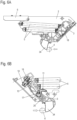
Figuren 6A bis 6D ist der Spannvorgang des Hebels 3 gezeigt, wenn das bewegbare Möbelteil mit dem Aktivator wieder in Schließrichtung bewegt wird. Dann drückt der Aktivator 4 gegen das Kontaktelement 34 und verschwenkt den Hebel 3 inFigur 6A im Uhrzeigersinn und in denFiguren 6B bis 6D gegen den Uhrzeigersinn. Durch den Aktivator 4 wird der Hebel 3 gedreht, und das Steuerelement 17 bewegt sich entlang der Steuerkurve 11 und verschiebt den Schieber 15 in radiale Richtung zu der Drehachse 26 hin. Über die Steuerkurve 11 wird der Riegel 16 so positioniert, dass er in den Einfahrkanal der Kurvenführung 10 gelangt und dort die Führung des Schiebers 15 übernimmt. - In der
Figur 6C ist das bewegbare Möbelteil mit dem Aktivator 4 in einer Überdrückposition gezeigt, und der Hebel 3 wurde so weit verschwenkt, dass der Riegel 16 über die Rastaufnahme 50 entlang der Kurvenführung 10 bewegt wurde. Die Führung des Schiebers 15 wird nun durch den Riegel 16 bestimmt, und das Steuerelement 17 ist funktionslos. - Durch Loslassen des bewegbaren Möbelteils wird der Aktivator 4 durch die Kraft des Kraftspeichers 5 in die gegenläufige Richtung bewegt, wobei ein Rastvorsprung 58 über einen Anschlag 56 den Riegel 16 in die Rastaufnahme 50 schiebt, wo der Riegel 16 verrastet. Die
Figur 6D entspricht somit der Ausgangsposition und der Schließposition des bewegbaren Möbelteils, das durch Eindrücken in eine Überdrückstellung wieder entriegelt werden kann, wie dies oben beschrieben wurde. - Die Ausstoßvorrichtung 1 kann aus der in
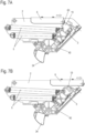
Figur 5D gezeigten Position statt durch Bewegen des bewegbaren Möbelteils in Schließrichtung auch durch ein Bewegen des bewegbaren Möbelteils in Öffnungsrichtung gespannt werden, wie dies in denFiguren 7A bis 7E gezeigt ist. InFigur 7A wird das Spannelement 6 mit einer Rolle 61 gegen das Druckstück 19 gedrückt, das an dem Hebel 3 gehalten ist, so dass sich der Hebel 3 in denFiguren 7A und 7B im Uhrzeigersinn und in denFiguren 7C bis 7E gegen den Uhrzeigersinn dreht. Der Hebel 3 wird an der Rastmechanik über den Riegel 16 wieder verrastet, und das bewegbare Möbelteil, an dem das Spannelement 6 fixiert ist, kann sich nun weiter in Öffnungsrichtung bewegen. Ein Teil der Bewegung in Öffnungsrichtung wird somit genutzt, um den Hebel 3 wieder mit gespanntem Kraftspeicher 5 zu verrasten. Selbst wenn die Verrastung fehlschlagen würde, könnte der Hebel 3 nicht zurückschwenken, da das Spannelement 6 leistenförmig ausgebildet ist und einen Anschlag ausbildet, der eine Rückwärtsdrehung des Hebels 3 verhindert. - In
Figur 7C ist der Beginn des Spannvorganges durch eine Bewegung des Spannelementes 6 an dem bewegbaren Möbelteil in Öffnungsrichtung gezeigt. Das Spannelement 6 drückt mit der Rolle 61 gegen das Druckstück 19, das den Hebel 3 mit dem Schieber 15 zu der Kurvenführung 10 hin bewegt. Das Steuerelement 17 an dem Schieber 15 gleitet entlang der Steuerkurve 11 und bewegt den Schieber 15 in einer vorbestimmten Drehposition radial zu der Drehachse 26, um den Riegel 16 so zu positionieren, dass dieser in den Einfahrkanal der Kurvenführung 10 gelangt. Die Einfahrsituation ist inFigur 7D gezeigt, und die Führung des Schiebers 15 wird nun von dem Steuerelement 17 an den Riegel 16 übergeben. Der Riegel 16 fährt weiter entlang der Kurvenführung 10, bis er benachbart zu der Rastaufnahme 50 angeordnet ist. In dieser Situation kommt das Druckstück 19 zum Einsatz, das relativ zu dem Hebel 3 verschwenkbar ist und durch die Schwenkbewegung den Riegel 16 auf die Rastaufnahme 50 drückt. Eine an dem Druckstück 19 ausgebildete Führungsfläche 29 ist geneigt zur Umfangsrichtung um die Drehachse 26 angeordnet und gleitet entlang einer Oberfläche des Schiebers 15, so dass dieser radial zu der Drehachse 26 hin verschoben wird und der Riegel 16 in der Rastaufnahme 50 abgelegt wird, ohne dass der Hebel 3 in die Überdrückstellung bewegt wird. - Die Verschwenkbarkeit des Druckstückes 19 wird somit genutzt, um den Riegel 16 an der Rastaufnahme 50 abzulegen, so dass eine Verrastung der Rastmechanik während der Öffnungsbewegung des bewegbaren Möbelteils erfolgt. Der federnd ausgeführte Rastvorsprung 58 kann hierbei den Anschlag 56 überfahren um das Ablegen des Riegels 16 in der Rastaufnahme 50 ohne Rückwärtsbewegung des Hebels zu ermöglichen. Aus der in
Figur 7E gezeigten Position kann dann das bewegbare Möbelteil mit dem Spannelement 6 weiter in Öffnungsrichtung bewegt werden. - Die Schwenkbewegung des Druckstückes 19 relativ zu dem Hebel 3 wird mit Bezug auf die
Figuren 8A und8B erläutert. InFigur 8A befindet sich der Hebel 3 in einer ausgelösten Position und wird durch die Kraftspeicher 5 entgegen dem Uhrzeigersinn verschwenkt. Das Druckstück 19 ist als zweiarmiger Hebel ausgebildet und um eine Achse 42 relativ zu dem Hebel 3 verschwenkbar gelagert. Ein erster Teil des Druckstückes 19 kann beim Spannen in Eingriff mit dem Spannelement 6 gelangen, und ein auf der gegenüberliegenden Seite der Achse 42 angeordneter Steuerabschnitt 41 gleitet entlang einer Steuerkurve 40, die an dem Gehäuse 2 festgelegt ist. Die Steuerkurve 40 ist so ausgebildet, dass beim Bewegen des Hebels 3 aus der Ausgangsposition das Druckstück 19 entgegen dem Uhrzeigersinn relativ zu dem Hebel 3 gedreht wird. InFigur 8B wurde das Druckstück 19 relativ zu dem Hebel 3 gedreht und gleitet nun entlang der Steuerkurve 40 weiter zusammen mit dem Hebel 3. Wenn das Druckstück 19 bei einem Spannvorgang durch das bewegbare Möbelteil und das Spannelement 6 mit einer Kraft beaufschlagt wird, wie dies in denFiguren 7C bis 7E gezeigt ist, dann wird das Druckstück 19 durch die Steuerkurve 40 wieder an derselben Stelle relativ zum Hebel 3 verschwenken und dabei den Riegel 16 in die Rastaufnahme 50 drücken. - In
Figur 9 ist eine Position der Ausstoßvorrichtung 1 gezeigt, bei der der Hebel 3 durch das Spannelement 6 zwar in die Ausgangsposition gespannt wurde, aber aus irgendwelchen Gründen keine Verrastung des Riegels 16 an der Rastaufnahme 50 stattgefunden hat. Wie durch den Pfeil symbolisch angedeutet, drückt der Hebel 3 nun gegen den Uhrzeigersinn aufgrund der Wirkung des Kraftspeichers 5. Der Hebel 3 kann dennoch nicht aus der gespannten Position bewegt werden, da das Druckstück 19 gegen das Spannelement 6 anschlägt, das leistenförmig ausgebildet ist und eine untere Anschlagsfläche ausbildet. Insofern erfolgt kein ruckartiges Verschwenken des Hebels 3 durch die Kraft des Kraftspeichers 5. Der Hebel 3 kann dann bei Überfahren des Spannelementes 6 wieder gegen die Rolle 61 drücken, so dass die inFigur 5D gezeigte Position mit entspanntem Kraftspeicher 5 erreicht wird. Eine Blockierung des Spannelementes 6 bei der Bewegung in Schließrichtung wird somit ausgeschlossen. - In den
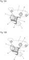
Figuren 10A und 10B ist eine Verstellung der Rastmechanik gezeigt, um die Ausgangsposition der Ausstoßvorrichtung und somit die Position des bewegbaren Möbelteils in der Schließposition zu verändern. Das als Schraube ausgebildete Stellelement 33 ist mit einem Gewinde in der drehfesten Mutter 32 gehalten und ist drehbar aber axial unverschieblich in dem Kontaktelement 34 angeordnet. Das Kontaktelement 34 befindet sich inFigur 10A nahe dem Betätigungsabschnitt 31 des Hebels 3. Wird das Stellelement 33 nun gedreht, gelangt das Kontaktelement 34 in einen Abstand zu dem Betätigungsabschnitt 31, wie dies inFigur 10B gezeigt ist. Dabei bewegt sich das Stellelement 33 mit dem Kontaktelement 34 in axiale Richtung des Gewindeabschnittes und drückt den Aktivator 4 ebenfalls relativ zu dem Gehäuse 2 in Öffnungsrichtung. Dadurch kann die Position des Aktivators 4 und somit des bewegbaren Möbelteils in der Ausgangsposition eingestellt werden. - In
Figur 11 ist der Schieber 15 im Detail gezeigt. Der Schieber 15 umfasst einen länglichen Steg, an dem an einem Ende das Steuerelement 17 in Form eines Zapfens angeordnet ist. Auf der gegenüberliegenden Seite ist der Riegel 16 vorgesehen, der als Vorsprung ausgebildet ist, beispielsweise mit rechteckiger Form, wobei auch eine andere Form eingesetzt werden kann. Benachbart zu dem Riegel 16 ist ein Rastvorsprung 58 an einem Raststeg gehalten. Der Rastvorsprung 58 ist über den Raststeg federnd ausgeführt. Er ist ein zusätzliches Schaltelement für das Spannen beim Schließen vgl.Fig. 6C - 6D und wird beim Spannen beim ÖffnenFig. 7D - 7E federnd überfahren und ist für diese Bewegungsrichtung des Riegels 16 funktionslos. - In
Figur 12 ist die Rastmechanik mit der Kurvenführung 10 und der Steuerkurve 11 zusammen mit dem Schieber 15 gezeigt. Das Steuerelement 17 befindet sich in jeder Position des Hebels 3 innerhalb der Steuerkurve 11, übernimmt aber nur für einen gewissen Winkelbereich des Schiebers 15 die Führung. Die Kurvenführung 10 ist offen ausgebildet, und es erfolgt nur benachbart zu der Ausgangsposition ein Eingriff des Riegels 16 in die Kurvenführung 10. In der dargestellten Ausgangsposition ist der Riegel 16 an der Rastaufnahme 50 gehalten. Eine Entriegelung der Rastmechanik wird nur dann ermöglicht, wenn sich der Schieber 15 durch Bewegen des Riegels 16 gegen die Anlaufschräge 51 radial nach innen verschiebt, so dass der Rastvorsprung 58 an dem Anschlag 56 vorbei bewegt werden kann. Der Rastvorsprung 58 ist an einem biegbaren Steg angeordnet und kann somit eine Wand der Kurvenführung 10 in eine Richtung überfahren. - In
Figur 13 ist die Kurvenführung 10 im Detail gezeigt, die einen Einfahrkanal 52 aufweist, der zu der Rastaufnahme 50 führt, die an einer Insel innerhalb der Kurvenführung 10 ausgebildet ist. Von dem Einfahrkanal 52 kann der Riegel 16 zu einer Schräge 53 bewegt werden, damit der Riegel 16 benachbart zu der Rastaufnahme 50 positioniert wird. Neben der Schräge 53 befindet sich ein erster Überdruckkanal 54, in den der Riegel 16 eingefügt werden kann, wenn das bewegbare Möbelteil in eine Überdrückstellung bewegt wird. Wird das Möbel in der Überdückstellung wieder entlastet, wird der Riegel 16 über den Rastvorsprung 58 durch den Anschlag 56 in die Rastaufnahme 50 bewegt. Von der Rastaufnahme 50 kann der Riegel 16 gegen die Anlaufschräge 51 in einen zweiten Überdruckkanal 55 bewegt werden, der eine Aufnahme neben der Anlaufschräge 51 für den Riegel ausbildet. Von diesem zweiten Überdruckkanal 55 kann der Riegel 16 dann durch die Kraft des Kraftspeichers 50 in den Ausfahrkanal 57 bewegt werden. An dem Ausfahrkanal 57 ist der Anschlag 56 an einer Außenseite ausgebildet. - In
Figur 14 ist die Steuerkurve 11 für das Steuerelement 17 gezeigt, die geschlossen ausgebildet ist und mehrere Führungswände aufweist, um das Steuerelement 17 je nach Drehposition des Hebels 3 radial nach innen oder außen zu verschieben, wie dies vorstehend beschrieben wurde. - In den
Figuren 15A und 15B ist die Ausstoßvorrichtung 1 gezeigt, wie sie an einem Möbel 80 eingebaut wird. Das Möbel 80 umfasst einen Möbelkorpus 81 und ein bewegbares Möbelteil 82 in Form eines Schubkastens, der an gegenüberliegenden Seiten jeweils an einer Auszugsführung 83 verfahrbar gehalten ist. An dem bewegbaren Möbelteil 82 sind das Spannelement 6 und der Aktivator 4 fixiert. Dadurch kann die Auszugsführung 83 an einer Seitenwand des Möbelkorpus 81 montiert werden, an der auch das Gehäuse 2 der Ausstoßvorrichtung 1 fixiert ist, so dass der bewegbare Hebel 3 auf den Aktivator 4 und das Spannelement 6 wirkt, die an dem bewegbaren Möbelteil 82 montiert sind. - In
Figur 16 ist ein weiteres Möbel 90 gezeigt, das einen Möbelkorpus 91 in Form eines Schrankes mit einem Boden und einem Oberboden aufweist, zwischen denen ein bewegbares Möbelteil 92 in Form eines Drehmöbels gehalten ist. Das bewegbare Möbelteil 92 ist entlang einer Führungseinrichtung 93 drehbar gelagert, und es sind zwei Ausstoßvorrichtungen 1 vorgesehen, um das bewegbare Möbelteil 92 aus jeweils einer Endposition, die einer Schließposition entspricht, auswerfen zu können. Das bewegbare Möbelteil 92 ist in zwei Endpositionen verrastbar. - Die Ausstoßvorrichtung 1 kann auch für andere Möbel oder Haushaltsgeräte eingesetzt werden, um ein bewegbares Möbelteil in einer Ausgangsposition verrasten zu können und dieses dann durch eine Entriegelung auswerfen zu können, wobei das Auswerfen sowohl als lineare Bewegung als auch als Schwenk- oder Drehbewegung ausgebildet sein kann.
-
- 1
- Ausstoßvorrichtung
- 2
- Gehäuse
- 3
- Hebel
- 4
- Aktivator
- 5
- Kraftspeicher
- 6
- Spannelement
- 7
- Halteabschnitt
- 8
- Halter
- 9
- Lageraufnahme
- 10
- Kurvenführung
- 11
- Steuerkurve
- 12
- Steg
- 13
- Schraube
- 15
- Schieber
- 16
- Riegel
- 17
- Steuerelement
- 18
- Befestigungsteil
- 19
- Druckstück
- 20
- Träger
- 21
- Gehäuseteil
- 22
- Einlageelement
- 23
- Öffnung
- 24
- Öffnung
- 25
- Lagerelement
- 26
- Drehachse
- 28
- Lasche
- 29
- Führungsfläche
- 30
- Steuerabschnitt
- 31
- Betätigungsabschnitt
- 32
- Mutter
- 33
- Stellelement
- 34
- Kontaktelement
- 40
- Steuerkurve
- 41
- Steuerabschnitt
- 42
- Achse
- 50
- Rastaufnahme
- 51
- Anlaufschräge
- 52
- Einfahrkanal
- 53
- Schräge
- 54
- Überdruckkanal
- 55
- Überdruckkanal
- 56
- Anschlag
- 57
- Ausfahrkanal
- 58
- Rastvorsprung
- 61
- Rolle
- 80
- Möbel
- 81
- Möbelkorpus
- 82
- Möbelteil
- 83
- Auszugsführung
- 90
- Möbel
- 91
- Möbelkorpus
- 92
- Möbelteil
- 93
- Führungseinrichtung
Claims (14)
- Ausstoßvorrichtung (1) mit einem um eine Drehachse (26) drehbar an einem Gehäuse (2) gelagerten Hebel (3), der über einen Kraftspeicher (5) in eine Drehrichtung vorgespannt ist, und einer Rastmechanik, um den Hebel (3) mit gespanntem Kraftspeicher (5) lösbar zu verriegeln, wobei die Rastmechanik eine Kurvenführung (10) mit einer Rastaufnahme (50) für einen bewegbar in der Kurvenführung (10) verfahrbaren Riegel (16) umfasst, und der Hebel (3) einen Betätigungsabschnitt (31) mit einem Kontaktelement (34) aufweist, das mit einem Aktivator (4) eines bewegbaren Möbelteils (82, 92) zum Auswerfen des bewegbaren Möbelteils (82, 92) beim Drehen des Hebels (3) durch die Kraft des Kraftspeichers (5) in Eingriff bringbar ist, dadurch gekennzeichnet, dass die Rastmechanik eine Steuerkurve (11) umfasst, in der ein Steuerelement (17) geführt ist, das mit dem Riegel (16) verbunden ist und dass die Steuerkurve (11) näher an der Drehachse (26) angeordnet ist als die Kurvenführung (10).
- Ausstoßvorrichtung nach Anspruch 1, dadurch gekennzeichnet, dass das Kontaktelement (34) an dem Betätigungsabschnitt (31) einen geringeren Abstand zur Drehachse (26) aufweist als die Rastaufnahme (50) für den Riegel (16).
- Ausstoßvorrichtung nach Anspruch 1 oder 2, dadurch gekennzeichnet, dass die Kurvenführung (10) offen ausgebildet ist und der Riegel (16) sich je nach Drehposition des Hebels (3) innerhalb oder außerhalb der Kurvenführung (10) befindet, und die Steuerkurve (11) geschlossen ausgebildet ist und das Steuerelement (17) sich in jeder Drehposition des Hebels (3) innerhalb der Steuerkurve (11) befindet.
- Ausstoßvorrichtung nach einem der Ansprüche 1 bis 3, dadurch gekennzeichnet, dass die Kurvenführung (10) benachbart zu der Rastaufnahme (50) eine Anlaufschräge (51) für den Riegel (16) aufweist und die Rastmechanik durch Eindrücken des Hebels (3) gegen die Kraft des Kraftspeichers (5) entriegelbar ist.
- Ausstoßvorrichtung nach einem der vorhergehenden Ansprüche, dadurch gekennzeichnet, dass der Riegel (16) verschiebbar an dem Hebel (3) gehalten ist und an dem Gehäuse (2) die Kurvenführung (10) angeordnet ist.
- Ausstoßvorrichtung nach Anspruch 5, dadurch gekennzeichnet, dass der Riegel (16) und das Steuerelement (17) an einem Schieber (15) vorgesehen sind, der in radiale Richtung an dem Hebel (3) geführt ist.
- Ausstoßvorrichtung nach einem der vorhergehenden Ansprüche, dadurch gekennzeichnet, dass der Hebel (3) als zweiarmiger Hebel ausgebildet ist und die Drehachse (26) zwischen dem Betätigungsabschnitt (31) und der Rastaufnahme (50) angeordnet ist.
- Ausstoßvorrichtung nach einem der vorhergehenden Ansprüche, dadurch gekennzeichnet, dass an dem Betätigungsabschnitt das Kontaktelement (34) über ein Stellelement (33) verstellbar gehalten ist.
- Ausstoßvorrichtung nach einem der vorhergehenden Ansprüche, dadurch gekennzeichnet, dass der Hebel (3) aus einer Position mit entspanntem Kraftspeicher (5) wahlweise durch den Aktivator (4) bei Bewegung des bewegbaren Möbelteils (82, 92) in Schließrichtung oder durch ein Spannelement (6) bei einer Bewegung des bewegbaren Möbelteils in Öffnungsrichtung in die Ausgangsposition mit gespanntem Kraftspeicher (5) bewegbar ist.
- Ausstoßvorrichtung nach einem der vorhergehenden Ansprüche, dadurch gekennzeichnet, dass an dem Hebel (3) ein bewegbares Druckstück (19) gehalten ist, mittels dem der Riegel (16) bei einer Drehbewegung des Hebels (3) zu der Rastaufnahme (50) hin bewegbar ist.
- Ausstoßvorrichtung nach Anspruch 10, dadurch gekennzeichnet, dass das Druckstück (19) drehbar an dem Hebel (3) gelagert ist.
- Ausstoßvorrichtung nach Anspruch 10 oder 11, dadurch gekennzeichnet, dass das Druckstück (19) entlang einer am Gehäuse (2) angeordneten Steuerkurve (40) bewegbar ist.
- Ausstoßvorrichtung nach Anspruch 9, dadurch gekennzeichnet, dass das Spannelement (6) leistenförmig ausgebildet ist und einen Anschlag für den Hebel (3) ausbildet.
- Möbel (80, 90) mit einem Möbelkorpus (81, 91) und einem bewegbaren Möbelteil (82, 92), das über eine Ausstoßvorrichtung (1) nach einem der vorhergehenden Ansprüche bewegbar ist.
Applications Claiming Priority (1)
| Application Number | Priority Date | Filing Date | Title |
|---|---|---|---|
| DE102022134222.0A DE102022134222A1 (de) | 2022-12-20 | 2022-12-20 | Ausstoßvorrichtung und Möbel |
Publications (2)
| Publication Number | Publication Date |
|---|---|
| EP4388937A1 true EP4388937A1 (de) | 2024-06-26 |
| EP4388937B1 EP4388937B1 (de) | 2025-06-25 |
Family
ID=89222222
Family Applications (1)
| Application Number | Title | Priority Date | Filing Date |
|---|---|---|---|
| EP23216302.2A Active EP4388937B1 (de) | 2022-12-20 | 2023-12-13 | Ausstossvorrichtung und möbel |
Country Status (3)
| Country | Link |
|---|---|
| EP (1) | EP4388937B1 (de) |
| DE (1) | DE102022134222A1 (de) |
| ES (1) | ES3037244T3 (de) |
Citations (3)
| Publication number | Priority date | Publication date | Assignee | Title |
|---|---|---|---|---|
| EP0760309A1 (de) * | 1995-08-25 | 1997-03-05 | Sarnatech technamac Albert Eichhoff GmbH | Vorrichtung zur Verriegeln und Entriegeln eines Becherbehälters |
| EP2690986A1 (de) | 2011-03-28 | 2014-02-05 | Grass GmbH | Möbel, vorrichtung für die bewegungsbeeinflussung eines möbelteils und vorrichtung zur verriegelung eines elements |
| DE102017121596A1 (de) * | 2017-09-18 | 2019-03-21 | Grass Gmbh | Vorrichtung zum Bewegen eines bewegbaren Möbelteils |
Family Cites Families (4)
| Publication number | Priority date | Publication date | Assignee | Title |
|---|---|---|---|---|
| DE102011001983A1 (de) * | 2010-07-22 | 2012-01-26 | Paul Hettich Gmbh & Co. Kg | Ausstoßvorrichtung und Schubeinrichtung |
| DE202014011103U1 (de) * | 2014-03-26 | 2017-11-16 | Julius Blum Gmbh | Antriebsvorrichtung für ein bewegbares Möbelteil |
| DE202015104440U1 (de) * | 2015-08-21 | 2016-11-22 | Grass Gmbh | Vorrichtung zum Bewegen eines bewegbaren Möbelteils und Möbel |
| DE202017103117U1 (de) * | 2017-05-23 | 2018-08-24 | Grass Gmbh | Vorrichtung zur Bewegungsbeeinflussung eines Möbelteils und Möbel |
-
2022
- 2022-12-20 DE DE102022134222.0A patent/DE102022134222A1/de active Pending
-
2023
- 2023-12-13 ES ES23216302T patent/ES3037244T3/es active Active
- 2023-12-13 EP EP23216302.2A patent/EP4388937B1/de active Active
Patent Citations (3)
| Publication number | Priority date | Publication date | Assignee | Title |
|---|---|---|---|---|
| EP0760309A1 (de) * | 1995-08-25 | 1997-03-05 | Sarnatech technamac Albert Eichhoff GmbH | Vorrichtung zur Verriegeln und Entriegeln eines Becherbehälters |
| EP2690986A1 (de) | 2011-03-28 | 2014-02-05 | Grass GmbH | Möbel, vorrichtung für die bewegungsbeeinflussung eines möbelteils und vorrichtung zur verriegelung eines elements |
| DE102017121596A1 (de) * | 2017-09-18 | 2019-03-21 | Grass Gmbh | Vorrichtung zum Bewegen eines bewegbaren Möbelteils |
Also Published As
| Publication number | Publication date |
|---|---|
| DE102022134222A1 (de) | 2024-06-20 |
| EP4388937B1 (de) | 2025-06-25 |
| ES3037244T3 (en) | 2025-09-30 |
Similar Documents
| Publication | Publication Date | Title |
|---|---|---|
| EP2174571B1 (de) | Öffnungsvorrichtung für eine Ausziehführung und Rastmechanismus | |
| AT412183B (de) | Dämpfeinrichtung für bewegbare möbelteile | |
| EP2272400B1 (de) | Rastbeschlag und Auszugsführung | |
| EP2996514B1 (de) | Schiebeanordnung | |
| EP2948023B1 (de) | Beschleunigungsvorrichtung für bewegbare möbel- oder haushaltsgeräteteile | |
| DE102005033538B4 (de) | Rückzugsarretiermechanismus | |
| EP3518707B1 (de) | Einzugsvorrichtung für einen schubladenauszug | |
| EP3362625B1 (de) | Scharnierverschluss | |
| DE102007033451B4 (de) | Überhub-Türschließvorrichtung für ein elektrisches Haushaltsgerät | |
| EP3141153B1 (de) | Vorrichtung zum bewegen eines bewegbaren möbelteils in eine öffnungsrichtung in bezug zu einem möbelkorpus eines möbels | |
| EP2294944B1 (de) | Rastsystem | |
| EP2656749B1 (de) | Ausstoßvorrichtung und Schubeinrichtung | |
| EP0156379B1 (de) | Kassenlade für eine Registrierkasse | |
| EP1336709A1 (de) | Ausziehsperre für übereinander angeordnete Schubladen | |
| EP4388937B1 (de) | Ausstossvorrichtung und möbel | |
| EP3307974B1 (de) | Ausstossvorrichtung für ein bewegbares möbelteil | |
| WO2012146516A1 (de) | AUSSTOßVORRICHTUNG FÜR EIN BEWEGBARES MÖBELTEIL | |
| EP3769645B1 (de) | Vorrichtung zum bewegen eines bewegbaren möbelteils in eine öffnungsrichtung in bezug zu einem möbelkorpus eines möbels | |
| DE102017120181B4 (de) | Auszugsführung | |
| AT523789A1 (de) | Ausziehführung für ein bewegbares Möbelteil | |
| DE4103923C2 (de) | ||
| AT409519B (de) | Scharnier | |
| DE4236764C1 (de) | Zentrale Absperrvorrichtung für Schubladenschränke | |
| WO2023217478A1 (de) | Ausstossvorrichtung | |
| DE20012281U1 (de) | Verschluß zur zentralen Ver- und Entriegelung von Auszügen |
Legal Events
| Date | Code | Title | Description |
|---|---|---|---|
| PUAI | Public reference made under article 153(3) epc to a published international application that has entered the european phase |
Free format text: ORIGINAL CODE: 0009012 |
|
| STAA | Information on the status of an ep patent application or granted ep patent |
Free format text: STATUS: THE APPLICATION HAS BEEN PUBLISHED |
|
| AK | Designated contracting states |
Kind code of ref document: A1 Designated state(s): AL AT BE BG CH CY CZ DE DK EE ES FI FR GB GR HR HU IE IS IT LI LT LU LV MC ME MK MT NL NO PL PT RO RS SE SI SK SM TR |
|
| STAA | Information on the status of an ep patent application or granted ep patent |
Free format text: STATUS: REQUEST FOR EXAMINATION WAS MADE |
|
| 17P | Request for examination filed |
Effective date: 20241009 |
|
| RBV | Designated contracting states (corrected) |
Designated state(s): AL AT BE BG CH CY CZ DE DK EE ES FI FR GB GR HR HU IE IS IT LI LT LU LV MC ME MK MT NL NO PL PT RO RS SE SI SK SM TR |
|
| GRAP | Despatch of communication of intention to grant a patent |
Free format text: ORIGINAL CODE: EPIDOSNIGR1 |
|
| STAA | Information on the status of an ep patent application or granted ep patent |
Free format text: STATUS: GRANT OF PATENT IS INTENDED |
|
| RIC1 | Information provided on ipc code assigned before grant |
Ipc: A47B 88/463 20170101AFI20250130BHEP |
|
| INTG | Intention to grant announced |
Effective date: 20250206 |
|
| GRAS | Grant fee paid |
Free format text: ORIGINAL CODE: EPIDOSNIGR3 |
|
| P01 | Opt-out of the competence of the unified patent court (upc) registered |
Free format text: CASE NUMBER: APP_17836/2025 Effective date: 20250411 |
|
| GRAA | (expected) grant |
Free format text: ORIGINAL CODE: 0009210 |
|
| STAA | Information on the status of an ep patent application or granted ep patent |
Free format text: STATUS: THE PATENT HAS BEEN GRANTED |
|
| AK | Designated contracting states |
Kind code of ref document: B1 Designated state(s): AL AT BE BG CH CY CZ DE DK EE ES FI FR GB GR HR HU IE IS IT LI LT LU LV MC ME MK MT NL NO PL PT RO RS SE SI SK SM TR |
|
| REG | Reference to a national code |
Ref country code: GB Ref legal event code: FG4D Free format text: NOT ENGLISH |
|
| REG | Reference to a national code |
Ref country code: CH Ref legal event code: EP |
|
| REG | Reference to a national code |
Ref country code: CH Ref legal event code: EP |
|
| REG | Reference to a national code |
Ref country code: IE Ref legal event code: FG4D Free format text: LANGUAGE OF EP DOCUMENT: GERMAN |
|
| REG | Reference to a national code |
Ref country code: DE Ref legal event code: R096 Ref document number: 502023001230 Country of ref document: DE |
|
| REG | Reference to a national code |
Ref country code: ES Ref legal event code: FG2A Ref document number: 3037244 Country of ref document: ES Kind code of ref document: T3 Effective date: 20250930 |
|
| PG25 | Lapsed in a contracting state [announced via postgrant information from national office to epo] |
Ref country code: FI Free format text: LAPSE BECAUSE OF FAILURE TO SUBMIT A TRANSLATION OF THE DESCRIPTION OR TO PAY THE FEE WITHIN THE PRESCRIBED TIME-LIMIT Effective date: 20250625 |
|
| REG | Reference to a national code |
Ref country code: LT Ref legal event code: MG9D |
|
| PG25 | Lapsed in a contracting state [announced via postgrant information from national office to epo] |
Ref country code: NO Free format text: LAPSE BECAUSE OF FAILURE TO SUBMIT A TRANSLATION OF THE DESCRIPTION OR TO PAY THE FEE WITHIN THE PRESCRIBED TIME-LIMIT Effective date: 20250925 Ref country code: GR Free format text: LAPSE BECAUSE OF FAILURE TO SUBMIT A TRANSLATION OF THE DESCRIPTION OR TO PAY THE FEE WITHIN THE PRESCRIBED TIME-LIMIT Effective date: 20250926 |
|
| PG25 | Lapsed in a contracting state [announced via postgrant information from national office to epo] |
Ref country code: BG Free format text: LAPSE BECAUSE OF FAILURE TO SUBMIT A TRANSLATION OF THE DESCRIPTION OR TO PAY THE FEE WITHIN THE PRESCRIBED TIME-LIMIT Effective date: 20250625 |
|
| PG25 | Lapsed in a contracting state [announced via postgrant information from national office to epo] |
Ref country code: HR Free format text: LAPSE BECAUSE OF FAILURE TO SUBMIT A TRANSLATION OF THE DESCRIPTION OR TO PAY THE FEE WITHIN THE PRESCRIBED TIME-LIMIT Effective date: 20250625 |
|
| PG25 | Lapsed in a contracting state [announced via postgrant information from national office to epo] |
Ref country code: RS Free format text: LAPSE BECAUSE OF FAILURE TO SUBMIT A TRANSLATION OF THE DESCRIPTION OR TO PAY THE FEE WITHIN THE PRESCRIBED TIME-LIMIT Effective date: 20250925 |
|
| PG25 | Lapsed in a contracting state [announced via postgrant information from national office to epo] |
Ref country code: LV Free format text: LAPSE BECAUSE OF FAILURE TO SUBMIT A TRANSLATION OF THE DESCRIPTION OR TO PAY THE FEE WITHIN THE PRESCRIBED TIME-LIMIT Effective date: 20250625 |
|
| REG | Reference to a national code |
Ref country code: NL Ref legal event code: MP Effective date: 20250625 |
|
| PG25 | Lapsed in a contracting state [announced via postgrant information from national office to epo] |
Ref country code: NL Free format text: LAPSE BECAUSE OF FAILURE TO SUBMIT A TRANSLATION OF THE DESCRIPTION OR TO PAY THE FEE WITHIN THE PRESCRIBED TIME-LIMIT Effective date: 20250625 |
|
| PG25 | Lapsed in a contracting state [announced via postgrant information from national office to epo] |
Ref country code: PT Free format text: LAPSE BECAUSE OF FAILURE TO SUBMIT A TRANSLATION OF THE DESCRIPTION OR TO PAY THE FEE WITHIN THE PRESCRIBED TIME-LIMIT Effective date: 20251027 |
|
| PG25 | Lapsed in a contracting state [announced via postgrant information from national office to epo] |
Ref country code: IS Free format text: LAPSE BECAUSE OF FAILURE TO SUBMIT A TRANSLATION OF THE DESCRIPTION OR TO PAY THE FEE WITHIN THE PRESCRIBED TIME-LIMIT Effective date: 20251025 |
|
| PG25 | Lapsed in a contracting state [announced via postgrant information from national office to epo] |
Ref country code: SM Free format text: LAPSE BECAUSE OF FAILURE TO SUBMIT A TRANSLATION OF THE DESCRIPTION OR TO PAY THE FEE WITHIN THE PRESCRIBED TIME-LIMIT Effective date: 20250625 |
|
| PGFP | Annual fee paid to national office [announced via postgrant information from national office to epo] |
Ref country code: AT Payment date: 20260113 Year of fee payment: 3 |
|
| PGFP | Annual fee paid to national office [announced via postgrant information from national office to epo] |
Ref country code: FR Payment date: 20251218 Year of fee payment: 3 |
|
| PGFP | Annual fee paid to national office [announced via postgrant information from national office to epo] |
Ref country code: TR Payment date: 20251208 Year of fee payment: 3 |
|
| PG25 | Lapsed in a contracting state [announced via postgrant information from national office to epo] |
Ref country code: CZ Free format text: LAPSE BECAUSE OF FAILURE TO SUBMIT A TRANSLATION OF THE DESCRIPTION OR TO PAY THE FEE WITHIN THE PRESCRIBED TIME-LIMIT Effective date: 20250625 |
|
| PG25 | Lapsed in a contracting state [announced via postgrant information from national office to epo] |
Ref country code: PL Free format text: LAPSE BECAUSE OF FAILURE TO SUBMIT A TRANSLATION OF THE DESCRIPTION OR TO PAY THE FEE WITHIN THE PRESCRIBED TIME-LIMIT Effective date: 20250625 |
|
| PG25 | Lapsed in a contracting state [announced via postgrant information from national office to epo] |
Ref country code: EE Free format text: LAPSE BECAUSE OF FAILURE TO SUBMIT A TRANSLATION OF THE DESCRIPTION OR TO PAY THE FEE WITHIN THE PRESCRIBED TIME-LIMIT Effective date: 20250625 |
|
| PG25 | Lapsed in a contracting state [announced via postgrant information from national office to epo] |
Ref country code: SK Free format text: LAPSE BECAUSE OF FAILURE TO SUBMIT A TRANSLATION OF THE DESCRIPTION OR TO PAY THE FEE WITHIN THE PRESCRIBED TIME-LIMIT Effective date: 20250625 |
|
| PG25 | Lapsed in a contracting state [announced via postgrant information from national office to epo] |
Ref country code: RO Free format text: LAPSE BECAUSE OF FAILURE TO SUBMIT A TRANSLATION OF THE DESCRIPTION OR TO PAY THE FEE WITHIN THE PRESCRIBED TIME-LIMIT Effective date: 20250625 |
|
| PGFP | Annual fee paid to national office [announced via postgrant information from national office to epo] |
Ref country code: ES Payment date: 20260119 Year of fee payment: 3 |
|
| PG25 | Lapsed in a contracting state [announced via postgrant information from national office to epo] |
Ref country code: DK Free format text: LAPSE BECAUSE OF FAILURE TO SUBMIT A TRANSLATION OF THE DESCRIPTION OR TO PAY THE FEE WITHIN THE PRESCRIBED TIME-LIMIT Effective date: 20250625 |
|
| PGFP | Annual fee paid to national office [announced via postgrant information from national office to epo] |
Ref country code: DE Payment date: 20251222 Year of fee payment: 3 |
|
| PGFP | Annual fee paid to national office [announced via postgrant information from national office to epo] |
Ref country code: IT Payment date: 20251231 Year of fee payment: 3 |
|
| PLBE | No opposition filed within time limit |
Free format text: ORIGINAL CODE: 0009261 |
|
| STAA | Information on the status of an ep patent application or granted ep patent |
Free format text: STATUS: NO OPPOSITION FILED WITHIN TIME LIMIT |
|
| REG | Reference to a national code |
Ref country code: CH Ref legal event code: L10 Free format text: ST27 STATUS EVENT CODE: U-0-0-L10-L00 (AS PROVIDED BY THE NATIONAL OFFICE) Effective date: 20260507 |