EP4382719B1 - Vorrichtung zur beschattung über eck verlaufender fenster- oder türöffnungen - Google Patents
Vorrichtung zur beschattung über eck verlaufender fenster- oder türöffnungen Download PDFInfo
- Publication number
- EP4382719B1 EP4382719B1 EP24173227.0A EP24173227A EP4382719B1 EP 4382719 B1 EP4382719 B1 EP 4382719B1 EP 24173227 A EP24173227 A EP 24173227A EP 4382719 B1 EP4382719 B1 EP 4382719B1
- Authority
- EP
- European Patent Office
- Prior art keywords
- guide
- corner
- elements
- hangings
- guide element
- Prior art date
- Legal status (The legal status is an assumption and is not a legal conclusion. Google has not performed a legal analysis and makes no representation as to the accuracy of the status listed.)
- Active
Links
Images
Classifications
-
- E—FIXED CONSTRUCTIONS
- E06—DOORS, WINDOWS, SHUTTERS, OR ROLLER BLINDS IN GENERAL; LADDERS
- E06B—FIXED OR MOVABLE CLOSURES FOR OPENINGS IN BUILDINGS, VEHICLES, FENCES OR LIKE ENCLOSURES IN GENERAL, e.g. DOORS, WINDOWS, BLINDS, GATES
- E06B9/00—Screening or protective devices for wall or similar openings, with or without operating or securing mechanisms; Closures of similar construction
- E06B9/24—Screens or other constructions affording protection against light, especially against sunshine; Similar screens for privacy or appearance; Slat blinds
- E06B9/40—Roller blinds
-
- E—FIXED CONSTRUCTIONS
- E06—DOORS, WINDOWS, SHUTTERS, OR ROLLER BLINDS IN GENERAL; LADDERS
- E06B—FIXED OR MOVABLE CLOSURES FOR OPENINGS IN BUILDINGS, VEHICLES, FENCES OR LIKE ENCLOSURES IN GENERAL, e.g. DOORS, WINDOWS, BLINDS, GATES
- E06B9/00—Screening or protective devices for wall or similar openings, with or without operating or securing mechanisms; Closures of similar construction
- E06B9/24—Screens or other constructions affording protection against light, especially against sunshine; Similar screens for privacy or appearance; Slat blinds
- E06B9/40—Roller blinds
- E06B9/42—Parts or details of roller blinds, e.g. suspension devices, blind boxes
-
- E—FIXED CONSTRUCTIONS
- E06—DOORS, WINDOWS, SHUTTERS, OR ROLLER BLINDS IN GENERAL; LADDERS
- E06B—FIXED OR MOVABLE CLOSURES FOR OPENINGS IN BUILDINGS, VEHICLES, FENCES OR LIKE ENCLOSURES IN GENERAL, e.g. DOORS, WINDOWS, BLINDS, GATES
- E06B9/00—Screening or protective devices for wall or similar openings, with or without operating or securing mechanisms; Closures of similar construction
- E06B9/56—Operating, guiding or securing devices or arrangements for roll-type closures; Spring drums; Tape drums; Counterweighting arrangements therefor
- E06B9/58—Guiding devices
-
- E—FIXED CONSTRUCTIONS
- E06—DOORS, WINDOWS, SHUTTERS, OR ROLLER BLINDS IN GENERAL; LADDERS
- E06B—FIXED OR MOVABLE CLOSURES FOR OPENINGS IN BUILDINGS, VEHICLES, FENCES OR LIKE ENCLOSURES IN GENERAL, e.g. DOORS, WINDOWS, BLINDS, GATES
- E06B9/00—Screening or protective devices for wall or similar openings, with or without operating or securing mechanisms; Closures of similar construction
- E06B9/24—Screens or other constructions affording protection against light, especially against sunshine; Similar screens for privacy or appearance; Slat blinds
- E06B9/40—Roller blinds
- E06B2009/405—Two rollers
Definitions
- the hangings are each wound up in a box element, the box elements being connected to one another at the angle of the existing windows or doors, the end strips being connected to one another in the corner area of the device by an angle connector, and two connecting elements arranged at the free ends of the end strips and connectable to one another are provided as angle connectors.
- Shading systems for window or door openings have long been known in practice in a variety of designs.
- the control of the extending blinds is preferably done electrically, with the drives, cabling, etc., located inside the installed box elements.
- EP 3 140 488 B1 Two textile sun protection devices are known, consisting of a box element, textile curtain, guide and end strip, which are installed in the angle of the corner window are arranged to each other.
- Each sun protection device has a vertical guide on the side, in which the associated end strip of the sun protection device is guided by means of an end cap arranged on the front.
- the end strips are mitred and connected to each other via a connector. They thus form a rigid angle. This corresponds in type to the design of the frame connection in the hollow chamber profiles of a corner window. When closed, the textile hanging is not connected over the entire height, creating a gap between the individual hangings.
- Another known design provides a central guide positioned at the angle bisector of the corner window and connected to it. This central guide allows the textile curtain to be guided over the entire height.
- the end strip of the sun protection devices is recessed in the area of the central guide and remains rigidly connected.
- Another solution is the DE 10 2017 114 920 A1
- the structure corresponds to the already mentioned EP 3 140 488 B1
- the solution differs in that it features end caps arranged on the front side, which have an axial adjustment option.
- the invention is therefore based on the object of designing and constructing the device for shading corner window or door openings mentioned at the outset and described in more detail above in such a way that an improvement in the influence of wind load, freedom from glare, individual control for each direction and also simplified processing and assembly can be achieved.
- each connecting element is designed as a cover cap which can be detachably connected to the respective end strip and in that each cover cap has a protruding web, at the end of which a guide element with an inner through-opening serving as a vertical centering axis is provided.
- the invention recognizes that dividing the known rigid corner connector into two individual connecting elements offers a number of advantages.
- the connecting elements according to the invention each consist of a machined extruded profile with one or more axially extending pivoting and centering connection points.
- the end strips can be cut at the angle of the corner window, but preferably as a straight cut (90°).
- the guide elements are preferably of different sizes, and the larger guide element has a vertical slot for the web of the smaller guide element to pass through, so that both guide elements can move vertically relative to one another without hindering one another.
- the slot is expediently designed so that it is widened at its ends to ensure secure insertion of the web of the other cover cap as it passes through.
- the two connecting elements designed as cover caps are not permanently connected to one another, but rather they ensure the vertical guidance of the end strips in the area of the corner of the window or door.
- the larger guide element has a hollow cylindrical shape.
- the larger guide element also has a double-conical inner surface, which has the smallest inner diameter at its center.
- the smaller guide element has a cylindrical inner opening for receiving a guide means.
- the outer shape of the smaller guide element is also double-conical and has the largest outer diameter at its center in order to center both elements when passing the larger guide element. The respective double-conical designs ensure that a clean "threading" can be easily achieved when the two guide elements approach vertically.
- a guide rod preferably made of stainless steel, serves as the guide means.
- a guide wire as a guide means, which is preferably designed as a taut rope.
- the end pieces and cover caps are made of an elastic and UV-resistant plastic. This allows minor angular deviations to be easily compensated for by the connecting elements and cover caps used.
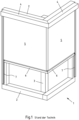
- FIG. 1 A known device for shading corner window openings is shown schematically. Shown is a corner window 1 with a surrounding frame 2, but without glazing. For external shading systems, it is irrelevant whether the corner window is frameless or whether a vertical support profile 3 is arranged in the corner area, as shown.
- the shading device consists primarily of two mitred box elements 4 arranged outside the upper frame 2, in each of which a curtain 5 is wound. Below the curtains 5, two end strips 6 can be seen, of which the end facing away from the corner is guided in the area of the frame 2 by a guide rail 7, and the end strips are connected in the corner area of the device by a (in Fig. 1 (not visible) angle connectors.
- Fig. 1 a corner window forming a right angle.
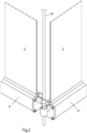
- FIG. 2 An embodiment of the device according to the invention is shown schematically. It can be clearly seen here that end strips 6" are provided, which are not arranged in a common horizontal plane. The exact structure is therefore clearer from the Fig. 3 can be found.
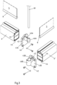
- Fig. 3 clearly shows that the ends of the 6" end strips are straight.
- the extruded profiles of the 6" end strips are designed so that they can be fitted with connecting elements without a plug-in part.
- the connecting elements are designed here as cover caps 41A and 41B, which cover the open end of the 6" end strips and are connected to them by means of screws 43 guided through corresponding openings 42 in corresponding channels 44 the end strips 6" are screwed together, so that a firm connection is created between the end strip 6" and the respective cover cap 41A or 41B. It can be seen that at the lower ends of the curtains 5 there is a fastening loop with a piping 8, which is arranged in a recess of the respective end strip 6".
- Each cover cap 41A, 41B has a protruding web 45A, 45B, at the end of which a guide element 46A, 46B is provided, each of which is provided with an inner through-opening serving as a vertical centering axis.
- a guide element 46A, 46B is provided, each of which is provided with an inner through-opening serving as a vertical centering axis.
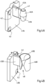
- the two cover caps 41A and 41B are Figures 4A and 4B shown again individually.
- Fig. 4A clearly shows that the guide element 46A of the cover cap 41A is significantly smaller than the guide element 46B at the end of the web 45B of the cover cap 41B.
- the guide element 46A initially has a cylindrical inner opening 47 for receiving a guide means.
- the outer shape of the guide element 46A is double-conical, with a largest outer diameter 49A visible in the vertical direction in the center of the guide element 46A.
- the larger guide element 46B also has a substantially hollow cylindrical shape, but the inner surface of this guide element 46B is again double-conical, so that a smallest inner diameter 49B is obtained there in the vertical direction.
- the special feature of this embodiment of the invention is that the two cover caps 41A and 41B are able to allow the end strips 6" connected to them to move vertically relative to each other without hindering each other.
- the larger guide element 46B has a vertical slot 48, which is dimensioned to allow the passage of the web 45A of the cover cap 41A. If both end strips 6" are arranged in a common horizontal plane, the two guide sleeves 46A and 46B act exactly like the coupling elements of the end pieces of the EP3 957 815 described embodiments, because both cover caps 41A and 41B are connected to each other almost without play by the contact line of the circles 49 A and 49 B.
- the opening 47 of the smaller guide element 46A can serve to accommodate a guide means, for example a guide rod 48, as shown in Fig. 2 is shown.
- cover caps 41A and 41B ensures that the curtains 5 installed there can be moved independently of each other in the vertical direction. This represents a significant advantage, especially when only one of the two corner window surfaces is directly exposed to sunlight, since in this case, only this surface can be protected from direct sunlight by the individually extendable curtain 5.
Landscapes
- Engineering & Computer Science (AREA)
- Structural Engineering (AREA)
- Architecture (AREA)
- Civil Engineering (AREA)
- Curtains And Furnishings For Windows Or Doors (AREA)
- Operating, Guiding And Securing Of Roll- Type Closing Members (AREA)
- Blinds (AREA)
Description
- Dargestellt und beschrieben ist eine Vorrichtung zur Beschattung über Eck verlaufender Fenster- oder Türöffnungen, mit wenigstens zwei Kastenelementen, zwei textilen Behängen, Abschlussleisten am unteren Ende der Behänge und Führungen an den dem Eckbereich abgewandten Seiten der Behänge, wobei die Behänge jeweils in einem Kastenelement aufgewickelt sind, wobei die Kastenelemente im Winkel der vorhandenen Fenster bzw. Türen miteinander verbunden sind, wobei die Abschlussleisten im Eckbereich der Vorrichtung durch einen Winkelverbinder miteinander verbunden sind und wobei als Winkelverbinder zwei an den freien Enden der Abschlussleisten angeordnete und miteinander verbindbare Verbindungselemente vorgesehen sind. Ein Beispiel mit den entsprechenden Merkmalen der Präambel von Anspruch 1 findet sich in
WO2018/178911 A1 . - Beschattungsanlagen für Fenster- oder Türöffnungen sind aus der Praxis seit langem in vielfältiger Ausführung bekannt. Die Ansteuerung der auszufahrenden Behänge geschieht dabei bevorzugt elektrisch, wobei die Antriebe, Verkabelung etc. im Inneren der eingesetzten Kastenelemente verläuft.
- In der modernen Architektur haben sich besonders die Fenster als wichtiges Stilelement entwickelt. Heute sind für Fenster bei den Ideen für die Fassade eines Hauses in Bezug auf Form und Farbe keine Grenzen gesetzt. Die Fenster verändern das ganze Erscheinungsbild des Hauses und können jedes Gebäude modern und stilvoll aussehen lassen. Minimalistisch schlanke oder gar rahmenlosen Eckfenster erfordern einen ebenso ästhetischen wie funktionstüchtigen Sonnenschutz. Daraus ergibt sich auch der Bedarf nach einem über Eck verlaufenden Sonnenschutz.
- Im bekannten Stand der Technik gibt es unterschiedliche Lösungen. Aus der
EP 3 140 488 B1 sind zwei textile Sonnenschutzeinrichtungen, bestehend aus Kastenelement, textilem Behang, Führung und Abschlussleiste bekannt, die im Winkel der Eckfenster zueinander angeordnet sind. Jede Sonnenschutzeinrichtung hat eine seitlich senkrecht verlaufende Führung, in der die zugeordnete Abschlussleiste der Sonnenschutzeinrichtung mittels einer stirnseitiger angeordneten Endkappe geführt wird. Im Bereich der Ecke, in der sich die beiden Sonnenschutzeinrichtungen treffen, sind die Abschlussleisten auf Gehrung geschnitten und über einen Verbinder miteinander verbunden. Sie bilden somit einen starren Winkel. Dies entspricht in der Art und Weise der Ausführung der Rahmenverbindung bei Hohlkammerprofilen eines Eckfensters. Im geschlossenen Zustand ist der textile Behang über die gesamte Höhe nicht verbunden, es entsteht ein Spalt zwischen den einzelnen Behängen. - Eine weitere bekannte Konstruktion sieht eine Mittelführung vor, die in der Winkelhalbierenden der Eckfenster angeordnet ist und mit dieser verbunden ist. Eine solche Mittelführung erlaubt die Führung des textilen Behangs über die gesamte Höhe. Die Abschlussleiste der Sonnenschutzeinrichtungen ist im Bereich der Mittelführung ausgenommen und weiterhin starr miteinander verbunden.
- Eine andere Ausführung Lösung stellt die
DE 10 2017 114 920 A1 dar. Der Aufbau entspricht der schon genanntenEP 3 140 488 B1 . Die Lösung unterscheidet sich durch stirnseitig angeordnete Endkappen, die eine axiale Verstellmöglichkeit besitzen. - Ein in der Konstruktion solcher Bauteile versierter Konstrukteur entnimmt dem vorgenannten Stand der Technik,
- dass die Abschlussprofile entsprechend dem Eckfenster auf Gehrung geschnitten sind,
- dass die Sonnenschutzeinrichtung über einen einstückigen Verbinder starr entsprechend dem Eckfenster miteinander verbunden sind,
- dass die Gehrungsflächen der Abschlussprofile sich berühren und somit die Hohlkammer der Abschlussprofile verschließen,
- dass der Verbinder der Abschlussprofile erst nach erfolgter Montage der Behänge eingesetzt wird.
- Der zuvor beschriebene Stand der Technik kommt in der Praxis aus mehreren Gründen an seine Grenzen. Gemäß DIN EN 1991-4, Lastannahmen für Bauten, werden die Flächen in Innen-, Rand- und Eckbereiche eingeteilt. Für diese Bereiche ergeben sich in Abhängigkeit von der Gebäudehöhe unterschiedliche Windlasten bei Dächern und Fassaden. Betrachtet man diese Eckfenster hinsichtlich der verschiedenen Lastanforderung kommt man zu der Erkenntnis, dass im Eckbereich mit mindestens dem 4-fachen der Windlast zu rechnen ist. Hierauf wird heute mit einer entsprechenden Steuerung der Sonnenschutzeinrichtung reagiert, die dann viermal früher als bei einem Fenster in der Fläche öffnet. Dies hat wiederum zur Folge, dass Eckfenster entsprechend früher ungeschützt der Sonneneinstrahlung ausgesetzt sind.
- Eine weitere Anforderung an eine Sonnenschutzeinrichtung ist eine möglichst blendfreie Beschattung. Die heutigen Lösungen erfüllen diese Anforderung nicht, da nur die Abschlussprofile miteinander verbunden sind und entsprechend durch den Spalt zwischen den Tüchern ein Lichteinfall möglich ist. Eine weitere Gefahr dieser Ausführung ist die Möglichkeit des Hinterströmens der textilen Behänge im Eckbereich und somit eine "Segel"-Bildung. Eckfenster sind in der Regel in zwei Himmelsrichtungen ausgerichtet, beispielsweise Ost/Süd. Somit besteht durchaus die Notwendigkeit die in verschiedene Himmelsrichtungen ausgerichteten Sonnenschutzeinrichtungen unabhängig voneinander zu öffnen oder zu schließen bzw. zu positionieren.
- Der Erfindung liegt daher die Aufgabe zugrunde, die eingangs genannte und zuvor näher beschriebene Vorrichtung zur Beschattung über Eck verlaufender Fenster- oder Türöffnungen so auszugestalten und auszubilden, dass eine Verbesserung des Windlasteinflusses, der Blendfreiheit, der individuellen Steuerung je Himmelsrichtung und auch eine vereinfachte Verarbeitung und Montage erreicht werden kann.
- Diese Aufgabe wird bei der Vorrichtung zur Beschattung über Eck verlaufender Fenster- oder Türöffnungen mit den Merkmalen des Oberbegriffs von Anspruch 1 dadurch gelöst, dass jedes Verbindungselement als eine mit der jeweiligen Abschlussleiste lösbar verbindbare Abdeckkappe ausgebildet ist und dass jede Abdeckkappe einen vorstehenden Steg aufweist, an dessen Ende ein Führungselement mit einer als vertikale Zentrierachse dienenden inneren Durchgangsöffnung vorgesehen ist.
- Die Erfindung hat erkannt, dass eine Aufteilung des bekannten starren Eckverbinders in zwei einzelne Verbindungselemente eine Reihe von Vorteilen mit sich bringt. Die erfindungsgemäßen Verbindungselemente bestehen jeweils aus einem bearbeiteten Strangpressprofil mit einem oder mehreren axial verlaufenden Dreh-Zentrierungs-Verbindungspunkt/en. Dabei kann der Zuschnitt der Abschlussleisten sowohl im Winkel des Eckfensters, bevorzugt allerdings als gerader Schnitt (90°), ausgeführt werden.
- Bevorzugt sind die Führungselemente unterschiedlich groß ausgebildet und weist das größere Führungselement einen vertikalen Schlitz zum Passieren des Stegs des kleineren Führungselements auf, so dass beide Führungselemente in vertikaler Richtung relativ zueinander bewegbar sind ohne sich gegenseitig zu behindern. Der Schlitz ist zweckmäßiger Weise so ausgestaltet, dass er an seinen Enden aufgeweitet ist, um ein sicheres Einführen des passierenden Steges der anderen Abdeckkappe zu gewährleisten. Hierbei sind also die beiden als Abdeckkappen ausgeführten Verbindungselemente nicht fest miteinander verbunden, sondern sie sorgen für die vertikale Führung der Abschlussleisten im Bereich der Ecke des Fensters oder der Tür. Diese Lösung hat den besonderen Vorteil, dass sich beide Behänge unterschiedlich voneinander betätigen lassen, was bei fest miteinander verbundenen Verbindungselementen nicht möglich ist. Auf diese Weise können Fensterflächen, welche nicht direkt von der Sonneneinstrahlung betroffen sind, offen bleiben, während die über Eck befindliche der Sonne ausgesetzte Fensterfläche durch den ausgefahrenen Beschattungsbehang geschützt ist.
- Gemäß einer weiteren Ausgestaltung der Erfindung weist das größere Führungselement eine hohlzylindrische Form auf. Bevorzugt weist das größere Führungselement auch eine doppelkonische innere Oberfläche auf, die in ihrer Mitte den kleinsten Innendurchmesser aufweist. In weiterer bevorzugter Ausbildung der Erfindung weist das kleinere Führungselement eine zylindrische innere Öffnung zur Aufnahme eines Führungsmittels auf. Bevorzugt ist auch die äußere Form des kleineren Führungselements doppelkonisch ausgebildet und weist in ihrer Mitte den größten Außendurchmesser auf, um beim Passieren des größeren Führungselements eine Zentrierung beider Elemente zu bewirken. Die jeweiligen Ausbildungen als Doppelkonus sorgen dafür, dass sich bei der vertikalen Annäherung beider Führungselemente auf einfache Weise ein sauberes "Einfädeln" erreichen lässt.
- Als Führungsmittel dient gemäß bevorzugter Weiterbildung der Erfindung eine Führungsstange, vorzugsweise aus Edelstahl.
- Alternativ ist es auch möglich, als Führungsmittel einen Führungsdraht zu verwenden, welcher vorzugsweise als gespanntes Seil ausgebildet ist.
- Um, besonders bei Altbauten, kleinere Abweichungen der über Eck verlaufenden Fenster bzw. Türen von einem rechten Winkel auszugleichen, sind die Endstücke bzw. die Abdeckkappen aus einem elastischen und UV-beständigen Kunststoff hergestellt. Auf diese Weise können kleinere Winkelabweichungen durch die verwendeten Verbindungselemente bzw. Abdeckkappen problemlos ausgeglichen werden.
- Die vorliegende Erfindung wird nachfolgend anhand einer ein lediglich bevorzugtes Ausführungsbeispiel darstellenden Zeichnung näher erläutert. In der Zeichnung zeigen, jeweils in perspektivischer Darstellung,
- Fig. 1
- eine Eck-Beschattungsvorrichtung gemäß dem Stand der Technik und,
- Fig. 2 bis 4B
- ein Ausführungsbeispiel einer erfindungsgemäßen Vorrichtung.
- In
Fig. 1 ist eine bekannte Vorrichtung zur Beschattung über Eck verlaufender Fensteröffnungen in schematischer Darstellung gezeigt. Gezeigt ist ein Eckfenster 1 mit einem umlaufenden Rahmen 2, jedoch ohne Verglasung. Für die außenliegenden Beschattungsanlagen spielt es keine Rolle, ob es sich um ein rahmenloses Eckfenster handelt oder ob im Eckbereich, wie dargestellt, ein vertikales Stützprofil 3 angeordnet ist. - Die Beschattungsvorrichtung besteht zunächst und im Wesentlichen aus zwei außerhalb des oberen Rahmens 2 angeordneten und auf Gehrung zugeschnittenen Kastenelementen 4, in denen jeweils ein Behang 5 aufgewickelt ist. Unterhalb der Behänge 5 erkennt man zwei Abschlussleisten 6, von denen das der Ecke abgewandte Ende im Bereich des Rahmens 2 von jeweils einer Führungsschiene 7 geführt wird und wobei die Abschlussleisten im Eckbereich der Vorrichtung durch einen (in
Fig. 1 nicht sichtbaren) Winkelverbinder miteinander verbunden sind. Die genaue Anordnung der Kastenelemente 4 und Abschlussleisten 6 im Winkelbereich richten sich nach den jeweiligen örtlichen Gegebenheiten. Der Einfachheit zeigtFig. 1 ein einen rechten Winkel bildendes Eckfenster. - In
Fig. 2 ist ein Ausführungsbeispiel der erfindungsgemäßen Vorrichtung schematisch dargestellt. Man erkennt hier deutlich, dass Abschlussleisten 6" vorgesehen sind, welche nicht in einer gemeinsamen horizontalen Ebene angeordnet sind. Der genaue Aufbau ist daher deutlicher derFig. 3 zu entnehmen. -
Fig. 3 zeigt deutlich, dass die Enden der Abschlussleisten 6" gerade verlaufen. Dabei sind die Strangpressprofile der Abschlussleisten 6" so ausgeführt, dass sie mit Verbindungselementen ohne Einsteckteil versehen werden können. Die Verbindungselemente sind hier als Abdeckkappen 41A und 41B ausgeführt, die das offene Ende der Abschlussleisten 6" verdecken und mit diesem mittels durch entsprechende Öffnungen 42 geführte Schrauben 43 in entsprechenden Kanälen 44 der Abschlussleisten 6" verschraubt sind, so dass sich eine feste Verbindung zwischen Abschlussleiste 6" und der jeweiligen Abdeckkappe 41A bzw. 41B ergibt. Man erkennt, dass an den unteren Enden der Behänge 5 jeweils eine Befestigungsschlaufe mit einem Keder 8 vorgesehen ist, welche in einer Ausnehmung der jeweiligen Abschlussleiste 6" angeordnet ist. - Jede Abdeckkappe 41A, 41B weist dabei einen vorstehenden Steg 45A, 45B auf, an dessen Ende ein Führungselement 46A, 46B vorgesehen ist, welches jeweils mit einer als vertikale Zentrierachse dienenden inneren Durchgangsöffnung versehen ist. Auch hier ist die gezeigte Perspektive nicht ausreichend, um das Zusammenspiel zwischen den Kupplungselementen 46A und 46B zu verstehen. Daher sind die beiden Abdeckkappen 41A und 41B in den
Figuren 4A und 4B noch einmal einzeln dargestellt. -
Fig. 4A lässt deutlich erkennen, dass das Führungselement 46A der Abdeckkappe 41A deutlich kleiner ausgebildet ist als das Führungselement 46B am Ende des Stegs 45B der Abdeckkappe 41B. Das Führungselement 46A weist zunächst eine zylindrische innere Öffnung 47 zur Aufnahme eines Führungsmittels auf. Die äußere Form des Führungselements 46A ist doppelkonisch ausgebildet, wobei in vertikaler Richtung in der Mitte des Führungselements 46A ein größter Außendurchmesser 49A zu erkennen ist. - Auch das größere Führungselement 46B weist im Wesentlichen eine hohlzylindrische Form auf, wobei jedoch die innere Oberfläche dieses Führungselements 46B wiederum doppelkonisch ausgebildet ist, so dass sich dort in vertikaler Richtung ein kleinster Innendurchmesser 49B ergibt.
- Die Besonderheit bei dieser Ausführungsform der Erfindung liegt darin, dass die beiden Abdeckkappen 41A und 41B in der Lage sind, die mit ihnen verbundenen Abschlussleisten 6" in vertikaler Richtung relativ zueinander bewegen lassen, ohne sich gegenseitig zu behindern. Dazu weist das größere Führungselement 46B einen vertikalen Schlitz 48 auf, der in seinen Abmessungen so ausgeführt ist, dass er die Durchführung des Stegs 45A der Abdeckkappe 41A zulässt. Sind beide Abschlussleisten 6" in einer gemeinsamen horizontalen Ebene angeordnet, wirken die beiden Führungshülsen 46A und 46B genau wie die Kupplungselemente der Endstücke der in der Stammanmeldung
EP 3 957 815 beschriebenen Ausführungsbeispiele, denn beide Abdeckkappen 41A und 41B sind durch die Berührungslinie der Kreise 49 A und 49 B nahezu spielfrei miteinander verbunden. Dabei kann die Öffnung 47 des kleineren Führungselements 46A zur Aufnahme eines Führungsmittels dienen, beispielsweise einer Führungsstange 48, wie sie inFig. 2 dargestellt ist. - Durch die besondere Ausgestaltung der Abdeckkappen 41A und 41B wird also sichergestellt, dass sich die dort verbauten Behänge 5 unabhängig voneinander in vertikaler Richtung bewegen lassen. Dies stellt einen erheblichen Vorteil insbesondere dann dar, wenn lediglich einer der beiden über Eck verlaufenden Fensterflächen unmittelbar der Sonnenbestrahlung ausgesetzt ist, da in diesem Fall auch nur diese Fläche durch den einzeln ausfahrbaren Behang 5 vor direkter Sonneneinstrahlung geschützt werden kann.
- Weitere Vorteile der Erfindung ergeben sich aus den Unteransprüchen und dem - grundsätzlichen geteilten - Aufbau der Verbindungselemente bzw. Abdeckkappen, von dem das dargestellte Ausführungsbeispiel nur beispielhaft ist, da die vorliegende Erfindung auch weitere denkbare Ausführungen einschließt.
Claims (9)
- Vorrichtung zur Beschattung über Eck verlaufender Fenster- oder Türöffnungen, mit wenigstens zwei Kastenelementen (4), zwei textilen Behängen (5), Abschlussleisten (6") am unteren Ende der Behänge und Führungen an den dem Eckbereich abgewandten Seiten der Behänge (5), wobei die Behänge (5) jeweils in einem Kastenelement (4) aufgewickelt sind, wobei die Kastenelemente (4) im Winkel der vorhandenen Fenster bzw. Türen miteinander verbunden sind, wobei die Abschlussleisten (6") im Eckbereich der Vorrichtung durch einen Winkelverbinder miteinander verbunden sind,wobei als Winkelverbinder zwei an den freien Enden der Abschlussleisten (6") angeordnete und miteinander verbindbare Verbindungselemente vorgesehen sinddadurch gekennzeichnet, das s jedes Verbindungselement als eine mit der jeweiligen Abschlussleiste (6") lösbar verbindbare Abdeckkappe (41A, 41B) ausgebildet ist und dass jede Abdeckkappe (41A, 41B) einen vorstehenden Steg (45A, 45B) aufweist, an dessen Ende ein Führungselement (46A, 46B) mit einer als vertikale Zentrierachse dienenden inneren Durchgangsöffnung vorgesehen ist.
- Vorrichtung nach Anspruch 1,
dadurch gekennzeichnet, dass
die Führungselemente (46A, 46B) unterschiedlich groß ausgebildet sind, und dass das größere Führungselement (46B) einen vertikalen Schlitz (48) zum Passieren des Stegs (45A) des kleineren Führungselements (46A) aufweist, so dass beide Führungselemente (46A, 46B) in vertikaler Richtung relativ zueinander bewegbar sind, ohne sich gegenseitig zu behindern. - Vorrichtung nach Anspruch 2,
dadurch gekennzeichnet, dass
das größere Führungselement (46B) eine holzylindrische Form aufweist. - Vorrichtung nach Anspruch 3,
dadurch gekennzeichnet, dass
das größere Führungselement (46B) eine doppelkonische innere Oberfläche aufweist und in ihrer Mitte den kleinsten Innendurchmesser (49B) aufweist. - Vorrichtung nach einem der Ansprüche 2 bis 4,
dadurch gekennzeichnet, dass
das kleinere Führungselement (46A) eine zylindrische innere Öffnung (47) zur Aufnahme eines Führungsmittels aufweist. - Vorrichtung nach Anspruch 5,
dadurch gekennzeichnet, dass
das kleinere Führungselement (46A) eine äußere Form aufweist, die doppelkonisch ausgebildet ist, und in ihrer Mitte den größten Außendurchmesser (49A) aufweist, um beim Passieren des größeren Führungselements (46B) eine Zentrierung beider Elemente (46A und 46B) zu bewirken. - Vorrichtung nach Anspruch 5,
dadurch gekennzeichnet, dass
das Führungsmittel als Führungsstange (48), vorzugsweise aus Edelstahl, ausgebildet ist. - Vorrichtung nach Anspruch 5,
dadurch gekennzeichnet, dass
das Führungsmittel als Führungsdraht, vorzugsweise als gespanntes Seil, ausgebildet ist. - Vorrichtung nach einem der Ansprüche 1 bis 8,
dadurch gekennzeichnet, dass
die Abdeckkappen (41A, 41B) aus einem elastischen und UV-beständigen Kunststoff hergestellt sind.
Applications Claiming Priority (2)
| Application Number | Priority Date | Filing Date | Title |
|---|---|---|---|
| DE102020121302.6A DE102020121302A1 (de) | 2020-08-13 | 2020-08-13 | Vorrichtung zur Beschattung über Eck verlaufender Fenster- oder Türöffnungen |
| EP21181795.2A EP3957815B1 (de) | 2020-08-13 | 2021-06-25 | Vorrichtung zur beschattung über eck verlaufender fenster- oder türöffnungen |
Related Parent Applications (1)
| Application Number | Title | Priority Date | Filing Date |
|---|---|---|---|
| EP21181795.2A Division EP3957815B1 (de) | 2020-08-13 | 2021-06-25 | Vorrichtung zur beschattung über eck verlaufender fenster- oder türöffnungen |
Publications (4)
| Publication Number | Publication Date |
|---|---|
| EP4382719A2 EP4382719A2 (de) | 2024-06-12 |
| EP4382719A3 EP4382719A3 (de) | 2024-09-04 |
| EP4382719B1 true EP4382719B1 (de) | 2025-05-14 |
| EP4382719C0 EP4382719C0 (de) | 2025-05-14 |
Family
ID=76623979
Family Applications (2)
| Application Number | Title | Priority Date | Filing Date |
|---|---|---|---|
| EP21181795.2A Active EP3957815B1 (de) | 2020-08-13 | 2021-06-25 | Vorrichtung zur beschattung über eck verlaufender fenster- oder türöffnungen |
| EP24173227.0A Active EP4382719B1 (de) | 2020-08-13 | 2021-06-25 | Vorrichtung zur beschattung über eck verlaufender fenster- oder türöffnungen |
Family Applications Before (1)
| Application Number | Title | Priority Date | Filing Date |
|---|---|---|---|
| EP21181795.2A Active EP3957815B1 (de) | 2020-08-13 | 2021-06-25 | Vorrichtung zur beschattung über eck verlaufender fenster- oder türöffnungen |
Country Status (3)
| Country | Link |
|---|---|
| EP (2) | EP3957815B1 (de) |
| DE (2) | DE102020121302A1 (de) |
| PL (1) | PL4382719T3 (de) |
Families Citing this family (1)
| Publication number | Priority date | Publication date | Assignee | Title |
|---|---|---|---|---|
| DE102020121302A1 (de) | 2020-08-13 | 2022-02-17 | Heroal - Johann Henkenjohann Gmbh & Co. Kg | Vorrichtung zur Beschattung über Eck verlaufender Fenster- oder Türöffnungen |
Family Cites Families (7)
| Publication number | Priority date | Publication date | Assignee | Title |
|---|---|---|---|---|
| ITRN20020004A1 (it) | 2002-01-31 | 2003-07-31 | L M Dei F Lli Monticelli S R L | Squadra per connessione strutturale, di profilati tubolari metallici contenuti per rinforzo internamente a profilati tubolari plastici e rel |
| US8235086B2 (en) | 2009-09-14 | 2012-08-07 | Smith Richard C | System, method and apparatus for area screen coverage |
| AU2015351969A1 (en) | 2014-11-25 | 2017-04-27 | Renson Sunprotection-Screens Nv | Screen device |
| BE1022724B1 (nl) | 2015-02-18 | 2016-08-23 | Renson Sunprotection Screens Nv. | Scherminrichting |
| BE1025101B1 (nl) | 2017-03-31 | 2018-10-30 | Renson Sunprotection Screens Nv | Scherminrichting |
| DE102017114920A1 (de) | 2017-07-04 | 2019-01-10 | Warema Renkhoff Se | Eckverbund von zwei Sonnenschutzanlagen |
| DE102020121302A1 (de) | 2020-08-13 | 2022-02-17 | Heroal - Johann Henkenjohann Gmbh & Co. Kg | Vorrichtung zur Beschattung über Eck verlaufender Fenster- oder Türöffnungen |
-
2020
- 2020-08-13 DE DE102020121302.6A patent/DE102020121302A1/de active Granted
-
2021
- 2021-06-25 DE DE202021004251.2U patent/DE202021004251U1/de active Active
- 2021-06-25 EP EP21181795.2A patent/EP3957815B1/de active Active
- 2021-06-25 EP EP24173227.0A patent/EP4382719B1/de active Active
- 2021-06-25 PL PL24173227.0T patent/PL4382719T3/pl unknown
Also Published As
| Publication number | Publication date |
|---|---|
| EP4382719A3 (de) | 2024-09-04 |
| DE202021004251U1 (de) | 2023-04-03 |
| EP3957815B1 (de) | 2024-05-22 |
| DE102020121302A1 (de) | 2022-02-17 |
| PL4382719T3 (pl) | 2025-09-01 |
| EP3957815A1 (de) | 2022-02-23 |
| EP4382719A2 (de) | 2024-06-12 |
| EP4382719C0 (de) | 2025-05-14 |
Similar Documents
| Publication | Publication Date | Title |
|---|---|---|
| DE69807438T2 (de) | Universelle befestigungs- und parallelführungsvorrichtung für eine fensterabschirmung | |
| EP3540172B1 (de) | Vorsatzschalenanordnung für ein verbundfenster sowie damit ausgebildetes verbundfenster | |
| DE10236648A1 (de) | Schnellaufendes Industrietor mit flexiblem Behang | |
| EP4382719A2 (de) | Vorrichtung zur beschattung über eck verlaufender fenster- oder türöffnungen | |
| DE3048333C2 (de) | Halterungsvorrichtung für ein Springrollo | |
| DE202006009738U1 (de) | Führungsanordnung für einen Querriegel eines Abschattungsmittels | |
| EP3173569B1 (de) | Schutzvorrichtung | |
| EP2708693A1 (de) | Schiebeflügelrahmen | |
| DE4428740C2 (de) | Duschabtrennung | |
| DE102006005610A1 (de) | Insektenschutzrahmen | |
| DE3305028A1 (de) | Dauerlueftung fuer fensterrahmen oder -fluegel, fenster-blendrahmen oder waende von gebaeuden | |
| EP4474610B1 (de) | Schutzvorrichtung für eine gebäudeöffnung und gebäudeöffnung mit einer solchen schutzvorrichtung | |
| AT516524B1 (de) | Insektenschutzsystem | |
| DE19928613A1 (de) | Abschlußstab zur Aufnahme eines Randbereiches eines Behangs zum zumindest teilweisen Abdecken einer Öffnung | |
| DE202013102830U1 (de) | Führungsschiene | |
| DE10050176B4 (de) | Einrastbare Führungsschiene | |
| EP0669446A2 (de) | System zur Aufnahme eines auf- und abwickelbaren Vorhangs, sowie Lagerkörper und Gehäuse für ein solches System | |
| AT520136B1 (de) | DAS SYSTEM DER AUßENJALOUSIE MIT INSEKTENSCHUTZ FÜR EINBAU IN DEN RAHMEN VORHANDENER FENSTER ODER TÜREN UND DAS DAMIT VERBUNDENE VERFAHREN | |
| EP4474611A1 (de) | Gebäudeöffnung mit einer schutzvorrichtung | |
| DE10049426A1 (de) | Rolloanordnung, insbesondere für ein Kraftfahrzeug-Seitenfenster | |
| DE202007000458U1 (de) | Sichtschutz-Aufsatz für Türen und diesen enthaltende Türen | |
| DE202019106733U1 (de) | Führungsprofil für ein Fenster oder eine Tür mit einem Rollladenkasten | |
| DE102013012016A1 (de) | Rollladen für eine Gebäudeöffnung | |
| DE3220138A1 (de) | Vorrichtung zum fuehren eines rolladenpanzers grosser breite | |
| DE19709478A1 (de) | Lamellenjalousie |
Legal Events
| Date | Code | Title | Description |
|---|---|---|---|
| PUAI | Public reference made under article 153(3) epc to a published international application that has entered the european phase |
Free format text: ORIGINAL CODE: 0009012 |
|
| STAA | Information on the status of an ep patent application or granted ep patent |
Free format text: STATUS: THE APPLICATION HAS BEEN PUBLISHED |
|
| AC | Divisional application: reference to earlier application |
Ref document number: 3957815 Country of ref document: EP Kind code of ref document: P |
|
| AK | Designated contracting states |
Kind code of ref document: A2 Designated state(s): AL AT BE BG CH CY CZ DE DK EE ES FI FR GB GR HR HU IE IS IT LI LT LU LV MC MK MT NL NO PL PT RO RS SE SI SK SM TR |
|
| REG | Reference to a national code |
Ref country code: DE Ref legal event code: R079 Free format text: PREVIOUS MAIN CLASS: E06B0009560000 Ipc: E06B0009080000 Ref document number: 502021007498 Country of ref document: DE |
|
| PUAL | Search report despatched |
Free format text: ORIGINAL CODE: 0009013 |
|
| P01 | Opt-out of the competence of the unified patent court (upc) registered |
Free format text: CASE NUMBER: APP_41326/2024 Effective date: 20240712 |
|
| AK | Designated contracting states |
Kind code of ref document: A3 Designated state(s): AL AT BE BG CH CY CZ DE DK EE ES FI FR GB GR HR HU IE IS IT LI LT LU LV MC MK MT NL NO PL PT RO RS SE SI SK SM TR |
|
| RIC1 | Information provided on ipc code assigned before grant |
Ipc: E06B 9/56 20060101ALI20240731BHEP Ipc: E06B 9/42 20060101ALI20240731BHEP Ipc: E06B 9/40 20060101ALI20240731BHEP Ipc: E06B 9/24 20060101ALI20240731BHEP Ipc: E06B 9/08 20060101AFI20240731BHEP |
|
| STAA | Information on the status of an ep patent application or granted ep patent |
Free format text: STATUS: REQUEST FOR EXAMINATION WAS MADE |
|
| 17P | Request for examination filed |
Effective date: 20241009 |
|
| RBV | Designated contracting states (corrected) |
Designated state(s): AL AT BE BG CH CY CZ DE DK EE ES FI FR GB GR HR HU IE IS IT LI LT LU LV MC MK MT NL NO PL PT RO RS SE SI SK SM TR |
|
| GRAP | Despatch of communication of intention to grant a patent |
Free format text: ORIGINAL CODE: EPIDOSNIGR1 |
|
| STAA | Information on the status of an ep patent application or granted ep patent |
Free format text: STATUS: GRANT OF PATENT IS INTENDED |
|
| RIC1 | Information provided on ipc code assigned before grant |
Ipc: E06B 9/56 20060101ALI20241127BHEP Ipc: E06B 9/42 20060101ALI20241127BHEP Ipc: E06B 9/40 20060101ALI20241127BHEP Ipc: E06B 9/24 20060101ALI20241127BHEP Ipc: E06B 9/08 20060101AFI20241127BHEP |
|
| INTG | Intention to grant announced |
Effective date: 20241209 |
|
| GRAS | Grant fee paid |
Free format text: ORIGINAL CODE: EPIDOSNIGR3 |
|
| GRAA | (expected) grant |
Free format text: ORIGINAL CODE: 0009210 |
|
| STAA | Information on the status of an ep patent application or granted ep patent |
Free format text: STATUS: THE PATENT HAS BEEN GRANTED |
|
| AC | Divisional application: reference to earlier application |
Ref document number: 3957815 Country of ref document: EP Kind code of ref document: P |
|
| AK | Designated contracting states |
Kind code of ref document: B1 Designated state(s): AL AT BE BG CH CY CZ DE DK EE ES FI FR GB GR HR HU IE IS IT LI LT LU LV MC MK MT NL NO PL PT RO RS SE SI SK SM TR |
|
| REG | Reference to a national code |
Ref country code: GB Ref legal event code: FG4D Free format text: NOT ENGLISH |
|
| REG | Reference to a national code |
Ref country code: CH Ref legal event code: EP |
|
| REG | Reference to a national code |
Ref country code: DE Ref legal event code: R096 Ref document number: 502021007498 Country of ref document: DE |
|
| REG | Reference to a national code |
Ref country code: IE Ref legal event code: FG4D Free format text: LANGUAGE OF EP DOCUMENT: GERMAN |
|
| U01 | Request for unitary effect filed |
Effective date: 20250612 |
|
| P04 | Withdrawal of opt-out of the competence of the unified patent court (upc) registered |
Free format text: CASE NUMBER: APP_28970/2025 Effective date: 20250618 |
|
| U07 | Unitary effect registered |
Designated state(s): AT BE BG DE DK EE FI FR IT LT LU LV MT NL PT RO SE SI Effective date: 20250623 |
|
| PGFP | Annual fee paid to national office [announced via postgrant information from national office to epo] |
Ref country code: AT Payment date: 20250721 Year of fee payment: 5 |
|
| U20 | Renewal fee for the european patent with unitary effect paid |
Year of fee payment: 5 Effective date: 20250624 |
|
| PG25 | Lapsed in a contracting state [announced via postgrant information from national office to epo] |
Ref country code: ES Free format text: LAPSE BECAUSE OF FAILURE TO SUBMIT A TRANSLATION OF THE DESCRIPTION OR TO PAY THE FEE WITHIN THE PRESCRIBED TIME-LIMIT Effective date: 20250514 |
|
| PG25 | Lapsed in a contracting state [announced via postgrant information from national office to epo] |
Ref country code: GR Free format text: LAPSE BECAUSE OF FAILURE TO SUBMIT A TRANSLATION OF THE DESCRIPTION OR TO PAY THE FEE WITHIN THE PRESCRIBED TIME-LIMIT Effective date: 20250815 |
|
| PGFP | Annual fee paid to national office [announced via postgrant information from national office to epo] |
Ref country code: NO Payment date: 20250626 Year of fee payment: 5 |
|
| PGFP | Annual fee paid to national office [announced via postgrant information from national office to epo] |
Ref country code: PL Payment date: 20250627 Year of fee payment: 5 |
|
| PG25 | Lapsed in a contracting state [announced via postgrant information from national office to epo] |
Ref country code: HR Free format text: LAPSE BECAUSE OF FAILURE TO SUBMIT A TRANSLATION OF THE DESCRIPTION OR TO PAY THE FEE WITHIN THE PRESCRIBED TIME-LIMIT Effective date: 20250514 |
|
| PGFP | Annual fee paid to national office [announced via postgrant information from national office to epo] |
Ref country code: CH Payment date: 20250701 Year of fee payment: 5 |
|
| PG25 | Lapsed in a contracting state [announced via postgrant information from national office to epo] |
Ref country code: RS Free format text: LAPSE BECAUSE OF FAILURE TO SUBMIT A TRANSLATION OF THE DESCRIPTION OR TO PAY THE FEE WITHIN THE PRESCRIBED TIME-LIMIT Effective date: 20250814 |
|
| PG25 | Lapsed in a contracting state [announced via postgrant information from national office to epo] |
Ref country code: IS Free format text: LAPSE BECAUSE OF FAILURE TO SUBMIT A TRANSLATION OF THE DESCRIPTION OR TO PAY THE FEE WITHIN THE PRESCRIBED TIME-LIMIT Effective date: 20250914 |
|
| PG25 | Lapsed in a contracting state [announced via postgrant information from national office to epo] |
Ref country code: SM Free format text: LAPSE BECAUSE OF FAILURE TO SUBMIT A TRANSLATION OF THE DESCRIPTION OR TO PAY THE FEE WITHIN THE PRESCRIBED TIME-LIMIT Effective date: 20250514 |
|
| PG25 | Lapsed in a contracting state [announced via postgrant information from national office to epo] |
Ref country code: CZ Free format text: LAPSE BECAUSE OF FAILURE TO SUBMIT A TRANSLATION OF THE DESCRIPTION OR TO PAY THE FEE WITHIN THE PRESCRIBED TIME-LIMIT Effective date: 20250514 |
|
| PG25 | Lapsed in a contracting state [announced via postgrant information from national office to epo] |
Ref country code: SK Free format text: LAPSE BECAUSE OF FAILURE TO SUBMIT A TRANSLATION OF THE DESCRIPTION OR TO PAY THE FEE WITHIN THE PRESCRIBED TIME-LIMIT Effective date: 20250514 |
|
| PG25 | Lapsed in a contracting state [announced via postgrant information from national office to epo] |
Ref country code: MC Free format text: LAPSE BECAUSE OF FAILURE TO SUBMIT A TRANSLATION OF THE DESCRIPTION OR TO PAY THE FEE WITHIN THE PRESCRIBED TIME-LIMIT Effective date: 20250514 |
|
| PLBE | No opposition filed within time limit |
Free format text: ORIGINAL CODE: 0009261 |
|
| STAA | Information on the status of an ep patent application or granted ep patent |
Free format text: STATUS: NO OPPOSITION FILED WITHIN TIME LIMIT |
|
| REG | Reference to a national code |
Ref country code: CH Ref legal event code: L10 Free format text: ST27 STATUS EVENT CODE: U-0-0-L10-L00 (AS PROVIDED BY THE NATIONAL OFFICE) Effective date: 20260325 |
|
| PG25 | Lapsed in a contracting state [announced via postgrant information from national office to epo] |
Ref country code: IE Free format text: LAPSE BECAUSE OF NON-PAYMENT OF DUE FEES Effective date: 20250625 |
|
| 26N | No opposition filed |
Effective date: 20260217 |
|
| GBPC | Gb: european patent ceased through non-payment of renewal fee |
Effective date: 20250814 |