EP4382333A1 - Kraftfahrzeugtank - Google Patents
Kraftfahrzeugtank Download PDFInfo
- Publication number
- EP4382333A1 EP4382333A1 EP22211362.3A EP22211362A EP4382333A1 EP 4382333 A1 EP4382333 A1 EP 4382333A1 EP 22211362 A EP22211362 A EP 22211362A EP 4382333 A1 EP4382333 A1 EP 4382333A1
- Authority
- EP
- European Patent Office
- Prior art keywords
- tank
- main
- motor vehicle
- extraction unit
- main tank
- Prior art date
- Legal status (The legal status is an assumption and is not a legal conclusion. Google has not performed a legal analysis and makes no representation as to the accuracy of the status listed.)
- Granted
Links
Images

Classifications
-
- B—PERFORMING OPERATIONS; TRANSPORTING
- B60—VEHICLES IN GENERAL
- B60K—ARRANGEMENT OR MOUNTING OF PROPULSION UNITS OR OF TRANSMISSIONS IN VEHICLES; ARRANGEMENT OR MOUNTING OF PLURAL DIVERSE PRIME-MOVERS IN VEHICLES; AUXILIARY DRIVES FOR VEHICLES; INSTRUMENTATION OR DASHBOARDS FOR VEHICLES; ARRANGEMENTS IN CONNECTION WITH COOLING, AIR INTAKE, GAS EXHAUST OR FUEL SUPPLY OF PROPULSION UNITS IN VEHICLES
- B60K15/00—Arrangement in connection with fuel supply of combustion engines or other fuel consuming energy converters, e.g. fuel cells; Mounting or construction of fuel tanks
- B60K15/03—Fuel tanks
-
- B—PERFORMING OPERATIONS; TRANSPORTING
- B60—VEHICLES IN GENERAL
- B60K—ARRANGEMENT OR MOUNTING OF PROPULSION UNITS OR OF TRANSMISSIONS IN VEHICLES; ARRANGEMENT OR MOUNTING OF PLURAL DIVERSE PRIME-MOVERS IN VEHICLES; AUXILIARY DRIVES FOR VEHICLES; INSTRUMENTATION OR DASHBOARDS FOR VEHICLES; ARRANGEMENTS IN CONNECTION WITH COOLING, AIR INTAKE, GAS EXHAUST OR FUEL SUPPLY OF PROPULSION UNITS IN VEHICLES
- B60K15/00—Arrangement in connection with fuel supply of combustion engines or other fuel consuming energy converters, e.g. fuel cells; Mounting or construction of fuel tanks
- B60K15/03—Fuel tanks
- B60K2015/03105—Fuel tanks with supplementary interior tanks inside the fuel tank
-
- B—PERFORMING OPERATIONS; TRANSPORTING
- B60—VEHICLES IN GENERAL
- B60K—ARRANGEMENT OR MOUNTING OF PROPULSION UNITS OR OF TRANSMISSIONS IN VEHICLES; ARRANGEMENT OR MOUNTING OF PLURAL DIVERSE PRIME-MOVERS IN VEHICLES; AUXILIARY DRIVES FOR VEHICLES; INSTRUMENTATION OR DASHBOARDS FOR VEHICLES; ARRANGEMENTS IN CONNECTION WITH COOLING, AIR INTAKE, GAS EXHAUST OR FUEL SUPPLY OF PROPULSION UNITS IN VEHICLES
- B60K15/00—Arrangement in connection with fuel supply of combustion engines or other fuel consuming energy converters, e.g. fuel cells; Mounting or construction of fuel tanks
- B60K15/03—Fuel tanks
- B60K2015/03118—Multiple tanks, i.e. two or more separate tanks
-
- B—PERFORMING OPERATIONS; TRANSPORTING
- B60—VEHICLES IN GENERAL
- B60K—ARRANGEMENT OR MOUNTING OF PROPULSION UNITS OR OF TRANSMISSIONS IN VEHICLES; ARRANGEMENT OR MOUNTING OF PLURAL DIVERSE PRIME-MOVERS IN VEHICLES; AUXILIARY DRIVES FOR VEHICLES; INSTRUMENTATION OR DASHBOARDS FOR VEHICLES; ARRANGEMENTS IN CONNECTION WITH COOLING, AIR INTAKE, GAS EXHAUST OR FUEL SUPPLY OF PROPULSION UNITS IN VEHICLES
- B60K15/00—Arrangement in connection with fuel supply of combustion engines or other fuel consuming energy converters, e.g. fuel cells; Mounting or construction of fuel tanks
- B60K15/03—Fuel tanks
- B60K2015/03118—Multiple tanks, i.e. two or more separate tanks
- B60K2015/03125—Suction lines for dual tanks
-
- B—PERFORMING OPERATIONS; TRANSPORTING
- B60—VEHICLES IN GENERAL
- B60K—ARRANGEMENT OR MOUNTING OF PROPULSION UNITS OR OF TRANSMISSIONS IN VEHICLES; ARRANGEMENT OR MOUNTING OF PLURAL DIVERSE PRIME-MOVERS IN VEHICLES; AUXILIARY DRIVES FOR VEHICLES; INSTRUMENTATION OR DASHBOARDS FOR VEHICLES; ARRANGEMENTS IN CONNECTION WITH COOLING, AIR INTAKE, GAS EXHAUST OR FUEL SUPPLY OF PROPULSION UNITS IN VEHICLES
- B60K15/00—Arrangement in connection with fuel supply of combustion engines or other fuel consuming energy converters, e.g. fuel cells; Mounting or construction of fuel tanks
- B60K15/03—Fuel tanks
- B60K2015/03118—Multiple tanks, i.e. two or more separate tanks
- B60K2015/03131—Systems for filling dual tanks
-
- B—PERFORMING OPERATIONS; TRANSPORTING
- B60—VEHICLES IN GENERAL
- B60K—ARRANGEMENT OR MOUNTING OF PROPULSION UNITS OR OF TRANSMISSIONS IN VEHICLES; ARRANGEMENT OR MOUNTING OF PLURAL DIVERSE PRIME-MOVERS IN VEHICLES; AUXILIARY DRIVES FOR VEHICLES; INSTRUMENTATION OR DASHBOARDS FOR VEHICLES; ARRANGEMENTS IN CONNECTION WITH COOLING, AIR INTAKE, GAS EXHAUST OR FUEL SUPPLY OF PROPULSION UNITS IN VEHICLES
- B60K15/00—Arrangement in connection with fuel supply of combustion engines or other fuel consuming energy converters, e.g. fuel cells; Mounting or construction of fuel tanks
- B60K15/03—Fuel tanks
- B60K2015/03118—Multiple tanks, i.e. two or more separate tanks
- B60K2015/03144—Fluid connections between the tanks
-
- B—PERFORMING OPERATIONS; TRANSPORTING
- B60—VEHICLES IN GENERAL
- B60K—ARRANGEMENT OR MOUNTING OF PROPULSION UNITS OR OF TRANSMISSIONS IN VEHICLES; ARRANGEMENT OR MOUNTING OF PLURAL DIVERSE PRIME-MOVERS IN VEHICLES; AUXILIARY DRIVES FOR VEHICLES; INSTRUMENTATION OR DASHBOARDS FOR VEHICLES; ARRANGEMENTS IN CONNECTION WITH COOLING, AIR INTAKE, GAS EXHAUST OR FUEL SUPPLY OF PROPULSION UNITS IN VEHICLES
- B60K15/00—Arrangement in connection with fuel supply of combustion engines or other fuel consuming energy converters, e.g. fuel cells; Mounting or construction of fuel tanks
- B60K15/03—Fuel tanks
- B60K2015/0321—Fuel tanks characterised by special sensors, the mounting thereof
- B60K2015/03217—Fuel level sensors
-
- B—PERFORMING OPERATIONS; TRANSPORTING
- B60—VEHICLES IN GENERAL
- B60K—ARRANGEMENT OR MOUNTING OF PROPULSION UNITS OR OF TRANSMISSIONS IN VEHICLES; ARRANGEMENT OR MOUNTING OF PLURAL DIVERSE PRIME-MOVERS IN VEHICLES; AUXILIARY DRIVES FOR VEHICLES; INSTRUMENTATION OR DASHBOARDS FOR VEHICLES; ARRANGEMENTS IN CONNECTION WITH COOLING, AIR INTAKE, GAS EXHAUST OR FUEL SUPPLY OF PROPULSION UNITS IN VEHICLES
- B60K15/00—Arrangement in connection with fuel supply of combustion engines or other fuel consuming energy converters, e.g. fuel cells; Mounting or construction of fuel tanks
- B60K15/03—Fuel tanks
- B60K2015/03328—Arrangements or special measures related to fuel tanks or fuel handling
- B60K2015/0344—Arrangements or special measures related to fuel tanks or fuel handling comprising baffles
Definitions
- the present invention relates to a motor vehicle tank comprising a main tank.
- Motor vehicles that run on fuel use a motor vehicle tank to carry the required fuel, in particular a petrol or diesel tank.
- a motor vehicle tank to carry the required fuel, in particular a petrol or diesel tank.
- Such fuel tanks are built in relatively large dimensions, particularly for commercial vehicles such as trucks, in order to be able to carry larger quantities of fuel.
- a motor vehicle tank comprising a main tank, the main tank comprising at least one main extraction unit, the main extraction unit comprising a main flow line for extracting fuel from the main tank, the motor vehicle tank comprising a secondary tank arranged laterally on the main tank and tightly connected to the main tank, the secondary tank comprising a secondary extraction unit, the secondary extraction unit comprising a secondary flow line for extracting fuel from the secondary tank, the secondary tank comprising a filler neck for directly refueling the secondary tank, the secondary tank being separated from the main tank by a partition, the partition being designed as a wall without an opening in a lower section in the installed position, and the partition having at least one opening in an upper section, above the lower section, to form an overflow between the secondary tank and the main tank.
- a side section of a motor vehicle tank is thus designed as a secondary tank.
- the secondary tank is joined to the main tank by tight welding, tight gluing or the like.
- the partition wall which has no opening only in a lower area and thus forms the secondary tank reservoir in which fuel is collected that is not delivered to the main tank.
- the secondary tank reservoir which is usually constantly filled during operation, does not extend over the entire height of the motor vehicle tank, but only up to an upper edge of the secondary tank, which is formed by the lower limit of an opening or a lowest opening in the partition wall.
- the opening, or openings, form at least one overflow into the main tank.
- the partition wall can also take on the function of a baffle from this upper edge of the secondary tank and thus form a baffle.
- the secondary tank is used to fill the entire fuel tank.
- the fuel can overflow into the main tank during refueling through the opening or openings in the upper part of the partition.
- Fuel can be drawn directly from the main tank as well as directly from the secondary tank.
- the main feed line is used to draw fuel directly from the main tank.
- the secondary feed line is used to draw fuel directly from the secondary tank.
- the partition wall is designed completely without openings in its lower area. It also preferably has no valves.
- the partition wall is therefore a simple wall, with an opening or openings in an upper area of the wall, and is therefore particularly cost-effective.
- This secondary tank can, for example, be attached to the main tank instead of an end cap that would otherwise be attached at this point, and can thus be used for modular retrofitting of a fuel tank with a refueling module.
- a valve is arranged at the end of the main feed line located in the main tank, which closes the main feed line when there is no fuel at the valve, in particular a float valve.
- the main feed line is closed and fuel can only be sucked out of the secondary tank.
- the main extraction unit comprises a level measurement and/or a vent.
- the main feed line and the secondary feed line are mechanically and/or fluidically connected to one another outside the outer boundary walls of the motor vehicle tank.
- the two feed lines can therefore be mechanically coupled, for example fastened to one another, and/or fluidically connected to form a common feed line, so that the common feed line is routed to a consumer of the fuel.
- the secondary extraction unit comprises a secondary return line for returning extracted fuel directly to the secondary tank.
- the arrangement of the secondary tank "sideways" to the main tank means an arrangement on an edge, i.e. on a boundary surface of the main tank, and not an arrangement inside or in the middle of the main tank.
- the motor vehicle tank preferably has the shape of a cuboid or cylinder.
- the motor vehicle tank preferably extends furthest in a longitudinal direction.
- the secondary tank is preferably arranged laterally in this longitudinal direction next to the main tank, in the manner of an end cap, or laterally in the transverse direction, normal to the longitudinal direction, i.e. laterally on the casing of the main tank.
- the main tank and/or the secondary tank and/or the partition wall are preferably made of metal, in particular steel. Partial or complete formation of these components from plastic is also possible.
- At least one baffle preferably several baffles, are arranged in the main tank in order to divide the main tank into at least two, preferably several, particularly preferably approximately equal-sized, baffle areas.
- the main tank does not comprise a filler neck for direct refueling of the main tank, so that refueling of the main tank takes place exclusively via the secondary tank.
- a simple refueling module for a fuel tank can thus be created by means of a secondary tank which has a simple partition wall with an opening or openings in an upper region of the partition wall as an outer boundary wall.
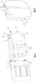
- FIG.1 and Fig.3 A motor vehicle tank according to the invention is shown.
- the Fig.2 as well as Fig. 4 and 5 show the secondary tank alone.
- the motor vehicle tank comprises a substantially cuboid-shaped main tank 1, wherein the main tank 1 comprises a main extraction unit 2, wherein the main extraction unit comprises a main feed line 2 for extracting fuel from the main tank 1.
- a valve 8 is arranged that closes the main supply line 2 when there is no fuel at the valve 8, namely a float valve.
- the main extraction unit 2 also includes a level measurement and a vent.
- main tank 1 In the main tank 1, several vertical baffles 10, each with several openings, are arranged to divide the main tank 1 into several chambers.
- the motor vehicle tank comprises a secondary tank 3 arranged laterally on the main tank 1 and welded tightly to the main tank 1.
- the secondary tank 3 comprises a filler neck 5 for the direct refueling of the secondary tank 3 and for the indirect refueling of the main tank 1.
- the main tank 1 does not have its own filler neck for the direct refueling of the main tank 1, so that the main tank 1 is refueled exclusively via the secondary tank 3 and the opening 7 in the partition wall 6.
- the partition wall 6 is designed as a simple wall without an opening in a lower section in the installed position. In an upper section, above the lower section, the partition wall 6 has at least one opening 7 or several openings 7 in order to form an overflow between the secondary tank 3 and the main tank 1.
- the secondary tank 3 comprises a secondary extraction unit, wherein the secondary extraction unit comprises a secondary feed line 4 for extracting fuel from the secondary tank 3 and a secondary return line 9 for returning extracted fuel to the secondary tank 3.
- the main feed line 2 and the secondary feed line 4 are fluidically connected to one another (not shown in the figures) outside the outer boundary walls of the motor vehicle tank by leading into a common feed line.
- the main tank 1, the secondary tank 3 and the partition 6 are made of metal.
- the required initial filling quantity can be reduced, whereby the initial filling quantity can be varied using the hole pattern of the partition.
- Improved removal in certain driving situations, such as leaning, uphill and downhill driving when using the fuel tank at an end customer is also possible, as well as a real increase in the range of the vehicle, since the switching points of the extraction unit can be designed more efficiently.
Landscapes
- Engineering & Computer Science (AREA)
- Life Sciences & Earth Sciences (AREA)
- Sustainable Development (AREA)
- Sustainable Energy (AREA)
- Chemical & Material Sciences (AREA)
- Combustion & Propulsion (AREA)
- Transportation (AREA)
- Mechanical Engineering (AREA)
- Cooling, Air Intake And Gas Exhaust, And Fuel Tank Arrangements In Propulsion Units (AREA)
Abstract
Description
- Die vorliegende Erfindung betrifft einen Kraftfahrzeugtank, umfassend einen Haupttank.
- Mit Kraftstoff betriebene Kraftfahrzeuge verwenden einen Kraftfahrzeugtank zum Mitführen des benötigten Kraftstoffs, insbesondere einen Benzin- oder Dieseltank. Derartige Kraftstofftanks werden insbesondere für Nutzfahrzeuge wie Lastkraftwagen in relativ großen Dimensionen gebaut, um größere Mengen an Kraftstoff mitführen zu können.
- Bei einer Erstbetankung, nach Herstellung eines Kraftfahrzeuges, werden üblicherweise nur geringe Kraftstoffmengen in einen Kraftfahrzeugtank gefüllt. Da sich der Kraftstoff im gesamten Kraftstofftank verteilt, der insbesondere bei Tanks für Lastkraftwagen entsprechend groß sein kann und auch eine komplexe Form aufweisen kann, ist die Nutzung der geringen Erstbetankungsmenge in einem solchen Kraftfahrzeugtank schwierig.
- Es ist eine Aufgabe der Erfindung, Kraftfahrzeugtanks in dieser Hinsicht zu verbessern und insbesondere einen kostengünstigen Kraftfahrzeugtank anzugeben, der mit einer geringen Erstbetankungsmenge an Kraftstoff betankt werden kann, die dennoch zuverlässig entnommen und genutzt werden kann.
- Die Lösung der Aufgabe erfolgt durch einen Kraftfahrzeugtank, umfassend einen Haupttank, wobei der Haupttank zumindest eine Haupt-Entnahmeeinheit umfasst, wobei die Haupt-Entnahmeeinheit eine Haupt-Vorlaufleitung umfasst zur Entnahme von Kraftstoff aus dem Haupttank, wobei der Kraftfahrzeugtank einen seitlich am Haupttank angeordneten, mit dem Haupttank dicht gefügten Nebentank umfasst, wobei der Nebentank eine Neben-Entnahmeeinheit umfasst, wobei die Neben-Entnahmeeinheit eine Neben-Vorlaufleitung umfasst zur Entnahme von Kraftstoff aus dem Nebentank, wobei der Nebentank einen Füllstutzen umfasst zur unmittelbaren Betankung des Nebentanks, wobei der Nebentank durch eine Trennwand vom Haupttank getrennt ist, wobei die Trennwand in einem in Einbaulage unteren Abschnitt als Wand ohne Öffnung ausgebildet ist und wobei die Trennwand in einem oberen Abschnitt, oberhalb des unteren Abschnitts, zumindest eine Öffnung aufweist um einen Überlauf zwischen Nebentank und Haupttank zu bilden.
- Erfindungsgemäß wird somit ein seitlicher Abschnitt eines Kraftfahrzeugtanks als Nebentank ausgebildet. Der Nebentank ist durch dichte Verschweißung, dichte Verklebung oder ähnliches mit dem Haupttank gefügt. Zwischen Haupttank und Nebentank befindet sich die Trennwand, die lediglich in einem unteren Bereich keine Öffnung aufweist und somit das Nebentankreservoir ausbildet, in dem Kraftstoff gesammelt wird, der nicht an den Haupttank abgegeben wird. Das üblicherweise im Betrieb ständig gefüllte Reservoir des Nebentanks erstreckt sich nicht über die gesamte Höhe des Kraftfahrzeugtanks, sondern lediglich bis zu einer Oberkante des Nebentanks, die durch die Untergrenze einer Öffnung oder einer untersten Öffnung in der Trennwand gebildet wird. Die Öffnung, oder Öffnungen, bilden zumindest einen Überlauf in den Haupttank. Die Trennwand kann ab dieser Oberkante des Nebentanks auch die Funktion einer Schwallwand übernehmen und somit eine Schwallwand bilden.
- Der Nebentank dient der Betankung des gesamten Kraftstofftanks. Durch die Öffnung oder Öffnungen im oberen Bereich der Trennwand kann der Kraftstoff bei Betankung in den Haupttank überfließen. Eine Entnahme von Kraftstoff ist sowohl unmittelbar aus dem Haupttank, als auch unmittelbar aus dem Nebentank möglich. Die Haupt-Vorlaufleitung dient zur Entnahme von Kraftstoff unmittelbar aus dem Haupttank. Die Neben-Vorlaufleitung dient zur Entnahme von Kraftstoff unmittelbar aus dem Nebentank
- Die Trennwand ist in ihrem unteren Bereich vollständig ohne Öffnungen ausgebildet. Sie weist bevorzugt auch keine Ventile auf. Die Trennwand ist daher eine einfache Wand, mit Öffnung oder Öffnungen in einem oberen Bereich der Wand, und ist daher besonders kostengünstig. Die Trennwand bildet zusammen mit äußeren Begrenzungswänden des Nebentanks, den Nebentank aus. Dieser Nebentank kann beispielsweise anstatt einer sonst an dieser Stelle befestigbaren Endkappe auf den Haupttank aufgebracht werden und kann somit einer modulartigen Nachrüstung eines Kraftstofftanks mit einem Betankungsmodul dienen.
- Es kann somit eine kostengünstige und robuste Integration eines Betankungsmoduls bei gleichzeitiger Steigerung der reellen Reichweite insbesondere bei Nutzfahrzeugtanks erreicht werden.
- Weitere Vorteile einer erfindungsgemäßen Lösung können sein:
Es ist kein zusätzlicher Behälter im Tank zur Bildung des Nebentanks erforderlich und die damit verbundenen Fixierelemente entfallen. Ein robusteres Design entsteht dadurch. Es kommt zu einer Reduktion der Ausfallwahrscheinlichkeit im Betrieb aufgrund Reduktion der bestehenden Komponenten und Verwendung bewährter, einfacher Komponenten. Es sind keine neuen Schnittstellen erforderlich. Es ist keine besondere Lösung für Servicebarkeit/Wartung des Nebentanks erforderlich.
Ein gewünschter Füllstand des Nebentanks nach Erstbetankung kann flexibel realisiert werden durch Wahl der Position der Öffnung oder Öffnungen bzw. des Lochbildes an der Trennwand. Eine Kombination von einem Tank im Tank (Metall oder Kunststoff ist nicht erforderlich. Es können geringere Investitionskosten erforderlich sein, durch Verwendung von bestehenden Prozessen und Komponenten zur Fertigung des Kraftfahrzeugtanks. Betankung ist über Ersatzkanister möglich, da nur der Nebentank befüllt und die Kraftstoffversorgung wieder hergestellt werden kann. Üblicherweise ist eine Kanisterbetankung über den Haupttank unzureichend, aufgrund der Verteilung des Kraftstoffs im größeren Haupttank. - Weiterbildungen der Erfindung sind in den abhängigen Ansprüchen, der Beschreibung sowie den beigefügten Zeichnungen angegeben.
- Vorzugsweise ist an dem im Haupttank befindlichen Ende der Haupt-Vorlaufleitung ein Ventil angeordnet, dass die Haupt-Vorlaufleitung schließt, wenn kein Kraftstoff am Ventil vorhanden ist, insbesondere ein Schwimmerventil. In diesem Fall ist somit die Haupt-Vorlaufleitung geschlossen und Kraftstoff kann ausschließlich aus dem Nebentank abgesaugt werden.
- Bevorzugt umfasst die Haupt-Entnahmeeinheit eine Füllstandsmessung und/oder eine Entlüftung.
- Bevorzugt sind die Haupt-Vorlaufleitung und die Neben-Vorlaufleitung außerhalb der äußeren Begrenzungswände des Kraftfahrzeugtanks mechanisch und/oder fluidleitend miteinander verbunden. Die beiden Vorlaufleitungen können also mechanisch gekoppelt sein, zum Beispiel aneinander befestigt, und/oder auch zu einer gemeinsamen Vorlaufleitung fluidleitend verbunden sein, so dass die gemeinsamen Vorlaufleitung zu einem Verbraucher des Kraftstoffs geführt ist.
- Vorzugsweise umfasst die Neben-Entnahmeeinheit eine Neben-Rücklaufleitung, zur Rückführung von entnommenem Kraftstoff, unmittelbar in den Nebentank.
- Die Anordnung des Nebentanks "seitlich" am Haupttank, bedeutet eine Anordnung an einem Rand, also an einer Begrenzungsfläche des Haupttanks, also keine Anordnung innen oder mittig im Haupttank.
- Der Kraftfahrzeugtank weist bevorzugt die Form eines Quaders oder Zylinders auf. Der Kraftfahrzeugtank erstreckt sich bevorzugt in einer Längsrichtung am weitesten. Der Nebentank ist bevorzugt seitlich in dieser Längsrichtung neben dem Haupttank angeordnet, in der Art einer Endkappe, oder seitlich in der Querrichtung, normal auf die Längsrichtung, also seitlich am Mantel des Haupttanks. Der Haupttank und/oder der Nebentank und/oder die Trennwand bestehen bevorzugt aus Metall, insbesondere aus Stahl. Eine teilweise oder vollständige Ausbildung dieser Komponenten aus Kunststoff ist ebenso möglich.
- Bevorzugt sind im Haupttank mindestens eine Schwallwand, bevorzugt mehrere Schwallwände angeordnet, um den Haupttank in mindestens zwei, bevorzugt in mehrere, besonders bevorzugt etwa gleichgroße, Schwall-Bereiche zu unterteilen.
- Bevorzugt umfasst der Haupttank keinen Füllstutzen zur unmittelbaren Betankung des Haupttanks, so dass eine Betankung des Haupttanks ausschließlich über den Nebentank erfolgt.
- Durch einen Nebentank, der als eine äußere Begrenzungswand eine einfache Trennwand mit Öffnung oder Öffnungen in einem oberen Bereich der Trennwand aufweist, kann somit ein einfaches Betankungsmodul für einen Kraftstofftank geschaffen werden.
- Die Erfindung wird im Folgenden beispielhaft unter Bezugnahme auf die Zeichnungen beschrieben.
- Fig. 1
- ist eine dreidimensionale Darstellung eines erfindungsgemäßen Kraftfahrzeugtanks.
- Fig. 2
- ist eine dreidimensionale Darstellung des Nebentanks eines erfindungsgemäßen Kraftfahrzeugtanks.
- Fig. 3
- ist eine Darstellung eines erfindungsgemäßen Kraftfahrzeugtanks von der Seite.
- Fig. 4
- ist eine Darstellung des Nebentanks eines erfindungsgemäßen Kraftfahrzeugtanks von innen.
- Fig. 5
- ist eine Darstellung des Nebentanks eines erfindungsgemäßen Kraftfahrzeugtanks von außen.
- In den
Fig. 1 undFig. 3 ist ein erfindungsgemäßer Kraftfahrzeugtank dargestellt. DieFig. 2 sowieFig. 4 und 5 zeigen den Nebentank alleine. - Der Kraftfahrzeugtank umfassend einen im Wesentlichen quaderförmigen Haupttank 1, wobei der Haupttank 1 eine Haupt-Entnahmeeinheit 2 umfasst, wobei die Haupt-Entnahmeeinheit eine Haupt-Vorlaufleitung 2 umfasst zur Entnahme von Kraftstoff aus dem Haupttank 1.
- An dem im Haupttank 1 befindlichen Ende der Haupt-Vorlaufleitung 2 ist ein Ventil 8 angeordnet, dass die Haupt-Vorlaufleitung 2 schließt, wenn kein Kraftstoff am Ventil 8 vorhanden ist, nämlich ein Schwimmerventil. Die Haupt-Entnahmeeinheit 2 umfasst zudem eine Füllstandsmessung und eine Entlüftung.
- Im Haupttank 1 sind mehrere vertikale Schwallwände 10 mit jeweils mehreren Öffnungen angeordnet, um den Haupttank 1 in mehrere Kammern zu teilen.
- Der Kraftfahrzeugtank umfasst einen seitlich am Haupttank 1 angeordneten, mit dem Haupttank 1 dicht verschweißten Nebentank 3.
- Der Nebentank 3 umfasst einen Füllstutzen 5 zur unmittelbaren Betankung des Nebentanks 3 und zur mittelbaren Betankung des Haupttanks 1. Der Haupttank 1 hat keinen eigenen Füllstutzen zur unmittelbaren Betankung des Haupttanks 1, so dass eine Betankung des Haupttanks 1 ausschließlich über den Nebentank 3 und die Öffnung 7 in der Trennwand 6 erfolgt.
- Der Nebentank 3 ist durch eine Trennwand 6 vom Haupttank 1 getrennt. Der Nebentank 3 ist im Bereich der Trennwand 6 mit dem Haupttank 1 durch außen am Kraftfahrzeugtank umlaufende Schweißnähte dicht verschweißt.
- Die Trennwand 6 ist in einem in Einbaulage unteren Abschnitt als einfache Wand ohne Öffnung ausgebildet. In einem oberen Abschnitt, oberhalb des unteren Abschnitts, weist die Trennwand 6 zumindest eine Öffnung 7 oder auch mehrere Öffnungen 7 auf, um einen Überlauf zwischen Nebentank 3 und Haupttank 1 zu bilden.
- Der Nebentank 3 umfasst eine Neben-Entnahmeeinheit, wobei die Neben-Entnahmeeinheit eine Neben-Vorlaufleitung 4 umfasst zur Entnahme von Kraftstoff aus dem Nebentank 3 und eine Neben-Rücklaufleitung 9 zur Rückführung von entnommenem Kraftstoff in den Nebentank 3. Die Haupt-Vorlaufleitung 2 und die Neben-Vorlaufleitung 4 sind (in den Fig. nicht dargestellt) außerhalb der äußeren Begrenzungswände des Kraftfahrzeugtanks fluidleitend miteinander verbunden, indem sie in eine gemeinsame Vorlaufleitung führen.
- Der Haupttank 1, der Nebentank 3 und die Trennwand 6 bestehen aus Metall.
- Durch die Verwendung eines Nebentanks, der durch eine Kombination aus Schwallwand und Trennwand von einem Haupttank getrennt ist, kann die erforderliche Erstbefüllmenge reduziert werden, wobei die Erstbefüllmenge variabel über das Lochbild der Trennwand gestaltbar ist. Eine verbesserte Entnahme bei bestimmten Fahrsituationen, wie Schräglage, Berg- und Talfahrt bei Verwendung des Kraftstofftanks bei einem Endkunden ist ebenso möglich, sowie eine reelle Steigerung der Reichweite des Kraftfahrzeugs, da die Schaltpunkte der Entnahmeeinheit effizienter gestaltet werden können.
-
- 1
- Haupttank
- 2
- Haupt-Vorlaufleitung
- 3
- Nebentank
- 4
- Neben-Vorlaufleitung
- 5
- Füllstutzen
- 6
- Trennwand
- 7
- Öffnung
- 8
- Ventil
- 9
- Neben-Rücklaufleitung
- 10
- Schwallwand
Claims (9)
- Kraftfahrzeugtank, umfassend einen Haupttank (1), wobei der Haupttank (1) zumindest eine Haupt-Entnahmeeinheit (2) umfasst, wobei die Haupt-Entnahmeeinheit eine Haupt-Vorlaufleitung (2) umfasst zur Entnahme von Kraftstoff aus dem Haupttank,
dadurch gekennzeichnet, dass der Kraftfahrzeugtank einen seitlich am Haupttank (1) angeordneten, mit dem Haupttank (1) dicht gefügten Nebentank (3) umfasst, wobei der Nebentank (3) eine Neben-Entnahmeeinheit umfasst, wobei die Neben-Entnahmeeinheit eine Neben-Vorlaufleitung (4) umfasst zur Entnahme von Kraftstoff aus dem Nebentank (3), wobei der Nebentank (3) einen Füllstutzen (5) umfasst zur unmittelbaren Betankung des Nebentanks (3), wobei der Nebentank (3) durch eine Trennwand (6) vom Haupttank (1) getrennt ist, wobei die Trennwand (6) in einem in Einbaulage unteren Abschnitt als Wand ohne Öffnung ausgebildet ist und wobei die Trennwand in einem oberen Abschnitt, oberhalb des unteren Abschnitts, zumindest eine Öffnung (7) aufweist, um einen Überlauf zwischen Nebentank (3) und Haupttank (1) zu bilden. - Kraftfahrzeugtank nach Anspruch 1,
dadurch gekennzeichnet, dass an dem im Haupttank (1) befindlichen Ende der Haupt-Vorlaufleitung (2) ein Ventil (8) angeordnet ist, dass die Haupt-Vorlaufleitung (2) schließt, wenn kein Kraftstoff am Ventil (8) vorhanden ist, insbesondere ein Schwimmerventil. - Kraftfahrzeugtank nach zumindest einem der vorhergehenden Ansprüche,
dadurch gekennzeichnet , dass die Trennwand (6) in dem oberen Abschnitt, oberhalb des unteren Abschnitts, mehrere Öffnungen (7) aufweist und somit eine Schwallwand bildet. - Kraftfahrzeugtank nach zumindest einem der vorhergehenden Ansprüche,
dadurch gekennzeichnet , dass der Haupttank (1) und/oder der Nebentank (3) und/oder die Trennwand (6) aus Metall bestehen. - Kraftfahrzeugtank nach zumindest einem der vorhergehenden Ansprüche,
dadurch gekennzeichnet , dass die Haupt-Entnahmeeinheit (2) eine Füllstandsmessung und/oder eine Entlüftung umfasst. - Kraftfahrzeugtank nach zumindest einem der vorhergehenden Ansprüche,
dadurch gekennzeichnet, dass die Haupt-Vorlaufleitung (2) und die Neben-Vorlaufleitung (4) außerhalb der äußeren Begrenzungswände des Kraftfahrzeugtanks mechanisch und/oder fluidleitend miteinander verbunden sind. - Kraftfahrzeugtank nach zumindest einem der vorhergehenden Ansprüche,
dadurch gekennzeichnet, dass die Neben-Entnahmeeinheit (4) eine Neben-Rücklaufleitung (9) umfasst zur Rückführung von entnommenem Kraftstoff in den Nebentank (3). - Kraftfahrzeugtank nach zumindest einem der vorhergehenden Ansprüche,
dadurch gekennzeichnet, dass im Haupttank (1) mindestens eine Schwallwand (10), bevorzugt mehrere Schwallwände (10) angeordnet sind, um den Haupttank (1) in mindestens zwei, bevorzugt in mehrere, Bereiche zu teilen. - Kraftfahrzeugtank nach zumindest einem der vorhergehenden Ansprüche,
dadurch gekennzeichnet, dass der Haupttank (1) keinen Füllstutzen umfasst zur unmittelbaren Betankung des Haupttanks (1), so dass eine Betankung des Haupttanks (1) ausschließlich über den Nebentank (3) erfolgt.
Priority Applications (4)
| Application Number | Priority Date | Filing Date | Title |
|---|---|---|---|
| PL22211362.3T PL4382333T3 (pl) | 2022-12-05 | 2022-12-05 | Zbiornik pojazdu silnikowego |
| EP22211362.3A EP4382333B1 (de) | 2022-12-05 | 2022-12-05 | Kraftfahrzeugtank |
| US18/502,042 US20240181868A1 (en) | 2022-12-05 | 2023-11-05 | Vehicle tank |
| CN202311645298.7A CN118144549A (zh) | 2022-12-05 | 2023-12-04 | 车辆油箱 |
Applications Claiming Priority (1)
| Application Number | Priority Date | Filing Date | Title |
|---|---|---|---|
| EP22211362.3A EP4382333B1 (de) | 2022-12-05 | 2022-12-05 | Kraftfahrzeugtank |
Publications (2)
| Publication Number | Publication Date |
|---|---|
| EP4382333A1 true EP4382333A1 (de) | 2024-06-12 |
| EP4382333B1 EP4382333B1 (de) | 2025-04-09 |
Family
ID=84389003
Family Applications (1)
| Application Number | Title | Priority Date | Filing Date |
|---|---|---|---|
| EP22211362.3A Active EP4382333B1 (de) | 2022-12-05 | 2022-12-05 | Kraftfahrzeugtank |
Country Status (4)
| Country | Link |
|---|---|
| US (1) | US20240181868A1 (de) |
| EP (1) | EP4382333B1 (de) |
| CN (1) | CN118144549A (de) |
| PL (1) | PL4382333T3 (de) |
Families Citing this family (1)
| Publication number | Priority date | Publication date | Assignee | Title |
|---|---|---|---|---|
| US12434556B2 (en) * | 2023-06-15 | 2025-10-07 | MAGNA Energy Storage Systems GmbH Werk Schwäbisch Gmünd | Fuel tank with filler neck |
Citations (5)
| Publication number | Priority date | Publication date | Assignee | Title |
|---|---|---|---|---|
| DE2602234B1 (de) * | 1976-01-22 | 1977-04-28 | Opel Adam Ag | Kraftstoffbehaelter mit einem Speichertopf |
| EP0976600A2 (de) * | 1998-07-27 | 2000-02-02 | Kautex Textron GmbH & Co. KG. | Kraftstofftank |
| DE29824173U1 (de) * | 1998-08-10 | 2000-06-08 | MAN Nutzfahrzeuge AG, 80995 München | Vorrichtung zur Entlüftung mindestens eines Zusatztreibstofftanks in einem Omnibus |
| DE29824208U1 (de) * | 1998-07-27 | 2000-07-13 | Kautex Textron Gmbh & Co Kg | Kraftstofftank |
| EP2832572A1 (de) * | 2013-08-01 | 2015-02-04 | Magna Steyr Fuel Systems GesmbH | Kraftstofftank |
Family Cites Families (4)
| Publication number | Priority date | Publication date | Assignee | Title |
|---|---|---|---|---|
| US5979485A (en) * | 1996-07-01 | 1999-11-09 | Walbro Corporation | Fuel tank level equalizer system |
| US6371153B1 (en) * | 2001-03-16 | 2002-04-16 | Robert Bosch Corporation | Dual fuel delivery module system for multi-chambered or multiple automotive fuel tanks |
| SE523331C2 (sv) * | 2002-07-19 | 2004-04-13 | Volvo Lastvagnar Ab | Bränsletank |
| US10780778B1 (en) * | 2017-04-17 | 2020-09-22 | Volvo Truck Corporation | System and method for balancing fuel levels among multiple fuel tanks |
-
2022
- 2022-12-05 EP EP22211362.3A patent/EP4382333B1/de active Active
- 2022-12-05 PL PL22211362.3T patent/PL4382333T3/pl unknown
-
2023
- 2023-11-05 US US18/502,042 patent/US20240181868A1/en active Pending
- 2023-12-04 CN CN202311645298.7A patent/CN118144549A/zh active Pending
Patent Citations (5)
| Publication number | Priority date | Publication date | Assignee | Title |
|---|---|---|---|---|
| DE2602234B1 (de) * | 1976-01-22 | 1977-04-28 | Opel Adam Ag | Kraftstoffbehaelter mit einem Speichertopf |
| EP0976600A2 (de) * | 1998-07-27 | 2000-02-02 | Kautex Textron GmbH & Co. KG. | Kraftstofftank |
| DE29824208U1 (de) * | 1998-07-27 | 2000-07-13 | Kautex Textron Gmbh & Co Kg | Kraftstofftank |
| DE29824173U1 (de) * | 1998-08-10 | 2000-06-08 | MAN Nutzfahrzeuge AG, 80995 München | Vorrichtung zur Entlüftung mindestens eines Zusatztreibstofftanks in einem Omnibus |
| EP2832572A1 (de) * | 2013-08-01 | 2015-02-04 | Magna Steyr Fuel Systems GesmbH | Kraftstofftank |
Also Published As
| Publication number | Publication date |
|---|---|
| CN118144549A (zh) | 2024-06-07 |
| US20240181868A1 (en) | 2024-06-06 |
| EP4382333B1 (de) | 2025-04-09 |
| PL4382333T3 (pl) | 2025-10-20 |
Similar Documents
| Publication | Publication Date | Title |
|---|---|---|
| EP0598078B1 (de) | Kraftstofftank mit einem in diesem angeordneten behälter | |
| EP1332065B1 (de) | Kraftstofftank | |
| WO2010102616A1 (de) | Ölbehälter | |
| DE112017005062T5 (de) | Füllbegrenzungsentlüftungsventil mit hoher Absperrhöhe | |
| EP4382333B1 (de) | Kraftfahrzeugtank | |
| DE2425111A1 (de) | Entgasungsvorrichtung fuer kraftstofftanks von kraftfahrzeugen | |
| DE20019968U1 (de) | Einrichtung zur Kraftstoffversorgung eines Kfz | |
| EP1186457B1 (de) | Kraftstofftank | |
| EP2842785B1 (de) | Nutzfahrzeugtank | |
| WO2004026609A1 (de) | Kammerentleerungseinrichtung | |
| DE3115504A1 (de) | Anordnung mit mehreren treibstofftanks zur versorgung eines brennkraftmotors | |
| EP2738031B1 (de) | Tanksystem für ein Kraftfahrzeug | |
| DE3224943C2 (de) | Kraftstoffbehälteranlage für Kraftfahrzeuge, insbesondere Omnibusse | |
| EP0979747B1 (de) | Befülleinrichtung | |
| DE4102961A1 (de) | Tankanordnung fuer ein kraftfahrzeug | |
| DE2056086A1 (de) | Luftungsventil fur einen Kraftstoff tank in einem Kraftfahrzeug | |
| DE10063389A1 (de) | Lüftungs- und/oder Druckausgleichssystem für einen Kraftstoffbehälter | |
| DE3932192C2 (de) | Kraftstoffbehälter für Kraftfahrzeuge | |
| EP2628623B1 (de) | Kraftstofftankvorrichtung für ein nutzfahrzeug | |
| DE102014202361B4 (de) | Kraftstofftanksystem | |
| EP0763441B1 (de) | Vorrichtung zum Entlüften eines Kraftstoffbehälters eines Kraftfahrzeuges | |
| AT527419B1 (de) | Entgasungssystem für einen Kraftstofftank | |
| DE102019130133A1 (de) | Betriebsmittelbehälter zum Speichern eines Betriebsmittels und Kraftfahrzeug | |
| DE102019108893A1 (de) | Tankanlage für ein Kraftfahrzeug | |
| WO2023144415A1 (de) | Betriebsmittelbehälter für ein fahrzeug und fahrzeug mit betriebsmittelbehälter |
Legal Events
| Date | Code | Title | Description |
|---|---|---|---|
| PUAI | Public reference made under article 153(3) epc to a published international application that has entered the european phase |
Free format text: ORIGINAL CODE: 0009012 |
|
| STAA | Information on the status of an ep patent application or granted ep patent |
Free format text: STATUS: REQUEST FOR EXAMINATION WAS MADE |
|
| 17P | Request for examination filed |
Effective date: 20230918 |
|
| AK | Designated contracting states |
Kind code of ref document: A1 Designated state(s): AL AT BE BG CH CY CZ DE DK EE ES FI FR GB GR HR HU IE IS IT LI LT LU LV MC ME MK MT NL NO PL PT RO RS SE SI SK SM TR |
|
| GRAP | Despatch of communication of intention to grant a patent |
Free format text: ORIGINAL CODE: EPIDOSNIGR1 |
|
| STAA | Information on the status of an ep patent application or granted ep patent |
Free format text: STATUS: GRANT OF PATENT IS INTENDED |
|
| INTG | Intention to grant announced |
Effective date: 20241002 |
|
| GRAS | Grant fee paid |
Free format text: ORIGINAL CODE: EPIDOSNIGR3 |
|
| RAP1 | Party data changed (applicant data changed or rights of an application transferred) |
Owner name: MAGNA ENERGY STORAGE SYSTEMS GMBH WERKSCHWAEBISCH GMUEND |
|
| GRAA | (expected) grant |
Free format text: ORIGINAL CODE: 0009210 |
|
| STAA | Information on the status of an ep patent application or granted ep patent |
Free format text: STATUS: THE PATENT HAS BEEN GRANTED |
|
| AK | Designated contracting states |
Kind code of ref document: B1 Designated state(s): AL AT BE BG CH CY CZ DE DK EE ES FI FR GB GR HR HU IE IS IT LI LT LU LV MC ME MK MT NL NO PL PT RO RS SE SI SK SM TR |
|
| REG | Reference to a national code |
Ref country code: GB Ref legal event code: FG4D Free format text: NOT ENGLISH |
|
| REG | Reference to a national code |
Ref country code: CH Ref legal event code: EP |
|
| REG | Reference to a national code |
Ref country code: DE Ref legal event code: R096 Ref document number: 502022003502 Country of ref document: DE |
|
| REG | Reference to a national code |
Ref country code: IE Ref legal event code: FG4D Free format text: LANGUAGE OF EP DOCUMENT: GERMAN |
|
| REG | Reference to a national code |
Ref country code: SE Ref legal event code: TRGR |
|
| REG | Reference to a national code |
Ref country code: NL Ref legal event code: FP |
|
| PG25 | Lapsed in a contracting state [announced via postgrant information from national office to epo] |
Ref country code: FI Free format text: LAPSE BECAUSE OF FAILURE TO SUBMIT A TRANSLATION OF THE DESCRIPTION OR TO PAY THE FEE WITHIN THE PRESCRIBED TIME-LIMIT Effective date: 20250409 Ref country code: ES Free format text: LAPSE BECAUSE OF FAILURE TO SUBMIT A TRANSLATION OF THE DESCRIPTION OR TO PAY THE FEE WITHIN THE PRESCRIBED TIME-LIMIT Effective date: 20250409 Ref country code: PT Free format text: LAPSE BECAUSE OF FAILURE TO SUBMIT A TRANSLATION OF THE DESCRIPTION OR TO PAY THE FEE WITHIN THE PRESCRIBED TIME-LIMIT Effective date: 20250811 |
|
| REG | Reference to a national code |
Ref country code: LT Ref legal event code: MG9D |
|
| PG25 | Lapsed in a contracting state [announced via postgrant information from national office to epo] |
Ref country code: GR Free format text: LAPSE BECAUSE OF FAILURE TO SUBMIT A TRANSLATION OF THE DESCRIPTION OR TO PAY THE FEE WITHIN THE PRESCRIBED TIME-LIMIT Effective date: 20250710 Ref country code: NO Free format text: LAPSE BECAUSE OF FAILURE TO SUBMIT A TRANSLATION OF THE DESCRIPTION OR TO PAY THE FEE WITHIN THE PRESCRIBED TIME-LIMIT Effective date: 20250709 |
|
| PG25 | Lapsed in a contracting state [announced via postgrant information from national office to epo] |
Ref country code: BG Free format text: LAPSE BECAUSE OF FAILURE TO SUBMIT A TRANSLATION OF THE DESCRIPTION OR TO PAY THE FEE WITHIN THE PRESCRIBED TIME-LIMIT Effective date: 20250409 |
|
| PG25 | Lapsed in a contracting state [announced via postgrant information from national office to epo] |
Ref country code: HR Free format text: LAPSE BECAUSE OF FAILURE TO SUBMIT A TRANSLATION OF THE DESCRIPTION OR TO PAY THE FEE WITHIN THE PRESCRIBED TIME-LIMIT Effective date: 20250409 |
|
| PG25 | Lapsed in a contracting state [announced via postgrant information from national office to epo] |
Ref country code: RS Free format text: LAPSE BECAUSE OF FAILURE TO SUBMIT A TRANSLATION OF THE DESCRIPTION OR TO PAY THE FEE WITHIN THE PRESCRIBED TIME-LIMIT Effective date: 20250709 |
|
| PG25 | Lapsed in a contracting state [announced via postgrant information from national office to epo] |
Ref country code: IS Free format text: LAPSE BECAUSE OF FAILURE TO SUBMIT A TRANSLATION OF THE DESCRIPTION OR TO PAY THE FEE WITHIN THE PRESCRIBED TIME-LIMIT Effective date: 20250809 |
|
| PG25 | Lapsed in a contracting state [announced via postgrant information from national office to epo] |
Ref country code: LV Free format text: LAPSE BECAUSE OF FAILURE TO SUBMIT A TRANSLATION OF THE DESCRIPTION OR TO PAY THE FEE WITHIN THE PRESCRIBED TIME-LIMIT Effective date: 20250409 |
|
| PGFP | Annual fee paid to national office [announced via postgrant information from national office to epo] |
Ref country code: DE Payment date: 20251211 Year of fee payment: 4 |
|
| REG | Reference to a national code |
Ref country code: DE Ref legal event code: R097 Ref document number: 502022003502 Country of ref document: DE |
|
| PG25 | Lapsed in a contracting state [announced via postgrant information from national office to epo] |
Ref country code: DK Free format text: LAPSE BECAUSE OF FAILURE TO SUBMIT A TRANSLATION OF THE DESCRIPTION OR TO PAY THE FEE WITHIN THE PRESCRIBED TIME-LIMIT Effective date: 20250409 Ref country code: SM Free format text: LAPSE BECAUSE OF FAILURE TO SUBMIT A TRANSLATION OF THE DESCRIPTION OR TO PAY THE FEE WITHIN THE PRESCRIBED TIME-LIMIT Effective date: 20250409 |
|
| PGFP | Annual fee paid to national office [announced via postgrant information from national office to epo] |
Ref country code: AT Payment date: 20260113 Year of fee payment: 4 |
|
| PGFP | Annual fee paid to national office [announced via postgrant information from national office to epo] |
Ref country code: FR Payment date: 20251229 Year of fee payment: 4 Ref country code: NL Payment date: 20251219 Year of fee payment: 4 |
|
| PGFP | Annual fee paid to national office [announced via postgrant information from national office to epo] |
Ref country code: TR Payment date: 20251201 Year of fee payment: 4 |
|
| PGFP | Annual fee paid to national office [announced via postgrant information from national office to epo] |
Ref country code: SE Payment date: 20251219 Year of fee payment: 4 |
|
| PG25 | Lapsed in a contracting state [announced via postgrant information from national office to epo] |
Ref country code: CZ Free format text: LAPSE BECAUSE OF FAILURE TO SUBMIT A TRANSLATION OF THE DESCRIPTION OR TO PAY THE FEE WITHIN THE PRESCRIBED TIME-LIMIT Effective date: 20250409 |
|
| PGFP | Annual fee paid to national office [announced via postgrant information from national office to epo] |
Ref country code: PL Payment date: 20251201 Year of fee payment: 4 |
|
| PG25 | Lapsed in a contracting state [announced via postgrant information from national office to epo] |
Ref country code: EE Free format text: LAPSE BECAUSE OF FAILURE TO SUBMIT A TRANSLATION OF THE DESCRIPTION OR TO PAY THE FEE WITHIN THE PRESCRIBED TIME-LIMIT Effective date: 20250409 |
|
| PG25 | Lapsed in a contracting state [announced via postgrant information from national office to epo] |
Ref country code: SK Free format text: LAPSE BECAUSE OF FAILURE TO SUBMIT A TRANSLATION OF THE DESCRIPTION OR TO PAY THE FEE WITHIN THE PRESCRIBED TIME-LIMIT Effective date: 20250409 |
|
| PG25 | Lapsed in a contracting state [announced via postgrant information from national office to epo] |
Ref country code: IT Free format text: LAPSE BECAUSE OF FAILURE TO SUBMIT A TRANSLATION OF THE DESCRIPTION OR TO PAY THE FEE WITHIN THE PRESCRIBED TIME-LIMIT Effective date: 20250409 |
|
| PLBE | No opposition filed within time limit |
Free format text: ORIGINAL CODE: 0009261 |
|
| STAA | Information on the status of an ep patent application or granted ep patent |
Free format text: STATUS: NO OPPOSITION FILED WITHIN TIME LIMIT |
|
| REG | Reference to a national code |
Ref country code: CH Ref legal event code: L10 Free format text: ST27 STATUS EVENT CODE: U-0-0-L10-L00 (AS PROVIDED BY THE NATIONAL OFFICE) Effective date: 20260218 |
|
| PG25 | Lapsed in a contracting state [announced via postgrant information from national office to epo] |
Ref country code: RO Free format text: LAPSE BECAUSE OF FAILURE TO SUBMIT A TRANSLATION OF THE DESCRIPTION OR TO PAY THE FEE WITHIN THE PRESCRIBED TIME-LIMIT Effective date: 20250409 |
|
| 26N | No opposition filed |
Effective date: 20260112 |