EP4382220B1 - Rohrreiniger und rohrleitungsreinigungssystem - Google Patents
Rohrreiniger und rohrleitungsreinigungssystem Download PDFInfo
- Publication number
- EP4382220B1 EP4382220B1 EP23754698.1A EP23754698A EP4382220B1 EP 4382220 B1 EP4382220 B1 EP 4382220B1 EP 23754698 A EP23754698 A EP 23754698A EP 4382220 B1 EP4382220 B1 EP 4382220B1
- Authority
- EP
- European Patent Office
- Prior art keywords
- pipeline
- pipe cleaner
- cleaning
- cleaning portion
- dust particles
- Prior art date
- Legal status (The legal status is an assumption and is not a legal conclusion. Google has not performed a legal analysis and makes no representation as to the accuracy of the status listed.)
- Active
Links
Images

Classifications
-
- B—PERFORMING OPERATIONS; TRANSPORTING
- B08—CLEANING
- B08B—CLEANING IN GENERAL; PREVENTION OF FOULING IN GENERAL
- B08B1/00—Cleaning by methods involving the use of tools
- B08B1/10—Cleaning by methods involving the use of tools characterised by the type of cleaning tool
- B08B1/12—Brushes
-
- B—PERFORMING OPERATIONS; TRANSPORTING
- B08—CLEANING
- B08B—CLEANING IN GENERAL; PREVENTION OF FOULING IN GENERAL
- B08B9/00—Cleaning hollow articles by methods or apparatus specially adapted thereto
- B08B9/02—Cleaning pipes or tubes or systems of pipes or tubes
- B08B9/027—Cleaning the internal surfaces; Removal of blockages
- B08B9/04—Cleaning the internal surfaces; Removal of blockages using cleaning devices introduced into and moved along the pipes
- B08B9/043—Cleaning the internal surfaces; Removal of blockages using cleaning devices introduced into and moved along the pipes moved by externally powered mechanical linkage, e.g. pushed or drawn through the pipes
- B08B9/0436—Cleaning the internal surfaces; Removal of blockages using cleaning devices introduced into and moved along the pipes moved by externally powered mechanical linkage, e.g. pushed or drawn through the pipes provided with mechanical cleaning tools, e.g. scrapers, with or without additional fluid jets
-
- B—PERFORMING OPERATIONS; TRANSPORTING
- B08—CLEANING
- B08B—CLEANING IN GENERAL; PREVENTION OF FOULING IN GENERAL
- B08B9/00—Cleaning hollow articles by methods or apparatus specially adapted thereto
- B08B9/02—Cleaning pipes or tubes or systems of pipes or tubes
- B08B9/027—Cleaning the internal surfaces; Removal of blockages
- B08B9/04—Cleaning the internal surfaces; Removal of blockages using cleaning devices introduced into and moved along the pipes
- B08B9/053—Cleaning the internal surfaces; Removal of blockages using cleaning devices introduced into and moved along the pipes moved along the pipes by a fluid, e.g. by fluid pressure or by suction
- B08B9/055—Cleaning the internal surfaces; Removal of blockages using cleaning devices introduced into and moved along the pipes moved along the pipes by a fluid, e.g. by fluid pressure or by suction the cleaning devices conforming to, or being conformable to, substantially the same cross-section of the pipes, e.g. pigs or moles
- B08B9/0552—Spherically shaped pigs
-
- B—PERFORMING OPERATIONS; TRANSPORTING
- B08—CLEANING
- B08B—CLEANING IN GENERAL; PREVENTION OF FOULING IN GENERAL
- B08B9/00—Cleaning hollow articles by methods or apparatus specially adapted thereto
- B08B9/02—Cleaning pipes or tubes or systems of pipes or tubes
- B08B9/027—Cleaning the internal surfaces; Removal of blockages
- B08B9/04—Cleaning the internal surfaces; Removal of blockages using cleaning devices introduced into and moved along the pipes
- B08B9/053—Cleaning the internal surfaces; Removal of blockages using cleaning devices introduced into and moved along the pipes moved along the pipes by a fluid, e.g. by fluid pressure or by suction
- B08B9/055—Cleaning the internal surfaces; Removal of blockages using cleaning devices introduced into and moved along the pipes moved along the pipes by a fluid, e.g. by fluid pressure or by suction the cleaning devices conforming to, or being conformable to, substantially the same cross-section of the pipes, e.g. pigs or moles
- B08B9/0557—Pigs with rings shaped cleaning members, e.g. cup shaped pigs
-
- F—MECHANICAL ENGINEERING; LIGHTING; HEATING; WEAPONS; BLASTING
- F16—ENGINEERING ELEMENTS AND UNITS; GENERAL MEASURES FOR PRODUCING AND MAINTAINING EFFECTIVE FUNCTIONING OF MACHINES OR INSTALLATIONS; THERMAL INSULATION IN GENERAL
- F16L—PIPES; JOINTS OR FITTINGS FOR PIPES; SUPPORTS FOR PIPES, CABLES OR PROTECTIVE TUBING; MEANS FOR THERMAL INSULATION IN GENERAL
- F16L55/00—Devices or appurtenances for use in, or in connection with, pipes or pipe systems
- F16L55/26—Pigs or moles, i.e. devices movable in a pipe or conduit with or without self-contained propulsion means
- F16L55/28—Constructional aspects
Definitions
- the present application relates to the technical field of pipeline cleaning, and in particular, to a pipe cleaner and a pipeline cleaning system.
- Pipeline is a device that is coupled by pipes, pipe couplers, and valves etc. for delivering gas, liquid, or fluid with solid particles.
- US2018149301A1 describes a deformable pig comprising an outer shell having a hollow, spherical shape and a deformable core material contained within the outer shell. This document discloses the preamble of appended claim 1.
- EP1074312A1 describes a compressibly deformable pipe pig for cleaning pipelines, wherein the surface of the pipe pig is provided with a textile covering.
- KR20100137969A describes a dust removing ball of a cleaning apparatus for the inside of a ventilation duct cleans the inside duct with being transferred to a ball collector by a ball feeder.
- DE102006035258A1 describes an abrasive particle for cleaning inner walls of a pipe and/or a hose.
- JPH11179308A describes an electrically charged pig , a static eliminator pig, and a cleaning pig of an elastic body containing a cleaning liquid arranged from the upstream side to the downstream side in the direction in which the pigs are moved in a pipeline.
- US3732434A describes a pipeline pig for transporting electrical circuitry through a pipeline.
- an embodiment of the present application provides a pipe cleaner as defined in claims 1 to 11 and a pipeline cleaning system as defined in claims 12 to 14, which is capable of effectively guiding out static electricity generated by friction between the pipe cleaner and the pipe wall during the process of cleaning dust particles in the pipeline with the pipe cleaner, and effectively preventing static electricity from accumulating on the surface of the pipe cleaner and reacting with hazardous dust particles, thereby not only ensuring the cleaning effect for the pipeline, but also ensuring safety in the process of cleaning dust particles in the pipeline with the pipe cleaner, and safety accidents such as combustion and explosion are avoided.
- an embodiment of the present application provides a pipe cleaner, the pipe cleaner is applied to a to-be-cleaned pipeline, which comprises:
- the pipe cleaner according to the first aspect of the present application has at least the following beneficial effects:
- the cleaning portion is capable of pushing out dust particles in the pipeline to the tail end of the pipeline when the pipe cleaner moves in the to-be-cleaned pipeline, and at the same time, the cleaning portion is able to contact and friction with the inner wall of the pipeline so as to push down the dust particles attached to the inner wall of the pipeline, so that the dust particles attached to the inner wall of the pipeline and the dust particles in the pipeline are pushed out to the tail end of the pipeline together, thereby completing the cleaning of the pipeline.
- the cleaning portion by arranging the cleaning portion as a conductive structure, it is able to utilize the conductivity of the cleaning portion to effectively guide out the static electricity generated by friction between the cleaning portion and the pipe wall through the pipeline during the process of cleaning dust particles in the pipeline with the pipe cleaner; and effectively prevent the static electricity from being accumulated at the cleaning portion and the surface of the pipe cleaner and reacting with hazardous dust particles, thereby not only ensuring the cleaning effect for the pipeline, but also ensuring safety in the process of cleaning dust particles in the pipeline with a pipe cleaner, and safety accidents such as combustion and explosion are avoided.
- the cleaning portion is a plurality of conductive brushes arranged on the surface of the body.
- the area occupied by the cleaning portion on the surface of the body is 65% to 80% of the surface area of the body.
- the cross-sectional shape of the body is adapted to the cross-sectional shape of the pipeline.
- the body is of a spherical shape. Arranging the body in a spherical shape enables the body and the entire pipe cleaner to be adapted to a complex structure of the pipeline, and enables the pipe cleaner to clean the pipeline in a rolling manner, meanwhile, for some bended pipelines, the pipe cleaner can also change the rolling direction accordingly with the trajectory of the pipeline so as to prevent the pipe cleaner from being clogged at a corner or round transition area of the pipeline.
- the length of the cleaning portion is 15% to 20% of the diameter of the body.
- the material of the cleaning portion comprises one of carbon fiber and modified nylon.
- the material for manufacturing the cleaning portion is selected from one of carbon fiber and modified nylon, which not only ensures a good electrostatic conductivity of the cleaning portion, but also significantly reduces the weight of the cleaning portion due to the fact that the feature that the carbon fiber and modified nylon are light-weight materials, and further reduces the structural weight of the entire pipe cleaner, so as to maintains good lightness of the pipe cleaner and improve the cleaning efficiency of the pipe cleaner on dust particles in the pipeline.
- the body is configured as a conductive structure.
- the body is made as a conductor, which prevents static electricity generated by friction between the cleaning portion and the pipe wall during the process of cleaning dust particles in the pipeline with a pipe cleaner from accumulating on the surface of the body, and ensures that the body is capable of directly guiding out static electricity on the surface thereof through the pipeline, or indirectly guiding out static electricity on the surface of the body through contact between cleaning portion on the body and the pipeline, which further prevents static electricity from accumulating on the body and the cleaning portion, ensuring safety in the process of cleaning dust particles in the pipeline with a pipe cleaner, and avoiding safety accidents such as combustion and explosion.
- the interior of the body is provided with a magnetic positioning member.
- an embodiment of the present application provides a pipeline cleaning system, including: a pipeline; and the above-described pipe cleaner; wherein the pipe cleaner is movably arranged in the pipeline and is able to move along the pipeline.
- the pipeline cleaning system according to the second aspect of the present application has at least the following beneficial effects:
- the pipeline cleaning system in the present application is provided with the above described pipe cleaner, therefore, it also has the same technical effect brought by the pipe cleaner, that is, the conductivity of the cleaning portion on the surface of the pipe cleaner body can be utilized, so as to effectively guide out the static electricity generated by friction between the cleaning portion and the pipe wall through the pipeline during the process of cleaning dust particles in the pipeline with the pipe cleaner, and effectively prevent the static electricity from accumulating on the cleaning portion and the surface of the pipe cleaner and reacting with hazardous dust particles, thereby not only ensuring the cleaning effect for the pipeline, but also ensuring the safety during the process of moving the pipe cleaner along the pipeline and cleaning dust particles in the pipeline, and safety accidents such as combustion and explosion are avoided.
- the pipeline cleaning system further includes a gas delivery device, an outer wall of the pipeline is provided with a gas inlet for communicating with an outlet end of the gas delivery device, the gas delivery device is used to deliver inert gas into the pipeline to drive the pipe cleaner to move along the pipeline.
- the gas delivery device injects inert gas into the pipeline, ensuring that the pipe cleaner is driven by a driving force to move along the pipeline, so that the pipe cleaner is moved forward from the front end of the pipeline to the tail end of the pipeline, so as to push out dust particles in the pipeline and dust particles attached to the inner wall of the pipeline, thereby completing overall cleaning of the pipeline;
- the inert gas as a power source for pushing the pipe cleaner to move along the pipeline, and utilizing the feature that the inert gas does not react with other substances, chemical reaction between inert gas has and the hazardous dust particles in the pipeline is directly avoided.
- the inert gas also has an effect of making the hazardous dust particles inert to some extent, that is, inerting explosion suppression is applied to the hazardous dust particles, thereby further avoiding safety accident such as combustion and explosion.
- the inert gas is nitrogen.
- the tail end of the pipeline is connected with a dust treatment device
- the dust treatment device is capable of applying a negative pressure to the pipeline by means of pumping, and used for receiving dust particles in the pipeline and the pipe cleaner attached with dust particles.
- the dust treatment device is capable of sucking out the floating dust particles in the pipeline during the process of applying a negative pressure to the pipeline by means of pumping, thereby improving the pipeline cleaning efficiency; on the other hand, the dust treatment device also serves to receive the pipe cleaner and dust particles pushed out by the pipe cleaner, so as to recover the dust particles and the pipe cleaner.
- body 100 cleaning portion 110; magnetic positioning member 120; pipeline 200; gas inlet 210; dust treatment device 300; machining equipment 400.
- an embodiment means that a particular feature, structure, or characteristic described in connection with the embodiment can be included in at least one embodiment of the present application.
- the appearance of this phrase in various places in the specification does not necessarily refer to the same embodiment, nor is it a separate or alternative embodiment that is mutually exclusive with other embodiments. It is explicitly and implicitly understood by those skilled in the art that the embodiments described herein may be combined with other embodiments within the scope of the appended claims.
- a plurality of refers to two or more (including two).
- a plurality of groups refers to two or more (including two groups), and "a plurality of pieces” refers to two or more (including two pieces).
- a “connection” may be a fixed connection, a detachable connection, or an integrated connection; a mechanical connection or an electrical connection; a direct connection, or an indirect connection implemented through an intermediary, and may be an internal conduct of two components or an interaction of two components.
- a connection may be a fixed connection, a detachable connection, or an integrated connection; a mechanical connection or an electrical connection; a direct connection, or an indirect connection implemented through an intermediary, and may be an internal conduct of two components or an interaction of two components.
- the present application provides a pipe cleaner, the pipe cleaner is applied to a to-be-cleaned pipeline.
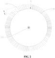
- the pipe cleaner comprises a body 100 and a cleaning portion 110, where the cleaning portion 110 is arranged on the surface of the body 100, and the cleaning portion 110 is configured as a conductive structure. Further, when the body 100 moves along the pipeline, the cleaning portion 110 is capable of pushing out dust particles in the pipeline toward the tail end of the pipeline, and guiding out static electricity generated by friction with the pipeline.
- the body 100 of the pipe cleaner may be of a spherical structure, so as to adapt to a complex structure of the pipeline, and enables the pipe cleaner to clean the pipeline in a rolling manner.
- the pipe cleaner can also change the rolling direction with the trajectory of the pipeline so as to prevent the pipe cleaner from being clogged at a corner or round transition area of the pipeline.
- the body 100 of the pipe cleaner may also be correspondingly arranged to be a regular shape adapted to the cross-sectional shape of the pipeline, such as an ellipsoid shape, a rugby ball shape, or other rotating body.
- the cleaning portion 110 when the pipe cleaner in the present application is applied in a to-be-cleaned pipeline and moves in the to-be-cleaned pipeline, the cleaning portion 110 will contact with dust particles in the pipeline, a part of the dust particles may be attached to the cleaning portion 110, and then being carried out from the pipeline by the pipe cleaner; meanwhile, when the pipe cleaner moves in the to-be-cleaned pipeline 200, the cleaning portion 110 is able to push out dust particles in the pipeline toward the tail end of the pipeline 200, thereby removing dust particles in the pipeline.
- the to-be-cleaned pipeline is a metal pipeline, and the to-be-cleaned pipeline is always in a grounded state.
- static electricity is generated due to contact and friction between the cleaning portion 110 and the inner wall of the pipeline, a part of the static electricity is directly guided out through the pipe while the other part of the static electricity is attached to the cleaning portion 110.
- the cleaning portion 110 being attached with a part of static electricity is capable of guiding out this part of static electricity in time through the contact with the inner wall of the pipeline. In this way, the static electricity generated by the friction between the cleaning portion 110 and the pipe wall is guided out through the pipeline 200 during the process of cleaning dust particles in the pipeline.
- the cleaning portion 110 is capable of pushing out dust particles in the pipeline to the tail end of the pipeline 200 when the pipe cleaner moves in the to-be-cleaned pipeline 200, and at the same time, the cleaning portion 110 is able to contact and friction with the inner wall of the pipeline 200, so as to push down the dust particles attached to the inner wall of the pipeline 200, so that the dust particles attached to the inner wall of the pipeline 200 and the dust particles in the pipeline 200 are pushed out to the tail end of the pipeline 200 together, thereby completing the cleaning of the pipeline 200.
- the cleaning portion 110 by arranging the cleaning portion 110 as a conductive structure, it is able to utilize the conductivity of the cleaning portion 110 to effectively guide out the static electricity generated by friction between the cleaning portion 110 and the pipe wall through the pipeline 200 during the process of cleaning dust particles in the pipeline with the pipe cleaner, and effectively prevent the static electricity from being accumulated at the cleaning portion 110 and the surface of the pipe cleaner and reacting with hazardous dust particles, thereby not only ensuring the cleaning effect for the pipeline, but also ensuring safety in the process of cleaning dust particles in the pipeline with a pipe cleaner, and safety accidents such as combustion and explosion are avoided.
- the cleaning portion 110 is a plurality of conductive brushes arranged on the surface of the body 100.
- the conductive brushes are integrally formed with the body 100 in a manner of being directly implanted on the surface of the body 100, and the plurality of conductive brushes are spaced and uniformly distributed along the surface contour of the body 100, and lengths of all the conductive brushes are substantially equal so as to ensure the overall structural aesthetics of the pipe cleaner.
- the material of the conductive brushes may be one of carbon fiber and modified nylon, so that the conductive brushes further have a certain elasticity.
- the conductive brushes brush off the dust particles attached to the inner wall of the pipeline and push them out to the tail end of the pipeline.
- the conductive brushes may have a slight deformation due to friction and collision with the pipe wall in order to adapt to the inner diameter of the pipeline, so as to better brush off the dust particles on the inner wall of the pipeline.
- the cleaning portion 110 is arranged to be of a conductive brush structure, on one hand, it is capable of adapting to the granular dust particles exist in the pipeline, which enables a small amount of dust particles floating in the pipeline to contact with the conductive brushes and thereby attaching to the conductive brushes during the process of pushing the dust particles in the pipeline towards the tail end of the pipeline as a whole by the pipe cleaner, and then being carried out by the pipe cleaner and removed, thereby improving the cleaning quality of the pipeline; on the other hand, by arranging the cleaning portion 110 to be of a conductive brush structure, so that the manner of frictional contact between the cleaning portion 110 and the inner wall of the pipeline is point contact, the thrust of the cleaning portion 110 on the dust particles attached to the inner wall of the pipeline is increased, thereby ensuring that the dust particles attached to the inner wall of the pipeline can be completely brushed off by the conductive brushes, avoiding remaining of the dust particles on the inner wall of the pipeline, and further improving the cleaning quality of the pipeline.
- the cleaning portion 110 is distributed along the surface contour of the body 100, and an area occupied by the cleaning portion 110 on the surface of the body 100 is 65% to 80% of the surface area of the body 100.
- the area occupied by the cleaning portion 110 on the surface of the body 100 is the sum of contact areas between the cleaning portion 110 and the surface of the body 100.
- the cleaning portion 110 is conductive brushes implanted on the surface of the body 100, and all the conductive brushes are substantially equal in length, the body 100 may be of a spherical structure. It is not difficult to understand that, in this case, the cleaning portion 110 is in a spherical shape adapt to the surface contour of the body 100, and an area of the body 100 occupied by the cleaning portion 110 on the body 100 is preferably 70% of the surface area of the body 100, that is, the surface area of the body 100 used for arranging the cleaning portion 110 in the shape of conductive brushes occupies 70% of the surface area of the body 100.
- the cross-sectional shape of the body 100 is adapted to the cross-sectional shape of the pipeline, ensuring that the shape of the body 100 effectively adapts to the cross-sectional shape of the pipeline, and ensuring that the pipe cleaner can roll or move smoothly along the pipeline, and further preventing the pipe cleaner from being clogged in the pipeline.
- the body 100 of the pipe cleaner may be correspondingly arranged to a regular shape adapted to the cross-sectional shape of the pipeline, such as sphere, an ellipsoid shape, a rugby ball shape, or other rotating body. That is, the shape of the body 100 of the pipe cleaner is specifically adapted according to the cross-sectional shape of the pipeline, so as to ensure that the pipe cleaner can roll or move smoothly along the pipeline, and further preventing the pipe cleaner from being clogged in the pipeline.
- the body 100 is in a spherical shape.
- the body 100 is in a round ball structure to enable the body 100 and the entire pipe cleaner to adapt to a complex pipeline structure, and enable the pipe cleaner to clean the pipeline in a rolling manner, meanwhile, for some bended pipelines, the pipe cleaner can also change the rolling direction accordingly with the trajectory of the pipeline so as to prevent the pipe cleaner from being clogged at a corner or round transition area of the pipeline.
- the length of the cleaning portion 110 is 15% to 20% of the diameter of the body 100.
- the body 100 is in a spherical shape, and the cleaning portion 110 are conductive brushes arranged on the surface of the body 100, all the conductive brushes have the same length.
- diameter D1 of the body 100 is 63 mm, and length L1 of the conductive brush may be 10 mm or 12 mm; in another embodiment, for example, diameter D1 of the body 100 is 89 mm, length L1 of the conductive brush may be 14 mm or 17 mm, so as to control the length of the conductive brushes to be within a suitable range, so that the length of the conductive brushes can be better adapted to the diameter of the body 100.
- the diameter of the body 100 is slightly smaller than the inner diameter of the pipeline
- the sum of the diameter of the body 100 and the length of a single conductive brush is slightly larger than the inner diameter of the pipeline
- the conductive brushes have a certain elasticity, which enables the pipe cleaner to enter the pipeline smoothly and perform cleaning to pipeline, and also enables the conductive brushes on the surface of the body 100 of the pipe cleaner to contact each part of the pipe wall, thereby realizing comprehensive cleaning of dust particles attached to the pipe wall.
- the material of the cleaning portion 110 comprises one of carbon fiber and modified nylon. That is, the cleaning portion 110 is made of carbon fiber or modified nylon.
- the carbon fiber has good conductivity and has characteristics such as high strength, friction resistance, fire resistance, and non-flammability.
- the carbon fiber material is made into the cleaning portion 110, it is ensured that the cleaning portion 110 has good conductivity and good structural strength.
- the static electricity generated by friction between the cleaning portion 110 and the pipe wall can be guided out to the pipeline in time through the cleaning portion 110, so as to prevent the static electricity from accumulating on the cleaning portion 110 and reacting with the hazardous dust particles in the pipeline, which in turn causing safety accidents such as combustion or even explosion;
- the overall structural strength of the cleaning portion 110 and the pipe cleaner is also enhanced, ensuring that the cleaning portion 110 can efficiently push out dust particles in the pipeline to the tail end of the pipeline.
- the modified nylon may be conductive nylon with high-strength, when the modified nylon material is made into the cleaning portion 110, it not only ensures the electrostatic conductivity of the cleaning portion 110 but also enables the cleaning portion 110 to have good structural strength.
- the material for manufacturing the cleaning portion 110 is selected from one of carbon fiber and modified nylon, which not only ensures a good electrostatic conductivity and structural strength of the cleaning portion 110, but also significantly reduces the weight of the cleaning portion 110 due to the fact that the carbon fiber and modified nylon are light-weight materials, and further reduces the structural weight of the entire pipe cleaner, so as to maintains good lightness of the pipe cleaner and improve the cleaning efficiency of the pipe cleaner on dust particles in the pipeline.
- the conductive material used for manufacturing the cleaning portion 110 may also be other materials with high strength, good conductivity, as well as fireproof and flame retardant properties, which is not specifically limited.
- the body 100 is configured as a conductive structure.
- the body 100 is made of conductive material, and the conductive material used to make the body 100 may be conductive carbon black or POM (polyformaldehyde resin) plastic added with carbon fiber or conductive carbon black material, which makes the body 100 has good conductivity, and at the same time also makes the body 100 has good structural strength.
- conductive carbon black or POM (polyformaldehyde resin) plastic added with carbon fiber or conductive carbon black material, which makes the body 100 has good conductivity, and at the same time also makes the body 100 has good structural strength.
- the static electricity generated by friction between the cleaning portion 110 and the pipe wall will partially attached to the void surface of the body 100.
- the body 100 is arranged as a conductive structure, that is, the body 100 is made of conductive material so that the body 100 is a conductor, which prevents static electricity generated by friction between the cleaning portion 110 and the pipe wall during the process of cleaning dust particles in the pipeline with the pipe cleaner from accumulating on the surface of the body 100, and ensures that the body 100 is capable of directly guiding out static electricity on the surface thereof through the pipeline, or indirectly guiding out static electricity on the surface of the body 100 through contact between the cleaning portion 110 on the body 100 and the pipeline, which further prevents the static electricity from accumulating on the body 100 and the cleaning portion 110, ensuring safety in the process of cleaning dust particles in the pipeline with the pipe cleaner, and avoiding safety accidents such as combustion and explosion.
- the interior of the body 100 is provided with a magnetic positioning member 120.
- the shape of the magnetic positioning member 120 is adapted to the shape of the body 100, that is, when the body 100 is in a spherical structure, the magnetic positioning member 120 is also a regular magnetic ball, and the center of the magnetic positioning member 120 coincides with the center of the body 100, so as to ensure that the gravity center of the pipe cleaner coincides with the center of thereof, thereby ensuring movement stability of the pipe cleaner in the pipeline.
- the magnetic positioning member 120 by arranging the magnetic positioning member 120 inside the body 100, it is convenient for the operator to configure a magnetic sensor that is inductively fitted with the magnetic positioning member 120 on the pipeline, so that the magnetic sensor is able to sense the position of the pipe cleaner in the pipeline, realizing real-time positioning of the pipe cleaner moving in the pipeline, and simplifying the difficulty for operators to solve blockages or other faults in the pipeline.
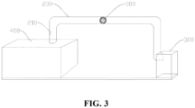
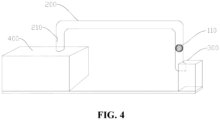
- the present application further provides a pipeline cleaning system, including a pipeline 200 and the above-described pipe cleaner, where the pipe cleaner is movably arranged in the pipeline 200 and is able to move along the pipeline 200.
- the front end of the pipeline 200 usually communicates with a machining equipment 400.
- the hazardous dust particles generated by operation of this type of machining equipment 400 are introduced into the pipeline 200.
- This type of machining equipment 400 is prone to generate hazardous dust particles, such as laser welding equipment, dryer, or pulverizer.
- the tail end of the pipeline 200 is docked with a corresponding tail end receiving device for receiving hazardous dust particles so as to perform treatment to the hazardous dust particles being pushed out from the pipe cleaner.
- the pipeline cleaning system in the present application is provided with the above described pipe cleaner, therefore, it also has the same technical effect brought by the pipe cleaner, that is, the conductivity of the cleaning portion 110 on the surface of the pipe cleaner body 100 can be utilized, so as to effectively guide out the static electricity generated by friction between the cleaning portion 110 and the pipe wall through the pipeline 200 during the process of cleaning dust particles in the pipeline with the pipe cleaner, and effectively prevent the static electricity from accumulating on the cleaning portion 110 and the surface of the pipe cleaner and reacting with hazardous dust particles, thereby not only ensuring the cleaning effect for the pipeline 200, but also ensuring the safety during the process of moving the pipe cleaner along the pipeline 200 and cleaning dust particles in the pipeline, and safety accidents such as combustion and explosion are avoided.
- the pipeline cleaning system further includes a gas delivery device (not shown in the figures), an outer wall of the pipeline 200 is provided with a gas inlet 210 for communicating an output end of the gas delivery device, and the gas delivery device is used to deliver inert gas into the pipeline 200 to drive the pipe cleaner to move along the pipeline 200.
- a gas delivery device (not shown in the figures)
- an outer wall of the pipeline 200 is provided with a gas inlet 210 for communicating an output end of the gas delivery device, and the gas delivery device is used to deliver inert gas into the pipeline 200 to drive the pipe cleaner to move along the pipeline 200.
- the inert gas used to drive the pipe cleaner rolling along the pipeline 200 has a high pressure, which allows the pipe cleaner to moves rapidly along the pipeline 200, and improves the cleaning efficiency of the pipe cleaner on the pipeline 200.
- the gas inlet 210 is disposed on an outer wall of one end of the pipeline 200 close to the machining equipment 400.
- the gas inlet 210 may be a valve, and the gas inlet 210 may also serve as an entrance for pipe cleaner.
- the gas delivery device may provide inert gas into the pipeline through the gas inlet 210, thereby pushing the pipe cleaner to move along the pipeline 200 so as to clean dust particles in the pipeline.
- the corresponding inert gas pushes the pipe cleaner to roll along the pipeline 200, thereby improving the cleaning efficiency of the pipeline 200.
- the gas delivery device injects inert gas into the pipeline 200, ensuring that the pipe cleaner is driven by a driving force to move along the pipeline 200, so that the pipe cleaner is moved forward from the front end of the pipeline to the tail end of the pipeline, so as to push out dust particles in the pipeline and dust particles attached to the inner wall of the pipeline, thereby completing overall cleaning of the pipeline;
- the inert gas as a power source for pushing the pipe cleaner to move along the pipeline, and utilizing the feature that the inert gas does not react with other substances, chemical reaction between inert gas has and the hazardous dust particles in the pipeline is directly avoided.
- the inert gas also has an effect of making the hazardous dust particles inert to some extent, that is, inerting explosion suppression is applied to the hazardous dust particles, thereby further avoiding safety accident such as combustion and explosion.
- the inert gas is nitrogen.
- the cost of nitrogen delivery device is low, so as to reduce the cost of the power source for pushing the pipe cleaner to move along the pipeline.
- the nitrogen has an effect of making the hazardous dust particles in the pipeline inert to some extent, and the safety of the process of moving the pipe cleaner along the pipeline 200 and cleaning dust particles in the pipeline is further ensured.
- a dust treatment device 300 is connected with the tail end of the pipeline 200, the dust treatment device 300 is capable of applying a negative pressure to the pipeline 200 by means of pumping, and used for receiving dust particles in the pipeline 200 and the pipe cleaner attached with dust particles.
- the front end and the tail end of the pipeline 200 are respectively connected with a machining equipment that generates dust particles and a dust treatment device 300 that receives dust particles, in this case, the pipe cleaner also moves along the pipeline to push accumulated dust particles in the pipeline into the dust treatment device 300.
- the dust treatment device 300 may be a single-piece dust remover.
- an operator may take out the pipe cleaner, and directly use the dust treatment device 300 to apply a negative pressure to the pipeline by means of pumping, so as to suck out dust particles in the pipeline, thereby achieving a cleaning and purifying effect.
- the dust treatment device 300 and the pipe cleaner may operate simultaneously to clear dust particles accumulating in the pipeline and dust particles attached to the pipe wall.
- the dust treatment device 300 is capable of sucking out dust particles floating in the pipeline during the process of applying a negative pressure to the pipeline 200 by means of pumping, thereby improving the pipeline cleaning efficiency; on the other hand, the dust treatment device 300 is further used to receive the pipe cleaner and dust particles pushed out by the pipe cleaner, so as to recover dust particles and the pipe cleaner, facilitating subsequent processing of the received dust particles.
- the dust treatment device 300 is further used to make the received dust particles inert.
- the dust treatment device 300 may be a single-piece dust remover, the dust treatment device 300 may be equipped with a powder or spray explosion suppression system according to the risk of explosion of hazardous dust, and the explosion suppression system sprays inert gas or sodium bicarbonate powder to the received dust pile, so as to avoid combustion or explosion of dust.
- the dust treatment device 300 makes the received hazardous dust particles inert in the above manner, so as to reduce the risk factor of the hazardous dust particles during subsequent processing and achieve the effect of suppressing combustion and explosion of the hazardous dust particles.
- the present application provides a pipe cleaner, the pipe cleaner is applied to a to-be-cleaned pipeline.
- the pipe cleaner comprises a body 100 and a cleaning portion 110, wherein the cleaning portion 110 is arranged on the surface of the body 100, and the cleaning portion 110 is configured as a conductive structure.
- the cleaning portion 110 is capable of pushing out dust particles in the pipeline toward the tail end of the pipeline, and guiding out static electricity generated by friction with the pipeline.
- the cleaning portion 110 provided on the surface of the body 100 as a conductive structure, it is able to utilize the conductivity of the cleaning portion 110 to effectively guide out the static electricity generated by friction between the cleaning portion 110 and the pipe wall through the pipeline 200 during the process of cleaning dust particles in the pipeline with the pipe cleaner, and effectively prevent the static electricity from being accumulated at the cleaning portion 110 and the surface of the pipe cleaner and reacting with hazardous dust particles, thereby not only ensuring the cleaning effect for the pipeline, but also ensuring safety in the process of cleaning dust particles in the pipeline with a pipe cleaner, and safety accidents such as combustion and explosion are avoided.
- the present application further provides a pipeline cleaning system.
- the pipeline cleaning system comprises a pipeline 200 and the foregoing pipe cleaner.
- the pipe cleaner is movably arranged in the pipeline 200 and is able to move along the pipeline 200.
- the pipeline cleaning system in the present application is provided with the above described pipe cleaner, therefore, it also has the same technical effect brought by the pipe cleaner, that is, the conductivity of the cleaning portion 110 on the surface of the pipe cleaner body 100 can be utilized, so as to effectively guide out the static electricity generated by friction between the cleaning portion 110 and the pipe wall through the pipeline 200 during the process of cleaning dust particles in the pipeline with the pipe cleaner, and effectively prevent the static electricity from accumulating on the cleaning portion 110 and the surface of the pipe cleaner and reacting with hazardous dust particles, thereby not only ensuring the cleaning effect for the pipeline 200, but also ensuring the safety during the process of moving the pipe cleaner along the pipeline 200 and cleaning dust particles in the pipeline, and safety accidents such as combustion and explosion are avoided.
Landscapes
- Engineering & Computer Science (AREA)
- Mechanical Engineering (AREA)
- Physics & Mathematics (AREA)
- Fluid Mechanics (AREA)
- General Engineering & Computer Science (AREA)
- Chemical & Material Sciences (AREA)
- Combustion & Propulsion (AREA)
- Cleaning In General (AREA)
Claims (14)
- Rohrreiniger zur Anwendung in einer zu reinigenden Rohrleitung (200), Folgendes umfassend:einen Körper (100), wobei die Oberfläche des Körpers (100) mit einem Reinigungsabschnitt (110) versehen ist;wobei der Reinigungsabschnitt (110) als leitfähige Struktur ausgelegt ist, wobei, wenn sich der Körper (100) entlang der Rohrleitung (200) bewegt, der Reinigungsabschnitt (110) dazu funktionsfähig ist, Staubpartikel in der Rohrleitung (200) zu einem hinteren Ende der Rohrleitung (200) herauszuschieben und durch die Reibung mit der Rohrleitung (200) erzeugte statische Elektrizität herauszuführen;wobei der Reinigungsabschnitt (110) mehrere leitfähige Borsten ist, die auf der Oberfläche des Körpers (100) angeordnet sind;dadurch gekennzeichnet, dasseine vom Reinigungsabschnitt (110) auf der Oberfläche des Körpers (100) belegte Fläche 65 % bis 80 % der Gesamtoberfläche des Körpers (100) beträgt;wobei die vom Reinigungsabschnitt (110) belegte Fläche auf der Oberfläche des Körpers (100) eine Summe von Kontaktflächen zwischen dem Reinigungsabschnitt (110) und der Oberfläche des Körpers (100) ist.
- Rohrreiniger nach Anspruch 1, wobei die Querschnittsform des Körpers (100) an die Querschnittsform der Rohrleitung (200) angepasst ist.
- Rohrreiniger nach Anspruch 2 oder 3, wobei der Körper (100) kugelförmig ist.
- Rohrreiniger nach einem der Ansprüche 1 bis 3, wobei die Länge des Reinigungsabschnitts (110) 15 % bis 20 % des Durchmessers des Körpers (100) beträgt.
- Rohrreiniger nach einem der Ansprüche 1 bis 4, wobei die mehreren leitfähigen Borsten entlang einer Oberflächenkontur des Körpers (100) beabstandet und gleichmäßig verteilt sind.
- Rohrreiniger nach einem der Ansprüche 1 bis 5, wobei der Körper (100) mit der leitfähigen Borste einstückig ausgebildet ist.
- Rohrreiniger nach einem der Ansprüche 1 bis 6, wobei der Körper (100) ellipsenförmig ist.
- Rohrreiniger nach einem der Ansprüche 1 bis 6, wobei der Körper (100) die Form eines Rugby-Balls aufweist.
- Rohrreiniger nach einem der Ansprüche 1 bis 8, wobei das Material des Reinigungsabschnitts (110) Kohlenstofffaser oder modifiziertes, elektrostatisch leitfähiges Nylon umfasst.
- Rohrreiniger nach einem der Ansprüche 1 bis 9, wobei der Körper (100) als leitfähige Struktur ausgelegt ist.
- Rohrreiniger nach einem der Ansprüche 1 bis 10, wobei das Innere des Körpers (100) mit einem magnetischen Positionierungselement (120) versehen ist.
- Rohrleitungsreinigungssystem, Folgendes umfassend:eine Rohrleitung (200) undden Rohrreiniger nach einem der Ansprüche 1 bis 11;wobei der Rohrreiniger in der Rohrleitung (200) beweglich angeordnet und dazu funktionsfähig ist, sich entlang der Rohrleitung (200) zu bewegen.
- Rohrleitungsreinigungssystem nach Anspruch 12, wobei das Rohrleitungsreinigungssystem ferner eine Gaszuführungsvorrichtung umfasst, wobei eine Außenwand der Rohrleitung (200) mit einem Gaseinlass (210) versehen ist, um mit einem Auslassende der Gaszuführungsvorrichtung zu kommunizieren, und wobei die Gaszuführungsvorrichtung dazu verwendet wird, der Rohrleitung (200) Inertgas zuzuführen, um den Rohrreiniger entlang der Rohrleitung (200) zu bewegen.
- Rohrleitungsreinigungssystem nach Anspruch 12 oder 13, wobei das hintere Ende der Rohrleitung (200) mit einer Staubbehandlungsvorrichtung (300) verbunden ist, wobei die Staubbehandlungsvorrichtung (300) dazu funktionsfähig ist, durch Pumpen einen Unterdruck auf die Rohrleitung (200) aufzubringen, und dazu verwendet wird, die Staubpartikel in der Rohrleitung (200) und den Rohrreiniger mit daran befestigten Staubpartikeln aufzunehmen.
Applications Claiming Priority (2)
| Application Number | Priority Date | Filing Date | Title |
|---|---|---|---|
| CN202222835385.6U CN218340560U (zh) | 2022-10-27 | 2022-10-27 | 清管器以及管道清洁系统 |
| PCT/CN2023/084554 WO2024087501A1 (zh) | 2022-10-27 | 2023-03-29 | 清管器以及管道清洁系统 |
Publications (3)
| Publication Number | Publication Date |
|---|---|
| EP4382220A1 EP4382220A1 (de) | 2024-06-12 |
| EP4382220A4 EP4382220A4 (de) | 2024-10-30 |
| EP4382220B1 true EP4382220B1 (de) | 2025-06-11 |
Family
ID=84898435
Family Applications (1)
| Application Number | Title | Priority Date | Filing Date |
|---|---|---|---|
| EP23754698.1A Active EP4382220B1 (de) | 2022-10-27 | 2023-03-29 | Rohrreiniger und rohrleitungsreinigungssystem |
Country Status (6)
| Country | Link |
|---|---|
| US (1) | US12434278B2 (de) |
| EP (1) | EP4382220B1 (de) |
| CN (1) | CN218340560U (de) |
| HU (1) | HUE072519T2 (de) |
| PL (1) | PL4382220T3 (de) |
| WO (1) | WO2024087501A1 (de) |
Families Citing this family (4)
| Publication number | Priority date | Publication date | Assignee | Title |
|---|---|---|---|---|
| CN218340560U (zh) * | 2022-10-27 | 2023-01-20 | 宁德时代新能源科技股份有限公司 | 清管器以及管道清洁系统 |
| CN119676938B (zh) * | 2025-02-24 | 2025-05-06 | 东莞市嘉佰达电子科技有限公司 | 一种高防护等级的锂电bms保护板 |
| CN120680649B (zh) * | 2025-05-27 | 2026-03-17 | 江苏芬茂新材料科技有限公司 | 一种用于塑料回收的颗粒清洗装置 |
| CN120885119A (zh) * | 2025-08-22 | 2025-11-04 | 甘肃省农业工程技术研究院 | 防控土壤病虫害传播的生物种衣剂复配装置及方法 |
Family Cites Families (12)
| Publication number | Priority date | Publication date | Assignee | Title |
|---|---|---|---|---|
| US3732434A (en) * | 1972-03-02 | 1973-05-08 | Trans Canada Pipelines Ltd | Pipeline pigs |
| DE3218254C1 (de) * | 1982-05-14 | 1984-01-26 | Taprogge Gesellschaft mbH, 4000 Düsseldorf | Reinigungskoerper fuer die Innenreinigung der Roehren von Roehren-Waermetauschern und Verfahren zu deren Herstellung |
| WO1995035172A2 (en) * | 1994-06-20 | 1995-12-28 | Robert Watts | Tire studded pipe pig |
| JPH11179308A (ja) * | 1997-12-24 | 1999-07-06 | Tokyo Gas Co Ltd | 既設管路のクリーニング工法 |
| DE19936016C1 (de) * | 1999-08-04 | 2000-08-03 | Waeschle Gmbh | Rohrmolch |
| US20030221273A1 (en) * | 2002-05-28 | 2003-12-04 | Phillip Mark | Method and apparatus for injection molding a plastic monolith |
| AT502209B1 (de) * | 2005-07-29 | 2008-01-15 | Semperit Ag Holding | Verfahren zur herstellung eines putzkörpers |
| KR101085895B1 (ko) * | 2009-06-24 | 2011-11-22 | 홍현성 | 환기 덕트 내부 청소장치의 먼지제거용 볼 및 이를 이용한 청소방법 |
| CN205762788U (zh) * | 2016-06-21 | 2016-12-07 | 浙江管工智能机械设备有限公司 | 一种管道清洁球 |
| US20180149301A1 (en) * | 2016-11-28 | 2018-05-31 | Naveed Aslam | Pig and pigging methods for gas pipelines |
| CN207188388U (zh) * | 2017-08-09 | 2018-04-06 | 广州纱溪机电工程技术有限公司 | 管道清洁系统 |
| CN218340560U (zh) * | 2022-10-27 | 2023-01-20 | 宁德时代新能源科技股份有限公司 | 清管器以及管道清洁系统 |
-
2022
- 2022-10-27 CN CN202222835385.6U patent/CN218340560U/zh active Active
-
2023
- 2023-03-29 PL PL23754698.1T patent/PL4382220T3/pl unknown
- 2023-03-29 EP EP23754698.1A patent/EP4382220B1/de active Active
- 2023-03-29 HU HUE23754698A patent/HUE072519T2/hu unknown
- 2023-03-29 WO PCT/CN2023/084554 patent/WO2024087501A1/zh not_active Ceased
- 2023-08-28 US US18/238,528 patent/US12434278B2/en active Active
Also Published As
| Publication number | Publication date |
|---|---|
| HUE072519T2 (hu) | 2025-11-28 |
| US12434278B2 (en) | 2025-10-07 |
| EP4382220A1 (de) | 2024-06-12 |
| EP4382220A4 (de) | 2024-10-30 |
| US20240139785A1 (en) | 2024-05-02 |
| CN218340560U (zh) | 2023-01-20 |
| WO2024087501A1 (zh) | 2024-05-02 |
| PL4382220T3 (pl) | 2025-10-06 |
Similar Documents
| Publication | Publication Date | Title |
|---|---|---|
| EP4382220B1 (de) | Rohrreiniger und rohrleitungsreinigungssystem | |
| CN102548702B (zh) | 具有带有至少一个通气口的加压焊剂递送的埋弧焊系统和焊炬以及具有通气室、套和过滤件的焊剂罩 | |
| CN203709941U (zh) | 电动吸尘器 | |
| JP4744571B2 (ja) | ピグ洗浄具及び配管のピグ洗浄方法 | |
| KR101583071B1 (ko) | 관로 표면 조도 형성장치를 무인으로 이동하는 블라스팅 대차 | |
| KR101708054B1 (ko) | 무전원 하이브리드 공압 ict 관로 청소용 대차 | |
| CN221250652U (zh) | 一种带有清理功能的自走车充电座 | |
| CN211437333U (zh) | 一种天然气管道清理装置 | |
| KR102148105B1 (ko) | 무빙 덕트 장치 및 이를 포함하는 집진 설비 | |
| JP2008179470A (ja) | 部品送出装置 | |
| JP2009279500A (ja) | 配管内清掃ノズル及び配管内清掃装置 | |
| CN210816582U (zh) | 一种用于管道内部的吸尘清洁装置 | |
| CN113000511B (zh) | 一种天然气管道清洁装置的使用方法 | |
| CN224087009U (zh) | 一种静电粉末喷枪的喷嘴机构 | |
| JPH11179308A (ja) | 既設管路のクリーニング工法 | |
| KR101127181B1 (ko) | 회전식 임펠러 블라스트 장치 | |
| CN223495417U (zh) | 运料装置和生产线系统 | |
| CN222198198U (zh) | 一种用于小管径管道的泡沫清管器 | |
| CN223445484U (zh) | 一种锅炉底部清灰设备及干熄焦系统 | |
| CN215238748U (zh) | 一种带走自动上料装置的送丝喷嘴 | |
| CN215030188U (zh) | 一种粉末输送泵 | |
| CN216460340U (zh) | 一种通信工程用导线清洁装置 | |
| CN220658000U (zh) | 一种抗氧化剂喷涂装置 | |
| CN111822476B (zh) | 一种纺织尘清除装置 | |
| KR101583249B1 (ko) | 이동형 쇼트 블라스트 장치 |
Legal Events
| Date | Code | Title | Description |
|---|---|---|---|
| STAA | Information on the status of an ep patent application or granted ep patent |
Free format text: STATUS: UNKNOWN |
|
| STAA | Information on the status of an ep patent application or granted ep patent |
Free format text: STATUS: THE INTERNATIONAL PUBLICATION HAS BEEN MADE |
|
| PUAI | Public reference made under article 153(3) epc to a published international application that has entered the european phase |
Free format text: ORIGINAL CODE: 0009012 |
|
| STAA | Information on the status of an ep patent application or granted ep patent |
Free format text: STATUS: REQUEST FOR EXAMINATION WAS MADE |
|
| 17P | Request for examination filed |
Effective date: 20230823 |
|
| AK | Designated contracting states |
Kind code of ref document: A1 Designated state(s): AL AT BE BG CH CY CZ DE DK EE ES FI FR GB GR HR HU IE IS IT LI LT LU LV MC ME MK MT NL NO PL PT RO RS SE SI SK SM TR |
|
| RAP1 | Party data changed (applicant data changed or rights of an application transferred) |
Owner name: CONTEMPORARY AMPEREX TECHNOLOGY(HONG KONG) LIMITED |
|
| A4 | Supplementary search report drawn up and despatched |
Effective date: 20240927 |
|
| RIC1 | Information provided on ipc code assigned before grant |
Ipc: B08B 9/055 20060101ALI20240924BHEP Ipc: B08B 9/043 20060101ALI20240924BHEP Ipc: B08B 1/12 20240101ALI20240924BHEP Ipc: B08B 15/04 20060101ALI20240924BHEP Ipc: B08B 9/057 20060101AFI20240924BHEP |
|
| GRAP | Despatch of communication of intention to grant a patent |
Free format text: ORIGINAL CODE: EPIDOSNIGR1 |
|
| STAA | Information on the status of an ep patent application or granted ep patent |
Free format text: STATUS: GRANT OF PATENT IS INTENDED |
|
| INTG | Intention to grant announced |
Effective date: 20250327 |
|
| GRAS | Grant fee paid |
Free format text: ORIGINAL CODE: EPIDOSNIGR3 |
|
| GRAA | (expected) grant |
Free format text: ORIGINAL CODE: 0009210 |
|
| STAA | Information on the status of an ep patent application or granted ep patent |
Free format text: STATUS: THE PATENT HAS BEEN GRANTED |
|
| AK | Designated contracting states |
Kind code of ref document: B1 Designated state(s): AL AT BE BG CH CY CZ DE DK EE ES FI FR GB GR HR HU IE IS IT LI LT LU LV MC ME MK MT NL NO PL PT RO RS SE SI SK SM TR |
|
| DAV | Request for validation of the european patent (deleted) | ||
| DAX | Request for extension of the european patent (deleted) | ||
| REG | Reference to a national code |
Ref country code: GB Ref legal event code: FG4D |
|
| REG | Reference to a national code |
Ref country code: CH Ref legal event code: EP |
|
| REG | Reference to a national code |
Ref country code: IE Ref legal event code: FG4D |
|
| REG | Reference to a national code |
Ref country code: DE Ref legal event code: R096 Ref document number: 602023003987 Country of ref document: DE |
|
| P01 | Opt-out of the competence of the unified patent court (upc) registered |
Free format text: CASE NUMBER: APP_28867/2025 Effective date: 20250617 |
|
| PG25 | Lapsed in a contracting state [announced via postgrant information from national office to epo] |
Ref country code: ES Free format text: LAPSE BECAUSE OF FAILURE TO SUBMIT A TRANSLATION OF THE DESCRIPTION OR TO PAY THE FEE WITHIN THE PRESCRIBED TIME-LIMIT Effective date: 20250611 Ref country code: FI Free format text: LAPSE BECAUSE OF FAILURE TO SUBMIT A TRANSLATION OF THE DESCRIPTION OR TO PAY THE FEE WITHIN THE PRESCRIBED TIME-LIMIT Effective date: 20250611 |
|
| REG | Reference to a national code |
Ref country code: LT Ref legal event code: MG9D |
|
| PG25 | Lapsed in a contracting state [announced via postgrant information from national office to epo] |
Ref country code: GR Free format text: LAPSE BECAUSE OF FAILURE TO SUBMIT A TRANSLATION OF THE DESCRIPTION OR TO PAY THE FEE WITHIN THE PRESCRIBED TIME-LIMIT Effective date: 20250912 Ref country code: NO Free format text: LAPSE BECAUSE OF FAILURE TO SUBMIT A TRANSLATION OF THE DESCRIPTION OR TO PAY THE FEE WITHIN THE PRESCRIBED TIME-LIMIT Effective date: 20250911 |
|
| REG | Reference to a national code |
Ref country code: NL Ref legal event code: MP Effective date: 20250611 |
|
| PG25 | Lapsed in a contracting state [announced via postgrant information from national office to epo] |
Ref country code: BG Free format text: LAPSE BECAUSE OF FAILURE TO SUBMIT A TRANSLATION OF THE DESCRIPTION OR TO PAY THE FEE WITHIN THE PRESCRIBED TIME-LIMIT Effective date: 20250611 |
|
| PG25 | Lapsed in a contracting state [announced via postgrant information from national office to epo] |
Ref country code: HR Free format text: LAPSE BECAUSE OF FAILURE TO SUBMIT A TRANSLATION OF THE DESCRIPTION OR TO PAY THE FEE WITHIN THE PRESCRIBED TIME-LIMIT Effective date: 20250611 |
|
| PG25 | Lapsed in a contracting state [announced via postgrant information from national office to epo] |
Ref country code: RS Free format text: LAPSE BECAUSE OF FAILURE TO SUBMIT A TRANSLATION OF THE DESCRIPTION OR TO PAY THE FEE WITHIN THE PRESCRIBED TIME-LIMIT Effective date: 20250911 |
|
| PG25 | Lapsed in a contracting state [announced via postgrant information from national office to epo] |
Ref country code: LV Free format text: LAPSE BECAUSE OF FAILURE TO SUBMIT A TRANSLATION OF THE DESCRIPTION OR TO PAY THE FEE WITHIN THE PRESCRIBED TIME-LIMIT Effective date: 20250611 |
|
| PG25 | Lapsed in a contracting state [announced via postgrant information from national office to epo] |
Ref country code: NL Free format text: LAPSE BECAUSE OF FAILURE TO SUBMIT A TRANSLATION OF THE DESCRIPTION OR TO PAY THE FEE WITHIN THE PRESCRIBED TIME-LIMIT Effective date: 20250611 |
|
| REG | Reference to a national code |
Ref country code: HU Ref legal event code: AG4A Ref document number: E072519 Country of ref document: HU |
|
| PG25 | Lapsed in a contracting state [announced via postgrant information from national office to epo] |
Ref country code: PT Free format text: LAPSE BECAUSE OF FAILURE TO SUBMIT A TRANSLATION OF THE DESCRIPTION OR TO PAY THE FEE WITHIN THE PRESCRIBED TIME-LIMIT Effective date: 20251013 |
|
| REG | Reference to a national code |
Ref country code: AT Ref legal event code: MK05 Ref document number: 1801972 Country of ref document: AT Kind code of ref document: T Effective date: 20250611 |
|
| PG25 | Lapsed in a contracting state [announced via postgrant information from national office to epo] |
Ref country code: IS Free format text: LAPSE BECAUSE OF FAILURE TO SUBMIT A TRANSLATION OF THE DESCRIPTION OR TO PAY THE FEE WITHIN THE PRESCRIBED TIME-LIMIT Effective date: 20251011 |
|
| PG25 | Lapsed in a contracting state [announced via postgrant information from national office to epo] |
Ref country code: AT Free format text: LAPSE BECAUSE OF FAILURE TO SUBMIT A TRANSLATION OF THE DESCRIPTION OR TO PAY THE FEE WITHIN THE PRESCRIBED TIME-LIMIT Effective date: 20250611 Ref country code: SM Free format text: LAPSE BECAUSE OF FAILURE TO SUBMIT A TRANSLATION OF THE DESCRIPTION OR TO PAY THE FEE WITHIN THE PRESCRIBED TIME-LIMIT Effective date: 20250611 |
|
| PG25 | Lapsed in a contracting state [announced via postgrant information from national office to epo] |
Ref country code: CZ Free format text: LAPSE BECAUSE OF FAILURE TO SUBMIT A TRANSLATION OF THE DESCRIPTION OR TO PAY THE FEE WITHIN THE PRESCRIBED TIME-LIMIT Effective date: 20250611 |
|
| PG25 | Lapsed in a contracting state [announced via postgrant information from national office to epo] |
Ref country code: EE Free format text: LAPSE BECAUSE OF FAILURE TO SUBMIT A TRANSLATION OF THE DESCRIPTION OR TO PAY THE FEE WITHIN THE PRESCRIBED TIME-LIMIT Effective date: 20250611 |
|
| PG25 | Lapsed in a contracting state [announced via postgrant information from national office to epo] |
Ref country code: SK Free format text: LAPSE BECAUSE OF FAILURE TO SUBMIT A TRANSLATION OF THE DESCRIPTION OR TO PAY THE FEE WITHIN THE PRESCRIBED TIME-LIMIT Effective date: 20250611 |