EP4372105A1 - Quenching device, quenching method, and metal sheet manufacturing method - Google Patents
Quenching device, quenching method, and metal sheet manufacturing method Download PDFInfo
- Publication number
- EP4372105A1 EP4372105A1 EP22861064.8A EP22861064A EP4372105A1 EP 4372105 A1 EP4372105 A1 EP 4372105A1 EP 22861064 A EP22861064 A EP 22861064A EP 4372105 A1 EP4372105 A1 EP 4372105A1
- Authority
- EP
- European Patent Office
- Prior art keywords
- metal sheet
- sheet
- cooling
- metal
- temperature
- Prior art date
- Legal status (The legal status is an assumption and is not a legal conclusion. Google has not performed a legal analysis and makes no representation as to the accuracy of the status listed.)
- Pending
Links
Images



Classifications
-
- C—CHEMISTRY; METALLURGY
- C21—METALLURGY OF IRON
- C21D—MODIFYING THE PHYSICAL STRUCTURE OF FERROUS METALS; GENERAL DEVICES FOR HEAT TREATMENT OF FERROUS OR NON-FERROUS METALS OR ALLOYS; MAKING METAL MALLEABLE, e.g. BY DECARBURISATION OR TEMPERING
- C21D9/00—Heat treatment, e.g. annealing, hardening, quenching or tempering, adapted for particular articles; Furnaces therefor
- C21D9/0062—Heat-treating apparatus with a cooling or quenching zone
-
- C—CHEMISTRY; METALLURGY
- C21—METALLURGY OF IRON
- C21D—MODIFYING THE PHYSICAL STRUCTURE OF FERROUS METALS; GENERAL DEVICES FOR HEAT TREATMENT OF FERROUS OR NON-FERROUS METALS OR ALLOYS; MAKING METAL MALLEABLE, e.g. BY DECARBURISATION OR TEMPERING
- C21D9/00—Heat treatment, e.g. annealing, hardening, quenching or tempering, adapted for particular articles; Furnaces therefor
- C21D9/52—Heat treatment, e.g. annealing, hardening, quenching or tempering, adapted for particular articles; Furnaces therefor for wires; for strips ; for rods of unlimited length
- C21D9/54—Furnaces for treating strips or wire
- C21D9/56—Continuous furnaces for strip or wire
- C21D9/573—Continuous furnaces for strip or wire with cooling
-
- B—PERFORMING OPERATIONS; TRANSPORTING
- B21—MECHANICAL METAL-WORKING WITHOUT ESSENTIALLY REMOVING MATERIAL; PUNCHING METAL
- B21B—ROLLING OF METAL
- B21B45/00—Devices for surface or other treatment of work, specially combined with or arranged in, or specially adapted for use in connection with, metal-rolling mills
- B21B45/02—Devices for surface or other treatment of work, specially combined with or arranged in, or specially adapted for use in connection with, metal-rolling mills for lubricating, cooling, or cleaning
-
- C—CHEMISTRY; METALLURGY
- C21—METALLURGY OF IRON
- C21D—MODIFYING THE PHYSICAL STRUCTURE OF FERROUS METALS; GENERAL DEVICES FOR HEAT TREATMENT OF FERROUS OR NON-FERROUS METALS OR ALLOYS; MAKING METAL MALLEABLE, e.g. BY DECARBURISATION OR TEMPERING
- C21D1/00—General methods or devices for heat treatment, e.g. annealing, hardening, quenching or tempering
- C21D1/18—Hardening; Quenching with or without subsequent tempering
-
- C—CHEMISTRY; METALLURGY
- C21—METALLURGY OF IRON
- C21D—MODIFYING THE PHYSICAL STRUCTURE OF FERROUS METALS; GENERAL DEVICES FOR HEAT TREATMENT OF FERROUS OR NON-FERROUS METALS OR ALLOYS; MAKING METAL MALLEABLE, e.g. BY DECARBURISATION OR TEMPERING
- C21D1/00—General methods or devices for heat treatment, e.g. annealing, hardening, quenching or tempering
- C21D1/56—General methods or devices for heat treatment, e.g. annealing, hardening, quenching or tempering characterised by the quenching agents
- C21D1/60—Aqueous agents
-
- C—CHEMISTRY; METALLURGY
- C21—METALLURGY OF IRON
- C21D—MODIFYING THE PHYSICAL STRUCTURE OF FERROUS METALS; GENERAL DEVICES FOR HEAT TREATMENT OF FERROUS OR NON-FERROUS METALS OR ALLOYS; MAKING METAL MALLEABLE, e.g. BY DECARBURISATION OR TEMPERING
- C21D1/00—General methods or devices for heat treatment, e.g. annealing, hardening, quenching or tempering
- C21D1/62—Quenching devices
- C21D1/63—Quenching devices for bath quenching
-
- C—CHEMISTRY; METALLURGY
- C21—METALLURGY OF IRON
- C21D—MODIFYING THE PHYSICAL STRUCTURE OF FERROUS METALS; GENERAL DEVICES FOR HEAT TREATMENT OF FERROUS OR NON-FERROUS METALS OR ALLOYS; MAKING METAL MALLEABLE, e.g. BY DECARBURISATION OR TEMPERING
- C21D1/00—General methods or devices for heat treatment, e.g. annealing, hardening, quenching or tempering
- C21D1/62—Quenching devices
- C21D1/667—Quenching devices for spray quenching
-
- C—CHEMISTRY; METALLURGY
- C21—METALLURGY OF IRON
- C21D—MODIFYING THE PHYSICAL STRUCTURE OF FERROUS METALS; GENERAL DEVICES FOR HEAT TREATMENT OF FERROUS OR NON-FERROUS METALS OR ALLOYS; MAKING METAL MALLEABLE, e.g. BY DECARBURISATION OR TEMPERING
- C21D11/00—Process control or regulation for heat treatments
- C21D11/005—Process control or regulation for heat treatments for cooling
-
- C—CHEMISTRY; METALLURGY
- C21—METALLURGY OF IRON
- C21D—MODIFYING THE PHYSICAL STRUCTURE OF FERROUS METALS; GENERAL DEVICES FOR HEAT TREATMENT OF FERROUS OR NON-FERROUS METALS OR ALLOYS; MAKING METAL MALLEABLE, e.g. BY DECARBURISATION OR TEMPERING
- C21D6/00—Heat treatment of ferrous alloys
- C21D6/005—Heat treatment of ferrous alloys containing Mn
-
- C—CHEMISTRY; METALLURGY
- C21—METALLURGY OF IRON
- C21D—MODIFYING THE PHYSICAL STRUCTURE OF FERROUS METALS; GENERAL DEVICES FOR HEAT TREATMENT OF FERROUS OR NON-FERROUS METALS OR ALLOYS; MAKING METAL MALLEABLE, e.g. BY DECARBURISATION OR TEMPERING
- C21D6/00—Heat treatment of ferrous alloys
- C21D6/008—Heat treatment of ferrous alloys containing Si
-
- C—CHEMISTRY; METALLURGY
- C21—METALLURGY OF IRON
- C21D—MODIFYING THE PHYSICAL STRUCTURE OF FERROUS METALS; GENERAL DEVICES FOR HEAT TREATMENT OF FERROUS OR NON-FERROUS METALS OR ALLOYS; MAKING METAL MALLEABLE, e.g. BY DECARBURISATION OR TEMPERING
- C21D8/00—Modifying the physical properties of ferrous metals or ferrous alloys by deformation combined with, or followed by, heat treatment
- C21D8/02—Modifying the physical properties of ferrous metals or ferrous alloys by deformation combined with, or followed by, heat treatment during manufacturing of plates or strips
- C21D8/0221—Modifying the physical properties of ferrous metals or ferrous alloys by deformation combined with, or followed by, heat treatment during manufacturing of plates or strips characterised by the working steps
- C21D8/0242—Flattening; Dressing; Flexing
-
- C—CHEMISTRY; METALLURGY
- C21—METALLURGY OF IRON
- C21D—MODIFYING THE PHYSICAL STRUCTURE OF FERROUS METALS; GENERAL DEVICES FOR HEAT TREATMENT OF FERROUS OR NON-FERROUS METALS OR ALLOYS; MAKING METAL MALLEABLE, e.g. BY DECARBURISATION OR TEMPERING
- C21D9/00—Heat treatment, e.g. annealing, hardening, quenching or tempering, adapted for particular articles; Furnaces therefor
- C21D9/46—Heat treatment, e.g. annealing, hardening, quenching or tempering, adapted for particular articles; Furnaces therefor for sheet metals
-
- C—CHEMISTRY; METALLURGY
- C21—METALLURGY OF IRON
- C21D—MODIFYING THE PHYSICAL STRUCTURE OF FERROUS METALS; GENERAL DEVICES FOR HEAT TREATMENT OF FERROUS OR NON-FERROUS METALS OR ALLOYS; MAKING METAL MALLEABLE, e.g. BY DECARBURISATION OR TEMPERING
- C21D9/00—Heat treatment, e.g. annealing, hardening, quenching or tempering, adapted for particular articles; Furnaces therefor
- C21D9/52—Heat treatment, e.g. annealing, hardening, quenching or tempering, adapted for particular articles; Furnaces therefor for wires; for strips ; for rods of unlimited length
- C21D9/54—Furnaces for treating strips or wire
- C21D9/56—Continuous furnaces for strip or wire
- C21D9/573—Continuous furnaces for strip or wire with cooling
- C21D9/5735—Details
- C21D9/5737—Rolls; Drums; Roll arrangements
-
- C—CHEMISTRY; METALLURGY
- C22—METALLURGY; FERROUS OR NON-FERROUS ALLOYS; TREATMENT OF ALLOYS OR NON-FERROUS METALS
- C22C—ALLOYS
- C22C38/00—Ferrous alloys, e.g. steel alloys
-
- C—CHEMISTRY; METALLURGY
- C21—METALLURGY OF IRON
- C21D—MODIFYING THE PHYSICAL STRUCTURE OF FERROUS METALS; GENERAL DEVICES FOR HEAT TREATMENT OF FERROUS OR NON-FERROUS METALS OR ALLOYS; MAKING METAL MALLEABLE, e.g. BY DECARBURISATION OR TEMPERING
- C21D2211/00—Microstructure comprising significant phases
- C21D2211/008—Martensite
-
- C—CHEMISTRY; METALLURGY
- C22—METALLURGY; FERROUS OR NON-FERROUS ALLOYS; TREATMENT OF ALLOYS OR NON-FERROUS METALS
- C22C—ALLOYS
- C22C38/00—Ferrous alloys, e.g. steel alloys
- C22C38/002—Ferrous alloys, e.g. steel alloys containing In, Mg, or other elements not provided for in one single group C22C38/001 - C22C38/60
-
- C—CHEMISTRY; METALLURGY
- C22—METALLURGY; FERROUS OR NON-FERROUS ALLOYS; TREATMENT OF ALLOYS OR NON-FERROUS METALS
- C22C—ALLOYS
- C22C38/00—Ferrous alloys, e.g. steel alloys
- C22C38/02—Ferrous alloys, e.g. steel alloys containing silicon
-
- C—CHEMISTRY; METALLURGY
- C22—METALLURGY; FERROUS OR NON-FERROUS ALLOYS; TREATMENT OF ALLOYS OR NON-FERROUS METALS
- C22C—ALLOYS
- C22C38/00—Ferrous alloys, e.g. steel alloys
- C22C38/04—Ferrous alloys, e.g. steel alloys containing manganese
-
- C—CHEMISTRY; METALLURGY
- C22—METALLURGY; FERROUS OR NON-FERROUS ALLOYS; TREATMENT OF ALLOYS OR NON-FERROUS METALS
- C22C—ALLOYS
- C22C38/00—Ferrous alloys, e.g. steel alloys
- C22C38/12—Ferrous alloys, e.g. steel alloys containing tungsten, tantalum, molybdenum, vanadium, or niobium
-
- C—CHEMISTRY; METALLURGY
- C22—METALLURGY; FERROUS OR NON-FERROUS ALLOYS; TREATMENT OF ALLOYS OR NON-FERROUS METALS
- C22C—ALLOYS
- C22C38/00—Ferrous alloys, e.g. steel alloys
- C22C38/14—Ferrous alloys, e.g. steel alloys containing titanium or zirconium
-
- C—CHEMISTRY; METALLURGY
- C22—METALLURGY; FERROUS OR NON-FERROUS ALLOYS; TREATMENT OF ALLOYS OR NON-FERROUS METALS
- C22C—ALLOYS
- C22C38/00—Ferrous alloys, e.g. steel alloys
- C22C38/16—Ferrous alloys, e.g. steel alloys containing copper
-
- C—CHEMISTRY; METALLURGY
- C22—METALLURGY; FERROUS OR NON-FERROUS ALLOYS; TREATMENT OF ALLOYS OR NON-FERROUS METALS
- C22C—ALLOYS
- C22C38/00—Ferrous alloys, e.g. steel alloys
- C22C38/18—Ferrous alloys, e.g. steel alloys containing chromium
- C22C38/32—Ferrous alloys, e.g. steel alloys containing chromium with boron
-
- C—CHEMISTRY; METALLURGY
- C22—METALLURGY; FERROUS OR NON-FERROUS ALLOYS; TREATMENT OF ALLOYS OR NON-FERROUS METALS
- C22C—ALLOYS
- C22C38/00—Ferrous alloys, e.g. steel alloys
- C22C38/18—Ferrous alloys, e.g. steel alloys containing chromium
- C22C38/38—Ferrous alloys, e.g. steel alloys containing chromium with more than 1.5% by weight of manganese
-
- C—CHEMISTRY; METALLURGY
- C22—METALLURGY; FERROUS OR NON-FERROUS ALLOYS; TREATMENT OF ALLOYS OR NON-FERROUS METALS
- C22C—ALLOYS
- C22C38/00—Ferrous alloys, e.g. steel alloys
- C22C38/60—Ferrous alloys, e.g. steel alloys containing lead, selenium, tellurium, or antimony, or more than 0.04% by weight of sulfur
Definitions
- the present invention relates to a quenching apparatus that performs annealing while continuously conveying a metal sheet, a quenching method, and a method of manufacturing a metal sheet.
- shape defects such as warps, wavy deformations, and the like are generated in the metal sheet. This is caused by thermal contraction or the like of the metal sheet due to being rapidly cooled.
- the temperature of the metal sheet changes from a temperature Ms at which a martensitic transformation starts to a temperature Mf at which the martensitic transformation ends, sudden thermal contraction and transformation expansion occur at the same time.
- Patent Literature 1 proposes a method of restraining a metal sheet by a pair of restraining rolls that are provided in a cooling liquid when the temperature of the metal sheet is in the range of (TMs + 150)(°C) to (TMf - 150)(°C), where TMs(°C) is a Ms temperature at which a martensitic transformation of the metal sheet starts and TMf(°C) is a Mf temperature at which the martensitic transformation ends.
- Patent Literature 2 discloses that, while a metal sheet is restrained by restraining rolls, a distance between a position at which cooling of the metal sheet by a cooling fluid is started and the restraining rolls is controlled by a movable masking member when a quenching method in which cooling is performed by jetting water through a plurality of water jetting nozzles to surfaces of the metal sheet is performed.
- Patent Literature 1 there is proposed a method in which a metal sheet with a temperature from (TMs + 150)(°C) to (TMf - 150)(°C), where TMs(°C) is the Ms temperature at which a martensitic transformation of the metal sheet starts and TMf(°C) is the Mf temperature at which the martensitic transformation ends, is caused to pass the restraining rolls.
- the present invention has been made to solve such problems, and an object of the present invention is to provide a quenching apparatus capable of highly accurately controlling the temperature of a metal sheet at a position at which the metal sheet is restrained and suppressing generation of variations in the shape of the metal sheet at the time of quenching, a quenching method, and a method of manufacturing a metal-sheet product.
- the present invention by adjusting the position of restraining rolls in a conveyance direction of a metal sheet in accordance with the temperature of the metal sheet at the time of quenching of the metal sheet to control the distance from a cooling start position to the restraining rolls, it is possible to suppress variations in the shape of metal sheet generated at the time of quenching.
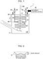
- FIG. 1 is a schematic diagram in which a quenching apparatus according to an embodiment of the present invention is illustrated.
- a quenching apparatus 1 in Fig. 1 performs quenching of a steel material as, for example, a metal sheet S and is employed in cooling facilities provided at the exit side of a soaking zone of a continuous annealing furnace.
- the quenching apparatus 1 for the metal sheet S in Fig. 1 includes a cooling device 10 that cools the metal sheet S and restraining rolls 20 that restrain the cooled metal sheet S in a thickness direction.
- the cooling device 10 cools the metal sheet S by using a cooling fluid CF and includes a cooling tank 11 in which the cooling fluid CF is stored and a plurality of nozzles 12 installed inside the cooling tank 11 and through which the cooling fluid CF is jetted to the surfaces of the metal sheet S.
- Water is stored as the cooling fluid CF in the cooling tank 11, and, for example, the metal sheet S is immersed in the water from the upper surface of the cooling tank 11 toward a conveyance direction BD.
- a sink roll 2 that changes the conveyance direction of the metal sheet S is installed inside the cooling tank 11.
- the plurality of nozzles 12 are formed by, for example, quench nozzles or the like and are installed on two surface sides of the metal sheet S to be arranged in the conveyance direction of the metal sheet S. Consequently, the metal sheet S is cooled by the cooling fluid CF inside the cooling tank 11 and the cooling fluid CF that is jetted through the plurality of nozzles 12. Cooling the metal sheet S by thus using both the cooling tank 11 and the plurality of nozzles 12 stabilizes the boiling state of the surfaces of the metal sheet S and enables uniform shape control.
- the method of cooling is not limited thereto as long as the method can cool the metal sheet S in a desired temperature range.
- the metal sheet S may be cooled by only the cooling tank 11 and may be cooled by only the plurality of nozzles 12.
- the distance between the metal sheet S and the nozzles 12 is important in rapid cooling by liquid quenching. Since a vapor film generated by a boiling phenomenon is broken by liquid jet streams to perform rapid cooling, it is preferable that the nozzles 12 be installed close to the metal sheet S.
- the distance between the tip portion of each of the nozzles 12 and the metal sheet S is preferably more than or equal to 10 mm and less than or equal to 150 mm. When the distance is less than 10 mm, there is a possibility that the metal sheet S is deformed into a flapping state and comes into contact with the nozzles 12. In addition, when the distance is more than 150 mm, the effect of breaking the vapor film weakens and makes it difficult to ensure a sufficient cooling performance.
- the restraining rolls 20 restrain the metal sheet S cooled by the cooling device 10 in the thickness direction and these rolls 20 are respectively installed on both surfaces of metal sheet S inside the cooling tank 11.
- a pair of the restraining rolls 20 are installed to face each other in Fig. 1 but may be installed at positions displaced from each other in the conveyance direction as long as the restraining rolls 20 are configured to perform restraining.
- a pair of the restraining rolls 20 are installed in the example in Fig. 1
- a plurality of pairs of restraining rolls 20 may be installed in the conveyance direction.
- the roll diameter of each of the restraining rolls 20 is preferably more than or equal to 50 mm and less than or equal to 300 mm.
- the material of the restraining rolls 20 is not limited. When general steel rolls are used as the restraining rolls 20 and when the roll diameter of each of the rolls is less than 50 mm, roll rigidity is insufficient. Consequently, causing a uniform restraining force to act on the metal sheet S is made to be difficult due to a flexure, and the restraining rolls 20 may be broken.
- the restraining rolls 20 are installed to be movable in the conveyance direction of the metal sheet S.
- the conveyance direction is a direction in which the metal sheet S is conveyed.
- the quenching apparatus 1 for the metal sheet S includes a roll moving device 30 that moves the restraining rolls 20 and a movement control device 40 that controls the movement of the restraining rolls 20.
- the roll moving device 30 includes publicly known driving means, for example, a motor or the like and is configured to cause the restraining rolls 20 to move toward the conveyance direction BD of the metal sheet S or a direction opposite to the conveyance direction BD in the conveyance direction of the metal sheet S.
- the roll moving device 30 can be suitably produced by combining mechanical components such as a power jack, a screw lifting device formed by a screw mechanism or a gear mechanism, and a less-resistance linear motion guide (LM guide) that uses rolling.
- a power jack a screw lifting device formed by a screw mechanism or a gear mechanism
- LM guide less-resistance linear motion guide
- FIG. 1 an example in which the roll moving device 30 is constituted by a screw lifting device is illustrated.
- Each of the restraining rolls 20 is rotatably attached to one end portion of an L-shape arm 31.
- a screw portion 32, another screw portion (not illustrated) that engages with the screw portion 32, and driving mean (not illustrated) that drives the other screw portion are provided on the other end side of the arm 31.
- the driving means is fixed to a fixation portion (not illustrated). Consequently, when the other screw portion receives torque that is generated by the driving means and rotates, the arm 31 moves in a direction parallel to the conveyance
- the driving means be installed above a liquid surface in the cooling tank 11.
- the driving means be installed in a space that is shielded from the inside of a furnace in which the temperature is high.
- the roll moving device 30 may have a function of causing the restraining rolls 20 to move in the thickness direction of the metal sheet S and restrain the metal sheet S or release restraining. While the method of moving is not particularly limited as long moving is possible, an electric type is more preferable in consideration of responsivity.
- the movement control device 40 is formed by a hardware resource such as a computer and controls the movement of the restraining rolls 20.
- the movement control device 40 controls the operation of the roll moving device 30 to position the restraining rolls 20 such that the metal sheet S is restrained at the position RP at which the metal sheet S has the target temperature.
- the target temperature is preferably set in the temperature range of (TMs + 150)(°C) to (TMf - 150)(°C), where TMs(°C) is a Ms temperature at which a martensitic transformation of the metal sheet S starts and TMf(°C) is a Mf temperature at which the martensitic transformation ends. Consequently, the restraining rolls 20 can restrain a deformation of the metal sheet S at a position at which sudden thermal contraction and transformation expansion occur at the same time in the metal sheet S and can suppress the deformation of the metal sheet S at the time of quenching.
- the movement control device 40 calculates a distance d from the cooling start position SP of cooling of the metal sheet S by the cooling fluid CF to the position RP at which the metal sheet S has the target temperature and is restrained by the restraining rolls 20, and moves the restraining rolls 20 on the basis of the calculated distance d. To calculate the distance d, the movement control device 40 uses the line speed v (mm/s) of the metal sheet S, the cooling start temperature T1(°C), the target temperature T2(°C) at which restraining is performed by the restraining rolls 20, and the cooling rate CV(°C/s) of cooling of the metal sheet S by the cooling device 10.
- the cooling start temperature T1 is the temperature of the metal sheet S just before the cooling start position SP at which cooling of the metal sheet S by the cooling fluid CF is started.
- the temperature just before reaching the cooling start position SP can be calculated on the basis of a cooled state of the metal sheet S until reaching the cooling start position SP or the quenching apparatus 1.
- the temperature of the metal sheet S is measured at the exit side of a soaking zone of a continuous annealing furnace by a contactless thermometer. Then, on the basis of the temperature and a temperature decrease of the metal sheet S due to being naturally cooled until reaching the quenching apparatus 1, the temperature of the metal sheet S just before or at the point of time of reaching the cooling start position SP can be calculated.
- the above-described temperature decrease of the metal sheet S due to being naturally cooled can be obtained previously through an experiment.
- the aforementioned parameters may be successively obtained from set values or actual operation results of a process computer and may be measured by using a speed sensor, a temperature sensor, or the like.
- the cooling rate CV(°C/s) can be expressed using a sheet thickness t of the metal sheet S and a coefficient ⁇ (°C ⁇ mm/s), which indicates cooling conditions such as the shape of the nozzles or the type, the temperature, the jetting amount of the cooling fluid CF that is to be jetted, by Formula (3) below.
- CV ⁇ /t
- the cooling rate CV (°C/s) or ⁇ (°C ⁇ mm/s) that is previously obtained through an experiment, a numerical analysis, and the like is stored. Then, the movement control device 40 obtains the distance d by using Formula (1) or Formula (3) and moves the restraining rolls 20 such that the metal sheet S is restrained at a position corresponding to the obtained distance d.
- the cooling rate CV may be set to 1500(°C/s), which is an intermediate value in the aforementioned range.
- ⁇ may be treated as 1250(°C ⁇ mm/s), which is an intermediate value.
- cooling conditions ⁇ obtained by the above-described cooling rate CV, the sheet thickness t, and Formula (2) may be set.
- the metal sheet S is cooled by the cooling device 10 while being conveyed, and quenching of the metal sheet S is performed.
- the restraining rolls 20 move in the conveyance direction such that the metal sheet S having the target temperature T2 at the position RP is restrained in the thickness direction.
- the movement control device 40 calculates the distance d by using Formula (1) or Formula (3) mentioned above, and the restraining rolls 20 move so as to restrain the metal sheet S at a position corresponding to the calculated distance d.
- the movement of the restraining rolls 20 may be performed successively also during quenching of the metal sheet S.
- the movement control device 40 may calculate the distance d and move the restraining rolls 20, for example, at a timing when the line speed v is changed.
- the line speed of the metal sheet S fluctuates even with respect to a single metal sheet S (in one coil). Therefore, it is more preferable, since a yield by shape defects of portions such as a leading end and a tail end of the metal sheet S where the speed decreases can be improved, that the metal sheet S be movable in the conveyance direction or a direction opposite to the conveyance direction while being restrained by the restraining rolls 20.
- the movement control device 40 may calculate the distance d and move the restraining rolls 20 for every set period.
- the movement distance of the restraining rolls 20 for adjusting the restraining rolls 20 to be at the position RP, at which the metal sheet S is restrained, based on the distance d can be estimated as substantially 10 mm to 150 mm actually.
- the restraining rolls 20 may be lifted and lowered between these nozzles 12 in a state in which an interval between the nozzles 12 are previously widened to about 10 mm to 150 mm.
- the temperature of the restrained metal sheet S can be adjusted by about 10°C to 150°C, and the above-described movement distance of the restraining rolls 20 is actually in a sufficient control adjustment range.
- a case in which the restraining rolls 20 are moved by a larger amount than in the above-described example will be described.
- the composition, the sheet thickness, the line speed, and the like of the metal sheet S are greatly varied, it is required to move the restraining rolls 20 by 150 mm or more to position the restraining rolls 20 at the position RP at which the metal sheet S is restrained.
- a configuration that moves the restraining rolls 20 by 150 mm or more will be described.
- Fig. 9 is a diagram in which another example of the quenching apparatus according to an embodiment of the present invention is illustrated.
- nozzle moving device 60 that moves the nozzles 12.
- the nozzle moving device 60 is disposed on each of two sides of the metal sheet S.
- the nozzle moving device 60 is configured to move the nozzles 12 along the metal sheet S and cause the nozzles 12 to come close to and separate from the metal sheet S.
- the restraining rolls 20 on the two sides of the metal sheet S are shifted from each other in the up-down direction.
- the nozzle moving device 60 includes a lifting device 62 that moves cooling pipes 61 in communication with a corresponding one of the nozzles 12 in the up-down direction of the cooling device 10, and a slider 63 that causes the lifting device 62 to come close to and separate from the metal sheet S.
- the lifting device 62 is configured to be able to lift and lower each of a plurality of the cooling pipes 61 independently.
- the lifting device 62 and the slider 63 may be a lifting device and a slider that have been known.
- a control device which is not illustrated, that controls driving of the lifting device 62 and the slider 63 is provided.
- the quenching apparatus 50 illustrated in Fig. 9 will be described.
- the restraining rolls 20 are moved upward from the position thereof illustrated in Fig. 9(A) , the restraining rolls 20 and the nozzles 12 that are positioned on the upper side of the restraining rolls 20 interfere with each other. Therefore, the nozzles 12 are first separated from the metal sheet S by the slider 63 in the width direction (the left-right direction in Fig. 9 ) of the cooling device 10. In other words, the nozzles 12 are moved to be retracted from the restraining rolls 20.
- the interval between the metal sheet S and the tip portion of each of the nozzles 12 after the nozzles 12 are separated from the metal sheet S is set to an interval with which the restraining rolls 20 and the tip portions of the nozzles 12 do not come into contact with each other.
- the restraining rolls 20 are moved to the upper side or the lower side.
- the restraining rolls 20 are moved to the upper side.
- the restraining rolls 20 are moved to the position RP suitable for the target temperature T2 of the metal sheet S.
- Fig. 9(B) the state thereof is illustrated.
- Fig. 9(B) the restraining rolls 20 and the nozzles 12 are adjacent to each other in the width direction of the cooling tank 11. Therefore, the nozzles 12 that are adjacent to the restraining rolls 20 in the width direction are moved by the lifting device 62 as illustrated in Fig. 9(B) to be retract to the lower side of the restraining rolls 20. Consequently, the restraining rolls 20 and the nozzles 12 do not interfere with each other in either of the up-down direction and the width direction.
- Fig. 9(C) the state thereof is illustrated.
- the nozzles 12 are caused by the slider 63 to come close to the metal sheet S, and the interval therebetween is set and maintained at a preset interval. The movement of the restraining rolls 20 is thus completed.
- Fig. 9(D) the state thereof is illustrated.
- the interval between the nozzles 12 may be widened to about 10 mm to 150 mm, substantially similarly to the example illustrated in Fig. 1 , after the state illustrated in Fig. 9(D) is obtained, and, in this state, the restraining rolls 20 may be moved by about 10 mm to 150 mm to be adjusted to the aforementioned position RP. If allowable in terms of the cooling performance, the state in which the interval between the metal sheet S and the nozzles 12 is widened may be maintained so that the restraining rolls 20 can move by 150 mm or more.
- the restraining rolls 20 it is possible by installing the restraining rolls 20 to be movable in the conveyance direction to control the distance from the cooling start position to the restraining rolls 20 and to restrain the metal sheet S having the target temperature T2 by the restraining rolls 20 regardless of conditions of manufacture of the metal sheet S. As a result, it becomes possible to suppress shape defects of the metal sheet S generated due to conditions of manufacture of the metal sheet S during quenching in continuous annealing facilities.
- the temperature of the metal sheet S conveyed to the quenching apparatus 1 varies depending on conditions of manufacture of the metal sheet, for example, the line speed v, the cooling start temperature T1 of the metal sheet S, the sheet thickness t of the metal sheet S, and the like. Therefore, when the distance d is set to be constant regardless of conditions of manufacture, the temperature of the metal sheet S when the metal sheet S reaches the restraining rolls 20 also varies.
- the deformation suppressing effect is increased in particular when the metal sheet S is a high strength steel sheet (high tensile strength steel sheet).
- high tensile strength steel sheet a high strength steel sheet
- application to manufacture of a steel sheet whose tensile strength is more than or equal to 580 MPa is preferable. While the upper limit of the tensile strength is not particularly limited, the tensile strength may be less than or equal to 2000 MPa in one example.
- high strength steel sheet high tensile strength steel sheet
- a high strength cold rolled steel sheet high strength cold rolled steel sheet
- a hot-dip galvanized steel sheet an electro-galvanized steel sheet
- a hot-dip galvannealed steel sheet and the like that are obtained by performing a surface treatment on high strength cold rolled steel sheets.
- composition of the high strength steel sheet there is presented an example in which, in mass%, C is contained by more than or equal to 0.04% and less than or equal to 0.35%, Si is contained by more than or equal to 0.01% and less than or equal to 2.50%, Mn is contained by more than or equal to 0.80% and less than or equal to 3.70%, P is contained by more than or equal to 0.001% and less than or equal to 0.090%, S is contained by more than or equal to 0.0001% and less than or equal to 0.0050%, sol.Al is contained by more than or equal to 0.005% and less than or equal to 0.065%, at least one or more of Cr, Mo, Nb, V, Ni, Cu, and Ti are each contained, as necessary, by less than or equal to 0.5%, B and Sb are each further contained, as necessary, by less than or equal to 0.01%, and the remainder is constituted by Fe and incidental impurities.
- the metal sheet S is not limited to a steel sheet and may be a
- a temperature TMs which is the Ms temperature of the high tensile strength cold rolled steel sheet, is 300°C
- a temperature TMf which is the Mf temperature thereof, is 250°C. Therefore, the target temperature T2 at a time of passing the restraining rolls 20 may be simply set in the range of 450°C to 100°C, and the target temperature T2 was set to 400°C.
- the cooling start temperature T1 was set to 800°C with the target temperature T2 set to 400°C.
- the temperature of the cooling fluid CF was 30°C, and the cooling rate CV was set to 1500 (°C/s).
- Ten steel sheets after being cooled were collected at every 100 m in the longitudinal direction (that is, the same direction as the conveyance direction of the steel sheets), and the warp amount of each of the steel sheets was checked.
- Fig. 2 is a schematic diagram in which one example of the definition of the warp amount is illustrated. As illustrated in Fig. 2 , the warp amount was defined as a height from a ground contact surface to a highest position of a steel sheet when the steel sheet was placed on a horizontal surface.
- Fig. 3 is a graph showing the relationship between the line speed v and the target temperature in the present invention example
- Fig. 4 is a graph showing the relationship between the line speed v and the warp amount of a steel sheet as the metal sheet S in the present invention example.
- the line speed v was varied, to control the temperature (°C) at the time of passing the restraining rolls 20 to be the target temperature 400 ⁇ 25°C by moving the restraining rolls 20 in accordance with the line speed v and varying the distance d.
- all of the warp amounts of the steel sheets decreased to be less than or equal to 10 mm, as illustrated in Fig. 4 . Consequently, a variation, in other words, a difference between a maximum value and a minimum value of the warp amount was suppressed to be 4.2 mm.
- Fig. 5 is a graph showing the relationship between the line speed v and the target temperature in Comparative example 1
- Fig. 6 is a graph showing the relationship between the line speed v and the warp amount of a steel sheet as the metal sheet S in Comparative example 1.
- a quenching apparatus in which the restraining rolls 20 such as those in Patent Literature 1 are fixed was used, and the other conditions were the same as those in the aforementioned present invention example.
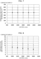
- Fig. 7 is a graph showing the relationship between the line speed v and the target temperature in Comparative example 2
- Fig. 8 is a graph showing the relationship between the line speed v and the warp amount of a steel sheet as the metal sheet S in Comparative example 2.
- the distance d was controlled by the cooling start position by moving the movable masking member with the restraining rolls 20 being fixed.
- Other conditions were set to be the same as those in the present invention example, and the aforementioned high tensile strength cold rolled steel sheet was manufactured.
- the temperature (°C) at the time of passing the restraining rolls 20 greatly varied in Comparative example 2 regardless of the line speed v (mm/s), which is a condition of manufacture of the steel sheet, and was uncontrollable. Therefore, under all conditions, the temperature (°C) at the time of passing the restraining rolls was out of the range of 450°C to 100°C. Then, as illustrated in Fig. 8 , the warp amount of the steel sheet was more than or equal to 10 mm, and the effect of suppressing a deformation was insufficient. As a result, the variation (i.e., the difference between the maximum value and the minimum value) in the warp amount was increased to be 9.2 mm.
- the embodiment of the present invention is not limited to the aforementioned embodiment, and various changes can be added thereto.
- the target temperature T2 is (TMs + 150)(°C) to (TMf - 150)(°C) in the example presented in the aforementioned embodiment, the target temperature T2 is not limited thereto.
- the target temperature T2 may be not limited to (TMs + 150)(°C) to (TMf - 150)(°C) when absence of variations in the shape of the metal sheet S in terms of, for example, the warp amount and the like is simply required from the point of view of ensuring flexibility in processing and operation in subsequent steps.
- the target temperature T2 is previously determined in consideration of a predicted shape (for example, the warp amount) while ensuring of flexibility in processing and operation in subsequent steps and the like are taken into consideration, and the distance d from the cooling start position to the restraining rolls 20 is controlled by positional adjustment of the restraining rolls 20. Then, the temperature of the metal sheet S at the time of passing the restraining rolls 20 is caused to be the previously determined temperature T2 so that the shape (for example, the warp amount) of the metal sheet S is substantially the same, for example, a variation in the warp amount defined in Fig. 2 is 4 mm or less.
- the restraining rolls 20 are not limited to being provided as a pair. A plurality of pairs of the restraining rolls 20 or a plurality of the restraining rolls 20 may be provided. In such a case, positions of the restraining roll pairs as a whole may be collectively controlled, or a mechanism that controls the position and opening/closing of each of a plurality of the restraining rolls may be employed.
Landscapes
- Chemical & Material Sciences (AREA)
- Engineering & Computer Science (AREA)
- Mechanical Engineering (AREA)
- Materials Engineering (AREA)
- Metallurgy (AREA)
- Organic Chemistry (AREA)
- Physics & Mathematics (AREA)
- Thermal Sciences (AREA)
- Crystallography & Structural Chemistry (AREA)
- Heat Treatment Of Strip Materials And Filament Materials (AREA)
- Control Of Heat Treatment Processes (AREA)
Abstract
Description
- The present invention relates to a quenching apparatus that performs annealing while continuously conveying a metal sheet, a quenching method, and a method of manufacturing a metal sheet.
- In continuous annealing facilities in which annealing is performed while continuously conveying a metal sheet, the metal sheet is cooled after heated and causes a phase transformation, and the microstructure of the metal sheet is thereby made. In particular, in the automotive industry, there is an increased demand for a thinned high tension steel sheet (high tensile strength steel sheet) to achieve both a weight reduction of a vehicle body and crash safety. In manufacture of the high tensile strength steel sheet, a technique of rapidly cooling a steel sheet is important. A water quenching method is known as one of the technique in which the cooling rate of cooling of a metal sheet is highest. In the water quenching method, at the same time when a heated metal sheet is immersed in water, cooling water is jetted through a quench nozzle provided in the water to the metal sheet, and the metal sheet is thereby quenched.
- At the time of quenching of the metal sheet, shape defects such as warps, wavy deformations, and the like are generated in the metal sheet. This is caused by thermal contraction or the like of the metal sheet due to being rapidly cooled. In particular, when the temperature of the metal sheet changes from a temperature Ms at which a martensitic transformation starts to a temperature Mf at which the martensitic transformation ends, sudden thermal contraction and transformation expansion occur at the same time.
- Thus, various methods for preventing shape defects of metal sheets at the time of quenching have been proposed (refer to, for example,
Patent Literature 1 and Patent Literature 2).Patent Literature 1 proposes a method of restraining a metal sheet by a pair of restraining rolls that are provided in a cooling liquid when the temperature of the metal sheet is in the range of (TMs + 150)(°C) to (TMf - 150)(°C), where TMs(°C) is a Ms temperature at which a martensitic transformation of the metal sheet starts and TMf(°C) is a Mf temperature at which the martensitic transformation ends. -
Patent Literature 2 discloses that, while a metal sheet is restrained by restraining rolls, a distance between a position at which cooling of the metal sheet by a cooling fluid is started and the restraining rolls is controlled by a movable masking member when a quenching method in which cooling is performed by jetting water through a plurality of water jetting nozzles to surfaces of the metal sheet is performed. Further, as inPatent Literature 1, there is proposed a method in which a metal sheet with a temperature from (TMs + 150)(°C) to (TMf - 150)(°C), where TMs(°C) is the Ms temperature at which a martensitic transformation of the metal sheet starts and TMf(°C) is the Mf temperature at which the martensitic transformation ends, is caused to pass the restraining rolls. -
- PTL 1:
Japanese Patent No. 6094722 - PTL 2:
Japanese Unexamined Patent Application Publication No. 2019-90106 - In the method described in
Patent Literature 1, however, the position at which the temperature of the metal sheet is in the range of (TMs + 150)(°C) to (TMf - 150)(°C) varies depending on conditions of manufacture of the metal sheet. Therefore, it may be impossible for the restraining rolls to restrain the metal sheet at a position at which the temperature of the metal sheet is in the range of (TMs + 150)(°C) to (TMf-150)(°C), and variations in the shape of the metal sheet may be generated. - In the method described in
Patent Literature 2, water that hits the movable masking member falls by gravity and interferes with water that is jetted through the water jetting nozzles at a lower portion of the movable masking member, thereby causing a cooling performance of cooling of the metal sheet to be unstable. In addition, since masking is performed for each nozzle, the cooling performance varies in steps (discontinuously) and, as a result, causes the position at which the temperature of the metal sheet is in the range of (TMs + 150)(°C) to (TMf - 150)(°C) to be unstable, and variations in the shape of the metal sheet may be generated. - The present invention has been made to solve such problems, and an object of the present invention is to provide a quenching apparatus capable of highly accurately controlling the temperature of a metal sheet at a position at which the metal sheet is restrained and suppressing generation of variations in the shape of the metal sheet at the time of quenching, a quenching method, and a method of manufacturing a metal-sheet product.
-
- [1] A metal-sheet quenching apparatus that cools a metal sheet while conveying the metal sheet, the metal-sheet quenching apparatus including: a cooling device that cools the metal sheet that is conveyed; a restraining roll that conveys the metal sheet cooled by the cooling device while restraining the metal sheet in a thickness direction; a roll moving device that moves the restraining roll in a conveyance direction of the metal sheet; and a movement control device that adjusts a position of the restraining roll by controlling an operation of the roll moving device.
- [2] The metal-sheet quenching apparatus described in [1], in which the cooling device includes a plurality of nozzles through which a cooling fluid is jetted to the metal sheet to cool the metal sheet.
- [3] The metal-sheet quenching apparatus described in [1] or [2], in which the cooling device includes a cooling tank in which the metal sheet is immersed and cooled.
- [4] The metal-sheet quenching apparatus described in any one of [1] to [3], in which the movement control device controls the operation of the roll moving device to position the restraining roll such that the restraining roll restrains the metal sheet at a position at which the metal sheet has a target temperature.
- [5] The metal-sheet quenching apparatus described in [4], in which the target temperature is set in a temperature range of (TMs + 150)(°C) to (TMf - 150)(°C), where TMs(°C) is a Ms temperature at which a martensitic transformation of the metal sheet starts and TMf(°C) is a Mf temperature at which the martensitic transformation ends.
- [6] The metal-sheet quenching apparatus described in [4] or [5], in which the movement control device sets a distance from a cooling start position by the cooling device to the restraining roll based on a line speed of the metal sheet, a cooling start temperature of the metal sheet at a time when cooling by the cooling device is started, the target temperature, and a cooling rate of cooling of the metal sheet, and moves the position of the restraining roll such that the set distance is achieved.
- [7] The metal-sheet quenching apparatus described in [6], in which the movement control device obtains a distance d (mm) from the cooling start position to the restraining roll by Formula (1) below:

- [8] The metal-sheet quenching apparatus described in [7], in which, based on a sheet thickness t of the metal sheet and a coefficient α indicating a condition of cooling of the metal sheet, the cooling rate CV is set as CV = α/t in the movement control device.
- [9] A metal-sheet quenching method in which a metal sheet is cooled while being conveyed, the method including: moving a restraining roll in a conveyance direction of the metal sheet such that, when the metal sheet that has been cooled is restrained by the restraining roll in a thickness direction, the metal sheet is restrained at a position at which the metal sheet has a target temperature.
- [10] The metal-sheet quenching method described in [9], in which the target temperature is set in a temperature range of (TMs + 150)(°C) to (TMf - 150)(°C), where TMs(°C) is a Ms temperature at which a martensitic transformation of the metal sheet starts and TMf(°C) is a Mf temperature at which the martensitic transformation ends.
- [11] The metal-sheet quenching method described in [9] or [10], in which moving of the restraining roll is performed by setting a distance from a cooling start position to the restraining roll based on a line speed of the metal sheet, a cooling start temperature of the metal sheet at a time when cooling is started, the target temperature, and a cooling rate of cooling of the metal sheet and moving the restraining roll such that the set distance is achieved.
- [12] The metal-sheet quenching method described in [11], in which, as the distance from the cooling start position to the restraining roll, a distance d (mm) from the cooling start position to the restraining roll is obtained by Formula (1) below:

- [13] The metal-sheet quenching method described in [12], in which, based on a sheet thickness t of the metal sheet and a coefficient α indicating a condition of cooling of the metal sheet, the cooling rate CV is set as CV = α/t.
- [14] A method of manufacturing a high strength cold rolled steel sheet, the method using the metal-sheet quenching method described in any one of [9] to [13].
- [15] A method of manufacturing a high strength steel sheet, the method comprising performing any of a hot-dip galvanizing treatment, an electro-galvanizing treatment, or a hot-dip galvannealing treatment on a high strength steel sheet obtained by the method described in [14]. Advantageous Effects of Invention
- According to the present invention, by adjusting the position of restraining rolls in a conveyance direction of a metal sheet in accordance with the temperature of the metal sheet at the time of quenching of the metal sheet to control the distance from a cooling start position to the restraining rolls, it is possible to suppress variations in the shape of metal sheet generated at the time of quenching.
-
- [
Fig. 1] Fig. 1 is a schematic diagram in which a quenching apparatus according to an embodiment of the present invention is illustrated. - [
Fig. 2] Fig. 2 is a schematic diagram in which one example of the definition of a warp amount of a metal sheet is illustrated. - [
Fig. 3] Fig. 3 is a graph showing a relationship between a line speed and a target temperature in a present invention example. - [
Fig. 4] Fig. 4 is a graph showing a relationship between a line speed and a warp amount of a metal sheet in a present invention example. - [
Fig. 5] Fig. 5 is a graph showing a relationship between a line speed and a target temperature in Comparative example 1. - [
Fig. 6] Fig. 6 is a graph showing a relationship between a line speed and a warp amount of a metal sheet in Comparative example 1. - [
Fig. 7] Fig. 7 is a graph showing a relationship between a line speed and a target temperature in Comparative example 2. - [
Fig. 8] Fig. 8 is a graph showing a relationship between a line speed and a warp amount of a metal sheet in Comparative example 2. - [
Fig. 9] Fig. 9 describes movements of restraining rolls and nozzles in another example of the quenching apparatus according to an embodiment of the present invention. - An embodiment of the present invention will be described on the basis of the drawings.
Fig. 1 is a schematic diagram in which a quenching apparatus according to an embodiment of the present invention is illustrated. Aquenching apparatus 1 inFig. 1 performs quenching of a steel material as, for example, a metal sheet S and is employed in cooling facilities provided at the exit side of a soaking zone of a continuous annealing furnace. Thequenching apparatus 1 for the metal sheet S inFig. 1 includes acooling device 10 that cools the metal sheet S andrestraining rolls 20 that restrain the cooled metal sheet S in a thickness direction. - The
cooling device 10 cools the metal sheet S by using a cooling fluid CF and includes acooling tank 11 in which the cooling fluid CF is stored and a plurality ofnozzles 12 installed inside thecooling tank 11 and through which the cooling fluid CF is jetted to the surfaces of the metal sheet S. Water is stored as the cooling fluid CF in thecooling tank 11, and, for example, the metal sheet S is immersed in the water from the upper surface of thecooling tank 11 toward a conveyance direction BD. Asink roll 2 that changes the conveyance direction of the metal sheet S is installed inside thecooling tank 11. - The plurality of
nozzles 12 are formed by, for example, quench nozzles or the like and are installed on two surface sides of the metal sheet S to be arranged in the conveyance direction of the metal sheet S. Consequently, the metal sheet S is cooled by the cooling fluid CF inside thecooling tank 11 and the cooling fluid CF that is jetted through the plurality ofnozzles 12. Cooling the metal sheet S by thus using both thecooling tank 11 and the plurality ofnozzles 12 stabilizes the boiling state of the surfaces of the metal sheet S and enables uniform shape control. - While water quenching that uses water as the cooling fluid CF is employed in the example, oil cooling that uses an oil as the cooling fluid CF may be employed. In addition, while the plurality of
nozzles 12 are installed inside thecooling tank 11 in the example inFig. 1 , the method of cooling is not limited thereto as long as the method can cool the metal sheet S in a desired temperature range. For example, the metal sheet S may be cooled by only thecooling tank 11 and may be cooled by only the plurality ofnozzles 12. - When the
nozzles 12 are installed inside thecooling tank 11, the distance between the metal sheet S and thenozzles 12 is important in rapid cooling by liquid quenching. Since a vapor film generated by a boiling phenomenon is broken by liquid jet streams to perform rapid cooling, it is preferable that thenozzles 12 be installed close to the metal sheet S. The distance between the tip portion of each of thenozzles 12 and the metal sheet S is preferably more than or equal to 10 mm and less than or equal to 150 mm. When the distance is less than 10 mm, there is a possibility that the metal sheet S is deformed into a flapping state and comes into contact with thenozzles 12. In addition, when the distance is more than 150 mm, the effect of breaking the vapor film weakens and makes it difficult to ensure a sufficient cooling performance. - The restraining rolls 20 restrain the metal sheet S cooled by the cooling
device 10 in the thickness direction and theserolls 20 are respectively installed on both surfaces of metal sheet S inside thecooling tank 11. A pair of the restraining rolls 20 are installed to face each other inFig. 1 but may be installed at positions displaced from each other in the conveyance direction as long as the restraining rolls 20 are configured to perform restraining. In addition, while a pair of the restraining rolls 20 are installed in the example inFig. 1 , a plurality of pairs of restraining rolls 20 may be installed in the conveyance direction. - In consideration of the correlation between roll rigidity and a flexure due to a restraining stress, the roll diameter of each of the restraining rolls 20 is preferably more than or equal to 50 mm and less than or equal to 300 mm. The material of the restraining rolls 20 is not limited. When general steel rolls are used as the restraining rolls 20 and when the roll diameter of each of the rolls is less than 50 mm, roll rigidity is insufficient. Consequently, causing a uniform restraining force to act on the metal sheet S is made to be difficult due to a flexure, and the restraining rolls 20 may be broken. Meanwhile, when the roll diameter is more than 300 mm, a section in which a jet stream from each of the
nozzles 12 does not reach the metal sheet S is lengthened, and there is a possibility that breakage of the vapor film becomes insufficient and the cooling performance decreases. - The restraining rolls 20 are installed to be movable in the conveyance direction of the metal sheet S. Here, the conveyance direction is a direction in which the metal sheet S is conveyed. Specifically, the
quenching apparatus 1 for the metal sheet S includes aroll moving device 30 that moves the restraining rolls 20 and amovement control device 40 that controls the movement of the restraining rolls 20. Theroll moving device 30 includes publicly known driving means, for example, a motor or the like and is configured to cause the restraining rolls 20 to move toward the conveyance direction BD of the metal sheet S or a direction opposite to the conveyance direction BD in the conveyance direction of the metal sheet S. Specifically, theroll moving device 30 can be suitably produced by combining mechanical components such as a power jack, a screw lifting device formed by a screw mechanism or a gear mechanism, and a less-resistance linear motion guide (LM guide) that uses rolling. InFig. 1 , an example in which theroll moving device 30 is constituted by a screw lifting device is illustrated. Each of the restraining rolls 20 is rotatably attached to one end portion of an L-shape arm 31. Ascrew portion 32, another screw portion (not illustrated) that engages with thescrew portion 32, and driving mean (not illustrated) that drives the other screw portion are provided on the other end side of thearm 31. The driving means is fixed to a fixation portion (not illustrated). Consequently, when the other screw portion receives torque that is generated by the driving means and rotates, thearm 31 moves in a direction parallel to the conveyance direction BD along with the rotation. - When the above-described driving means is immersed in a liquid, maintenance of the driving means may be difficult. Therefore, it is preferable that the driving means be installed above a liquid surface in the
cooling tank 11. In addition, it is preferable that the driving means be installed in a space that is shielded from the inside of a furnace in which the temperature is high. - The
roll moving device 30 may have a function of causing the restraining rolls 20 to move in the thickness direction of the metal sheet S and restrain the metal sheet S or release restraining. While the method of moving is not particularly limited as long moving is possible, an electric type is more preferable in consideration of responsivity. - The
movement control device 40 is formed by a hardware resource such as a computer and controls the movement of the restraining rolls 20. In particular, themovement control device 40 controls the operation of theroll moving device 30 to position the restraining rolls 20 such that the metal sheet S is restrained at the position RP at which the metal sheet S has the target temperature. Here, the target temperature is preferably set in the temperature range of (TMs + 150)(°C) to (TMf - 150)(°C), where TMs(°C) is a Ms temperature at which a martensitic transformation of the metal sheet S starts and TMf(°C) is a Mf temperature at which the martensitic transformation ends. Consequently, the restraining rolls 20 can restrain a deformation of the metal sheet S at a position at which sudden thermal contraction and transformation expansion occur at the same time in the metal sheet S and can suppress the deformation of the metal sheet S at the time of quenching. - The
movement control device 40 calculates a distance d from the cooling start position SP of cooling of the metal sheet S by the cooling fluid CF to the position RP at which the metal sheet S has the target temperature and is restrained by the restraining rolls 20, and moves the restraining rolls 20 on the basis of the calculated distance d. To calculate the distance d, themovement control device 40 uses the line speed v (mm/s) of the metal sheet S, the cooling start temperature T1(°C), the target temperature T2(°C) at which restraining is performed by the restraining rolls 20, and the cooling rate CV(°C/s) of cooling of the metal sheet S by the coolingdevice 10. Here, the cooling start temperature T1 is the temperature of the metal sheet S just before the cooling start position SP at which cooling of the metal sheet S by the cooling fluid CF is started. For example, the temperature just before reaching the cooling start position SP can be calculated on the basis of a cooled state of the metal sheet S until reaching the cooling start position SP or thequenching apparatus 1. Specifically, the temperature of the metal sheet S is measured at the exit side of a soaking zone of a continuous annealing furnace by a contactless thermometer. Then, on the basis of the temperature and a temperature decrease of the metal sheet S due to being naturally cooled until reaching thequenching apparatus 1, the temperature of the metal sheet S just before or at the point of time of reaching the cooling start position SP can be calculated. The above-described temperature decrease of the metal sheet S due to being naturally cooled can be obtained previously through an experiment. Note that the aforementioned parameters may be successively obtained from set values or actual operation results of a process computer and may be measured by using a speed sensor, a temperature sensor, or the like. - Specifically, the relationship between the distance d and the cooling rate CV(°C/s) is expressed by Formula (1) below.


- The cooling rate CV(°C/s) can be expressed using a sheet thickness t of the metal sheet S and a coefficient α(°C·mm/s), which indicates cooling conditions such as the shape of the nozzles or the type, the temperature, the jetting amount of the cooling fluid CF that is to be jetted, by Formula (3) below.

- By substituting Formula (2) for Formula (1), the distance d can be expressed by Formula (3) below.

- In the
movement control device 40, the cooling rate CV(°C/s) or α(°C·mm/s) that is previously obtained through an experiment, a numerical analysis, and the like is stored. Then, themovement control device 40 obtains the distance d by using Formula (1) or Formula (3) and moves the restraining rolls 20 such that the metal sheet S is restrained at a position corresponding to the obtained distance d. Note that the cooling rate CV is a value that is determined in accordance with the sheet thickness and the like. When the sheet thickness is 1 to 2 mm, the cooling rate CV = 1000 to 2000(°C/s), and α = 500 to 2000(°C·mm/s). Thus, in themovement control device 40, the cooling rate CV may be set to 1500(°C/s), which is an intermediate value in the aforementioned range. In this case, α may be treated as 1250(°C·mm/s), which is an intermediate value. As described above, cooling conditions α obtained by the above-described cooling rate CV, the sheet thickness t, and Formula (2) may be set. - With reference to
Fig. 1 , a quenching method and a method of manufacturing the metal sheet S in the present invention will be described. First, the metal sheet S is cooled by the coolingdevice 10 while being conveyed, and quenching of the metal sheet S is performed. At this time, the restraining rolls 20 move in the conveyance direction such that the metal sheet S having the target temperature T2 at the position RP is restrained in the thickness direction. At this time, themovement control device 40 calculates the distance d by using Formula (1) or Formula (3) mentioned above, and the restraining rolls 20 move so as to restrain the metal sheet S at a position corresponding to the calculated distance d. Note that the movement of the restraining rolls 20 may be performed successively also during quenching of the metal sheet S. Themovement control device 40 may calculate the distance d and move the restraining rolls 20, for example, at a timing when the line speed v is changed. - The line speed of the metal sheet S fluctuates even with respect to a single metal sheet S (in one coil). Therefore, it is more preferable, since a yield by shape defects of portions such as a leading end and a tail end of the metal sheet S where the speed decreases can be improved, that the metal sheet S be movable in the conveyance direction or a direction opposite to the conveyance direction while being restrained by the restraining rolls 20. Alternatively, the
movement control device 40 may calculate the distance d and move the restraining rolls 20 for every set period. - The movement distance of the restraining rolls 20 for adjusting the restraining rolls 20 to be at the position RP, at which the metal sheet S is restrained, based on the distance d can be estimated as substantially 10 mm to 150 mm actually. As illustrated in
Fig. 1 , when thenozzles 12 are installed inside thecooling tank 11, the restraining rolls 20 may be lifted and lowered between thesenozzles 12 in a state in which an interval between thenozzles 12 are previously widened to about 10 mm to 150 mm. Rapid cooling by liquid jet streams has, for example, a cooling performance of about 1000°C/sec, and, when the traveling speed of the metal sheet S is 60 m/min (= 1000 mm/sec), the temperature varies by about 100°C with a distance of 100 mm. In other words, when the restraining rolls 20 can be lifted and lowered in the range of 10 mm to 150 mm, the temperature of the restrained metal sheet S can be adjusted by about 10°C to 150°C, and the above-described movement distance of the restraining rolls 20 is actually in a sufficient control adjustment range. - Here, a case in which the restraining rolls 20 are moved by a larger amount than in the above-described example will be described. When the composition, the sheet thickness, the line speed, and the like of the metal sheet S are greatly varied, it is required to move the restraining rolls 20 by 150 mm or more to position the restraining rolls 20 at the position RP at which the metal sheet S is restrained. A configuration that moves the restraining rolls 20 by 150 mm or more will be described.
Fig. 9 is a diagram in which another example of the quenching apparatus according to an embodiment of the present invention is illustrated. A quenchingapparatus 50 illustrated inFig. 9 includes, in addition to theroll moving device 30 that moves the restraining rolls 20, anozzle moving device 60 that moves thenozzles 12. As illustrated inFig. 9(A) , thenozzle moving device 60 is disposed on each of two sides of the metal sheet S. Thenozzle moving device 60 is configured to move thenozzles 12 along the metal sheet S and cause thenozzles 12 to come close to and separate from the metal sheet S. In the example illustrated inFig. 9 , the restraining rolls 20 on the two sides of the metal sheet S are shifted from each other in the up-down direction. - As illustrated in
Fig. 9 , thenozzle moving device 60 includes alifting device 62 that moves coolingpipes 61 in communication with a corresponding one of thenozzles 12 in the up-down direction of thecooling device 10, and aslider 63 that causes thelifting device 62 to come close to and separate from the metal sheet S. The liftingdevice 62 is configured to be able to lift and lower each of a plurality of the coolingpipes 61 independently. Note that thelifting device 62 and theslider 63 may be a lifting device and a slider that have been known. In addition, a control device, which is not illustrated, that controls driving of thelifting device 62 and theslider 63 is provided. - Next, an operation of the quenching
apparatus 50 illustrated inFig. 9 will be described. When the restraining rolls 20 are moved upward from the position thereof illustrated inFig. 9(A) , the restraining rolls 20 and thenozzles 12 that are positioned on the upper side of the restraining rolls 20 interfere with each other. Therefore, thenozzles 12 are first separated from the metal sheet S by theslider 63 in the width direction (the left-right direction inFig. 9 ) of thecooling device 10. In other words, thenozzles 12 are moved to be retracted from the restraining rolls 20. The interval between the metal sheet S and the tip portion of each of thenozzles 12 after thenozzles 12 are separated from the metal sheet S is set to an interval with which the restraining rolls 20 and the tip portions of thenozzles 12 do not come into contact with each other. In this state, the restraining rolls 20 are moved to the upper side or the lower side. InFig. 9 , the restraining rolls 20 are moved to the upper side. In other words, the restraining rolls 20 are moved to the position RP suitable for the target temperature T2 of the metal sheet S. InFig. 9(B) , the state thereof is illustrated. - In the state illustrated in
Fig. 9(B) , the restraining rolls 20 and thenozzles 12 are adjacent to each other in the width direction of thecooling tank 11. Therefore, thenozzles 12 that are adjacent to the restraining rolls 20 in the width direction are moved by the liftingdevice 62 as illustrated inFig. 9(B) to be retract to the lower side of the restraining rolls 20. Consequently, the restraining rolls 20 and thenozzles 12 do not interfere with each other in either of the up-down direction and the width direction. InFig. 9(C) , the state thereof is illustrated. Next, thenozzles 12 are caused by theslider 63 to come close to the metal sheet S, and the interval therebetween is set and maintained at a preset interval. The movement of the restraining rolls 20 is thus completed. InFig. 9(D) , the state thereof is illustrated. - Note that the interval between the
nozzles 12 may be widened to about 10 mm to 150 mm, substantially similarly to the example illustrated inFig. 1 , after the state illustrated inFig. 9(D) is obtained, and, in this state, the restraining rolls 20 may be moved by about 10 mm to 150 mm to be adjusted to the aforementioned position RP. If allowable in terms of the cooling performance, the state in which the interval between the metal sheet S and thenozzles 12 is widened may be maintained so that the restraining rolls 20 can move by 150 mm or more. - According to the aforementioned embodiment, it is possible by installing the restraining rolls 20 to be movable in the conveyance direction to control the distance from the cooling start position to the restraining rolls 20 and to restrain the metal sheet S having the target temperature T2 by the restraining rolls 20 regardless of conditions of manufacture of the metal sheet S. As a result, it becomes possible to suppress shape defects of the metal sheet S generated due to conditions of manufacture of the metal sheet S during quenching in continuous annealing facilities.
- In other words, the temperature of the metal sheet S conveyed to the
quenching apparatus 1 varies depending on conditions of manufacture of the metal sheet, for example, the line speed v, the cooling start temperature T1 of the metal sheet S, the sheet thickness t of the metal sheet S, and the like. Therefore, when the distance d is set to be constant regardless of conditions of manufacture, the temperature of the metal sheet S when the metal sheet S reaches the restraining rolls 20 also varies. - It has been found that varying the positions of the restraining rolls 20 is effective to precisely perform shape control at an optimal temperature position, which is different depending on conditions of manufacture to solve this problem. Since the restraining rolls 20 themselves move, it is possible, without causing instability of the cooling form, to restrain the metal sheet S in the target temperature range even when conditions of manufacture vary.
- In particular, it is possible to reduce a shape having intricate uneven irregularities, which are generated when a martensitic transformation occurs during rapid cooling of the metal sheet S and causes volume expansion of the microstructure. Therefore, the deformation suppressing effect is increased in particular when the metal sheet S is a high strength steel sheet (high tensile strength steel sheet). Specifically, application to manufacture of a steel sheet whose tensile strength is more than or equal to 580 MPa is preferable. While the upper limit of the tensile strength is not particularly limited, the tensile strength may be less than or equal to 2000 MPa in one example. As examples of the aforementioned high strength steel sheet (high tensile strength steel sheet), there are presented a high strength cold rolled steel sheet, and a hot-dip galvanized steel sheet, an electro-galvanized steel sheet, a hot-dip galvannealed steel sheet, and the like that are obtained by performing a surface treatment on high strength cold rolled steel sheets.
- As a specific example of the composition of the high strength steel sheet, there is presented an example in which, in mass%, C is contained by more than or equal to 0.04% and less than or equal to 0.35%, Si is contained by more than or equal to 0.01% and less than or equal to 2.50%, Mn is contained by more than or equal to 0.80% and less than or equal to 3.70%, P is contained by more than or equal to 0.001% and less than or equal to 0.090%, S is contained by more than or equal to 0.0001% and less than or equal to 0.0050%, sol.Al is contained by more than or equal to 0.005% and less than or equal to 0.065%, at least one or more of Cr, Mo, Nb, V, Ni, Cu, and Ti are each contained, as necessary, by less than or equal to 0.5%, B and Sb are each further contained, as necessary, by less than or equal to 0.01%, and the remainder is constituted by Fe and incidental impurities. Note that the metal sheet S is not limited to a steel sheet and may be a metal sheet other than a steel sheet.
- An example of the present invention will be described. As a present invention example, quenching of a high tensile strength cold rolled steel sheet that is in a tensile strength class of 1470 MPa and that has the sheet thickness t of 1.0 mm and a sheet width of 1000 mm was performed by using the
quenching apparatus 1 according to the aforementioned embodiment of the present invention. As the composition of the high tensile strength cold rolled steel sheet in the tensile strength class of 1470 MPa, C is contained by 0.20%, Si is contained by 1.0%, Mn is contained by 2.3%, P is contained by 0.005%, and S is contained by 0.002% in mass%. A temperature TMs, which is the Ms temperature of the high tensile strength cold rolled steel sheet, is 300°C, and a temperature TMf, which is the Mf temperature thereof, is 250°C. Therefore, the target temperature T2 at a time of passing the restraining rolls 20 may be simply set in the range of 450°C to 100°C, and the target temperature T2 was set to 400°C. In addition, the cooling start temperature T1 was set to 800°C with the target temperature T2 set to 400°C. The temperature of the cooling fluid CF was 30°C, and the cooling rate CV was set to 1500 (°C/s). - The line speed v was varied in the range of 1000 to 3000 mm/s as a variation in conditions of manufacture, and in accordance with the variation in the line speed v, the distance d (mm) was controlled in the range in which d = 267 to 800 m on the basis of Formula (1). Ten steel sheets after being cooled were collected at every 100 m in the longitudinal direction (that is, the same direction as the conveyance direction of the steel sheets), and the warp amount of each of the steel sheets was checked.
Fig. 2 is a schematic diagram in which one example of the definition of the warp amount is illustrated. As illustrated inFig. 2 , the warp amount was defined as a height from a ground contact surface to a highest position of a steel sheet when the steel sheet was placed on a horizontal surface. -
Fig. 3 is a graph showing the relationship between the line speed v and the target temperature in the present invention example, andFig. 4 is a graph showing the relationship between the line speed v and the warp amount of a steel sheet as the metal sheet S in the present invention example. As illustrated inFig. 3 , it was possible, even when the line speed v was varied, to control the temperature (°C) at the time of passing the restraining rolls 20 to be thetarget temperature 400±25°C by moving the restraining rolls 20 in accordance with the line speed v and varying the distance d. As a result, all of the warp amounts of the steel sheets decreased to be less than or equal to 10 mm, as illustrated inFig. 4 . Consequently, a variation, in other words, a difference between a maximum value and a minimum value of the warp amount was suppressed to be 4.2 mm. -
Fig. 5 is a graph showing the relationship between the line speed v and the target temperature in Comparative example 1, andFig. 6 is a graph showing the relationship between the line speed v and the warp amount of a steel sheet as the metal sheet S in Comparative example 1. As Comparative example 1, a quenching apparatus in which the restraining rolls 20 such as those inPatent Literature 1 are fixed was used, and the other conditions were the same as those in the aforementioned present invention example. In Comparative example 1, the distance d (mm) from the cooling start position to the restraining rolls 20 was fixed as d = 400 mm. - In Comparative example 1, as illustrated in
Fig. 5 , the temperature (°C) at the time of passing the restraining rolls greatly varied depending on the line speed v (mm/s) and was uncontrollable. Therefore, under conditions other than v = 1000 mm/s and v = 1500 mm/s, the temperature (°C) at the time of passing the restraining rolls 20 was out of the range of 450°C to 100°C. As a result, under conditions other than v = 1000 mm/s and v = 1500 mm/s, all of the warp amounts of the steel sheets were more than or equal to 10 mm, as illustrated inFig. 6 , and the effect of suppressing a deformation was insufficient. As a result, a variation, which is a difference between a maximum value and a minimum value of the warp amount, was increased to be 10.3 mm. -
Fig. 7 is a graph showing the relationship between the line speed v and the target temperature in Comparative example 2, andFig. 8 is a graph showing the relationship between the line speed v and the warp amount of a steel sheet as the metal sheet S in Comparative example 2. As Comparative example 2, as indicated inPatent Literature 2, the distance d was controlled by the cooling start position by moving the movable masking member with the restraining rolls 20 being fixed. Other conditions were set to be the same as those in the present invention example, and the aforementioned high tensile strength cold rolled steel sheet was manufactured. - As illustrated in
Fig. 7 , the temperature (°C) at the time of passing the restraining rolls 20 greatly varied in Comparative example 2 regardless of the line speed v (mm/s), which is a condition of manufacture of the steel sheet, and was uncontrollable. Therefore, under all conditions, the temperature (°C) at the time of passing the restraining rolls was out of the range of 450°C to 100°C. Then, as illustrated inFig. 8 , the warp amount of the steel sheet was more than or equal to 10 mm, and the effect of suppressing a deformation was insufficient. As a result, the variation (i.e., the difference between the maximum value and the minimum value) in the warp amount was increased to be 9.2 mm. - Note that the embodiment of the present invention is not limited to the aforementioned embodiment, and various changes can be added thereto. For example, while the target temperature T2 is (TMs + 150)(°C) to (TMf - 150)(°C) in the example presented in the aforementioned embodiment, the target temperature T2 is not limited thereto. The target temperature T2 may be not limited to (TMs + 150)(°C) to (TMf - 150)(°C) when absence of variations in the shape of the metal sheet S in terms of, for example, the warp amount and the like is simply required from the point of view of ensuring flexibility in processing and operation in subsequent steps.
- In this case, the target temperature T2 is previously determined in consideration of a predicted shape (for example, the warp amount) while ensuring of flexibility in processing and operation in subsequent steps and the like are taken into consideration, and the distance d from the cooling start position to the restraining rolls 20 is controlled by positional adjustment of the restraining rolls 20. Then, the temperature of the metal sheet S at the time of passing the restraining rolls 20 is caused to be the previously determined temperature T2 so that the shape (for example, the warp amount) of the metal sheet S is substantially the same, for example, a variation in the warp amount defined in
Fig. 2 is 4 mm or less. - Further, the restraining rolls 20 are not limited to being provided as a pair. A plurality of pairs of the restraining rolls 20 or a plurality of the restraining rolls 20 may be provided. In such a case, positions of the restraining roll pairs as a whole may be collectively controlled, or a mechanism that controls the position and opening/closing of each of a plurality of the restraining rolls may be employed.
-
- 1
- metal-sheet quenching apparatus
- 10
- cooling device
- 11
- cooling tank
- 12
- nozzle
- 20
- restraining roll
- 30
- roll moving device
- 40
- movement control device
- BD
- conveyance direction
- CF
- cooling fluid
- S
- metal sheet
Claims (15)
- A metal-sheet quenching apparatus that cools a metal sheet while conveying the metal sheet, the metal-sheet quenching apparatus comprising:a cooling device that cools the metal sheet that is conveyed;a restraining roll that conveys the metal sheet cooled by the cooling device while restraining the metal sheet in a thickness direction;a roll moving device that moves the restraining roll in a conveyance direction of the metal sheet; anda movement control device that adjusts a position of the restraining roll by controlling an operation of the roll moving device.
- The metal-sheet quenching apparatus according to claim 1, wherein the cooling device includes a plurality of nozzles through which a cooling fluid is jetted to the metal sheet to cool the metal sheet.
- The metal-sheet quenching apparatus according to claim 1 or 2, wherein the cooling device includes a cooling tank in which the metal sheet is immersed and cooled.
- The metal-sheet quenching apparatus according to any one of claims 1 to 3, wherein the movement control device controls the operation of the roll moving device to position the restraining roll such that the restraining roll restrains the metal sheet at a position at which the metal sheet has a target temperature.
- The metal-sheet quenching apparatus according to claim 4, wherein the target temperature is set in a temperature range of (TMs + 150)(°C) to (TMf - 150)(°C), where TMs(°C) is a Ms temperature at which a martensitic transformation of the metal sheet starts and TMf(°C) is a Mf temperature at which the martensitic transformation ends.
- The metal-sheet quenching apparatus according to claim 4 or 5, wherein the movement control device sets a distance from a cooling start position by the cooling device to the restraining roll based on a line speed of the metal sheet, a cooling start temperature of the metal sheet at a time when cooling by the cooling device is started, the target temperature, and a cooling rate of cooling of the metal sheet, and moves the position of the restraining roll such that the set distance is achieved.
- The metal-sheet quenching apparatus according to claim 6, wherein the movement control device obtains a distance d (mm) from the cooling start position to the restraining roll by Formula (1) below:

- The metal-sheet quenching apparatus according to claim 7, wherein, based on a sheet thickness t of the metal sheet and a coefficient α indicating a condition of cooling of the metal sheet, the cooling rate CV is set as CV = α/t in the movement control device.
- A metal-sheet quenching method in which a metal sheet is cooled while being conveyed, the method comprising:
moving a restraining roll in a conveyance direction of the metal sheet such that, when the metal sheet that has been cooled is restrained by the restraining roll in a thickness direction, the metal sheet is restrained at a position at which the metal sheet has a target temperature. - The metal-sheet quenching method according to claim 9, wherein the target temperature is set in a temperature range of (TMs + 150)(°C) to (TMf - 150)(°C), where TMs(°C) is a Ms temperature at which a martensitic transformation of the metal sheet starts and TMf(°C) is a Mf temperature at which the martensitic transformation ends.
- The metal-sheet quenching method according to claim 9 or 10, wherein moving of the restraining roll is performed bysetting a distance from a cooling start position to the restraining roll based on a line speed of the metal sheet, a cooling start temperature of the metal sheet at a time when cooling is started, the target temperature, and a cooling rate of cooling of the metal sheet, andmoving the restraining roll such that the set distance is achieved.
- The metal-sheet quenching method according to claim 11, wherein, as the distance from the cooling start position to the restraining roll, a distance d (mm) from the cooling start position to the restraining roll is obtained by Formula (1) below:

- The metal-sheet quenching method according to claim 12, wherein, based on a sheet thickness t of the metal sheet and a coefficient α indicating a condition of cooling of the metal sheet, the cooling rate CV is set as CV = α/t.
- A method of manufacturing a high strength cold rolled steel sheet, the method using the metal-sheet quenching method according to any one of claims 9 to 13.
- A method of manufacturing a high strength steel sheet, the method comprising performing any of a hot-dip galvanizing treatment, an electro-galvanizing treatment, or a hot-dip galvannealing treatment on a high strength steel sheet obtained by the method according to claim 14.
Applications Claiming Priority (2)
| Application Number | Priority Date | Filing Date | Title |
|---|---|---|---|
| JP2021136141 | 2021-08-24 | ||
| PCT/JP2022/029364 WO2023026773A1 (en) | 2021-08-24 | 2022-07-29 | Quenching device, quenching method, and metal sheet manufacturing method |
Publications (2)
| Publication Number | Publication Date |
|---|---|
| EP4372105A1 true EP4372105A1 (en) | 2024-05-22 |
| EP4372105A4 EP4372105A4 (en) | 2024-12-25 |
Family
ID=85323012
Family Applications (1)
| Application Number | Title | Priority Date | Filing Date |
|---|---|---|---|
| EP22861064.8A Pending EP4372105A4 (en) | 2021-08-24 | 2022-07-29 | QUENCHING DEVICE, QUENCHING METHOD AND METHOD FOR PRODUCING METAL SHEETS |
Country Status (7)
| Country | Link |
|---|---|
| US (1) | US20240360530A1 (en) |
| EP (1) | EP4372105A4 (en) |
| JP (1) | JP7464143B2 (en) |
| KR (1) | KR20240035542A (en) |
| CN (1) | CN117813405A (en) |
| MX (1) | MX2024002107A (en) |
| WO (1) | WO2023026773A1 (en) |
Family Cites Families (11)
| Publication number | Priority date | Publication date | Assignee | Title |
|---|---|---|---|---|
| JPS462733B1 (en) * | 1967-02-07 | 1971-01-23 | ||
| JPS598447B2 (en) * | 1977-10-12 | 1984-02-24 | 三菱重工業株式会社 | Thin plate cooling equipment for hot rolling equipment |
| JPS6094722U (en) | 1983-12-02 | 1985-06-28 | 日立電線株式会社 | undercarpet cable |
| JPH0718753Y2 (en) * | 1991-03-18 | 1995-05-01 | 中外炉工業株式会社 | Vertical continuous heat treatment furnace for non-ferrous strips |
| JP2011184773A (en) * | 2010-03-10 | 2011-09-22 | Kobe Steel Ltd | Continuous annealing apparatus, and method for suppressing corrugation deformation of metal sheet during quenching in the same |
| CN202945290U (en) * | 2012-12-10 | 2013-05-22 | 株式会社天田 | Bandsaw blade material continuous quenching device |
| JP5928412B2 (en) * | 2013-06-19 | 2016-06-01 | Jfeスチール株式会社 | Steel plate vertical cooling device and method for producing hot dip galvanized steel plate using the same |
| EP3225705B1 (en) * | 2014-11-28 | 2020-11-04 | JFE Steel Corporation | Method for manufacturing metal plates and quenching device |
| EP3061535B1 (en) * | 2015-02-27 | 2019-02-27 | Primetals Technologies Austria GmbH | Reel device with asymmetric cooling of the reeled strip |
| JP6687084B2 (en) * | 2017-11-15 | 2020-04-22 | Jfeスチール株式会社 | Quenching and quenching apparatus, quenching and quenching method, and method for manufacturing metal plate product |
| WO2020085353A1 (en) * | 2018-10-25 | 2020-04-30 | Jfeスチール株式会社 | Quenching device, quenching method, and steel sheet production method |
-
2022
- 2022-07-29 KR KR1020247004915A patent/KR20240035542A/en active Pending
- 2022-07-29 CN CN202280055945.6A patent/CN117813405A/en active Pending
- 2022-07-29 MX MX2024002107A patent/MX2024002107A/en unknown
- 2022-07-29 WO PCT/JP2022/029364 patent/WO2023026773A1/en not_active Ceased
- 2022-07-29 EP EP22861064.8A patent/EP4372105A4/en active Pending
- 2022-07-29 JP JP2022559513A patent/JP7464143B2/en active Active
- 2022-07-29 US US18/682,680 patent/US20240360530A1/en active Pending
Also Published As
| Publication number | Publication date |
|---|---|
| WO2023026773A1 (en) | 2023-03-02 |
| EP4372105A4 (en) | 2024-12-25 |
| US20240360530A1 (en) | 2024-10-31 |
| MX2024002107A (en) | 2024-03-06 |
| CN117813405A (en) | 2024-04-02 |
| JP7464143B2 (en) | 2024-04-09 |
| JPWO2023026773A1 (en) | 2023-03-02 |
| KR20240035542A (en) | 2024-03-15 |
Similar Documents
| Publication | Publication Date | Title |
|---|---|---|
| JP6094722B2 (en) | Metal plate manufacturing method and quench quenching apparatus | |
| EP3851547B1 (en) | Grain-oriented electrical steel sheet and producing method therefor | |
| JP6687084B2 (en) | Quenching and quenching apparatus, quenching and quenching method, and method for manufacturing metal plate product | |
| JP6870701B2 (en) | Steel sheet cooling method, steel sheet cooling device and steel sheet manufacturing method | |
| US20240360530A1 (en) | Quenching apparatus, quenching method, and method of manufacturing metal sheet | |
| US20240360528A1 (en) | Quenching apparatus, quenching method, and method of manufacturing metal sheet | |
| JP7306590B1 (en) | Quenching equipment, continuous annealing equipment, quenching method, steel sheet manufacturing method, and plated steel sheet manufacturing method | |
| US12365956B2 (en) | Metal-strip rapid cooling apparatus, metal-strip rapid cooling method, and method of producing metal strip product | |
| EP3395964A1 (en) | Method and device for manufacturing martensite-containing steel sheet | |
| JP6687090B2 (en) | Quenching and quenching apparatus, quenching and quenching method, and method for manufacturing metal plate product | |
| JP7355251B2 (en) | Metal plate quenching equipment, continuous annealing equipment, metal plate quenching method, cold rolled steel plate production method, and galvanized steel plate production method | |
| WO2023042795A1 (en) | Quenching apparatus, continuous annealing facility, quenching method, steel sheet production method, and plated steel sheet production method | |
| US20240318272A1 (en) | Quenching apparatus, method for quenching, method for manufacturing cold rolled steel sheet, and method for manufacturing coated steel sheet | |
| JP7060003B2 (en) | Steel sheet cooling method, steel sheet manufacturing method, and steel sheet cooling equipment | |
| JP2005171279A (en) | Method for producing hot-dip metal strip | |
| JPWO2023026773A5 (en) |
Legal Events
| Date | Code | Title | Description |
|---|---|---|---|
| STAA | Information on the status of an ep patent application or granted ep patent |
Free format text: STATUS: THE INTERNATIONAL PUBLICATION HAS BEEN MADE |
|
| PUAI | Public reference made under article 153(3) epc to a published international application that has entered the european phase |
Free format text: ORIGINAL CODE: 0009012 |
|
| STAA | Information on the status of an ep patent application or granted ep patent |
Free format text: STATUS: REQUEST FOR EXAMINATION WAS MADE |
|
| 17P | Request for examination filed |
Effective date: 20240212 |
|
| AK | Designated contracting states |
Kind code of ref document: A1 Designated state(s): AL AT BE BG CH CY CZ DE DK EE ES FI FR GB GR HR HU IE IS IT LI LT LU LV MC MK MT NL NO PL PT RO RS SE SI SK SM TR |
|
| DAV | Request for validation of the european patent (deleted) | ||
| DAX | Request for extension of the european patent (deleted) | ||
| A4 | Supplementary search report drawn up and despatched |
Effective date: 20241127 |
|
| RIC1 | Information provided on ipc code assigned before grant |
Ipc: C22C 38/60 20060101ALN20241121BHEP Ipc: C22C 38/38 20060101ALN20241121BHEP Ipc: C22C 38/32 20060101ALN20241121BHEP Ipc: C22C 38/16 20060101ALN20241121BHEP Ipc: C22C 38/14 20060101ALN20241121BHEP Ipc: C22C 38/12 20060101ALN20241121BHEP Ipc: C22C 38/04 20060101ALN20241121BHEP Ipc: C21D 11/00 20060101ALI20241121BHEP Ipc: C21D 8/02 20060101ALI20241121BHEP Ipc: C21D 9/46 20060101ALI20241121BHEP Ipc: C21D 1/60 20060101ALI20241121BHEP Ipc: B21B 45/02 20060101ALI20241121BHEP Ipc: C22C 38/00 20060101ALI20241121BHEP Ipc: C21D 1/667 20060101ALI20241121BHEP Ipc: C21D 1/63 20060101ALI20241121BHEP Ipc: C21D 1/18 20060101ALI20241121BHEP Ipc: C21D 9/573 20060101AFI20241121BHEP |