EP4365330A1 - Cutting tool - Google Patents
Cutting tool Download PDFInfo
- Publication number
- EP4365330A1 EP4365330A1 EP22833223.5A EP22833223A EP4365330A1 EP 4365330 A1 EP4365330 A1 EP 4365330A1 EP 22833223 A EP22833223 A EP 22833223A EP 4365330 A1 EP4365330 A1 EP 4365330A1
- Authority
- EP
- European Patent Office
- Prior art keywords
- layer
- less
- covering
- unit
- thickness
- Prior art date
- Legal status (The legal status is an assumption and is not a legal conclusion. Google has not performed a legal analysis and makes no representation as to the accuracy of the status listed.)
- Pending
Links
Images



Classifications
-
- B—PERFORMING OPERATIONS; TRANSPORTING
- B23—MACHINE TOOLS; METAL-WORKING NOT OTHERWISE PROVIDED FOR
- B23B—TURNING; BORING
- B23B27/00—Tools for turning or boring machines; Tools of a similar kind in general; Accessories therefor
- B23B27/14—Cutting tools of which the bits or tips or cutting inserts are of special material
- B23B27/148—Composition of the cutting inserts
-
- C—CHEMISTRY; METALLURGY
- C23—COATING METALLIC MATERIAL; COATING MATERIAL WITH METALLIC MATERIAL; CHEMICAL SURFACE TREATMENT; DIFFUSION TREATMENT OF METALLIC MATERIAL; COATING BY VACUUM EVAPORATION, BY SPUTTERING, BY ION IMPLANTATION OR BY CHEMICAL VAPOUR DEPOSITION, IN GENERAL; INHIBITING CORROSION OF METALLIC MATERIAL OR INCRUSTATION IN GENERAL
- C23C—COATING METALLIC MATERIAL; COATING MATERIAL WITH METALLIC MATERIAL; SURFACE TREATMENT OF METALLIC MATERIAL BY DIFFUSION INTO THE SURFACE, BY CHEMICAL CONVERSION OR SUBSTITUTION; COATING BY VACUUM EVAPORATION, BY SPUTTERING, BY ION IMPLANTATION OR BY CHEMICAL VAPOUR DEPOSITION, IN GENERAL
- C23C30/00—Coating with metallic material characterised only by the composition of the metallic material, i.e. not characterised by the coating process
- C23C30/005—Coating with metallic material characterised only by the composition of the metallic material, i.e. not characterised by the coating process on hard metal substrates
-
- B—PERFORMING OPERATIONS; TRANSPORTING
- B23—MACHINE TOOLS; METAL-WORKING NOT OTHERWISE PROVIDED FOR
- B23B—TURNING; BORING
- B23B27/00—Tools for turning or boring machines; Tools of a similar kind in general; Accessories therefor
- B23B27/14—Cutting tools of which the bits or tips or cutting inserts are of special material
-
- C—CHEMISTRY; METALLURGY
- C23—COATING METALLIC MATERIAL; COATING MATERIAL WITH METALLIC MATERIAL; CHEMICAL SURFACE TREATMENT; DIFFUSION TREATMENT OF METALLIC MATERIAL; COATING BY VACUUM EVAPORATION, BY SPUTTERING, BY ION IMPLANTATION OR BY CHEMICAL VAPOUR DEPOSITION, IN GENERAL; INHIBITING CORROSION OF METALLIC MATERIAL OR INCRUSTATION IN GENERAL
- C23C—COATING METALLIC MATERIAL; COATING MATERIAL WITH METALLIC MATERIAL; SURFACE TREATMENT OF METALLIC MATERIAL BY DIFFUSION INTO THE SURFACE, BY CHEMICAL CONVERSION OR SUBSTITUTION; COATING BY VACUUM EVAPORATION, BY SPUTTERING, BY ION IMPLANTATION OR BY CHEMICAL VAPOUR DEPOSITION, IN GENERAL
- C23C14/00—Coating by vacuum evaporation, by sputtering or by ion implantation of the coating forming material
- C23C14/06—Coating by vacuum evaporation, by sputtering or by ion implantation of the coating forming material characterised by the coating material
-
- C—CHEMISTRY; METALLURGY
- C23—COATING METALLIC MATERIAL; COATING MATERIAL WITH METALLIC MATERIAL; CHEMICAL SURFACE TREATMENT; DIFFUSION TREATMENT OF METALLIC MATERIAL; COATING BY VACUUM EVAPORATION, BY SPUTTERING, BY ION IMPLANTATION OR BY CHEMICAL VAPOUR DEPOSITION, IN GENERAL; INHIBITING CORROSION OF METALLIC MATERIAL OR INCRUSTATION IN GENERAL
- C23C—COATING METALLIC MATERIAL; COATING MATERIAL WITH METALLIC MATERIAL; SURFACE TREATMENT OF METALLIC MATERIAL BY DIFFUSION INTO THE SURFACE, BY CHEMICAL CONVERSION OR SUBSTITUTION; COATING BY VACUUM EVAPORATION, BY SPUTTERING, BY ION IMPLANTATION OR BY CHEMICAL VAPOUR DEPOSITION, IN GENERAL
- C23C14/00—Coating by vacuum evaporation, by sputtering or by ion implantation of the coating forming material
- C23C14/06—Coating by vacuum evaporation, by sputtering or by ion implantation of the coating forming material characterised by the coating material
- C23C14/0635—Carbides
-
- C—CHEMISTRY; METALLURGY
- C23—COATING METALLIC MATERIAL; COATING MATERIAL WITH METALLIC MATERIAL; CHEMICAL SURFACE TREATMENT; DIFFUSION TREATMENT OF METALLIC MATERIAL; COATING BY VACUUM EVAPORATION, BY SPUTTERING, BY ION IMPLANTATION OR BY CHEMICAL VAPOUR DEPOSITION, IN GENERAL; INHIBITING CORROSION OF METALLIC MATERIAL OR INCRUSTATION IN GENERAL
- C23C—COATING METALLIC MATERIAL; COATING MATERIAL WITH METALLIC MATERIAL; SURFACE TREATMENT OF METALLIC MATERIAL BY DIFFUSION INTO THE SURFACE, BY CHEMICAL CONVERSION OR SUBSTITUTION; COATING BY VACUUM EVAPORATION, BY SPUTTERING, BY ION IMPLANTATION OR BY CHEMICAL VAPOUR DEPOSITION, IN GENERAL
- C23C14/00—Coating by vacuum evaporation, by sputtering or by ion implantation of the coating forming material
- C23C14/06—Coating by vacuum evaporation, by sputtering or by ion implantation of the coating forming material characterised by the coating material
- C23C14/0641—Nitrides
-
- C—CHEMISTRY; METALLURGY
- C23—COATING METALLIC MATERIAL; COATING MATERIAL WITH METALLIC MATERIAL; CHEMICAL SURFACE TREATMENT; DIFFUSION TREATMENT OF METALLIC MATERIAL; COATING BY VACUUM EVAPORATION, BY SPUTTERING, BY ION IMPLANTATION OR BY CHEMICAL VAPOUR DEPOSITION, IN GENERAL; INHIBITING CORROSION OF METALLIC MATERIAL OR INCRUSTATION IN GENERAL
- C23C—COATING METALLIC MATERIAL; COATING MATERIAL WITH METALLIC MATERIAL; SURFACE TREATMENT OF METALLIC MATERIAL BY DIFFUSION INTO THE SURFACE, BY CHEMICAL CONVERSION OR SUBSTITUTION; COATING BY VACUUM EVAPORATION, BY SPUTTERING, BY ION IMPLANTATION OR BY CHEMICAL VAPOUR DEPOSITION, IN GENERAL
- C23C14/00—Coating by vacuum evaporation, by sputtering or by ion implantation of the coating forming material
- C23C14/06—Coating by vacuum evaporation, by sputtering or by ion implantation of the coating forming material characterised by the coating material
- C23C14/0641—Nitrides
- C23C14/0647—Boron nitride
-
- C—CHEMISTRY; METALLURGY
- C23—COATING METALLIC MATERIAL; COATING MATERIAL WITH METALLIC MATERIAL; CHEMICAL SURFACE TREATMENT; DIFFUSION TREATMENT OF METALLIC MATERIAL; COATING BY VACUUM EVAPORATION, BY SPUTTERING, BY ION IMPLANTATION OR BY CHEMICAL VAPOUR DEPOSITION, IN GENERAL; INHIBITING CORROSION OF METALLIC MATERIAL OR INCRUSTATION IN GENERAL
- C23C—COATING METALLIC MATERIAL; COATING MATERIAL WITH METALLIC MATERIAL; SURFACE TREATMENT OF METALLIC MATERIAL BY DIFFUSION INTO THE SURFACE, BY CHEMICAL CONVERSION OR SUBSTITUTION; COATING BY VACUUM EVAPORATION, BY SPUTTERING, BY ION IMPLANTATION OR BY CHEMICAL VAPOUR DEPOSITION, IN GENERAL
- C23C14/00—Coating by vacuum evaporation, by sputtering or by ion implantation of the coating forming material
- C23C14/06—Coating by vacuum evaporation, by sputtering or by ion implantation of the coating forming material characterised by the coating material
- C23C14/0641—Nitrides
- C23C14/0652—Silicon nitride
-
- C—CHEMISTRY; METALLURGY
- C23—COATING METALLIC MATERIAL; COATING MATERIAL WITH METALLIC MATERIAL; CHEMICAL SURFACE TREATMENT; DIFFUSION TREATMENT OF METALLIC MATERIAL; COATING BY VACUUM EVAPORATION, BY SPUTTERING, BY ION IMPLANTATION OR BY CHEMICAL VAPOUR DEPOSITION, IN GENERAL; INHIBITING CORROSION OF METALLIC MATERIAL OR INCRUSTATION IN GENERAL
- C23C—COATING METALLIC MATERIAL; COATING MATERIAL WITH METALLIC MATERIAL; SURFACE TREATMENT OF METALLIC MATERIAL BY DIFFUSION INTO THE SURFACE, BY CHEMICAL CONVERSION OR SUBSTITUTION; COATING BY VACUUM EVAPORATION, BY SPUTTERING, BY ION IMPLANTATION OR BY CHEMICAL VAPOUR DEPOSITION, IN GENERAL
- C23C14/00—Coating by vacuum evaporation, by sputtering or by ion implantation of the coating forming material
- C23C14/22—Coating by vacuum evaporation, by sputtering or by ion implantation of the coating forming material characterised by the process of coating
- C23C14/24—Vacuum evaporation
- C23C14/28—Vacuum evaporation by wave energy or particle radiation
- C23C14/30—Vacuum evaporation by wave energy or particle radiation by electron bombardment
-
- C—CHEMISTRY; METALLURGY
- C23—COATING METALLIC MATERIAL; COATING MATERIAL WITH METALLIC MATERIAL; CHEMICAL SURFACE TREATMENT; DIFFUSION TREATMENT OF METALLIC MATERIAL; COATING BY VACUUM EVAPORATION, BY SPUTTERING, BY ION IMPLANTATION OR BY CHEMICAL VAPOUR DEPOSITION, IN GENERAL; INHIBITING CORROSION OF METALLIC MATERIAL OR INCRUSTATION IN GENERAL
- C23C—COATING METALLIC MATERIAL; COATING MATERIAL WITH METALLIC MATERIAL; SURFACE TREATMENT OF METALLIC MATERIAL BY DIFFUSION INTO THE SURFACE, BY CHEMICAL CONVERSION OR SUBSTITUTION; COATING BY VACUUM EVAPORATION, BY SPUTTERING, BY ION IMPLANTATION OR BY CHEMICAL VAPOUR DEPOSITION, IN GENERAL
- C23C14/00—Coating by vacuum evaporation, by sputtering or by ion implantation of the coating forming material
- C23C14/22—Coating by vacuum evaporation, by sputtering or by ion implantation of the coating forming material characterised by the process of coating
- C23C14/24—Vacuum evaporation
- C23C14/32—Vacuum evaporation by explosion; by evaporation and subsequent ionisation of the vapours, e.g. ion-plating
-
- C—CHEMISTRY; METALLURGY
- C23—COATING METALLIC MATERIAL; COATING MATERIAL WITH METALLIC MATERIAL; CHEMICAL SURFACE TREATMENT; DIFFUSION TREATMENT OF METALLIC MATERIAL; COATING BY VACUUM EVAPORATION, BY SPUTTERING, BY ION IMPLANTATION OR BY CHEMICAL VAPOUR DEPOSITION, IN GENERAL; INHIBITING CORROSION OF METALLIC MATERIAL OR INCRUSTATION IN GENERAL
- C23C—COATING METALLIC MATERIAL; COATING MATERIAL WITH METALLIC MATERIAL; SURFACE TREATMENT OF METALLIC MATERIAL BY DIFFUSION INTO THE SURFACE, BY CHEMICAL CONVERSION OR SUBSTITUTION; COATING BY VACUUM EVAPORATION, BY SPUTTERING, BY ION IMPLANTATION OR BY CHEMICAL VAPOUR DEPOSITION, IN GENERAL
- C23C28/00—Coating for obtaining at least two superposed coatings either by methods not provided for in a single one of groups C23C2/00 - C23C26/00 or by combinations of methods provided for in subclasses C23C and C25C or C25D
- C23C28/04—Coating for obtaining at least two superposed coatings either by methods not provided for in a single one of groups C23C2/00 - C23C26/00 or by combinations of methods provided for in subclasses C23C and C25C or C25D only coatings of inorganic non-metallic material
-
- C—CHEMISTRY; METALLURGY
- C23—COATING METALLIC MATERIAL; COATING MATERIAL WITH METALLIC MATERIAL; CHEMICAL SURFACE TREATMENT; DIFFUSION TREATMENT OF METALLIC MATERIAL; COATING BY VACUUM EVAPORATION, BY SPUTTERING, BY ION IMPLANTATION OR BY CHEMICAL VAPOUR DEPOSITION, IN GENERAL; INHIBITING CORROSION OF METALLIC MATERIAL OR INCRUSTATION IN GENERAL
- C23C—COATING METALLIC MATERIAL; COATING MATERIAL WITH METALLIC MATERIAL; SURFACE TREATMENT OF METALLIC MATERIAL BY DIFFUSION INTO THE SURFACE, BY CHEMICAL CONVERSION OR SUBSTITUTION; COATING BY VACUUM EVAPORATION, BY SPUTTERING, BY ION IMPLANTATION OR BY CHEMICAL VAPOUR DEPOSITION, IN GENERAL
- C23C28/00—Coating for obtaining at least two superposed coatings either by methods not provided for in a single one of groups C23C2/00 - C23C26/00 or by combinations of methods provided for in subclasses C23C and C25C or C25D
- C23C28/04—Coating for obtaining at least two superposed coatings either by methods not provided for in a single one of groups C23C2/00 - C23C26/00 or by combinations of methods provided for in subclasses C23C and C25C or C25D only coatings of inorganic non-metallic material
- C23C28/044—Coating for obtaining at least two superposed coatings either by methods not provided for in a single one of groups C23C2/00 - C23C26/00 or by combinations of methods provided for in subclasses C23C and C25C or C25D only coatings of inorganic non-metallic material coatings specially adapted for cutting tools or wear applications
-
- C—CHEMISTRY; METALLURGY
- C23—COATING METALLIC MATERIAL; COATING MATERIAL WITH METALLIC MATERIAL; CHEMICAL SURFACE TREATMENT; DIFFUSION TREATMENT OF METALLIC MATERIAL; COATING BY VACUUM EVAPORATION, BY SPUTTERING, BY ION IMPLANTATION OR BY CHEMICAL VAPOUR DEPOSITION, IN GENERAL; INHIBITING CORROSION OF METALLIC MATERIAL OR INCRUSTATION IN GENERAL
- C23C—COATING METALLIC MATERIAL; COATING MATERIAL WITH METALLIC MATERIAL; SURFACE TREATMENT OF METALLIC MATERIAL BY DIFFUSION INTO THE SURFACE, BY CHEMICAL CONVERSION OR SUBSTITUTION; COATING BY VACUUM EVAPORATION, BY SPUTTERING, BY ION IMPLANTATION OR BY CHEMICAL VAPOUR DEPOSITION, IN GENERAL
- C23C28/00—Coating for obtaining at least two superposed coatings either by methods not provided for in a single one of groups C23C2/00 - C23C26/00 or by combinations of methods provided for in subclasses C23C and C25C or C25D
- C23C28/40—Coatings including alternating layers following a pattern, a periodic or defined repetition
-
- C—CHEMISTRY; METALLURGY
- C23—COATING METALLIC MATERIAL; COATING MATERIAL WITH METALLIC MATERIAL; CHEMICAL SURFACE TREATMENT; DIFFUSION TREATMENT OF METALLIC MATERIAL; COATING BY VACUUM EVAPORATION, BY SPUTTERING, BY ION IMPLANTATION OR BY CHEMICAL VAPOUR DEPOSITION, IN GENERAL; INHIBITING CORROSION OF METALLIC MATERIAL OR INCRUSTATION IN GENERAL
- C23C—COATING METALLIC MATERIAL; COATING MATERIAL WITH METALLIC MATERIAL; SURFACE TREATMENT OF METALLIC MATERIAL BY DIFFUSION INTO THE SURFACE, BY CHEMICAL CONVERSION OR SUBSTITUTION; COATING BY VACUUM EVAPORATION, BY SPUTTERING, BY ION IMPLANTATION OR BY CHEMICAL VAPOUR DEPOSITION, IN GENERAL
- C23C28/00—Coating for obtaining at least two superposed coatings either by methods not provided for in a single one of groups C23C2/00 - C23C26/00 or by combinations of methods provided for in subclasses C23C and C25C or C25D
- C23C28/40—Coatings including alternating layers following a pattern, a periodic or defined repetition
- C23C28/42—Coatings including alternating layers following a pattern, a periodic or defined repetition characterized by the composition of the alternating layers
-
- C—CHEMISTRY; METALLURGY
- C23—COATING METALLIC MATERIAL; COATING MATERIAL WITH METALLIC MATERIAL; CHEMICAL SURFACE TREATMENT; DIFFUSION TREATMENT OF METALLIC MATERIAL; COATING BY VACUUM EVAPORATION, BY SPUTTERING, BY ION IMPLANTATION OR BY CHEMICAL VAPOUR DEPOSITION, IN GENERAL; INHIBITING CORROSION OF METALLIC MATERIAL OR INCRUSTATION IN GENERAL
- C23C—COATING METALLIC MATERIAL; COATING MATERIAL WITH METALLIC MATERIAL; SURFACE TREATMENT OF METALLIC MATERIAL BY DIFFUSION INTO THE SURFACE, BY CHEMICAL CONVERSION OR SUBSTITUTION; COATING BY VACUUM EVAPORATION, BY SPUTTERING, BY ION IMPLANTATION OR BY CHEMICAL VAPOUR DEPOSITION, IN GENERAL
- C23C28/00—Coating for obtaining at least two superposed coatings either by methods not provided for in a single one of groups C23C2/00 - C23C26/00 or by combinations of methods provided for in subclasses C23C and C25C or C25D
- C23C28/40—Coatings including alternating layers following a pattern, a periodic or defined repetition
- C23C28/44—Coatings including alternating layers following a pattern, a periodic or defined repetition characterized by a measurable physical property of the alternating layer or system, e.g. thickness, density, hardness
-
- B—PERFORMING OPERATIONS; TRANSPORTING
- B23—MACHINE TOOLS; METAL-WORKING NOT OTHERWISE PROVIDED FOR
- B23B—TURNING; BORING
- B23B2228/00—Properties of materials of tools or workpieces, materials of tools or workpieces applied in a specific manner
- B23B2228/10—Coatings
- B23B2228/105—Coatings with specified thickness
Definitions
- a cutting tool having a coating film including a compound layer with a composition Ti x M 1-x C y N 1-y (M is one or more elements selected from the group consisting of group IV elements, group V elements and group VI elements of the periodic table, Al, Si and B (excluding Ti), wherein x and y satisfy 0.2 ⁇ x ⁇ 1 and 0 ⁇ y ⁇ 1), and an elastic recovery rate of 52% or more.
- M is one or more elements selected from the group consisting of group IV elements, group V elements and group VI elements of the periodic table, Al, Si and B (excluding Ti), wherein x and y satisfy 0.2 ⁇ x ⁇ 1 and 0 ⁇ y ⁇ 1), and an elastic recovery rate of 52% or more.
- a cutting tool of the present disclosure relates to a cutting tool comprising a substrate and a coating film disposed on the substrate, wherein
- cutting tools tend to be exposed to harsh cutting conditions due to requirement for high-load cutting.
- cutting tools that can be used stably under harsh cutting conditions in other words, cutting tools that have a sufficiently long life, have not yet been provided.
- high-load cutting such as cutting of high-hardness materials such as hardened steel (especially high-load cutting such as intermittent machining)
- the peeling resistance and chipping resistance are insufficient in some cases. Therefore, a cutting tool having a long tool life has been required also in high-load cutting (especially high-load cutting such as intermittent machining) such as cutting of high-hardness materials such as hardened steel.
- an object of the present disclosure is to provide a cutting tool having a long tool life even in high-load cutting of high-hardness materials.
- a cutting tool having a long tool life even in high-load cutting of high-hardness materials can be provided.
- an expression in the form of "A to B” means to include the upper limit and the lower limit of a range (in other words, A or more and B or less). In the case where A has no unit added while B has a unit added, the unit of A and the unit of B are the same.
- TiAlSiN allows the ratio of the number of atoms constituting TiAlSiN to include all the conventionally known atomic ratios.
- a cutting tool 10 of the present embodiment comprises a substrate 11 and a coating film 40 disposed on substrate 11;
- the cutting tool of the present disclosure can have a long tool life even in high-load cutting (especially high-load cutting such as intermittent machining) such as cutting of high-hardness materials such as hardened steel. The reason is presumed as follows.
- the coating film has a second layer together with the first layer, and hardness H 2 of second layer 13 satisfies: 0.5 ⁇ H 1 ⁇ H 2 ⁇ 0.9 ⁇ H 1 , so that the brittleness of the coating film as a whole can be suppressed to a low level.
- damage caused by destruction of the coating film itself fine cracks occurring in the coating film and peeling of the coating film
- the cutting tool of the present embodiment has excellent peeling resistance and excellent chipping resistance even in high-load cutting such as cutting of high-hardness materials such as hardened steel (particularly, high-load cutting such as intermittent cutting), so that the progress of wear from a film damage as starting point can be suppressed.
- peeling resistance means resistance to peeling of the coating film from the substrate.
- chipping resistance means resistance to occurrence of minute cracks in the coating film.
- the cutting tool according to the present embodiment can have a long tool life through combination of excellent abrasion resistance, excellent peeling resistance, and excellent chipping resistance.
- cutting tool 10 may include a drill, an end mill, an indexable cutting insert for drilling, an indexable cutting insert for end milling, an indexable cutting insert for milling, an indexable cutting insert for lathe turning, a metal saw, a gear cutting tool, a reamer, a tap, and a tip for pin milling of a crankshaft.
- Fig. 1 is a perspective view showing an aspect of cutting tool 10 of the present disclosure.
- Cutting tool 10 in such a shape is used as an indexable cutting insert such as an indexable cutting insert for lathe turning.
- the substrate of the present embodiment a conventionally known substrate of this type may be used without any particular limitation.
- the substrate preferably includes one selected from the group consisting of a cemented carbide (for example, a tungsten carbide (WC)-based cemented carbide, a cemented carbide containing Co in addition to WC, and a cemented carbide with addition of a carbonitride of Ti, Ta, Nb, etc., in addition to WC), a cermet (containing TiC, TiN, TiCN or the like as main component), a high-speed steel, a tool steel, ceramics (TiC, SiC, SiN, AlN, Al 2 O 3 , sialon, and mixture thereof), a polycrystalline cubic boron nitride sintered material (cBN sintered material), a diamond sintered material, and a hard material with polycrystalline cubic boron nitride particles dispersed in a binder phase.
- a cemented carbide for example, a tungsten carbide (
- a cemented carbide particularly, WC-based cemented carbide
- a cermet particularly, a TiCN-based cermet
- these substrates are excellent in balance between hardness and strength at high temperature, in particular, having suitability for a substrate of cutting tools for the use.
- the cemented carbide exhibits the effect of the present embodiment even when containing free carbon or an abnormal phase referred to as ⁇ phase in the texture.
- the substrate for use of the present embodiment allows the surface to be a modified surface.
- a cemented carbide may have a de- ⁇ layer formed on the surface, and a cBN sintered material may have a surface hardened layer. Even with such modification of the surface, the effect of the present embodiment may be exhibited.
- the substrate may include one having a tip breaker or one having no tip breaker.
- the shape of the cutting edge may include any one of a sharp edge (a ridge at which a rake face and a flank face cross), a honed shape (rounded sharp edge), a negative land (chamfered shape), and a combined shape of a honed shape and a negative land.
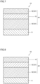
- Coating film 40 is disposed on substrate 11 ( Fig. 2 and Fig. 3 ).
- Fig. 2 is a schematic cross-sectional view showing an aspect of the cutting tool of the present disclosure.
- Fig. 3 is a schematic cross-sectional view showing another different aspect of the cutting tool of the present disclosure.
- “Coating film” covers at least the cutting edge of substrate 11, so that various properties such as peeling resistance, breakage resistance and abrasion resistance of a cutting tool are improved.
- the cutting edge described herein means a region within 500 ⁇ m from the cutting edge ridgeline along the substrate surface. It is preferable that coating film 40 cover whole the surface of substrate 11. However, the case where a part of substrate 11 is not covered with coating film 40, or the structure of coating film 40 is partly different is included within the scope of the present embodiment.
- the thickness of the coating film is preferably 0.1 ⁇ m or more and 30 ⁇ m or less, more preferably 0.4 ⁇ m or more and 20 ⁇ m or less, still more preferably 0.5 ⁇ m or more and 10 ⁇ m or less, furthermore preferably 0.7 ⁇ m or more and 5 ⁇ m or less, and particularly preferably 1 ⁇ m or more and 3 ⁇ m or less.
- the thickness of the coating film means the sum total of the respective thicknesses of the layers that constitute the coating film. Examples of the "layers that constitute the coating film" include the first layer, the second layer, and another layer that is described as a layer other than the first layer and the second layer in the following.
- the thickness of the coating film may be determined as follows. For example, the thicknesses are measured at five optional points of a cross-sectional sample in parallel with the normal direction of the surface of a substrate with a scanning electron microscope (SEM), and the average of the five measured thicknesses is determined as the thickness of the coating film.
- SEM scanning electron microscope
- a focused ion beam system, a cross section polisher, etc. may be used for the preparation of the cross-sectional samples.
- the measurement of each of the thickness of the first layer, the second layer, the first unit layer, the second unit layer, the third unit layer, the fourth unit layer and the other layers is performed in the same manner.
- the coating film includes a first layer and a second layer.
- a plurality of the first layers may be disposed as long as the effect that the cutting tool exhibits is maintained.
- a plurality of the second layers may be disposed as long as the effect that the cutting tool exhibits is maintained. Thereby, even when a part of the coating film is worn, the first layer and the second layer remain in the coating film, so that the cutting tool may retain the abrasion resistance, chipping resistance and peeling resistance of the coating film.
- Any one of the first layer and the second layer may be located nearest to the surface side. Also, any one of the first layer and the second layer may be located nearest to the substrate side.
- the expression "including the first layer and the second layer” means that the coating film may include another layer described in the following in addition to the first layer and the second layer.
- X-ray diffraction intensity I (200) of (200) plane means the diffraction intensity (height of peak) of the highest peak among X-ray diffraction peaks derived from (200) plane (hereinafter, also referred to as "maximum diffraction intensity"). As shown in Fig.
- X-ray diffraction intensity I (200) of (200) plane means the sum of the maximum diffraction intensity (height of peak). The same applies to "X-ray diffraction intensity I (111) of (111) plane", and "X-ray diffraction intensity I (220) of (220) plane”.
- At least one of I (200) /(I (200) +I (111) +I (220) ), I (111) /(I (200) +I (111) +I (220) ), and I (220) /(I (200) +I (111) +I (220) ), is preferably 0.47 or more, more preferably 0.50 or more, and still more preferably 0.55 or more.
- At least one of I (200) /(I (200) +I (111) +I (220) ), I (111) /(I (200) +I (111) +I (220) ), and I (220) /(I (200) +I (111) +I (220) ), is preferably 0.90 or less, more preferably 0.85 or less, and still more preferably 0.80 or less.
- At least one of I (200) /(I (200) +I (111) +I (220) ), I (111) /(I (200) +I (111) +I (220) ), and I (220) /(I (200) +I (111) +I (220) ), is preferably 0.47 or more and 0.90 or less, more preferably 0.50 or more and 0.85 or less, and still more preferably 0.55 or more and 0.80 or less.
- I (200) , I (111) and I (220) may be determined by X-ray diffraction measurement (XRD measurement), for example, under the following conditions. Specifically, I (200) , I (111) and I (220) may be obtained by irradiating X-ray to the surface of the coating film to perform X-ray diffraction measurement (XRD measurement). The X-ray diffraction intensity of each of (200) plane, (111) plane and (220) plane is determined to calculate I (200) , I (111) and I (220) . Examples of the apparatus for use in X-ray diffraction measurement include "SmartLab" (trade name) manufactured by Rigaku Corporation and "X'pert" (trade name) manufactured by PANalytical.
- the first layer of the present embodiment has a hardness H 1 of 25 GPa or more and 40 GPa or less.
- the lower limit of H 1 is preferably 27 GPa or more, more preferably 29 GPa or more, and still more preferably 31 GPa or more.
- the upper limit of H 1 is preferably 38 GPa or less, more preferably 36 GPa or less, and still more preferably 34 GPa or less.
- H 1 is preferably 27 GPa or more and 38 GPa or less, more preferably 29 GPa or more and 36 GPa or less, and still more preferably 31 GPa or more and 34 GPa or less.
- Hardness H 1 of the first layer is measured by a method in accordance with ISO14577 (2015) to measure the indentation hardness.
- a nanoindentation hardness tester (ENT1100a; manufactured by Elionix) is used as a measuring instrument. Specifically, first, the cutting tool is ground at the position where provided with the coating film so as to obtain a surface (inclined surface) having an inclination of 6° with respect to the surface direction of the outermost surface of the coating film.
- an indentation load controlled to have an indentation depth (h) of 1/10 or less of the film thickness of the first layer is applied under an environment at 25°C to 30°C, so that measurement by the nanoindentation method is performed.
- hardness H 1 of the first layer is calculated in accordance with ISO14577.
- Hardness H 2 of the second layer is measured in the same manner.
- hardness H 1 of the first layer means the hardness of the entire first layer.
- the first layer preferably has a thickness of 0.2 ⁇ m or more and 10 ⁇ m or less. Thereby, the abrasion resistance of the cutting tool may be further improved.
- the lower limit of the thickness of the first layer is preferably 0.4 ⁇ m or more, more preferably 0.5 ⁇ m or more, and still more preferably 0.6 ⁇ m or more.
- the upper limit of the thickness of the first layer is preferably 6 ⁇ m or less, more preferably 3 ⁇ m or less, and still more preferably 2 ⁇ m or less.
- the thickness of the first layer is preferably 0.4 ⁇ m or more and 6 ⁇ m or less, more preferably 0.5 ⁇ m or more and 3 ⁇ m or less, and still more preferably 0.6 ⁇ m or more and 2 ⁇ m or less.
- the first layer comprise a first unit layer, wherein the first unit layer is composed of Ti x Al y M 1-x-y C z N 1-z ;
- M is one element selected from the group consisting of zirconium, hafnium, group V elements and group VI elements of the periodic table, silicon, boron, and yttrium;
- x is 0.20 or more and 0.99 or less, y is 0.01 or more and 0.80 or less, 1-x-y is 0.01 or more and 0.20 or less, and z is 0 or more and 1.0 or less.
- the abrasion resistance of the cutting tool may be further improved.
- the expression "the first layer comprises a first unit layer” is a concept including an aspect in which the first layer consists of a first unit layer and an aspect in which the first layer comprises a second unit layer and a third unit layer to be described in the following together with the first unit layer.
- the expression "the first unit layer is composed of Ti x Al y M 1-x-y C z N 1-z " is a concept including not only an aspect in which the first unit layer is composed of Ti x Al y M 1-x-y C z N 1-z alone, but also an aspect in which the first unit layer comprises components other than Ti x Al y M 1-x-y C z N 1-z (for example, inevitable impurities) together with Ti x Al y M 1-x-y C z N 1-z , as long as the effect of the present disclosure is exhibited.
- x is preferably 0.25 or more and 0.95 or less, more preferably 0.30 or more and 0.90 or less, and still more preferably 0.35 or more and 0.80 or less.
- y is preferably 0.10 or more and 0.70 or less, more preferably 0.20 or more and 0.60 or less, and still more preferably 0.30 or more and 0.55 or less.
- 1-x-y is preferably 0.02 or more and 0.18 or less, more preferably 0.03 or more and 0.15 or less, and still more preferably 0.04 or more and 0.10 or less.
- z is preferably 0.01 or more and 0.90 or less, more preferably 0.05 or more and 0.70 or less, and still more preferably 0.10 or more and 0.50 or less.
- x may be 0.20 or more and 0.99 or less
- y may be 0.01 or more and 0.80 or less
- 1-x-y may be 0, and z may be 0 or more and 1.0 or less.
- 1-x-y is preferably not "0".
- x, y, and z may be checked by using an EDX (Energy Dispersive X-ray spectroscopy) apparatus attached to SEM or TEM. Specifically, first, a cutting tool is cut at an optional position in the film thickness direction to prepare a sample including a cross section of the coating film. Next, the first unit layer in the coating film is subjected to point analysis. The measurement point is on the middle point in the thickness direction of the first unit layer such that data near the interface are not included. The measurement is performed at five optionally selected points. At each of the five optional measurement points, x and y, which indicate the atomic ratio of each element, are specified. An average value of each of x and y at the five measurement points is determined. The average values correspond to x and y in the first unit layer. Note that m in the second unit layer described later, n in the third unit layer described later, and a, b, and c in the fourth unit layer described later are determined in the same manner.
- the thickness of the first unit layer is preferably 0.2 ⁇ m or more and 10 ⁇ m or less.
- the abrasion resistance of the cutting tool can be further improved.
- the lower limit of the thickness of the first unit layer is preferably 0.4 ⁇ m or more, more preferably 0.5 ⁇ m or more, and still more preferably 0.6 ⁇ m or more.
- the upper limit of the thickness of the first unit layer is preferably 6 ⁇ m or less, more preferably 3 ⁇ m or less, and still more preferably 2 ⁇ m or less.
- the thickness of the first unit layer is preferably 0.4 ⁇ m or more and 6 ⁇ m or less, more preferably 0.5 ⁇ m or more and 3 ⁇ m or less, and still more preferably 0.6 ⁇ m or more and 2 ⁇ m or less.
- the thickness of the first unit layer is preferably 0.005 ⁇ m or more and 1 ⁇ m or less. Thereby, the abrasion resistance of the cutting tool can be further improved.
- the lower limit of the thickness of the first unit layer is preferably 0.007 ⁇ m or more, more preferably 0.010 ⁇ m or more, and still more preferably 0.015 ⁇ m or more.
- the upper limit of the thickness of the first unit layer is preferably 0.8 ⁇ m or less, more preferably 0.6 ⁇ m or less, and still more preferably 0.3 ⁇ m or less.
- the thickness of the first unit layer is preferably 0.005 ⁇ m or more and 0.8 ⁇ m or less, more preferably 0.010 ⁇ m or more and 0.6 ⁇ m or less, and still more preferably 0.015 ⁇ m or more and 0.3 ⁇ m or less.
- first layer 12 further include a second unit layer 13 together with the first unit layer.
- second unit layer 13 is composed of Al m Cr 1-m N, m is 0 or more and 0.8 or less, and the thickness of a first unit layer 121 is 5 nm or more and 50 nm or less, and the thickness of a second unit layer 122 is 5 nm or more and 50 nm or less.
- first unit layer 121 and second unit layer 122 be alternately laminated ( Fig. 4 ). As a result, due to the fine grain size of the particles constituting the first layer, the hardness of the first layer increases, so that the abrasion resistance of the cutting tool may be further improved.
- any one of the first unit layer and the second unit layer may be disposed nearest to the substrate side, or any one of the first unit layer and the second unit layer may be disposed nearest to the surface side.
- the expression "the second unit layer is composed of Al m Cr 1-m N” is a concept not limited to an aspect in which the second unit layer is composed of Al m Cr 1-m N alone, but also includes an aspect in which the second unit layer includes components other than Al m C 1-m N (for example, inevitable impurities) together with Al m Cr 1-m N, as long as the effect of the present disclosure is exhibited.
- m is preferably 0.10 or more and 0.75 or less, more preferably 0.20 or more and 0.73 or less, and still more preferably 0.30 or more and 0.70 or less.
- the second unit layer preferably has a thickness of 5 nm or more and 1 ⁇ m or less. Thereby, the abrasion resistance of the cutting tool may be further improved.
- the lower limit of the thickness of the second unit layer is preferably 7 nm or more, more preferably 10 nm or more, and still more preferably 15 nm or more.
- the upper limit of the thickness of the second unit layer is preferably 0.8 ⁇ m or less, more preferably 0.6 ⁇ m or less, and still more preferably 0.3 ⁇ m or less.
- the thickness of the second unit layer is preferably 5 nm or more and 0.8 ⁇ m or less, more preferably 10 nm or more and 0.6 ⁇ m or less, and still more preferably 15 nm or more and 0.3 ⁇ m or less.
- first layer 12 further include a third unit layer 123 together with the first unit layer.
- third unit layer 123 is composed of Ti 1-n Al n N, wherein n is 0 or more and 0.8 or less, the thickness of first unit layer 121 is 5 nm or more and 50 nm or less, the thickness of third unit layer 123 is 5 nm or more and 50 nm or less. It is preferable that first unit layer 121 and third unit layer 123 be alternately laminated ( Fig. 5 ). As a result, due to the fine grain size of the particles constituting the first layer of the cutting tool, the hardness of the first layer increases, so that the abrasion resistance of the cutting tool may be further improved.
- any one of the first unit layer and the third unit layer may be disposed nearest to the substrate side, or any one of the first unit layer and the third unit layer may be disposed nearest to the surface side.
- the expression "the third unit layer is composed of Ti 1-n Al n N” is a concept not limited to an aspect in which the third unit layer is composed of Ti 1-n Al n N, but also includes an aspect in which the third unit layer includes components other than Ti 1-n Al n N (for example, inevitable impurities) together with Ti 1-n Al n N, as long as the effect of the present disclosure is exhibited.
- n is preferably 0.3 or more and 0.9 or less, more preferably 0.4 or more and 0.8 or less, and still more preferably 0.5 or more and 0.7 or less.
- the third unit layer preferably has a thickness of 5 nm or more and 1 ⁇ m or less. Thereby, the abrasion resistance of the cutting tool may be further improved.
- the lower limit of the thickness of the third unit layer is preferably 7 nm or more, more preferably 10 nm or more, and still more preferably 15 nm or more.
- the upper limit of the thickness of the third unit layer is preferably 0.8 ⁇ m or less, more preferably 0.6 ⁇ m or less, and still more preferably 0.3 ⁇ m or less.
- the thickness of the third unit layer is preferably 5 nm or more and 0.8 ⁇ m or less, more preferably 10 nm or more and 0.6 ⁇ m or less, and still more preferably 15 nm or more and 0.3 ⁇ m or less.
- the second layer of the present embodiment has a hardness H 2 which satisfies 0.5 ⁇ H 1 ⁇ H 2 ⁇ 0.9 ⁇ H 1 .
- Hardness H 2 preferably satisfies H 2 ⁇ 0.53 ⁇ H 1 , more preferably satisfies H 2 ⁇ 0.56 ⁇ H 1 , and still more preferably satisfies H 2 ⁇ 0.6 ⁇ H 1 .
- hardness H 2 preferably satisfies H 2 ⁇ 0.87 ⁇ H 1 , more preferably satisfies H 2 ⁇ 0.84 ⁇ H 1 , and still more preferably satisfies H 2 ⁇ 0.8 ⁇ H 1 .
- hardness H 2 preferably satisfies 0.53 ⁇ H 1 ⁇ H 2 ⁇ 0.87 ⁇ H 1 , more preferably satisfies 0.56 ⁇ H 1 ⁇ H 2 ⁇ 0.84 ⁇ H 1 , and still more preferably satisfies 0.6 ⁇ H 1 ⁇ H 2 ⁇ 0.8 ⁇ H 1 .
- the second layer preferably has a thickness of 0.2 ⁇ m or more and 10 ⁇ m or less. Thereby, the chipping resistance of the cutting tool and the peeling resistance of the cutting tool may be further improved.
- the lower limit of the thickness of the second layer is preferably 0.3 ⁇ m or more, more preferably 0.4 ⁇ m or more, and still more preferably 0.5 ⁇ m or more.
- the upper limit of the thickness of the second layer is preferably 8 ⁇ m or less, more preferably 5 ⁇ m or less, and still more preferably 3 ⁇ m or less.
- the thickness of the second layer is preferably 0.3 ⁇ m or more and 8 ⁇ m or less, more preferably 0.4 ⁇ m or more and 5 ⁇ m or less, and still more preferably 0.5 ⁇ m or more and 3 ⁇ m or less.
- the ratio T 1 /T 2 of thickness T 1 of the first layer to thickness T 2 of the second layer is preferably 0.02 or more and 50 or less. Thereby, the balance among abrasion resistance, peeling resistance, and chipping resistance can be improved, so that the life of the cutting tool can be further improved.
- the lower limit of T 1 /T 2 is preferably 0.04 or more, more preferably 0.06 or more, and still more preferably 0.1 or more.
- the upper limit of T 1 /T 2 is preferably 45 or less, more preferably 40 or less, and still more preferably 30 or less.
- the second layer preferably comprises the fourth unit layer.
- the fourth unit layer is composed of Ti a Al b C c N 1-c , wherein preferably a is 0.2 or more and 1.0 or less, b is 0 or more and 0.8 or less, and c is 0 or more and 1.0 or less.
- the expression “the second layer comprises the fourth unit layer” is a concept including an aspect in which the second layer consists of a fourth unit layer and an aspect in which the second layer comprises a layer other than the fourth unit layer together with the fourth unit layer.
- the expression “the fourth unit layer is composed of Ti a Al b C c N 1-c” is a concept including not only an aspect in which the fourth unit layer is composed of Ti a Al b C c N 1-c alone, but also an aspect in which the fourth unit layer comprises components other than Ti a Al b C c N 1-c together with Ti a Al b C c N 1-c , as long as the effect of the present disclosure is exhibited.
- the fourth unit layer preferably has a thickness of 0.3 ⁇ m or more and 9 ⁇ m or less. Thereby, the abrasion resistance of the cutting tool may be further improved.
- the lower limit of the thickness of the fourth unit layer is preferably 0.4 ⁇ m or more, more preferably 0.5 ⁇ m or more, and still more preferably 0.6 ⁇ m or more.
- the upper limit of the thickness of the fourth unit layer is preferably 7 ⁇ m or less, more preferably 5 ⁇ m or less, and still more preferably 3 ⁇ m or less.
- the thickness of the fourth unit layer is preferably 0.4 ⁇ m or more and 7 ⁇ m or less, more preferably 0.5 ⁇ m or more and 5 ⁇ m or less, and still more preferably 0.6 ⁇ m or more and 3 ⁇ m or less.
- a is preferably 0.3 or more and 0.95 or less, more preferably 0.35 or more and 0.9 or less, and still more preferably 0.4 or more and 0.85 or less.
- b is preferably 0.05 or more and 0.7 or less, more preferably 0.1 or more and 0.65 or less, and still more preferably 0.15 or more and 0.6 or less.
- c is preferably 0.01 or more and 0.9 or less, more preferably 0.03 or more and 0.85 or less, and still more preferably 0.05 or more and 0.7 or less.
- the coating film may further include other layers as long as the effects of the present embodiment are not impaired.
- examples of the other layers include a foundation layer 14, an intermediate layer 15, and a surface layer 16.
- the coating film of the present embodiment may include a foundation layer.
- Foundation layer 14 is a layer disposed between substrate 11 and any one of first layer 12 and second layer 13 disposed nearest to the substrate side.
- the foundation layer is composed of a first compound, and the first compound is preferably composed of one or more elements selected from the group consisting of group IV elements, group V elements and group VI elements of the periodic table and aluminum, and one or more elements selected from the group consisting of carbon, nitrogen, and boron and oxygen.
- the abrasion resistance of the cutting tool can be further improved. Further, thereby the adhesion between the coating film and the substrate can be also improved.
- the adhesion between the substrate and the coating film can be enhanced.
- the thickness of the foundation layer is preferably 0.1 ⁇ m or more and 20 ⁇ m or less. Thereby, the abrasion resistance of the cutting tool can be further improved. Thereby, the cutting tool can also have excellent breakage resistance.
- the coating film of the present embodiment may include an intermediate layer.
- An intermediate layer 15 is a layer disposed between first layer 12 and second layer 13. It is preferable that the composition of the intermediate layer be, for example, a TiAlN layer or a TiN layer. It is preferable that the thickness of the intermediate layer be 0.01 ⁇ m or more and 0.2 ⁇ m or less.
- the coating film of the present embodiment may include a surface layer.
- a surface layer 16 is a layer disposed nearest to the surface side in a coating film 40. However, the surface layer may not be formed at the cutting edge ridgeline.
- Surface layer 16 is composed of a second compound, and the second compound is preferably composed of one or more elements selected from the group consisting of group IV elements, group V elements and group VI elements of the periodic table and aluminum, and one or more elements selected from the group consisting of carbon, nitrogen, and boron and oxygen. Thereby, the abrasion resistance of the cutting tool can be further improved.
- Examples of surface layer 16 include a TiN layer and a TiAlN layer. Since the TiN layer has a distinct color (exhibiting golden color), when used as surface layer 16, identification of the corner of a cutting insert after use for cutting (identification of used portion) is advantageously easy. Use of the TiAlN layer as surface layer 16 allows the oxidation resistance of the coating film to be enhanced.
- the thickness of surface layer 16 be 0.05 ⁇ m or more and 1 ⁇ m or less. Thereby, the adhesion between surface layer 16 and a neighboring layer is enhanced.
- a method for manufacturing the cutting tool of embodiment 1 is described as follows. The following production method is an example, and the cutting tool in embodiment 1 may be produced by another method.
- the substrate is prepared.
- any substrate may be used as long as it is conventionally known as the substrate of this type.
- a tool having a shape according to ISO standard DNGA150408, made of cubic boron nitride sintered material, may be used.
- the second step includes "covering with first layer” for covering at least a part of the surface of the substrate and “covering with second layer” for covering at least a part of the surface of the substrate. As long as covering with first layer and covering with second layer are performed, any one of covering with first layer and second covering may be performed first. Further, the second step may further include at least any one of step (i), step (ii), and step (iii), which will be described later. In addition, the second step may further include "covering with another layer” of covering at least a part of the surface of the substrate with the other layer.
- covering with first layer and covering with second layer at least the cutting edge portion of the surface of the substrate is covered with the first layer or the second layer.
- the term "covering with the first layer” or “covering with the second layer” refers to a concept including both of the case where the substrate surface is covered with the first layer or the second layer directly on the surface, and the case where a layer (foundation layer) other than the first layer or the second layer is disposed between the substrate surface and the first layer or the second layer. Any one of covering with first layer and covering with second layer may be performed first.
- Covering with first layer may include a "step of covering with first unit layer” for forming a first unit layer in the first layer.
- Covering with first layer may further include a "step of covering with second unit layer” for forming a second unit layer in the first layer, or a “step of covering with third unit layer” for forming a third unit layer in the first layer.
- Covering with second layer may include a "step of covering with fourth unit layer” for forming a fourth unit layer in the second layer.
- the second step may include a "step of covering with another layer” for forming the other layer.
- Examples of the method for covering at least a part of the surface of the substrate with the first layer include a physical vapor deposition (PVD) method.
- PVD physical vapor deposition
- Examples of the physical vapor deposition method include sputtering, ion plating, arc ion plating method, and electron ion beam vapor deposition.
- use of cathode arc ion plating method having high ionization rate of a raw material element or sputtering is preferred, allowing the substrate surface to be subjected to metal or gas ion bombardment before forming the coating film, so that the adhesion between the coating film and the substrate is remarkedly improved.
- Examples of the conditions for forming a coating film by arc ion plating method include the following.
- a Ti target is used as metal evaporation source, and N 2 gas is used as reaction gas.
- the basal plate (substrate) temperature is set at 400 to 550°C and the gas pressure in the apparatus is set at 0.3 to 1.5 Pa.
- an arc current of 80 to 150 A is supplied to the cathode electrode to generate metal ions etc. from an arc-type evaporation source, so that a layer composed of TiN can be formed.
- a tungsten filament is also discharged during film formation (emission current: 30 to 45 A). Thereby, ions in the plasma can be increased.
- Examples of the apparatus used for arc ion plating method includes AIP (trade name) manufactured by Kobe Steel, Ltd.
- Examples of the conditions for forming a coating film by sputtering include the following.
- a Ti target can be used as metal evaporation source, and a sputtering gas such as N 2 gas, Ar gas, Kr gas, and Xe gas can be used as reaction gas.
- the present inventors have newly found that the difference in hardness between the first layer and the second layer can be adjusted by performing at least one of the following steps (i) to (iii).
- the difference in hardness between the first layer and the second layer can be easily adjusted by performing at least one of steps (i) to (iii).
- step (i) the second layer is annealed with a heater for a certain period of time.
- the rate of temperature increase in step (i) is, for example, 5°C/min or more and 10°C/min or less.
- the annealing temperature in step (i) is, for example, 400°C or more and 500°C or less.
- the annealing time in step (i) is, for example, 10 minutes or more and 60 minutes or less.
- the cooling rate in step (i) is, for example, 5°C/min or more and 10°C/min or less.
- the pressure in the furnace during cooling in step (i) is, for example, 1 Pa or more and 8 Pa or less.
- step (ii) the first layer or the second layer is subjected to ion bombardment using a sputtering gas.
- compressive stress can be imparted to the first layer or the second layer, so that the hardness of the first layer or the second layer treated with the ion bombardment can be increased.
- the gas composition in step (ii) is, for example, Ar (100%), Kr (100%), or Xe (100%).
- the gas pressure in step (ii) is, for example, 1 Pa or more and 3 Pa or less.
- the bias voltage in step (ii) is, for example, -1000 V or more and -600 V or less.
- the treatment time in step (ii) is, for example, 5 minutes or more and 60 minutes or less.
- step (iii) the first unit layer and the second unit layer or the third unit layer are alternately laminated. Thereby, lattice constant distortion occurs between layers having different compositions, so that the hardness of the first layer can be adjusted.
- step (iv) the bias voltage is adjusted as follows when covering with second layer and covering with first layer are switched.
- the bias voltage in covering with second layer is expressed as A (V) and the bias voltage in covering with first layer is expressed as B (V).
- a (V) the bias voltage in covering with first layer
- B (V) the bias voltage in covering with first layer
- the bias voltage set to A (V) covering with second layer is performed.
- the bias voltage is changed to more than A and less than B (V) when B>A, or changed to more than B and less than A (V) when A>B so as to perform film formation for 60 to 120 seconds.
- This step is represented as a step (iv-1).
- step (iv) includes one or both of step (iv-1) and step (iv-2).
- the bias voltage in covering with first layer is expressed as B (V) and the bias voltage in second covering is expressed as A (V).
- B (V) the bias voltage in covering with first layer
- a (V) the bias voltage in second covering
- the bias voltage set to B (V) covering with first layer is performed.
- the bias voltage is changed to more than A and less than B (V) when B>A, or changed to more than B and less than A (V) when A>B so as to perform film formation for 60 to 120 seconds.
- This step is represented as a step (iv-3).
- step (iv) includes one or both of step (iv-3) and step (iv-4).
- bias voltage B (V) in the step of covering with first layer is not in the range of more than 20 V and less than 60 V, a desired hardness H 1 tends to be hardly obtained.
- step (iv) changes in the bias voltage when switching from covering with first layer to covering with second layer and when switching from covering with second layer to covering with first layer can be moderated, so that variations in orientation in the coating film caused by abrupt changes in the bias voltage during film formation can be suppressed.
- one of the orientations becomes dominant, so that at least any one of I (200) /(I (200) +I (111) +I (220) ), I (111) /(I (200) +I (111) +I (220) ), and I (220) /(I (200) +I (111) +I (220) ) may be 0.45 or more.
- the present inventors have newly found that the variation in orientation in the coating film can be suppressed by switching the bias voltage as described above.
- the second step according to the present embodiment in addition to covering with first layer, covering with second layer, and the annealing step, "covering with foundation layer” for forming a foundation layer between the substrate and the first layer, "covering with intermediate layer” for forming an intermediate layer between the first layer and the second layer, "covering with surface layer” for forming a surface layer on the second layer, etc. may be appropriately performed.
- the other layers may be formed by conventional methods. Specifically, for example, the other layers may be formed by PVD method described above.
- a surface treatment step may be appropriately performed.
- the surface treatment step include surface treatment using a medium in which diamond powder is supported on an elastic material.
- a tool made of cubic boron nitride sintered material (shape: JIS standard DNGA150408) was prepared as a substrate. Subsequently, the substrate was set at a predetermined position of an arc ion plating apparatus (manufactured by Kobe Steel, Ltd., trade name: AIP).
- a second layer was formed on the surface of the substrate using an arc ion plating method under the conditions described in Table 1. Specifically, the following method was used.
- the metal evaporation source a target corresponding to the "composition" of the second layer described in the following Tables 3 and 4 was used.
- the composition of the second layer was TiAlN
- a TiAl target was used as the metal evaporation source.
- TiCN, TiC or TiN a Ti target was used as the metal evaporation source.
- N 2 gas and/or methane gas was used as the reaction gas.
- the basal plate (substrate) temperature was set at 500°C and the gas pressure in the apparatus was set at 1 Pa.
- step (i) the surface of the second layer was annealed under the conditions described in the column "Annealing Temperature [°C]/Time [minutes]” in Table 1.
- the furnace pressure during annealing was set to 2 Pa.
- “-" in the column “Annealing Temperature [°C]/Time [minutes]” means that step (i) was not performed.
- step (ii) ion bombardment was performed under the conditions described in the column “Ion bombardment” in Table 1.
- Ar (800 V) means that the reaction gas was Ar gas and the bias voltage was 800 V.
- the ion bombardment time was 45 minutes, and the furnace pressure was 1 Pa.
- “-" in the column “Ion bombardment” means that step (ii) was not performed.
- step (iv) while maintaining the conditions other than the bias voltage, the bias voltage was changed from the bias voltage value in covering with second layer to the bias voltage value described in the column "Step (iv)" in Table 1 so as to perform film formation for 60 seconds.
- the bias voltage was changed from 30 V (bias voltage in covering with second layer) to 33 V (bias voltage in step (iv)).
- the film formation conditions other than the bias voltage were changed to the following conditions for covering with first layer, and film formation was performed for 60 seconds while maintaining the bias voltage.
- the first layer was formed on the second layer.
- the metal evaporation source a target corresponding to the "composition" of the first layer described in the following Tables 3 and 4 was used.
- a TiAl target was used as the metal evaporation source.
- a TiAlSi target was used as the metal evaporation source.
- N 2 gas was used as the reaction gas.
- the basal plate (substrate) temperature was set at 500°C and the gas pressure in the apparatus was set at 4 Pa.
- a cutting tool of sample No. 1-16 was prepared using the following production method.
- the same substrate as that of sample No. 1-1 was prepared and set at a predetermined position in an arc ion plating apparatus.
- an arc ion plating method was used to form a first layer on the substrate. Specifically, the following method was used.
- the metal evaporation source a target corresponding to the "composition" of the first layer described in the following Tables 3 was used. In other words, a TiAl target was used as the metal evaporation source. N 2 gas was used as the reaction gas.
- the basal plate (substrate) temperature was set at 500°C and the gas pressure in the apparatus was set at 2 Pa.
- step (iv) while maintaining the conditions other than the bias voltage, the bias voltage was changed from the bias voltage value in covering with first layer to the bias voltage value described in the column "Step (iv)" in Table 2. Subsequently, the film formation conditions other than the bias voltage were changed to the following conditions for covering with second layer, and film formation was performed for 60 seconds while maintaining the bias voltage.
- the second layer was formed on the first layer.
- the metal evaporation source a target corresponding to the "composition" of the second layer described in the following Tables 3 and 4 was used.
- a TiAl target was used as the metal evaporation source.
- N 2 gas was used as the reaction gas.
- the basal plate (substrate) temperature was set at 500°C and the gas pressure in the apparatus was set at 2 Pa.
- steps (i) and (ii) were not performed to make the cutting tool of sample No. 1-16.
- Respective properties of cutting tools of samples No. 1-1 to No. 1-34 and samples No. 1-101 to No. 1-106 thus prepared were evaluated as follows. Cutting tools of samples No. 1-1 to No. 1-34 correspond to Examples, and cutting tools of samples No. 1-101 to No. 1-106 correspond to Comparative Examples.
- the thickness of the first layer was determined by the method described in embodiment 1. The results obtained are described in item “Thickness T 1 [ ⁇ m]” in Table 3 and Table 4, respectively. Further, with regard to the cutting tools of samples No. 1-1 to No. 1-34 and samples No. 1-101 to No. 1-106, the thickness of the second layer was determined by the method described in embodiment 1. The results obtained are described in item “Thickness T 2 [ ⁇ m]” in Table 3 and Table 4, respectively.
- hardness H 1 of the first layer was determined by the method described in embodiment 1. The results obtained are described in item “Hardness H 1 [GPa]” in Table 3 and Table 4, respectively. Further, with regard to the cutting tools of samples No. 1-1 to No. 1-34 and samples No. 1-101 to No. 1-106, hardness H 2 of the second layer was determined by the method described in embodiment 1. The results obtained are described in item “Hardness H 2 [GPa]” in Table 3 and Table 4, respectively.
- the cutting conditions correspond to high-load cutting of hardened steel (high-hardness materials).
- Samples No. 1-1 to No. 1-34 correspond to Examples. Samples No. 1-101 to No. 1-106 correspond to Comparative Examples. From the results in Table 3 and Table 4, it has been confirmed that the cutting tools of samples No. 1-1 to No. 1-34 corresponding to Examples have a longer tool life even in high-load cutting such as cutting of high-hardness materials such as hardened steel than the cutting tools of samples No. 1-101 to No. 1-106 corresponding to Comparative Examples. The reason for this is presumed as follows. In the cutting tools of samples No. 1-1 to No. 1-34, the first layer of the coating film has high hardness and good abrasion resistance, and the coating film includes the second layer together with the first layer, so that the coating film has good chipping resistance and peeling resistance. Thereby, the coating film is less likely to break during cutting, and the wear originating from there is suppressed.
- the same substrate as that in samples No. 1-1 to No. 1-15, samples No. 1-17 to No. 1-34, and samples No. 1-101 to No. 1-106 was prepared, and the substrate was set at a predetermined position of an arc ion plating apparatus.
- a second layer was formed on the surface of the substrate using arc ion plating method under the same conditions as in samples No. 1-1 to No. 1-15, samples No. 1-17 to No. 1-34, and samples No. 1-101 to No. 1-106 except that covering with second layer was performed under the conditions described in Tables 5 and 6 and the following targets were used as metal evaporation source.
- the metal evaporation source a target corresponding to the "composition" of the second layer described in the following Table 7 was used. Specifically, in the case where the composition of the second layer was TiAlN, a TiAl target was used as the metal evaporation source. In the case of TiCN or TiN, a Ti target was used as the metal evaporation source.
- step (iv) the bias voltage was changed from the bias voltage value in covering with second layer to the bias voltage value described in the column "Step (iv)" in Tables 5 and 6 so as to perform film formation for 60 seconds. Subsequently, the film formation conditions other than the bias voltage were changed to the following conditions for covering with first layer, and film formation was performed for 60 seconds while maintaining the bias voltage. The steps (i) and (ii) were not performed.
- the step of covering with first unit layer and the step of covering with second unit layer were alternately performed to form the first layer on the surface of the second layer.
- the metal evaporation source a target corresponding to the "composition" of the first layer described in the following Tables 7 and 8 was used.
- a TiAl target was used as the metal evaporation source.
- a TiAlSi target was used as the metal evaporation source.
- composition of the second unit layer was AlCrN
- an AlCr target was used as the metal evaporation source.
- a Cr target was used as the metal evaporation source.
- N 2 gas was used as the reaction gas.
- the basal plate (substrate) temperature was set at 500°C and the gas pressure in the apparatus was set at 4 Pa. From among the step of covering with first unit layer and the step of covering with second unit layer, the step of covering with first unit layer was performed first, and the step of covering with second unit layer was performed lastly.
- the results obtained are shown in Tables 7 and 8, respectively.
- the relationship among "thickness of first unit layer”, “thickness of second unit layer” and “thickness of first layer” is as follows.
- the first layer was formed by alternately laminating the first unit layers with a thickness of 15 nm and the second unit layers with a thickness of 10 nm, and the thickness T 1 of the first layer was 2.5 ⁇ m.
- the cutting tools of Samples No. 2-1 to No. 2-42 correspond to Examples.
- Samples No. 2-1 to No. 2-42 correspond to Examples. From the results in Table 7 and Table 8, it has been confirmed that the cutting tools of samples No. 2-1 to No. 2-42 corresponding to Examples have a long tool life even in high-load cutting such as cutting of high-hardness materials such as hardened steel. The reason for this is presumed as follows. As in Example 1, in the cutting tools of samples No. 2-1 to No. 2-42, the first layer of the coating film has high hardness and good abrasion resistance, and the coating film includes the second layer together with the first layer, so that the coating film has good chipping resistance and peeling resistance. Thereby, the coating film is less likely to break during cutting, and the wear originating from there is suppressed.
- the same substrate as that in samples No. 1-1 to No. 1-15, samples No. 1-17 to No. 1-34, and samples No. 1-101 to No. 1-106 was prepared, and the substrate was set at a predetermined position of an arc ion plating apparatus.
- a second layer was formed on the surface of the substrate using arc ion plating method under the same conditions as in samples No. 1-1 to No. 1-15, samples No. 1-17 to No. 1-34, and samples No. 1-101 to No. 1-106 except that covering with second layer was performed under the conditions described in Tables 9 and 10 and the following targets were used as metal evaporation source.
- the metal evaporation source a target corresponding to the "composition" of the second layer described in the following Tables 11 and 12 was used. Specifically, in the case where the composition of the second layer was TiAlN or TiAlC, a TiAl target was used as the metal evaporation source. In the case where the composition of the second layer was TiCN, TiC or TiN, a Ti target was used as the metal evaporation source.
- step (i) the surface of the second layer was annealed under the temperature conditions described in the column "Annealing Temperature [°C]" in Tables 9 and 10.
- “-" in the column “Annealing Temperature [°C]” means that step (i) was not performed.
- step (iv) the bias voltage in covering with second layer was adjusted to the bias voltage described in column “Step (iv)" in Tables 9 and 10 so as to perform film formation for 60 seconds. Subsequently, the film formation conditions other than the bias voltage were changed to the following conditions for covering with first layer, and film formation was performed for 60 seconds while maintaining the bias voltage. Step (ii) was not performed.
- covering with first layer using arc ion plating method under the conditions described in Tables 9 and 10, covering with first unit layer and covering with third unit layer were alternately performed to form the first layer on the surface of the second layer.
- the following method was used.
- the metal evaporation source a target corresponding to the "composition" of the first layer described in the following Tables 11 and 12 was used.
- a TiAl target was used as the metal evaporation source.
- a TiAlSi target was used as the metal evaporation source.
- the composition of the third unit layer was TiAlN
- a TiAl target was used as the metal evaporation source.
- N 2 gas was used as the reaction gas.
- the basal plate (substrate) temperature was set at 500°C and the gas pressure in the apparatus was set at 4 Pa. From among the step of covering with first unit layer and the step of covering with third unit layer, the step of covering with first unit layer was performed first, and the step of covering with third unit layer was performed lastly.
- the results obtained are shown in Tables 11 and 12, respectively.
- the relationship among "thickness of first unit layer”, "thickness of third unit layer” and “thickness of first layer” is as follows.
- the first layer was formed by alternately laminating the first unit layers with a thickness of 10 nm and the third unit layers with a thickness of 15 nm, and the thickness T 1 of the first layer was 2.5 ⁇ m.
- the cutting tools of samples No. 3-1 to No. 3-43 correspond to Examples, and the cutting tool of sample No. 3-101 correspond to Comparative Example.
- Samples No. 3-1 to No. 3-43 correspond to Examples. Also, sample No. 3-101 corresponds to Comparative Example. From the results in Table 11 and Table 12, it has been confirmed that the cutting tools of samples No. 3-1 to No. 3-43 corresponding to Examples have a longer tool life even in high-load cutting such as cutting of high-hardness materials such as hardened steel than sample No. 3-101 corresponding to Comparative Example. The reason for this is presumed as follows. As in Example 1, in the cutting tools of samples No. 3-1 to No. 3-43, the first layer of the coating film has high hardness and good abrasion resistance, and the coating film includes the second layer together with the first layer, so that the coating film has good chipping resistance and peeling resistance. Thereby, the coating film is less likely to break during cutting, and the wear originating from there is suppressed.
- the same substrate as that in samples No. 1-1 to No. 1-15, samples No. 1-17 to No. 1-34, and samples No. 1-101 to No. 1-106 was prepared, and the substrate was set at a predetermined position of an arc ion plating apparatus.
- a second layer was formed on the surface of the substrate using arc ion plating method under the same conditions as in samples No. 1-1 to No. 1-15, samples No. 1-17 to No. 1-34, and samples No. 1-101 to No. 1-106 except that covering with second layer was performed under the conditions described in Table 13 and the following targets were used as metal evaporation source.
- the metal evaporation source a target corresponding to the "composition" of the second layer described in the following Table 14 was used. Specifically, in the case where the composition of the second layer was TiAlN or TiAlC, a Ti target and an Al target were used as the metal evaporation source. In the case where the composition of the second layer was TiCN or TiN, a Ti target was used as the metal evaporation source.
- step (iv) the bias voltage was changed from the bias voltage value in covering with second layer to the bias voltage value described in column "step (iv)" in Table 13 so as to perform film formation for 60 seconds. Subsequently, the film formation conditions other than the bias voltage were changed to the following conditions for covering with first layer, and film formation was performed for 60 seconds while maintaining the bias voltage. Steps (i) and (ii) were not performed.
- the step of covering with first unit layer and the step of covering with second unit layer were alternately performed to form the first layer on the surface of the second layer.
- the metal evaporation source a target corresponding to the "composition" of the first layer described in the following Table 14 was used.
- a TiAl target was used as the metal evaporation source.
- a TiAlSi target was used as the metal evaporation source.
- composition of the second unit layer was AlCrN
- an AlCr target was used as the metal evaporation source.
- a Cr target was used as the metal evaporation source.
- N 2 gas was used as the reaction gas.
- the basal plate (substrate) temperature was set at 500°C and the gas pressure in the apparatus was set at 4 Pa. From among the step of covering with first unit layer and the step of covering with second unit layer, the step of covering with first unit layer was performed first, and the step of covering with second unit layer was performed lastly.
- the series of steps composed of covering with second layer to covering with first layer was repeated the number of times described in the item "Number of repetitions of covering with second layer to covering with first layer" in Table 13.
- the series of steps composed of covering with second layer to covering with first layer was repeated three times.
- the second layers and the first layers are alternately laminated and three layers each of the second layers and the first layers are included.
- the first layer was formed by alternately laminating the first unit layers with a thickness of 15 nm and the second unit layers with a thickness of 10 nm, and the thickness T 1 of the first layer was 0.5 ⁇ m.
- the coating film there exist three layers of the first layers and three layers of the second layers having a thickness T 2 of 0.5 ⁇ m.
- the cutting tools of samples No. 4-1 to No. 4-28 correspond to Examples.
- Samples No. 4-1 to No. 4-28 correspond to Examples. From the results in Table 14, it has been confirmed that the cutting tools of samples No. 4-1 to No. 4-28 corresponding to Examples have a long tool life even in high-load cutting such as cutting of high-hardness materials such as hardened steel. The reason for this is presumed as follows. As in Example 1, in the cutting tools of samples No. 4-1 to No. 4-28, the first layer of the coating film has high hardness and good abrasion resistance, and the coating film includes the second layer together with the first layer, so that the coating film has good chipping resistance and peeling resistance. Thereby, the coating film is less likely to break during cutting, and the wear originating from there is suppressed.
- the same substrate as that in samples No. 1-1 to No. 1-15, samples No. 1-17 to No. 1-34, and samples No. 1-101 to No. 1-106 was prepared, and the substrate was set at a predetermined position of an arc ion plating apparatus.
- a second layer was formed on the surface of the substrate using arc ion plating method under the same conditions as in samples No. 1-1 to No. 1-15, samples No. 1-17 to No. 1-34, and samples No. 1-101 to No. 1-106 except that covering with second layer was performed under the conditions described in Table 15 and the following targets were used as metal evaporation source.
- the metal evaporation source a target corresponding to the "composition" of the second layer described in the following Table 16 was used. Specifically, in the case where the composition of the second layer was TiAlN or TiAlC, a TiAl target was used as the metal evaporation source. In the case where the composition of the second layer was TiN, a Ti target was used as the metal evaporation source.
- step (iv) the bias voltage was changed from the bias voltage value in covering with second layer to the bias voltage value described in column "Step (iv)" in Table 15 so as to perform film formation for 60 seconds. Subsequently, the film formation conditions other than the bias voltage were changed to the following conditions for covering with first layer, and film formation was performed for 60 seconds while maintaining the bias voltage. Steps (i) and (ii) were not performed.
- the step of covering with first unit layer and the step of covering with third unit layer were alternately performed to form the first layer on the surface of the second layer.
- the metal evaporation source a target corresponding to the "composition" of the first layer described in the following Table 16 was used.
- a TiAl target was used as the metal evaporation source.
- a TiAlSi target was used as the metal evaporation source.
- the composition of the third unit layer was TiAlN
- a TiAl target was used as the metal evaporation source.
- an Al target was used as the metal evaporation source.
- N 2 gas was used as the reaction gas.
- the basal plate (substrate) temperature was set at 500°C and the gas pressure in the apparatus was set at 4 Pa. From among the step of covering with first unit layer and the step of covering with second unit layer, the step of covering with first unit layer was performed first, and the step of covering with third unit layer was performed lastly.
- step (iii) the series of steps composed of covering with second layer to covering with first layer was repeated the number of times described in the item "Number of repetitions of step of covering with second layer to step of covering first layer" in Table 15.
- the series of steps composed of covering with second layer to covering with first layer was repeated three times.
- the second layers and the first layers are alternately laminated and three layers each of the second layers and the first layers are included.
- the first layer was formed by alternately laminating the first unit layers with a thickness of 10 nm and the second unit layers with a thickness of 15 nm, and the thickness T 1 of the first layer was 0.5 ⁇ m.
- the coating film there exist three layers of the first layers and three layers of the second layer having a thickness T 2 of 0.5 ⁇ m.
- the cutting tools of samples No. 5-1 to No. 5-28 correspond to Examples.
- Samples No. 5-1 to No. 5-28 correspond to Examples. From the results in Table 16, it has been confirmed that the cutting tools of samples No. 5-1 to No. 5-28 corresponding to Examples have a long tool life even in high-load cutting such as cutting of high-hardness materials such as hardened steel. The reason for this is presumed as follows.
- the first layer of the coating film has high hardness and good abrasion resistance
- the coating film includes the second layer together with the first layer, so that the coating film has good chipping resistance and peeling resistance. Thereby, the coating film is less likely to break during cutting, and the wear originating from there is suppressed.
Landscapes
- Chemical & Material Sciences (AREA)
- Mechanical Engineering (AREA)
- Engineering & Computer Science (AREA)
- Organic Chemistry (AREA)
- Materials Engineering (AREA)
- Metallurgy (AREA)
- Chemical Kinetics & Catalysis (AREA)
- Inorganic Chemistry (AREA)
- Health & Medical Sciences (AREA)
- Toxicology (AREA)
- Cutting Tools, Boring Holders, And Turrets (AREA)
- Drilling Tools (AREA)
- Physical Vapour Deposition (AREA)
Applications Claiming Priority (2)
| Application Number | Priority Date | Filing Date | Title |
|---|---|---|---|
| PCT/JP2021/024828 WO2023276066A1 (ja) | 2021-06-30 | 2021-06-30 | 切削工具 |
| PCT/JP2022/026003 WO2023277077A1 (ja) | 2021-06-30 | 2022-06-29 | 切削工具 |
Publications (2)
| Publication Number | Publication Date |
|---|---|
| EP4365330A4 EP4365330A4 (en) | 2024-05-08 |
| EP4365330A1 true EP4365330A1 (en) | 2024-05-08 |
Family
ID=84691684
Family Applications (1)
| Application Number | Title | Priority Date | Filing Date |
|---|---|---|---|
| EP22833223.5A Pending EP4365330A1 (en) | 2021-06-30 | 2022-06-29 | Cutting tool |
Country Status (6)
| Country | Link |
|---|---|
| US (1) | US12383963B2 (https=) |
| EP (1) | EP4365330A1 (https=) |
| JP (1) | JP7355293B2 (https=) |
| KR (1) | KR20240026951A (https=) |
| CN (1) | CN117580664A (https=) |
| WO (2) | WO2023276066A1 (https=) |
Families Citing this family (3)
| Publication number | Priority date | Publication date | Assignee | Title |
|---|---|---|---|---|
| CN121038919A (zh) * | 2023-04-28 | 2025-11-28 | 住友电工硬质合金株式会社 | 切削工具 |
| WO2025022602A1 (ja) * | 2023-07-26 | 2025-01-30 | 住友電工ハードメタル株式会社 | 切削工具 |
| WO2026075029A1 (ja) * | 2024-10-01 | 2026-04-09 | 三菱マテリアル株式会社 | 表面被覆切削工具 |
Family Cites Families (16)
| Publication number | Priority date | Publication date | Assignee | Title |
|---|---|---|---|---|
| JP3934263B2 (ja) * | 1998-10-27 | 2007-06-20 | 三菱マテリアル神戸ツールズ株式会社 | 耐摩耗性に優れた硬質皮膜および硬質皮膜被覆部材 |
| JP3637883B2 (ja) * | 2000-08-31 | 2005-04-13 | 住友電気工業株式会社 | 表面被覆窒化硼素焼結体工具 |
| JP3404012B2 (ja) * | 2000-09-19 | 2003-05-06 | 日立ツール株式会社 | 硬質皮膜被覆工具 |
| JP4062582B2 (ja) * | 2001-07-23 | 2008-03-19 | 株式会社神戸製鋼所 | 切削工具用硬質皮膜およびその製造方法並びに硬質皮膜形成用ターゲット |
| JP4132931B2 (ja) * | 2002-04-11 | 2008-08-13 | 株式会社神戸製鋼所 | 硬質皮膜被覆工具およびその製造方法 |
| JP2005138211A (ja) * | 2003-11-05 | 2005-06-02 | Sumitomo Electric Hardmetal Corp | 表面被覆切削工具 |
| JP4707541B2 (ja) * | 2005-03-24 | 2011-06-22 | 日立ツール株式会社 | 硬質皮膜被覆部材 |
| JP2008279562A (ja) * | 2007-05-11 | 2008-11-20 | Sumitomo Electric Ind Ltd | 表面被覆切削工具 |
| JP2009148856A (ja) * | 2007-12-20 | 2009-07-09 | Sumitomo Electric Ind Ltd | 表面被覆切削工具 |
| JP2010284787A (ja) * | 2009-06-15 | 2010-12-24 | Hitachi Tool Engineering Ltd | 硬質皮膜被覆切削工具 |
| JP2012045650A (ja) | 2010-08-25 | 2012-03-08 | Hitachi Tool Engineering Ltd | 硬質皮膜被覆切削工具 |
| KR101284766B1 (ko) * | 2011-11-30 | 2013-07-17 | 한국야금 주식회사 | 절삭공구용 경질피막 |
| JP6634647B2 (ja) * | 2014-11-27 | 2020-01-22 | 三菱マテリアル株式会社 | 耐チッピング性、耐摩耗性にすぐれた表面被覆切削工具 |
| CN108472749B (zh) | 2015-12-22 | 2020-01-17 | 京瓷株式会社 | 覆盖工具 |
| EP3441168A4 (en) * | 2016-04-07 | 2020-03-18 | Tungaloy Corporation | COATED CUTTING TOOL |
| JP2018069433A (ja) | 2016-11-04 | 2018-05-10 | 住友電気工業株式会社 | 表面被覆切削工具 |
-
2021
- 2021-06-30 WO PCT/JP2021/024828 patent/WO2023276066A1/ja not_active Ceased
-
2022
- 2022-06-29 WO PCT/JP2022/026003 patent/WO2023277077A1/ja not_active Ceased
- 2022-06-29 US US18/575,320 patent/US12383963B2/en active Active
- 2022-06-29 EP EP22833223.5A patent/EP4365330A1/en active Pending
- 2022-06-29 CN CN202280045932.0A patent/CN117580664A/zh active Pending
- 2022-06-29 KR KR1020237044935A patent/KR20240026951A/ko active Pending
- 2022-06-29 JP JP2023518445A patent/JP7355293B2/ja active Active
Also Published As
| Publication number | Publication date |
|---|---|
| US12383963B2 (en) | 2025-08-12 |
| WO2023277077A1 (ja) | 2023-01-05 |
| EP4365330A4 (en) | 2024-05-08 |
| KR20240026951A (ko) | 2024-02-29 |
| WO2023276066A1 (ja) | 2023-01-05 |
| US20240261868A1 (en) | 2024-08-08 |
| CN117580664A (zh) | 2024-02-20 |
| JPWO2023277077A1 (https=) | 2023-01-05 |
| JP7355293B2 (ja) | 2023-10-03 |
Similar Documents
| Publication | Publication Date | Title |
|---|---|---|
| EP4365330A1 (en) | Cutting tool | |
| EP3153259B1 (en) | Surface-coated tool and method for manufacturing same | |
| EP3173169B1 (en) | Coated cutting tool | |
| EP3444053B1 (en) | Surface-coated cutting tool and manufacturing method therefor | |
| EP3269479A1 (en) | Surface-coated cutting tool and manufacturing method therefor | |
| EP3950190B1 (en) | Cutting tool | |
| EP3808477B1 (en) | Surface-coated cutting tool and process for producing same | |
| EP4215302B1 (en) | Cutting tool | |
| EP3769882A1 (en) | Surface-coated cutting tool | |
| EP3769880A1 (en) | Surface-coated cutting tool | |
| EP3960341A1 (en) | Cutting tool | |
| EP4494788B1 (en) | Cutting tool | |
| EP3769877A1 (en) | Surface-coated cutting tool | |
| EP4306246A1 (en) | Cutting tool | |
| EP4088842B1 (en) | Cutting tool | |
| US12350742B2 (en) | Surface-coated cutting tool | |
| JP7745161B2 (ja) | 表面被覆切削工具 | |
| EP4091745B1 (en) | Cutting tool | |
| EP4088840A1 (en) | Cutting tool | |
| EP3564404B1 (en) | Coating | |
| EP4678315A1 (en) | Surface-coated cutting tool | |
| JP7745160B2 (ja) | 表面被覆切削工具 | |
| EP4364875A1 (en) | Cutting tool | |
| JP2022030401A (ja) | 表面被覆切削工具 |
Legal Events
| Date | Code | Title | Description |
|---|---|---|---|
| STAA | Information on the status of an ep patent application or granted ep patent |
Free format text: STATUS: THE INTERNATIONAL PUBLICATION HAS BEEN MADE |
|
| PUAI | Public reference made under article 153(3) epc to a published international application that has entered the european phase |
Free format text: ORIGINAL CODE: 0009012 |
|
| STAA | Information on the status of an ep patent application or granted ep patent |
Free format text: STATUS: REQUEST FOR EXAMINATION WAS MADE |
|
| 17P | Request for examination filed |
Effective date: 20231227 |
|
| A4 | Supplementary search report drawn up and despatched |
Effective date: 20240222 |
|
| AK | Designated contracting states |
Kind code of ref document: A1 Designated state(s): AL AT BE BG CH CY CZ DE DK EE ES FI FR GB GR HR HU IE IS IT LI LT LU LV MC MK MT NL NO PL PT RO RS SE SI SK SM TR |
|
| DAV | Request for validation of the european patent (deleted) | ||
| DAX | Request for extension of the european patent (deleted) |