EP4359609B1 - Verfahren und system zur korrektur von vertikalen lagefehlern eines gleises - Google Patents
Verfahren und system zur korrektur von vertikalen lagefehlern eines gleises Download PDFInfo
- Publication number
- EP4359609B1 EP4359609B1 EP22733082.6A EP22733082A EP4359609B1 EP 4359609 B1 EP4359609 B1 EP 4359609B1 EP 22733082 A EP22733082 A EP 22733082A EP 4359609 B1 EP4359609 B1 EP 4359609B1
- Authority
- EP
- European Patent Office
- Prior art keywords
- track
- measuring
- track position
- stabilizer
- position data
- Prior art date
- Legal status (The legal status is an assumption and is not a legal conclusion. Google has not performed a legal analysis and makes no representation as to the accuracy of the status listed.)
- Active
Links
Images

Classifications
-
- E—FIXED CONSTRUCTIONS
- E01—CONSTRUCTION OF ROADS, RAILWAYS, OR BRIDGES
- E01B—PERMANENT WAY; PERMANENT-WAY TOOLS; MACHINES FOR MAKING RAILWAYS OF ALL KINDS
- E01B27/00—Placing, renewing, working, cleaning, or taking-up the ballast, with or without concurrent work on the track; Devices therefor; Packing sleepers
- E01B27/12—Packing sleepers, with or without concurrent work on the track; Compacting track-carrying ballast
- E01B27/13—Packing sleepers, with or without concurrent work on the track
- E01B27/16—Sleeper-tamping machines
- E01B27/17—Sleeper-tamping machines combined with means for lifting, levelling or slewing the track
-
- E—FIXED CONSTRUCTIONS
- E01—CONSTRUCTION OF ROADS, RAILWAYS, OR BRIDGES
- E01B—PERMANENT WAY; PERMANENT-WAY TOOLS; MACHINES FOR MAKING RAILWAYS OF ALL KINDS
- E01B27/00—Placing, renewing, working, cleaning, or taking-up the ballast, with or without concurrent work on the track; Devices therefor; Packing sleepers
- E01B27/12—Packing sleepers, with or without concurrent work on the track; Compacting track-carrying ballast
- E01B27/20—Compacting the material of the track-carrying ballastway, e.g. by vibrating the track, by surface vibrators
-
- E—FIXED CONSTRUCTIONS
- E01—CONSTRUCTION OF ROADS, RAILWAYS, OR BRIDGES
- E01B—PERMANENT WAY; PERMANENT-WAY TOOLS; MACHINES FOR MAKING RAILWAYS OF ALL KINDS
- E01B35/00—Applications of measuring apparatus or devices for track-building purposes
-
- E—FIXED CONSTRUCTIONS
- E01—CONSTRUCTION OF ROADS, RAILWAYS, OR BRIDGES
- E01B—PERMANENT WAY; PERMANENT-WAY TOOLS; MACHINES FOR MAKING RAILWAYS OF ALL KINDS
- E01B2203/00—Devices for working the railway-superstructure
- E01B2203/10—Track-lifting or-lining devices or methods
-
- E—FIXED CONSTRUCTIONS
- E01—CONSTRUCTION OF ROADS, RAILWAYS, OR BRIDGES
- E01B—PERMANENT WAY; PERMANENT-WAY TOOLS; MACHINES FOR MAKING RAILWAYS OF ALL KINDS
- E01B2203/00—Devices for working the railway-superstructure
- E01B2203/16—Guiding or measuring means, e.g. for alignment, canting, stepwise propagation
-
- E—FIXED CONSTRUCTIONS
- E01—CONSTRUCTION OF ROADS, RAILWAYS, OR BRIDGES
- E01B—PERMANENT WAY; PERMANENT-WAY TOOLS; MACHINES FOR MAKING RAILWAYS OF ALL KINDS
- E01B29/00—Laying, rebuilding, or taking-up tracks; Tools or machines therefor
- E01B29/04—Lifting or levelling of tracks
-
- E—FIXED CONSTRUCTIONS
- E01—CONSTRUCTION OF ROADS, RAILWAYS, OR BRIDGES
- E01B—PERMANENT WAY; PERMANENT-WAY TOOLS; MACHINES FOR MAKING RAILWAYS OF ALL KINDS
- E01B35/00—Applications of measuring apparatus or devices for track-building purposes
- E01B35/06—Applications of measuring apparatus or devices for track-building purposes for measuring irregularities in longitudinal direction
- E01B35/08—Applications of measuring apparatus or devices for track-building purposes for measuring irregularities in longitudinal direction for levelling
Definitions
- a targeted elevation of the track is specified in relation to the elevation errors, allowing track sections with larger elevation errors to be more strongly compacted during subsequent track stabilization. This is intended to counteract rapid subsidence due to traffic loads into the old, faulty track geometry.
- the AT 519317 A1 discloses a modified method in which, prior to a lifting and tamping process, a smoothed actual track position profile is created from the actual track position of the untreated track.
- the respective overlift value is subsequently specified based on this actual track position profile with respect to the approximately smoothed actual track position profile.
- this method only short-wave track geometry errors are processed with an overlift value. Long-wave settlements are ignored when specifying the overlift value.
- EP 0 952 254 A1 Another method for track position correction using a dynamic track stabilizer is described by EP 0 952 254 A1
- the track stabilizer is operated with a variable static load to eliminate long-wave track position errors after a lifting and tamping process. Based on a measurement of the tamped track, a new target track position is calculated, with correction values derived from this data determining the change in the static load.
- a similar procedure is known from WO 2020/177967 A1 known, whereby by removing ballast from the front sides of the track sleepers by means of a respective lateral clearing device, an increased lowering of the track can be achieved by a dynamic track stabilizer.
- the invention is based on the object of improving a method of the type mentioned above over the prior art in such a way that, after the stabilization process, an optimal track position is achieved regardless of the type and extent of existing track defects. Furthermore, it is an object of the invention to provide a corresponding system.
- additional track position data of the stabilized, lowered track outside the sphere of influence of the stabilization unit whereby the dynamic track stabilizer is controlled during the stabilization process depending on the track position data of the untreated and tamped track at the work station and on the track position data of the stabilized, lowered track at the final measurement point.
- the additional final measurement of the track position after the stabilization process enables precise control of the dynamic track stabilizer.
- the track position measured before and after the lifting and tamping process, together with the track position measured after the stabilization process is used as the basis for the controlled control of the dynamic track stabilizer. In this way, remaining residual errors approach zero after an initial transient phase, resulting in an optimal track position. Residual errors recorded after the lifting and tamping process, in particular, are eliminated with the controlled control of the dynamic track stabilizer.
- track position data for a final target position of the track are specified, whereby the dynamic track stabilizer is additionally controlled during the stabilization process depending on correction data derived for the work location from the target position data and the track position data of the untreated track.
- measurement data from individual errors and other pronounced position errors of the untreated track are directly incorporated into the control of the dynamic track stabilizer, thereby proactively minimizing control deviations.
- This process extension in particular, actively compensates for uneven overlifts through the upstream lifting and tamping process with design overlift.
- a longitudinal inclination or longitudinal height and a transverse inclination or superelevation of the track are advantageously measured at each measuring point.
- the longitudinal inclination or longitudinal height of an inner rail is preferably recorded.
- the transverse inclination or superelevation indicates the position of an outer rail.
- the vertical positions (height positions) of both rails of the track in different processing states are recorded as track position data.
- At least one of the following operating parameters of the dynamic track stabilizer is changed during the stabilization process depending on the recorded track position data: an oscillation frequency of the stabilization unit, a travel speed of the dynamic track stabilizer, a load of the stabilization unit acting on a left rail of the track, a load of the stabilization unit acting on a right rail of the track and a total load acting from the stabilization unit on the track.
- the stabilization process is logically initiated with a predefined initial value for the respective operating parameter, with an adjusted value being continuously calculated for the respective operating parameter during the stabilization process using an algorithm implemented in a computing unit.
- the continuous recalculation of the variable operating parameter results in an immediate adaptation of the stabilization process to various system-specific or external influences.
- weighting factors are stored in the algorithm for the respective operating parameter, with the weighting factors being continuously adjusted by means of a control system.
- a formula with its own weighting factors is implemented in the computing unit for each variable operating parameter.
- the controlled activation of the dynamic track stabilizer is then achieved simply by continuously adjusting the weighting factors.
- Each operating parameter formula maps the specific interaction between the respective operating parameter and the recorded track position data.
- a stored adjustment logic for the weighting factors determines the control dynamics.
- a track position measuring system comprising several measuring devices is carried along with the dynamic track stabilizer, whereby at the respective measuring point the corresponding track position is recorded with respect to a common reference system.
- the track position data of the changing track position during processing is collected while the dynamic track stabilizer advances.
- a track section under consideration is initially located in front of the stabilization unit, where the track position is recorded after the lifting and tamping process.
- the dynamic track stabilizer advances, the same track section becomes the current work point during the controlled lowering of the track by the stabilization unit, with a measuring point immediately behind it.
- this measuring point is preferably located between two stabilization unit units. Outside the sphere of influence of the stabilization unit, the track position data of the lowered track position is recorded at the final measuring point.
- the respective measuring point corresponds to a track section under consideration in a chronological sequence during a work advance.
- the reference system is formed by means of a camera attached to one of the measuring devices and a reference mark attached to another measuring device and positioned within the camera's recording area.
- the camera records measurement marks attached to the remaining measuring devices.
- Such an optical measuring system delivers precise measurement results for multiple measuring points, with the shared reference system simplifying further processing of the acquired track position data.
- a reference mark is attached directly to the stabilization unit. The corresponding measuring point thus coincides with the work site. The vibration amplitudes of the stabilization unit are then also recorded using the camera. This additional measured variable can be used as an additional parameter for controlling the stabilization process.
- the system according to the invention for carrying out one of the described methods comprises a track position measuring system and a dynamic track stabilizer with a stabilization unit for correcting vertical position errors at a forward moving work point of a track, wherein the track position measuring system is set up to record the track position at a measuring point upstream of the dynamic track stabilizer in the working direction and at a final measuring point downstream of the dynamic track stabilizer in the working direction and located outside the sphere of influence of the stabilization unit, wherein the dynamic track stabilizer comprises a control device to which track position data recorded by means of the track position measuring system are fed and wherein the control device is set up to control the dynamic track stabilizer as a function of track position data assigned to the working point and track position data of the stabilized, lowered track assigned to the final measuring point outside the sphere of influence of the stabilization unit.
- control device comprises a computing unit in which an algorithm for recalculating at least one operating parameter of the dynamic track stabilizer is implemented based on continuously updated track position data.
- detected track position errors lead to an adjustment of the control of the dynamic track stabilizer almost in real time.
- the short response time results in a further improvement in the quality of the corrected track position.
- the distance between the work site and the final measurement point is advantageously between 3 m and 10 m, especially between 5 m and 8 m. This ensures that an undisturbed actual track position is determined at the final measurement point after the stabilization process. In this way, the final measurement provides particularly precise data for a control loop for controlling the dynamic track stabilizer.
- the final measurement point follows the work site at a sufficiently close distance to allow rapid control adjustments to be made if necessary.
- the stabilization unit comprises a vibration generator and roller clamps that can be clamped to the track rails.
- the stabilization unit is supported against a machine frame by separately controllable load drives. With this improvement, a left and a right rail of the track Different loads can be applied. This allows for precise adjustment of the depressions achieved with the stabilization unit, so that the specified transverse slope or superelevation of the track is precisely achieved.
- An advantageous extension of the system relates to a machine network in which a tamping machine is arranged directly upstream of the dynamic track stabilizer in the working direction, and wherein the track position measuring system comprises at least one measuring device assigned to the tamping machine.
- the track position measuring system comprises at least one measuring device assigned to the tamping machine.
- the track position measuring system comprises a first measuring device to which a camera is mounted, a second measuring device having a reference mark mounted on it, and at least one further measuring device with a reference mark mounted between the first and second measuring devices.
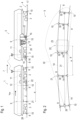
- the tamping machine 5 and the dynamic track stabilizer 1 form a combined track maintenance machine.
- the cyclical forward movement of a tamping unit 6 is adapted to the continuous forward movement of the dynamic track stabilizer 1, for example, via a longitudinally displaceable auxiliary frame (satellite).
- a measuring system 9 with measuring chords is assigned to the tamping machine 1 as a reference system.
- the dynamic track stabilizer 1 comprises another measuring system 9 with its own measuring chords.
- these two measuring systems 9 are combined into a common track position measuring system 9.
- all recorded track position data is processed by a common evaluation device 11. If necessary, data is transmitted between the tamping machine 5 and the dynamic track stabilizer 1 via an air interface.
- the tamping machine 5 comprises a lifting unit 16, which is arranged in front of the tamping unit 6. In between is a further measuring device 8 for recording the lifting 17 that has been carried out.
- tamping picks of the tamping unit 6 penetrate the ballast bed 15. Under vibration, a setting movement occurs in which ballast is pushed under the raised sleepers 13 and compacted. In this way, the track 4 is temporarily fixed in a raised track position.
- each measuring device 8 is designed as a rail-guided device.
- the respective device 8 comprises flanged rollers pressed against the inner sides of the rails 14 by means of a spreading axis.
- a non-contact variant of the respective measuring device 8 comprises a support on which measuring sensors (e.g., laser scanners) directed against the rails 14 are arranged. These sensors detect the position of the measuring device 8 relative to the rails 14.
- a measuring device 8 with an inertial measuring unit (IMU) 18. This is arranged on a measuring frame 19, which is guided on the rails 14 by four flanged rollers.
- IMU inertial measuring unit
- This measuring device 8 records track position data of the tamped track 4 in a known manner.
- the measuring device 8 serves as the rear reference unit of a chord measuring system mounted on the tamping machine 5.
- the raised track position is lowered in a subsequent stabilization process to a final target track position 20.
- the dynamic track stabilizer 1 is used.
- the dynamic track stabilizer 1 is controlled based on measurement data recorded at several measuring points 10, including a follow-up measuring point 21. Specifically, the dynamic track stabilizer 1 is used to control the lowering of the track 4 at a work point 22 that moves forward with the machine 1 in the working direction 7.
- a stabilization unit 23 with rolling clamps 24 is clamped onto the rails 14 ( Fig. 3 ).
- a vibration generator 25 arranged on the stabilization unit 23 causes the track grid in the area of the work station 22 to vibrate horizontally.
- the stabilization unit 23 is supported relative to the machine frame 2 via load drives 26, each of which is assigned to the rail 14 located below. These load drives 26 are designed, for example, as separately controllable hydraulic cylinders. By changing the pressure, the static load acting on the assigned rail 14 via flanged rollers 27 of the stabilization unit 23 can be changed.
- a measuring device 8 is arranged directly behind the work station 22 in order to record the currently performed track subsidence.
- this measuring device 8 serves, on the one hand, to control the lowering of the track 4 and, on the other hand, to remeasure the undisturbed actual track position 28 after stabilization.
- a total of four measuring devices 8 are arranged on the dynamic track stabilizer 1. Viewed from the front, the first measuring device 8 is guided on a track section with an over-raised track position. The second measuring device 8 is located directly behind the stabilization unit 23. Behind it, the third and fourth measuring devices 8 are arranged at defined distances from one another.
- a chord is stretched over each rail 14 between the first and third measuring devices 8.
- the reference system for the final measurement of the undisturbed track 4 is formed by chords stretched between the second and fourth measuring devices 8. Measuring chords.
- the distance (arrow height) to the assigned measuring chord is measured, and the track position is derived from this according to the well-known traveling chord measuring principle.
- the position of the third measuring device 8 defines the final measuring point 21.
- a distance a between the final measuring point 21 and the working point 22 is, for example, 6 m.
- the third measuring device 8 is designed as a measuring carriage with an inertial measuring unit 18 arranged on a measuring frame 19. In this case, the final measurement is carried out solely using this adapted measuring device 8.
- the stabilization unit 23 is designed either as a single unit or as a double unit.
- a double unit comprises two almost identically constructed unit units, one behind the other on track 4.
- Fig. 1 Such a second unit is shown in dotted lines. With a double unit, vibrations of different directions can be introduced into track 4 simultaneously, resulting in more variable operating parameters than with a single unit.
- At least one operating parameter of the dynamic track stabilizer 1 is changed depending on the track position data acquired during a stabilization process.
- the essential feature is the acquisition of track position data at several measuring points 10, 21, namely at the measuring points 10 upstream of the stabilization unit 23 and at a subsequent measuring point 21 downstream of the stabilization unit 23.
- the corresponding measurements are carried out using the described three-point measuring systems and the inertial measuring unit 18.
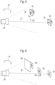
- a rear measuring device 8 comprises a camera 29, which is directed at all measuring devices 8 in front of it.
- a measuring mark 30 is arranged, wherein a Reference mark 30 is defined.
- a virtual optical chord 31 stretches between the reference mark 30 and the camera 29, which serves as a reference base for the position of the remaining measuring marks 30.
- All marks 30 of the measuring system 9 lie within a recording area 32 of the camera 29.
- the respective measuring or reference mark 30 comprises, for example, a crosshair on a reflective surface.
- the evaluation device 11 of the track position measuring system 9 the images from the camera 29 are continuously evaluated.
- the distances between the measuring devices 8 and the image scale of the camera 29 are known.
- the evaluation device 11 calculates an actual change in position of the measuring mark 30 with respect to the optical chord 31 from a displacement of a measuring mark 30 imaged on an image sensor.
- a displacement of a measuring mark 30 imaged on an image sensor In a given coordinate system x, y, z, corresponding displacement values ⁇ x, ⁇ y ( Fig. 4 ).
- These calculated displacement values ⁇ x, ⁇ y correspond to arrow height values measured with a conventional chord measuring system.
- camera 29 is configured to capture monochrome images to optimize analysis.
- the image sensor's resolution is 5 megapixels, for example. This allows displacements of the measurement marks 30 to be detected in millimeters.
- a recording frequency of approximately 200 Hz ensures that changes in position are detected immediately. This results in approximately 200 measurements per second.
- the camera 29 is coupled to a flashlight 33.
- a flashlight 33 For example, several high-performance LEDs are arranged around a lens of the camera 29 in order to flash in the direction of the measuring marks 30 synchronously with the triggering of the camera 29.
- the measuring marks 30 are designed as passive elements of the track position measuring system 9 ( Fig. 4 ).
- the respective measuring mark 30 is glued as a retroreflective foil to a suitable surface of the associated measuring device 8.
- Active measuring marks 30 are shown. These are controlled together with the camera 29 and illuminate in the direction of the camera 29.
- FIG. 6 A further improvement of the track position measuring system 9 used in the present invention is described in Fig. 6 shown. It is taken into account that, in exceptional cases, obstacles 34 may be located between the camera 29 and the measuring marks 30. For example, in the case of strong deflections in track curves, individual components may temporarily obscure the respective viewing axis. Several redundant measuring marks 30 are assigned to a measuring device 8 here, so that the position of the measuring device 8 can be reliably recorded even if one of the measuring marks 30 does not appear in the image taken by the camera 29.
- the factors used, k gf1 , k gf2 , k ga1 , k ga2 , k ga3 , k ga4 , k gv1 , k gv2 determine a control gain and are determined, for example, in tests or simulations. The same applies to the initial values of the operating parameters f 0 , a 0 , v 0 and to the initial values of the weighting factors g f1 (0), g f2 (0), g a1 (0), g a2 (0), g a3 (0), g a4 (0), g v1 (0), g v2 (0).
- empirical values are gained so that suitable values are available at the start of a work operation.
Landscapes
- Engineering & Computer Science (AREA)
- Architecture (AREA)
- Civil Engineering (AREA)
- Structural Engineering (AREA)
- Machines For Laying And Maintaining Railways (AREA)
Applications Claiming Priority (2)
| Application Number | Priority Date | Filing Date | Title |
|---|---|---|---|
| AT505022021 | 2021-06-21 | ||
| PCT/EP2022/066110 WO2022268566A1 (de) | 2021-06-21 | 2022-06-14 | Verfahren und system zur korrektur von vertikalen lagefehlern eines gleises |
Publications (3)
| Publication Number | Publication Date |
|---|---|
| EP4359609A1 EP4359609A1 (de) | 2024-05-01 |
| EP4359609C0 EP4359609C0 (de) | 2025-03-12 |
| EP4359609B1 true EP4359609B1 (de) | 2025-03-12 |
Family
ID=82163276
Family Applications (1)
| Application Number | Title | Priority Date | Filing Date |
|---|---|---|---|
| EP22733082.6A Active EP4359609B1 (de) | 2021-06-21 | 2022-06-14 | Verfahren und system zur korrektur von vertikalen lagefehlern eines gleises |
Country Status (7)
| Country | Link |
|---|---|
| US (1) | US20240271371A1 (pl) |
| EP (1) | EP4359609B1 (pl) |
| JP (1) | JP2024525380A (pl) |
| AT (1) | AT17790U1 (pl) |
| ES (1) | ES3029957T3 (pl) |
| PL (1) | PL4359609T3 (pl) |
| WO (1) | WO2022268566A1 (pl) |
Citations (11)
| Publication number | Priority date | Publication date | Assignee | Title |
|---|---|---|---|---|
| AT372437B (de) | 1981-01-16 | 1983-10-10 | Plasser Bahnbaumasch Franz | Verfahren zum verdichten der schotterbettung eines zu korrigierenden gleises |
| DE4102870A1 (de) | 1990-02-06 | 1991-08-08 | Plasser Bahnbaumasch Franz | Kontinuierlich verfahrbare gleisbaumaschine zum verdichten der schotterbettung eines gleises |
| EP0952254A1 (de) | 1998-03-27 | 1999-10-27 | Franz Plasser Bahnbaumaschinen-Industriegesellschaft m.b.H. | Verfahren zur Gleislagekorrektur |
| WO2006056215A1 (de) | 2004-11-22 | 2006-06-01 | Franz Plasser Bahnbaumaschinen- Industriegesellschaft Mbh | Verfahren zur korrektur von höhenlagefehlern eines gleises |
| WO2008009314A1 (de) | 2006-07-20 | 2008-01-24 | Franz Plasser Bahnbaumaschinen-Industriegesellschaft Mbh | Verfahren und maschine zum stabilisieren eines gleises |
| EP2902546A1 (de) | 2014-01-30 | 2015-08-05 | System7-Railsupport GmbH | Vorrichtung zum Verdichten der Schotterbettung eines Gleises |
| EP2960371A1 (de) | 2014-06-27 | 2015-12-30 | System7-Railsupport GmbH | Vorrichtung zum Vermessen von Gleisen |
| WO2016061602A1 (de) | 2014-10-22 | 2016-04-28 | System 7 - Railsupport GmbH | Verfahren zur messung und darstellung der gleisgeometrie einer gleisanlage |
| WO2018082798A1 (de) | 2016-11-04 | 2018-05-11 | Plasser & Theurer Export Von Bahnbaumaschinen Gesellschaft M.B.H. | Verfahren und gleisbaumaschine zur korrektur von gleislagefehlern |
| WO2019158288A1 (de) | 2018-02-13 | 2019-08-22 | Plasser & Theurer Export Von Bahnbaumaschinen Gmbh | Maschine zum stabilisieren eines gleises |
| WO2020177967A1 (de) | 2019-03-06 | 2020-09-10 | Plasser & Theurer Export Von Bahnbaumaschinen Gesellschaft M.B.H. | Gleisbaumaschine und verfahren zum stabilisieren eines schotterbettes |
Family Cites Families (1)
| Publication number | Priority date | Publication date | Assignee | Title |
|---|---|---|---|---|
| AT520795B1 (de) * | 2017-12-21 | 2020-03-15 | Plasser & Theurer Export Von Bahnbaumaschinen Gmbh | Gleisbaumaschine und Verfahren zum Nivellieren eines Gleises |
-
2021
- 2021-06-21 AT ATGM8021/2022U patent/AT17790U1/de unknown
-
2022
- 2022-06-14 JP JP2023578870A patent/JP2024525380A/ja active Pending
- 2022-06-14 ES ES22733082T patent/ES3029957T3/es active Active
- 2022-06-14 EP EP22733082.6A patent/EP4359609B1/de active Active
- 2022-06-14 PL PL22733082.6T patent/PL4359609T3/pl unknown
- 2022-06-14 WO PCT/EP2022/066110 patent/WO2022268566A1/de not_active Ceased
- 2022-06-14 US US18/566,744 patent/US20240271371A1/en active Pending
Patent Citations (12)
| Publication number | Priority date | Publication date | Assignee | Title |
|---|---|---|---|---|
| AT372437B (de) | 1981-01-16 | 1983-10-10 | Plasser Bahnbaumasch Franz | Verfahren zum verdichten der schotterbettung eines zu korrigierenden gleises |
| DE4102870A1 (de) | 1990-02-06 | 1991-08-08 | Plasser Bahnbaumasch Franz | Kontinuierlich verfahrbare gleisbaumaschine zum verdichten der schotterbettung eines gleises |
| EP0952254A1 (de) | 1998-03-27 | 1999-10-27 | Franz Plasser Bahnbaumaschinen-Industriegesellschaft m.b.H. | Verfahren zur Gleislagekorrektur |
| WO2006056215A1 (de) | 2004-11-22 | 2006-06-01 | Franz Plasser Bahnbaumaschinen- Industriegesellschaft Mbh | Verfahren zur korrektur von höhenlagefehlern eines gleises |
| WO2008009314A1 (de) | 2006-07-20 | 2008-01-24 | Franz Plasser Bahnbaumaschinen-Industriegesellschaft Mbh | Verfahren und maschine zum stabilisieren eines gleises |
| EP2902546A1 (de) | 2014-01-30 | 2015-08-05 | System7-Railsupport GmbH | Vorrichtung zum Verdichten der Schotterbettung eines Gleises |
| EP2960371A1 (de) | 2014-06-27 | 2015-12-30 | System7-Railsupport GmbH | Vorrichtung zum Vermessen von Gleisen |
| WO2016061602A1 (de) | 2014-10-22 | 2016-04-28 | System 7 - Railsupport GmbH | Verfahren zur messung und darstellung der gleisgeometrie einer gleisanlage |
| WO2018082798A1 (de) | 2016-11-04 | 2018-05-11 | Plasser & Theurer Export Von Bahnbaumaschinen Gesellschaft M.B.H. | Verfahren und gleisbaumaschine zur korrektur von gleislagefehlern |
| AT519317A1 (de) | 2016-11-04 | 2018-05-15 | Plasser & Theurer Exp Von Bahnbaumaschinen G M B H | Verfahren und Gleisbaumaschine zur Korrektur von Gleislagefehlern |
| WO2019158288A1 (de) | 2018-02-13 | 2019-08-22 | Plasser & Theurer Export Von Bahnbaumaschinen Gmbh | Maschine zum stabilisieren eines gleises |
| WO2020177967A1 (de) | 2019-03-06 | 2020-09-10 | Plasser & Theurer Export Von Bahnbaumaschinen Gesellschaft M.B.H. | Gleisbaumaschine und verfahren zum stabilisieren eines schotterbettes |
Non-Patent Citations (2)
| Title |
|---|
| "Handbuch Gleis : Unterbau, Oberbau, Instandhaltung, Wirtschaftlichkeit", 1 January 2010, EURAIL PRESS, ISBN: 978-3-7771-0400-3, article BERNHARD LICHTBERGER: "15.6 Gleisgeometrieberichtigung", pages: 416 - 503, XP009564314 |
| ANONYMOUS: "Trägheitsnavigationssystem", WIKIPEDIA, 23 February 2025 (2025-02-23), pages 1 - 6, XP093345356, Retrieved from the Internet <URL:https://de.wikipedia.org/w/index.php?title=Trägheitsnavigationssystem&oldid=253600627> |
Also Published As
| Publication number | Publication date |
|---|---|
| WO2022268566A1 (de) | 2022-12-29 |
| ES3029957T3 (en) | 2025-06-26 |
| JP2024525380A (ja) | 2024-07-12 |
| EP4359609A1 (de) | 2024-05-01 |
| AT17790U1 (de) | 2023-02-15 |
| US20240271371A1 (en) | 2024-08-15 |
| EP4359609C0 (de) | 2025-03-12 |
| PL4359609T3 (pl) | 2025-07-21 |
Similar Documents
| Publication | Publication Date | Title |
|---|---|---|
| EP4214103B1 (de) | Verfahren und system zur ermittlung eines soll-gleisverlaufs für eine lagekorrektur | |
| EP3481999B1 (de) | System und verfahren zum vermessen eines gleises | |
| DE102015205369B4 (de) | Verfahren zum Betrieb eines Federungssystems | |
| AT402519B (de) | Kontinuierlich verfahrbare gleisbaumaschine zum verdichten der schotterbettung eines gleises | |
| AT518579B1 (de) | Verfahren und Messsystem zum Erfassen eines Festpunktes neben einem Gleis | |
| DE3614981C2 (pl) | ||
| AT516278B1 (de) | Verfahren zur Messung und Darstellung der Gleisgeometrie einer Gleisanlage | |
| EP1339920B1 (de) | Laser-höhenregeleinrichtung für eine baumaschine | |
| EP3647494B1 (de) | Strassenfräsmaschine und verfahren zum steuern einer strassenfräsmaschine | |
| DE2416947B2 (de) | Verfahren zum begrenzen der verstellbewegung eines an einem allseitig schwenkbaren tragarm einer vortriebsmaschine gelagerten loesewerkzeuges auf den aufzufahrenden streckenquerschnitt und einrichtung zur ausuebung dieses verfahrens | |
| DE3409851A1 (de) | Einrichtung zur hoehenlage- und querneigungs-korrektur eines gleises | |
| EP4365058A2 (de) | Verfahren zum steuern einer gleisbaumaschine | |
| EP4249680A1 (de) | Selbstfahrende bodenfräsmaschine und verfahren zum steuern einer selbstfahrenden bodenfräsmaschine | |
| DE3007949C2 (de) | Fahrbare Maschine zum Überwachen und gegebenenfalls Korrigieren der Höhenlage und Querneigung eines Gleises | |
| EP4359609B1 (de) | Verfahren und system zur korrektur von vertikalen lagefehlern eines gleises | |
| EP3428342B1 (de) | Verfahren zur konstanthaltung einer von einer strassenmarkiermaschine aufzubringenden markierungslinie und strassenmarkiermaschine | |
| DE2109691A1 (de) | Vorrichtung zum Profilieren einer Oberflache | |
| EP4251491B1 (de) | Verfahren und system zur ermittlung von korrekturwerten für eine lagekorrektur eines gleises | |
| WO2025132499A1 (de) | System und verfahren zum instandhalten eines in einem schotterbett gelagerten gleises | |
| CH623624A5 (pl) | ||
| EP0722013B1 (de) | Verfahren und Gleisbaumaschine zur Durchführung von Gleisbauarbeiten | |
| AT524005A1 (de) | Verfahren und Maschine mit einem Stopfaggregat | |
| DE102012017337B4 (de) | Baumaschine mit einer Geschwindigkeitsmesseinrichtung, Verfahren zur Bestimmung der Fortbewegungsgeschwindigkeit einer Baumaschine und Verfahren zur Bestimmung des Bodenbearbeitungsvolumens einer Baumaschine | |
| AT527931B1 (de) | Verfahren, Messvorrichtung und System zum Bestimmen der Anordnung eines Gleisbauteils | |
| AT525140B1 (de) | Anordnung und Verfahren zum optischen Erfassen eines Gleises |
Legal Events
| Date | Code | Title | Description |
|---|---|---|---|
| STAA | Information on the status of an ep patent application or granted ep patent |
Free format text: STATUS: UNKNOWN |
|
| STAA | Information on the status of an ep patent application or granted ep patent |
Free format text: STATUS: THE INTERNATIONAL PUBLICATION HAS BEEN MADE |
|
| PUAI | Public reference made under article 153(3) epc to a published international application that has entered the european phase |
Free format text: ORIGINAL CODE: 0009012 |
|
| STAA | Information on the status of an ep patent application or granted ep patent |
Free format text: STATUS: REQUEST FOR EXAMINATION WAS MADE |
|
| 17P | Request for examination filed |
Effective date: 20240122 |
|
| AK | Designated contracting states |
Kind code of ref document: A1 Designated state(s): AL AT BE BG CH CY CZ DE DK EE ES FI FR GB GR HR HU IE IS IT LI LT LU LV MC MK MT NL NO PL PT RO RS SE SI SK SM TR |
|
| DAV | Request for validation of the european patent (deleted) | ||
| DAX | Request for extension of the european patent (deleted) | ||
| GRAP | Despatch of communication of intention to grant a patent |
Free format text: ORIGINAL CODE: EPIDOSNIGR1 |
|
| STAA | Information on the status of an ep patent application or granted ep patent |
Free format text: STATUS: GRANT OF PATENT IS INTENDED |
|
| INTG | Intention to grant announced |
Effective date: 20241030 |
|
| GRAS | Grant fee paid |
Free format text: ORIGINAL CODE: EPIDOSNIGR3 |
|
| GRAA | (expected) grant |
Free format text: ORIGINAL CODE: 0009210 |
|
| STAA | Information on the status of an ep patent application or granted ep patent |
Free format text: STATUS: THE PATENT HAS BEEN GRANTED |
|
| AK | Designated contracting states |
Kind code of ref document: B1 Designated state(s): AL AT BE BG CH CY CZ DE DK EE ES FI FR GB GR HR HU IE IS IT LI LT LU LV MC MK MT NL NO PL PT RO RS SE SI SK SM TR |
|
| REG | Reference to a national code |
Ref country code: GB Ref legal event code: FG4D Free format text: NOT ENGLISH |
|
| REG | Reference to a national code |
Ref country code: CH Ref legal event code: EP |
|
| REG | Reference to a national code |
Ref country code: DE Ref legal event code: R096 Ref document number: 502022003199 Country of ref document: DE |
|
| REG | Reference to a national code |
Ref country code: IE Ref legal event code: FG4D Free format text: LANGUAGE OF EP DOCUMENT: GERMAN |
|
| U01 | Request for unitary effect filed |
Effective date: 20250327 |
|
| U07 | Unitary effect registered |
Designated state(s): AT BE BG DE DK EE FI FR IT LT LU LV MT NL PT RO SE SI Effective date: 20250402 |
|
| REG | Reference to a national code |
Ref country code: ES Ref legal event code: FG2A Ref document number: 3029957 Country of ref document: ES Kind code of ref document: T3 Effective date: 20250626 |
|
| PG25 | Lapsed in a contracting state [announced via postgrant information from national office to epo] |
Ref country code: RS Free format text: LAPSE BECAUSE OF FAILURE TO SUBMIT A TRANSLATION OF THE DESCRIPTION OR TO PAY THE FEE WITHIN THE PRESCRIBED TIME-LIMIT Effective date: 20250612 |
|
| PG25 | Lapsed in a contracting state [announced via postgrant information from national office to epo] |
Ref country code: NO Free format text: LAPSE BECAUSE OF FAILURE TO SUBMIT A TRANSLATION OF THE DESCRIPTION OR TO PAY THE FEE WITHIN THE PRESCRIBED TIME-LIMIT Effective date: 20250612 |
|
| PG25 | Lapsed in a contracting state [announced via postgrant information from national office to epo] |
Ref country code: HR Free format text: LAPSE BECAUSE OF FAILURE TO SUBMIT A TRANSLATION OF THE DESCRIPTION OR TO PAY THE FEE WITHIN THE PRESCRIBED TIME-LIMIT Effective date: 20250312 |
|
| PG25 | Lapsed in a contracting state [announced via postgrant information from national office to epo] |
Ref country code: GR Free format text: LAPSE BECAUSE OF FAILURE TO SUBMIT A TRANSLATION OF THE DESCRIPTION OR TO PAY THE FEE WITHIN THE PRESCRIBED TIME-LIMIT Effective date: 20250613 |
|
| U20 | Renewal fee for the european patent with unitary effect paid |
Year of fee payment: 4 Effective date: 20250702 |
|
| PG25 | Lapsed in a contracting state [announced via postgrant information from national office to epo] |
Ref country code: SM Free format text: LAPSE BECAUSE OF FAILURE TO SUBMIT A TRANSLATION OF THE DESCRIPTION OR TO PAY THE FEE WITHIN THE PRESCRIBED TIME-LIMIT Effective date: 20250312 |
|
| PGFP | Annual fee paid to national office [announced via postgrant information from national office to epo] |
Ref country code: ES Payment date: 20250704 Year of fee payment: 4 |
|
| PGFP | Annual fee paid to national office [announced via postgrant information from national office to epo] |
Ref country code: PL Payment date: 20250529 Year of fee payment: 4 |
|
| PGFP | Annual fee paid to national office [announced via postgrant information from national office to epo] |
Ref country code: CH Payment date: 20250701 Year of fee payment: 4 |
|
| PG25 | Lapsed in a contracting state [announced via postgrant information from national office to epo] |
Ref country code: CZ Free format text: LAPSE BECAUSE OF FAILURE TO SUBMIT A TRANSLATION OF THE DESCRIPTION OR TO PAY THE FEE WITHIN THE PRESCRIBED TIME-LIMIT Effective date: 20250312 |
|
| PG25 | Lapsed in a contracting state [announced via postgrant information from national office to epo] |
Ref country code: SK Free format text: LAPSE BECAUSE OF FAILURE TO SUBMIT A TRANSLATION OF THE DESCRIPTION OR TO PAY THE FEE WITHIN THE PRESCRIBED TIME-LIMIT Effective date: 20250312 |
|
| PG25 | Lapsed in a contracting state [announced via postgrant information from national office to epo] |
Ref country code: IS Free format text: LAPSE BECAUSE OF FAILURE TO SUBMIT A TRANSLATION OF THE DESCRIPTION OR TO PAY THE FEE WITHIN THE PRESCRIBED TIME-LIMIT Effective date: 20250712 |