EP4359136B1 - A grinding roll and a grinding assembly comprising the grinding roll - Google Patents
A grinding roll and a grinding assembly comprising the grinding roll Download PDFInfo
- Publication number
- EP4359136B1 EP4359136B1 EP22744563.2A EP22744563A EP4359136B1 EP 4359136 B1 EP4359136 B1 EP 4359136B1 EP 22744563 A EP22744563 A EP 22744563A EP 4359136 B1 EP4359136 B1 EP 4359136B1
- Authority
- EP
- European Patent Office
- Prior art keywords
- flange
- wear protection
- grinding
- type
- protection liner
- Prior art date
- Legal status (The legal status is an assumption and is not a legal conclusion. Google has not performed a legal analysis and makes no representation as to the accuracy of the status listed.)
- Active
Links
Images


Classifications
-
- B—PERFORMING OPERATIONS; TRANSPORTING
- B02—CRUSHING, PULVERISING, OR DISINTEGRATING; PREPARATORY TREATMENT OF GRAIN FOR MILLING
- B02C—CRUSHING, PULVERISING, OR DISINTEGRATING IN GENERAL; MILLING GRAIN
- B02C4/00—Crushing or disintegrating by roller mills
- B02C4/28—Details
- B02C4/30—Shape or construction of rollers
-
- B—PERFORMING OPERATIONS; TRANSPORTING
- B02—CRUSHING, PULVERISING, OR DISINTEGRATING; PREPARATORY TREATMENT OF GRAIN FOR MILLING
- B02C—CRUSHING, PULVERISING, OR DISINTEGRATING IN GENERAL; MILLING GRAIN
- B02C4/00—Crushing or disintegrating by roller mills
- B02C4/02—Crushing or disintegrating by roller mills with two or more rollers
-
- B—PERFORMING OPERATIONS; TRANSPORTING
- B02—CRUSHING, PULVERISING, OR DISINTEGRATING; PREPARATORY TREATMENT OF GRAIN FOR MILLING
- B02C—CRUSHING, PULVERISING, OR DISINTEGRATING IN GENERAL; MILLING GRAIN
- B02C4/00—Crushing or disintegrating by roller mills
- B02C4/28—Details
- B02C4/30—Shape or construction of rollers
- B02C4/305—Wear resistant rollers
-
- B—PERFORMING OPERATIONS; TRANSPORTING
- B02—CRUSHING, PULVERISING, OR DISINTEGRATING; PREPARATORY TREATMENT OF GRAIN FOR MILLING
- B02C—CRUSHING, PULVERISING, OR DISINTEGRATING IN GENERAL; MILLING GRAIN
- B02C2210/00—Codes relating to different types of disintegrating devices
- B02C2210/01—Indication of wear on beaters, knives, rollers, anvils, linings and the like
-
- B—PERFORMING OPERATIONS; TRANSPORTING
- B02—CRUSHING, PULVERISING, OR DISINTEGRATING; PREPARATORY TREATMENT OF GRAIN FOR MILLING
- B02C—CRUSHING, PULVERISING, OR DISINTEGRATING IN GENERAL; MILLING GRAIN
- B02C2210/00—Codes relating to different types of disintegrating devices
- B02C2210/02—Features for generally used wear parts on beaters, knives, rollers, anvils, linings and the like
-
- B—PERFORMING OPERATIONS; TRANSPORTING
- B02—CRUSHING, PULVERISING, OR DISINTEGRATING; PREPARATORY TREATMENT OF GRAIN FOR MILLING
- B02C—CRUSHING, PULVERISING, OR DISINTEGRATING IN GENERAL; MILLING GRAIN
- B02C4/00—Crushing or disintegrating by roller mills
- B02C4/28—Details
- B02C4/283—Lateral sealing shields
-
- B—PERFORMING OPERATIONS; TRANSPORTING
- B30—PRESSES
- B30B—PRESSES IN GENERAL
- B30B3/00—Presses characterised by the use of rotary pressing members, e.g. rollers, rings, discs
- B30B3/005—Roll constructions
-
- B—PERFORMING OPERATIONS; TRANSPORTING
- B30—PRESSES
- B30B—PRESSES IN GENERAL
- B30B3/00—Presses characterised by the use of rotary pressing members, e.g. rollers, rings, discs
- B30B3/04—Presses characterised by the use of rotary pressing members, e.g. rollers, rings, discs co-operating with one another, e.g. with co-operating cones
Definitions
- the present invention relates to a grinding roll and a grinding assembly for comminution of materials comprising the grinding roll.
- the material to be comminuted or crushed is crushed not only by the crushing surface of the rolls, but also by particles in the material to be comminuted or crushed, hence the name interparticle crushing.
- a problem that may occur when feeding the material into the gap is to keep the material between the grinding roll(s) and to direct the material into the gap.
- Such flanges are exposed to a lot of wear from the material to be crushed, but the flanges are also exposed to pressure exerted by the material.
- flanges may be exposed to different amount of wear on different parts of the flange.
- such flanges may, in case of skewing, interfere with the edges of the opposite grinding roll and cause damage to both the flanges as well as the edges of the opposite grinding roll.
- An object of the invention is to provide for an increased life of the flange during operation of a grinding assembly.
- Another object of the invention is to provide for an improved flange design compared to conventional flanges known in the art.
- Another object of the invention is to provide for a more stable grinding roll during skewing events, wherein the grinding roll comprises at least one flange.
- a grinding roll comprising:
- the flange is fastened or mounted to, or in close proximity to, the at least one of the first and second end of the roll body in order to be kept in place.
- the flange is attached to the at least one of the first and second end of the roll body by means of a bolt and nut arrangement or screws.
- adhesives, welding, Velcro, magnets, or other, similar means may be used as well. In this way, it is possible to remove or replace the flange in an easy way.
- the flange may be attached to the roll body in one piece, wherein the flange is in one piece.
- the flange may be divided into a plurality of segments, wherein each segment may be attached to the roll body.
- the flange may be divided into the plurality of segments in order to facilitate manufacturing and mounting of the same.
- the plurality of segments may be attached to each other by stitch plates, sometimes also called fish plate or joint plates, or the like.
- second surface is here meant the surface of the flange facing exterior or outwardly of the roller body forming a continuing surface with the at least one of the first and second end of the roll body.
- the average covering area of the second type of wear protection liner elements is larger than that of the first type of wear protection liner element, it should be noted that a covering area of individual elements of the second type of wear protection liner elements may be smaller than a covering area of individual element of the first type of wear protection liner element and vice versa.
- the first type of wear protection liner elements should be fabricated with high strength "ductile" material to resist high load.
- the second type of wear protection liner elements uses a wear resistant material such that tungsten carbide or ceramics. With the present disclosure, a more durable flange and hence, the lifetime of the flange may be improved.
- the covering area of each of the second type of wear protection liner elements is larger than that of each of the first type of wear protection liner elements.
- An advantage with this embodiment is that efficient use of the first type of wear protection liner elements is provided.
- the lower part is not exposed to excessive abrasive wear based on the material movements. All material in the lower part of the flange may be exposed to crushing forces and the material is moving with the flange and hence, creates little or no abrasive wear on the flange.
- there is little or no abrasive wear on the flange in this radially lower part of the flange there is no need for a wear protection liner element with full covering of the flange.
- the tile plates are arranged in a close pattern facilitates provision of an improved protection against abrasive wear.
- the flange is protected against wear to a greater extend compared to e.g. when the first type of wear protection liner elements being arranged as a mosaic pattern as discussed above.
- the at least one radially upper part is exposed to a lot of wear from e.g. material movements. Therefore, by this arrangement, the lifetime of the flange may be further improved.
- the tile plates may be removed and replaced in an easy way when they are worn out.
- the tile plates are arranged on the at least one radially upper part adjacent the outer edge of the flange by using a nut and bolt arrangement or screws, but adhesive or other similar means may also be used.
- An advantage with this embodiment is that the impact on the flange during skewing events may be reduced.
- introducing the elastic shim between the second type of wear protection liner elements and the flange will reduce the impact on the flange and an edge on the opposite roller body during skewing events that may occur during operation of the grinding roll in a grinding assembly.
- a further advantage with this embodiment is that a stable grinding roll during operation, and especially during skewing events, may be achieved.
- the elastic shim is arranged between the second type of wear protection liner elements and the flange by using a nut and bolt arrangement or screws.
- other fastening or mounting arrangements may be possible as well.
- a flange ring segment arrangeable at a grinding roll along an edge thereof, the flange ring segment comprising a first surface and a second surface, the first surface forming a perpendicular continuing surface with a cylindrical outer surface of a grinding roll when arranged thereat, and the second surface forming a continuation of the an end of the grinding roll when arranged thereat; and the flange ring segment comprising wear protection liner elements on the first surface.
- the first surface comprising at least one radially lower part adjacent the cylindrical outer surface of the grinding roll when arranged thereat and at least one radially upper part adjacent an outer edge of the flange ring segment, wherein the at least one radially lower part comprises a first type of wear protection liner elements and the at least one radially upper part comprises a second type of wear protection liner elements, and wherein an average covering area of the second type of wear protection liner elements is larger than that of the first type of wear protection liner elements.
- the second type of wear protection liner elements comprises tile plates removably arranged in a close pattern along at least one radially upper part adjacent the outer edge of the flange ring segment.
- an elastic shim is arranged between the second type of wear protection liner elements and the flange ring segment.
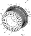
- the roll body 102 comprises a series of receiving bores that extends radially into the roll body 102 from the cylindrical outer surface 104. Each of the receiving bores receives a stud 126. Each of the studs 126 is formed from a material that is more durable than the roll body 102. The studs 126 may be replaced when worn to extend the life of the grinding roll 100. Preferably, the top end of the stud 126 extends past the cylindrical outer surface 104 such that material contacting the grinding roll 100 is first engaged by the top end of the stud 126. The crushed material forms a bed of material between the studs 126 to also enhance the durability of the cylindrical outer surface 104.
- the roll body 102 further comprises holes 132.
- the holes 132 may be configured to receive a bolt, screw, or the like in order to attach the flange 112 to the roll body 102.
- the holes 132 are pre-drilled holes in order to attach the flange 112 in an easy way.
- the roll body 102 may comprise an additional circle of holes configured to receive a bolt 142, screw or the like in order to attach the edge segments 140 or edge ring with edge wear protection bodies 128.
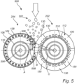
- a first straight line A has been drawn from the center of the first grinding roll 202 to the center of the second grinding roll 204.
- a second straight line B has been drawn from the center of the first grinding roll 202 to and through a first point on the first grinding roll 202, at which first point an active engagement between the second grinding roll 204 and the material to be crushed is started.
- the angle formed between the first straight line A and the second straight line B is defined as a nip angle ⁇ .
- a third straight line C has been drawn from the center of the first grinding roll 202 to and through a second point on the first grinding roll 204, at which second point an active crushing of the material between the first and second grinding rolls 202, 204 starts during operation of the grinding assembly 500.
- the outer edge 114 of the flange 112 attached to the first grinding roll 202 extends sufficient radially past the cylindrical outer surface 104 of the first grinding roll 202 to extend across the gap between the first and the second grinding rolls 202, 204 to a point on the second grinding roll 204, at which point the active engagement between the second grinding roll 204 and the material 502 to be crushed starts.
- a difference between the pre-compressed section 506 and the crushing section 508 is that the material 502 in the pre-compression section moves in relation to the flanges 112, while the material 502 in the crushing section 508 moves with the at least one flange 112. On the other hand, the material 502 in the crushing section 508 do exert a significant axial force on the flanges 112.
- Figure 3A-C illustrates one flange segment 130 for forming the flange 112 from different point of views.
- Fig. 3A further illustrates a front view of the flange segment 130.
- Fig. 3B-C illustrates a cross section of the flange segment 130.
- the flange segment 130 is in line with, and has the same features as, the flange 112 that has been discussed above in connection with Figs 1 , 2A-B and 5 .
- Fig. 3A-C also illustrates the first type of wear protection liner elements 122 and the second type of wear protection liner elements 124 in further detail.
- the elastic shim 306 may comprise a spring assembly 402 in order to facilitate the similar provision, namely, to reduce the impact on the flange 112 during skewing events.
- the spring assembly 402 is arranged between the second type of wear protection liner elements 124 and the flange 112. Although four springs are illustrated for the spring assembly 402 in Fig. 4A-B , it should be noted that any number of springs may be used for the spring assembly 402.
- the second type of wear protection liner elements 124 is slided into place and thereafter, the spring assembly 402 is installed from the second surface 208 of the flange segment 130 as illustrated.
- the at least one radially upper and lower parts of the first surface of the flange may be of any suitable size and shape depending on the material to be comminution and on the type of grinding assembly that is used.
- the arrangement of the elastic shim may also vary depending on the grinding assembly.
Landscapes
- Engineering & Computer Science (AREA)
- Food Science & Technology (AREA)
- Crushing And Grinding (AREA)
- Constituent Portions Of Griding Lathes, Driving, Sensing And Control (AREA)
- Polishing Bodies And Polishing Tools (AREA)
- Rolls And Other Rotary Bodies (AREA)
Priority Applications (1)
| Application Number | Priority Date | Filing Date | Title |
|---|---|---|---|
| RS20250647A RS66965B1 (sr) | 2021-06-23 | 2022-06-20 | Valjak za mlevenje i sklop za mlevenje koji sadrži valjak za mlevenje |
Applications Claiming Priority (2)
| Application Number | Priority Date | Filing Date | Title |
|---|---|---|---|
| US17/355,447 US11612895B2 (en) | 2021-06-23 | 2021-06-23 | Grinding roll and a grinding assembly comprising the grinding roll |
| PCT/US2022/034140 WO2022271579A1 (en) | 2021-06-23 | 2022-06-20 | A grinding roll and a grinding assembly comprising the grinding roll |
Publications (2)
| Publication Number | Publication Date |
|---|---|
| EP4359136A1 EP4359136A1 (en) | 2024-05-01 |
| EP4359136B1 true EP4359136B1 (en) | 2025-04-09 |
Family
ID=82655186
Family Applications (1)
| Application Number | Title | Priority Date | Filing Date |
|---|---|---|---|
| EP22744563.2A Active EP4359136B1 (en) | 2021-06-23 | 2022-06-20 | A grinding roll and a grinding assembly comprising the grinding roll |
Country Status (12)
| Country | Link |
|---|---|
| US (1) | US11612895B2 (pt) |
| EP (1) | EP4359136B1 (pt) |
| CN (2) | CN219051510U (pt) |
| AU (1) | AU2021221662A1 (pt) |
| CA (1) | CA3220632A1 (pt) |
| CL (1) | CL2023003577A1 (pt) |
| FI (1) | FI4359136T3 (pt) |
| MX (1) | MX2023015133A (pt) |
| PE (1) | PE20240273A1 (pt) |
| PT (1) | PT4359136T (pt) |
| RS (1) | RS66965B1 (pt) |
| WO (1) | WO2022271579A1 (pt) |
Families Citing this family (1)
| Publication number | Priority date | Publication date | Assignee | Title |
|---|---|---|---|---|
| US11612895B2 (en) * | 2021-06-23 | 2023-03-28 | Metso Outotec USA Inc. | Grinding roll and a grinding assembly comprising the grinding roll |
Family Cites Families (16)
| Publication number | Priority date | Publication date | Assignee | Title |
|---|---|---|---|---|
| DE4037816A1 (de) * | 1990-11-28 | 1992-06-04 | Kloeckner Humboldt Deutz Ag | Walzwerk |
| WO2007105039A2 (en) * | 2006-03-15 | 2007-09-20 | Berend Jan Werkman | Lining arrangement |
| DK176624B1 (da) * | 2007-07-25 | 2008-12-01 | Smidth As F L | Valsepresse med fleksible ringskivesektioner |
| CN103945945A (zh) * | 2011-12-21 | 2014-07-23 | Fl史密斯公司 | 辊子耐磨表面的插件布置 |
| DK2756886T3 (en) | 2012-04-20 | 2017-09-25 | Metso Minerals (Sweden) Ab | Roll crusher with at least one roller comprising a flange. |
| US8833687B2 (en) * | 2012-04-20 | 2014-09-16 | Metso Minerals Industries, Inc. | Crushing roll with edge protection |
| US8708264B2 (en) * | 2012-04-20 | 2014-04-29 | Metso Minerals (Sweden) Ab | Roller crusher having at least one roller comprising a flange |
| US9724697B2 (en) * | 2015-07-02 | 2017-08-08 | Dash Llc | Wear indication devices, and related assemblies and methods |
| CN206868316U (zh) * | 2017-06-12 | 2018-01-12 | 马鞍山格林环保科技股份有限公司 | 一种新型耐磨高压辊磨机 |
| CN208407127U (zh) * | 2018-02-22 | 2019-01-22 | 江阴兴澄特种钢铁有限公司 | 一种破碎机的压辊装置 |
| DE102018108690A1 (de) | 2018-04-12 | 2019-10-17 | Thyssenkrupp Ag | Mahlwalze und Walzenpresse |
| DE102019200190A1 (de) * | 2019-01-09 | 2020-07-09 | Thyssenkrupp Ag | Mahlwalze mit Randelementen |
| DE102019209514A1 (de) * | 2019-06-28 | 2020-12-31 | Thyssenkrupp Ag | Walzenmühle und Verfahren zum Betreiben einer Walzenmühle |
| DE102019209511A1 (de) * | 2019-06-28 | 2020-12-31 | Thyssenkrupp Ag | Walzenmühle mit Randelementen und Verfahren zum Einstellen eines stirnseitigen Spalts der Walzenmühle |
| CN112295659B (zh) | 2020-10-26 | 2022-04-29 | 辽宁五寰特种材料与智能装备产业技术研究院有限公司 | 一种高压辊磨机辊系结构 |
| US11612895B2 (en) * | 2021-06-23 | 2023-03-28 | Metso Outotec USA Inc. | Grinding roll and a grinding assembly comprising the grinding roll |
-
2021
- 2021-06-23 US US17/355,447 patent/US11612895B2/en active Active
- 2021-08-25 AU AU2021221662A patent/AU2021221662A1/en active Pending
-
2022
- 2022-06-16 CN CN202221530390.XU patent/CN219051510U/zh not_active Withdrawn - After Issue
- 2022-06-16 CN CN202210685677.8A patent/CN115501942B/zh active Active
- 2022-06-20 CA CA3220632A patent/CA3220632A1/en active Pending
- 2022-06-20 RS RS20250647A patent/RS66965B1/sr unknown
- 2022-06-20 WO PCT/US2022/034140 patent/WO2022271579A1/en not_active Ceased
- 2022-06-20 EP EP22744563.2A patent/EP4359136B1/en active Active
- 2022-06-20 PT PT227445632T patent/PT4359136T/pt unknown
- 2022-06-20 PE PE2023003279A patent/PE20240273A1/es unknown
- 2022-06-20 FI FIEP22744563.2T patent/FI4359136T3/fi active
- 2022-06-20 MX MX2023015133A patent/MX2023015133A/es unknown
-
2023
- 2023-11-30 CL CL2023003577A patent/CL2023003577A1/es unknown
Also Published As
| Publication number | Publication date |
|---|---|
| CL2023003577A1 (es) | 2024-07-12 |
| CN115501942A (zh) | 2022-12-23 |
| PT4359136T (pt) | 2025-07-02 |
| AU2021221662A1 (en) | 2023-01-19 |
| CN115501942B (zh) | 2024-10-08 |
| US20220410166A1 (en) | 2022-12-29 |
| CN219051510U (zh) | 2023-05-23 |
| RS66965B1 (sr) | 2025-07-31 |
| EP4359136A1 (en) | 2024-05-01 |
| US11612895B2 (en) | 2023-03-28 |
| WO2022271579A1 (en) | 2022-12-29 |
| MX2023015133A (es) | 2024-04-16 |
| PE20240273A1 (es) | 2024-02-19 |
| WO2022271579A9 (en) | 2023-03-02 |
| CA3220632A1 (en) | 2022-12-29 |
| FI4359136T3 (fi) | 2025-06-27 |
Similar Documents
| Publication | Publication Date | Title |
|---|---|---|
| CN100457276C (zh) | 用于压碎粒状物料的磨辊 | |
| AU2013202272B2 (en) | Crushing roll with edge protection | |
| AU2020201923B2 (en) | Crusher comprising replaceable protective liners | |
| US9718063B2 (en) | Press roll for a roll press | |
| US20150083839A1 (en) | Press roll | |
| EP4359136B1 (en) | A grinding roll and a grinding assembly comprising the grinding roll | |
| CN220071757U (zh) | 磨损保护部件和岩石破碎机 | |
| US20170021357A1 (en) | Roller and Replaceable Surface Segments for Roller | |
| US20240269682A1 (en) | Grinding roll | |
| EA048550B1 (ru) | Измельчающий валок и измельчающее устройство, содержащее измельчающий валок | |
| CN110681450B (zh) | 一种轮碾机碾轮及轮碾机 | |
| KR102392240B1 (ko) | 분리형 분쇄 롤러 조립체 |
Legal Events
| Date | Code | Title | Description |
|---|---|---|---|
| STAA | Information on the status of an ep patent application or granted ep patent |
Free format text: STATUS: UNKNOWN |
|
| STAA | Information on the status of an ep patent application or granted ep patent |
Free format text: STATUS: THE INTERNATIONAL PUBLICATION HAS BEEN MADE |
|
| PUAI | Public reference made under article 153(3) epc to a published international application that has entered the european phase |
Free format text: ORIGINAL CODE: 0009012 |
|
| STAA | Information on the status of an ep patent application or granted ep patent |
Free format text: STATUS: REQUEST FOR EXAMINATION WAS MADE |
|
| 17P | Request for examination filed |
Effective date: 20231128 |
|
| AK | Designated contracting states |
Kind code of ref document: A1 Designated state(s): AL AT BE BG CH CY CZ DE DK EE ES FI FR GB GR HR HU IE IS IT LI LT LU LV MC MK MT NL NO PL PT RO RS SE SI SK SM TR |
|
| DAV | Request for validation of the european patent (deleted) | ||
| DAX | Request for extension of the european patent (deleted) | ||
| GRAP | Despatch of communication of intention to grant a patent |
Free format text: ORIGINAL CODE: EPIDOSNIGR1 |
|
| STAA | Information on the status of an ep patent application or granted ep patent |
Free format text: STATUS: GRANT OF PATENT IS INTENDED |
|
| INTG | Intention to grant announced |
Effective date: 20241219 |
|
| GRAS | Grant fee paid |
Free format text: ORIGINAL CODE: EPIDOSNIGR3 |
|
| GRAA | (expected) grant |
Free format text: ORIGINAL CODE: 0009210 |
|
| STAA | Information on the status of an ep patent application or granted ep patent |
Free format text: STATUS: THE PATENT HAS BEEN GRANTED |
|
| AK | Designated contracting states |
Kind code of ref document: B1 Designated state(s): AL AT BE BG CH CY CZ DE DK EE ES FI FR GB GR HR HU IE IS IT LI LT LU LV MC MK MT NL NO PL PT RO RS SE SI SK SM TR |
|
| REG | Reference to a national code |
Ref country code: GB Ref legal event code: FG4D |
|
| REG | Reference to a national code |
Ref country code: CH Ref legal event code: EP |
|
| REG | Reference to a national code |
Ref country code: DE Ref legal event code: R096 Ref document number: 602022013005 Country of ref document: DE |
|
| REG | Reference to a national code |
Ref country code: IE Ref legal event code: FG4D |
|
| P01 | Opt-out of the competence of the unified patent court (upc) registered |
Free format text: CASE NUMBER: APP_16709/2025 Effective date: 20250407 |
|
| REG | Reference to a national code |
Ref country code: FI Ref legal event code: FGE |
|
| REG | Reference to a national code |
Ref country code: PT Ref legal event code: SC4A Ref document number: 4359136 Country of ref document: PT Date of ref document: 20250702 Kind code of ref document: T Free format text: AVAILABILITY OF NATIONAL TRANSLATION Effective date: 20250627 |
|
| PGFP | Annual fee paid to national office [announced via postgrant information from national office to epo] |
Ref country code: FI Payment date: 20250620 Year of fee payment: 4 |
|
| PGFP | Annual fee paid to national office [announced via postgrant information from national office to epo] |
Ref country code: DE Payment date: 20250604 Year of fee payment: 4 |
|
| PGFP | Annual fee paid to national office [announced via postgrant information from national office to epo] |
Ref country code: RS Payment date: 20250610 Year of fee payment: 4 |
|
| REG | Reference to a national code |
Ref country code: SE Ref legal event code: TRGR |
|
| PGFP | Annual fee paid to national office [announced via postgrant information from national office to epo] |
Ref country code: AT Payment date: 20250721 Year of fee payment: 4 |
|
| PGFP | Annual fee paid to national office [announced via postgrant information from national office to epo] |
Ref country code: TR Payment date: 20250626 Year of fee payment: 4 |
|
| PGFP | Annual fee paid to national office [announced via postgrant information from national office to epo] |
Ref country code: SE Payment date: 20250610 Year of fee payment: 4 |
|
| REG | Reference to a national code |
Ref country code: NL Ref legal event code: MP Effective date: 20250409 |
|
| PG25 | Lapsed in a contracting state [announced via postgrant information from national office to epo] |
Ref country code: NL Free format text: LAPSE BECAUSE OF FAILURE TO SUBMIT A TRANSLATION OF THE DESCRIPTION OR TO PAY THE FEE WITHIN THE PRESCRIBED TIME-LIMIT Effective date: 20250409 |
|
| REG | Reference to a national code |
Ref country code: AT Ref legal event code: MK05 Ref document number: 1783085 Country of ref document: AT Kind code of ref document: T Effective date: 20250409 |
|
| PG25 | Lapsed in a contracting state [announced via postgrant information from national office to epo] |
Ref country code: ES Free format text: LAPSE BECAUSE OF FAILURE TO SUBMIT A TRANSLATION OF THE DESCRIPTION OR TO PAY THE FEE WITHIN THE PRESCRIBED TIME-LIMIT Effective date: 20250409 |
|
| PGFP | Annual fee paid to national office [announced via postgrant information from national office to epo] |
Ref country code: PT Payment date: 20250725 Year of fee payment: 4 |
|
| REG | Reference to a national code |
Ref country code: LT Ref legal event code: MG9D |
|
| PG25 | Lapsed in a contracting state [announced via postgrant information from national office to epo] |
Ref country code: NO Free format text: LAPSE BECAUSE OF FAILURE TO SUBMIT A TRANSLATION OF THE DESCRIPTION OR TO PAY THE FEE WITHIN THE PRESCRIBED TIME-LIMIT Effective date: 20250709 Ref country code: GR Free format text: LAPSE BECAUSE OF FAILURE TO SUBMIT A TRANSLATION OF THE DESCRIPTION OR TO PAY THE FEE WITHIN THE PRESCRIBED TIME-LIMIT Effective date: 20250710 |
|
| PG25 | Lapsed in a contracting state [announced via postgrant information from national office to epo] |
Ref country code: PL Free format text: LAPSE BECAUSE OF FAILURE TO SUBMIT A TRANSLATION OF THE DESCRIPTION OR TO PAY THE FEE WITHIN THE PRESCRIBED TIME-LIMIT Effective date: 20250409 |
|
| PG25 | Lapsed in a contracting state [announced via postgrant information from national office to epo] |
Ref country code: BG Free format text: LAPSE BECAUSE OF FAILURE TO SUBMIT A TRANSLATION OF THE DESCRIPTION OR TO PAY THE FEE WITHIN THE PRESCRIBED TIME-LIMIT Effective date: 20250409 |
|
| PG25 | Lapsed in a contracting state [announced via postgrant information from national office to epo] |
Ref country code: HR Free format text: LAPSE BECAUSE OF FAILURE TO SUBMIT A TRANSLATION OF THE DESCRIPTION OR TO PAY THE FEE WITHIN THE PRESCRIBED TIME-LIMIT Effective date: 20250409 Ref country code: AT Free format text: LAPSE BECAUSE OF FAILURE TO SUBMIT A TRANSLATION OF THE DESCRIPTION OR TO PAY THE FEE WITHIN THE PRESCRIBED TIME-LIMIT Effective date: 20250409 |
|
| PGFP | Annual fee paid to national office [announced via postgrant information from national office to epo] |
Ref country code: RO Payment date: 20250619 Year of fee payment: 4 |
|
| PG25 | Lapsed in a contracting state [announced via postgrant information from national office to epo] |
Ref country code: IS Free format text: LAPSE BECAUSE OF FAILURE TO SUBMIT A TRANSLATION OF THE DESCRIPTION OR TO PAY THE FEE WITHIN THE PRESCRIBED TIME-LIMIT Effective date: 20250809 |
|
| PG25 | Lapsed in a contracting state [announced via postgrant information from national office to epo] |
Ref country code: LV Free format text: LAPSE BECAUSE OF FAILURE TO SUBMIT A TRANSLATION OF THE DESCRIPTION OR TO PAY THE FEE WITHIN THE PRESCRIBED TIME-LIMIT Effective date: 20250409 |
|
| PG25 | Lapsed in a contracting state [announced via postgrant information from national office to epo] |
Ref country code: DK Free format text: LAPSE BECAUSE OF FAILURE TO SUBMIT A TRANSLATION OF THE DESCRIPTION OR TO PAY THE FEE WITHIN THE PRESCRIBED TIME-LIMIT Effective date: 20250409 Ref country code: SM Free format text: LAPSE BECAUSE OF FAILURE TO SUBMIT A TRANSLATION OF THE DESCRIPTION OR TO PAY THE FEE WITHIN THE PRESCRIBED TIME-LIMIT Effective date: 20250409 |
|
| PG25 | Lapsed in a contracting state [announced via postgrant information from national office to epo] |
Ref country code: CZ Free format text: LAPSE BECAUSE OF FAILURE TO SUBMIT A TRANSLATION OF THE DESCRIPTION OR TO PAY THE FEE WITHIN THE PRESCRIBED TIME-LIMIT Effective date: 20250409 |
|
| PG25 | Lapsed in a contracting state [announced via postgrant information from national office to epo] |
Ref country code: EE Free format text: LAPSE BECAUSE OF FAILURE TO SUBMIT A TRANSLATION OF THE DESCRIPTION OR TO PAY THE FEE WITHIN THE PRESCRIBED TIME-LIMIT Effective date: 20250409 |
|
| PG25 | Lapsed in a contracting state [announced via postgrant information from national office to epo] |
Ref country code: SK Free format text: LAPSE BECAUSE OF FAILURE TO SUBMIT A TRANSLATION OF THE DESCRIPTION OR TO PAY THE FEE WITHIN THE PRESCRIBED TIME-LIMIT Effective date: 20250409 |
|
| REG | Reference to a national code |
Ref country code: CH Ref legal event code: H13 Free format text: ST27 STATUS EVENT CODE: U-0-0-H10-H13 (AS PROVIDED BY THE NATIONAL OFFICE) Effective date: 20260127 |
|
| PG25 | Lapsed in a contracting state [announced via postgrant information from national office to epo] |
Ref country code: IT Free format text: LAPSE BECAUSE OF FAILURE TO SUBMIT A TRANSLATION OF THE DESCRIPTION OR TO PAY THE FEE WITHIN THE PRESCRIBED TIME-LIMIT Effective date: 20250409 |
|
| PG25 | Lapsed in a contracting state [announced via postgrant information from national office to epo] |
Ref country code: MC Free format text: LAPSE BECAUSE OF FAILURE TO SUBMIT A TRANSLATION OF THE DESCRIPTION OR TO PAY THE FEE WITHIN THE PRESCRIBED TIME-LIMIT Effective date: 20250409 |
|
| PLBE | No opposition filed within time limit |
Free format text: ORIGINAL CODE: 0009261 |
|
| STAA | Information on the status of an ep patent application or granted ep patent |
Free format text: STATUS: NO OPPOSITION FILED WITHIN TIME LIMIT |