EP4357680B1 - An oven with steam cooking function - Google Patents
An oven with steam cooking function Download PDFInfo
- Publication number
- EP4357680B1 EP4357680B1 EP23200516.5A EP23200516A EP4357680B1 EP 4357680 B1 EP4357680 B1 EP 4357680B1 EP 23200516 A EP23200516 A EP 23200516A EP 4357680 B1 EP4357680 B1 EP 4357680B1
- Authority
- EP
- European Patent Office
- Prior art keywords
- oven
- valve
- shape memory
- enclosure
- spring
- Prior art date
- Legal status (The legal status is an assumption and is not a legal conclusion. Google has not performed a legal analysis and makes no representation as to the accuracy of the status listed.)
- Active
Links
Images

Classifications
-
- F—MECHANICAL ENGINEERING; LIGHTING; HEATING; WEAPONS; BLASTING
- F24—HEATING; RANGES; VENTILATING
- F24C—DOMESTIC STOVES OR RANGES ; DETAILS OF DOMESTIC STOVES OR RANGES, OF GENERAL APPLICATION
- F24C15/00—Details
- F24C15/32—Arrangements of ducts for hot gases, e.g. in or around baking ovens
- F24C15/322—Arrangements of ducts for hot gases, e.g. in or around baking ovens with forced circulation
- F24C15/327—Arrangements of ducts for hot gases, e.g. in or around baking ovens with forced circulation with air moisturising
-
- F—MECHANICAL ENGINEERING; LIGHTING; HEATING; WEAPONS; BLASTING
- F16—ENGINEERING ELEMENTS AND UNITS; GENERAL MEASURES FOR PRODUCING AND MAINTAINING EFFECTIVE FUNCTIONING OF MACHINES OR INSTALLATIONS; THERMAL INSULATION IN GENERAL
- F16K—VALVES; TAPS; COCKS; ACTUATING-FLOATS; DEVICES FOR VENTING OR AERATING
- F16K31/00—Actuating devices; Operating means; Releasing devices
- F16K31/002—Actuating devices; Operating means; Releasing devices actuated by temperature variation
Definitions
- the present invention relates to an oven wherein the steam cooking process is automatically performed.
- the user In order to perform steam cooking in ovens where steam cooking can be performed, the user must check the oven preheating time in the user manual. When the oven preheating time is reached, the user fills the water tank with the required amount and places the same in position. In this embodiment, the user is required to control and perform parameters such as the cooking time, the amount of water to be put into the tank by constantly checking the user manual.
- Another technical problem is that in the designs of existing shape memory alloy valves, sediment, lime, dirt and similar matters in the valve impair the stroke function of the valve and cause a reduction in the economic life thereof.
- Another technical problem is that the valves malfunction due to the irregular movement of the shape memory spring.
- JP 2004 242998 A discloses a rice cooker in which the supply of steam to the cooking pan is controlled by a valve.
- US 2014/013963 A1 discloses a steam cooking appliance with an overflow opening that branches into an overflow drain and a steam exhaust tube, wherein a steam valve is provided on the steam exhaust tube and configured to change, at least temporarily, a cross section of the steam exhaust tube.
- the aim of the present invention is the realization of a valve which enables the water supply system to be established automatically without user intervention.
- Another aim of the present invention is the realization of a valve which reduces energy consumption in the oven.
- Another aim of the present invention is the realization of a valve which eliminates the security risk in an environment which can be very hot and difficult to reach where the system is used by the user.
- Another aim of the present invention is the realization of a valve which is advantageous in terms of cost compared to electronic valves, and in terms of economic life and reliability compared to other mechanical valves comprising shape memory springs.
- the oven realized in order to attain the aim of the present invention, explicated in the first claim and the respective claims thereof, comprises a body, a casing surrounding the body; a water tank disposed between the casing and the body and filled with water; a pipe with one end opening into the water tank and the other end opening into the body and providing the transfer of water vapor into the body; a valve disposed on the pipe and providing the delivery of the water vapor into the body in a controlled manner; and a shape memory spring enabling the valve to open/close according to the temperature in the body.
- the oven of the present invention further comprises a connection member which ensures the connection of the valve and the pipe; a enclosure in the form of a cone tapering downwards in which the shape memory spring is vertically positioned and which provides the fixing of the spring; a sealing body positioned between said connection member and enclosure; and a piston positioned vertically in the sealing body, configured to block the fluid passage in a first position and allow the fluid passage in a second position, and entering the shape memory spring so as to move along the displacement direction from the first position to the second position.
- the oven (1) comprises a body (2), a casing surrounding the body (2); a water tank (3) disposed between the casing and the body (2) and filled with water; a pipe (4) with one end opening into the water tank (3) and the other end opening into the body (2) and providing the transfer of water vapor into the body (2); a valve (5) disposed on the pipe (4) and providing the delivery of the water vapor into the body (2) in a controlled manner; and a shape memory spring (7) enabling the valve (5) to open/close according to the temperature in the body (2) ( Figure 1 ).
- the steam cooking process is automatically performed without requiring the intervention of the user. Since the user does not open the oven (1) door, both safe use and energy savings are provided.
- valve (5) comprising the shape memory spring (7) is positioned on the outer wall of the body (2).
- the oven (1) comprises a spacer (13) which is disposed on the outer wall of the body (2) and whereon the valve (5) is mounted.
- the body (2) heat is transferred to the shape memory spring (7) by conduction and the valve (5) is opened or closed at the right temperature and time.
- the spacer (13) is manufactured from sheet metal.
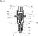
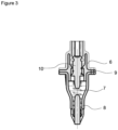
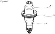
- the valve (5) comprises a connection member (6) which ensures the connection of the pipe (4); a shape memory spring (7) which enables the valve (5) to open/close automatically according to the temperature in the body (2); a enclosure (8) wherein the shape memory spring (7) is vertically positioned and which provides the fixing of the spring (7); a sealing body (9) which is positioned between said connection member (6) and enclosure (8); and a piston (10) which is positioned vertically in the sealing body (9), which is configured to block the fluid passage in a first position (14) and allow the fluid passage in a second position (15), and which enters the shape memory spring (7) so as to move along the displacement direction from the first position (14) to the second position (15).
- the shape memory spring (7) positioned vertically in the enclosure (8) gains potential force with the shear modulus thereof increasing approximately 5 times at this temperature so as to stretch and compress the piston (10).
- the shape memory spring (7) performs a vertical movement in the valve (5) and extends the economic life of the valve (5), and the shape memory spring (7) is referenced in the housing (8) such that the irregular movement thereof is kept under control.
- the vertical movement is performed in a proper manner and any valve (5) malfunction is prevented.
- any water accumulation therein is prevented so as to avoid dirt, sediment and similar formations.
- the heat in the body (2) is transferred to the shape memory spring (7) in the most effective and correct manner, and in the second position (15) where the valve (5) opens automatically when the desired temperature is reached the steam cooking process is performed and in the first position (14) where the valve (5) closes automatically when the desired temperature is reached, the steam cooking process is terminated.
- the heat in the body (2) is transferred to the shape memory spring (7) in the most efficient and correct manner so as to ensure that the valve (5) closes when the desired temperature is reached.
- the valve (5) provides the controlled transmission of water vapor into the body (2) through the pipe (4).
- the connection member (6) comprises a first connection end (6.1) where the valve (5) and the pipe (4) are connected, a channel (6.2) through which the water flows, and a second connection end (6.3) where the sealing body (9) is disposed.
- the sealing body (9) comprises a housing (9.1) wherein the piston (10) is positioned.
- at least one counter spring (11) is positioned between the housing (9.1) and the piston (10) so as to be pushed in the direction of the channel (6.2) and compressed. In the position where the counter spring (11) is compressed, at least one sealing gasket (12) is disposed in the piston (10).
- the piston (10) is in the form of a cone tapering downwards.
- the sealing body (9) maintains the vertical movement of the piston (10), thus allowing the same to move horizontally without oscillation.
- the conical structure of the piston (10) disposed in the housing (9.1) in the middle of the sealing body (9) and the sealing gasket (12) provide the sealing of the system when the valve (5) is in the first position (14).
- the water channels (6.2) provided in the connection member (6) ensure that the water flow is not blocked even if the piston (10) narrows the cross-section of the water flow.
- the enclosure (8) is in the form of a cone tapering downwards.
- the enclosure (8) comprises a first end (8.1) where the enclosure (8) joins with the sealing body (9); a second end (8.2) which tapers downwards from the sealing body (9); a gap (8.3) wherein the shape memory spring (7) is placed vertically; and a pin (8.5) having a conical pin end (8.4), which defines the path for the shape memory spring (7) while stretching and compressing with temperature change and prevents the same from getting stuck.
- the tapering structure of the pin end (8.4) ensures the stable movement of the shape memory spring (7).
- the tapering form of the second end (8.2) of the enclosure (8) provides the fixing of the shape memory spring (7).
- the opening between the gap (8.3) in the enclosure (8) and the point where the pin (8.5) joins the second end (8.2) of the enclosure (8) provides the control and position adjustment of the shape memory spring (7).
Landscapes
- Engineering & Computer Science (AREA)
- General Engineering & Computer Science (AREA)
- Mechanical Engineering (AREA)
- Chemical & Material Sciences (AREA)
- Combustion & Propulsion (AREA)
- Cookers (AREA)
Applications Claiming Priority (1)
| Application Number | Priority Date | Filing Date | Title |
|---|---|---|---|
| TR202215853 | 2022-10-18 |
Publications (2)
| Publication Number | Publication Date |
|---|---|
| EP4357680A1 EP4357680A1 (en) | 2024-04-24 |
| EP4357680B1 true EP4357680B1 (en) | 2025-04-30 |
Family
ID=88236661
Family Applications (1)
| Application Number | Title | Priority Date | Filing Date |
|---|---|---|---|
| EP23200516.5A Active EP4357680B1 (en) | 2022-10-18 | 2023-09-28 | An oven with steam cooking function |
Country Status (2)
| Country | Link |
|---|---|
| EP (1) | EP4357680B1 (pl) |
| PL (1) | PL4357680T3 (pl) |
Family Cites Families (3)
| Publication number | Priority date | Publication date | Assignee | Title |
|---|---|---|---|---|
| JP3757945B2 (ja) * | 2003-02-17 | 2006-03-22 | 松下電器産業株式会社 | 炊飯器 |
| US20140013963A1 (en) * | 2011-04-15 | 2014-01-16 | BSH Bosch und Siemens Hausgeräte GmbH | Steam cooking appliance, in particular a steam oven |
| DE102019103913A1 (de) * | 2019-02-15 | 2020-08-20 | Woco Industrietechnik Gmbh | Thermostatventil |
-
2023
- 2023-09-28 PL PL23200516.5T patent/PL4357680T3/pl unknown
- 2023-09-28 EP EP23200516.5A patent/EP4357680B1/en active Active
Also Published As
| Publication number | Publication date |
|---|---|
| PL4357680T3 (pl) | 2025-09-08 |
| EP4357680A1 (en) | 2024-04-24 |
Similar Documents
| Publication | Publication Date | Title |
|---|---|---|
| KR100929211B1 (ko) | 정유량 자동제어장치 | |
| CA2527433C (en) | Steam oven system having steam generator with controlled fill process | |
| EA020365B1 (ru) | Клапанное устройство газового прибора | |
| EP4357680B1 (en) | An oven with steam cooking function | |
| CN106015713B (zh) | 具有设定致动器的阀致动器 | |
| KR100914678B1 (ko) | 밸브 구동 장치 | |
| EP3088779B1 (en) | Soft throttling valve | |
| TR2022015853A2 (tr) | Buharli pi̇şi̇rme yapan bi̇r firin | |
| JP5121411B2 (ja) | 排水用温度調整バルブ | |
| US6957657B2 (en) | Safety valve, in particular for cooking plate gas and related mounting method | |
| KR20120023251A (ko) | 형상기억합금으로 구동되는 개폐밸브를 포함하는 온수 보일러 절수시스템 | |
| CN218761595U (zh) | 一种温控阀及热水器 | |
| CN117249274B (zh) | 一种温控阀、热水器及其运行方法 | |
| JP3947309B2 (ja) | 給湯システム、及びその制御方法 | |
| JP6431391B2 (ja) | ガスコンロ | |
| KR100871616B1 (ko) | 물 공급 장치 | |
| CN212429845U (zh) | 水路调节组件及具有其的供水系统 | |
| CN201053746Y (zh) | 贮水式热水器的水控装置 | |
| KR200347480Y1 (ko) | 보일러시스템의 3방향밸브 | |
| JP2011027297A (ja) | 熱水生成装置およびこれを用いた蒸気給湯システム | |
| KR102840565B1 (ko) | 난방수 순환용 차압 유량조절밸브 | |
| CN113865094B (zh) | 电热水器用进出水机构及电热水器 | |
| CN219300779U (zh) | 一种蒸汽保温挡板门 | |
| EP4276366B1 (en) | An oven with steam cooking function | |
| RU2647008C1 (ru) | Средство для промывания клапана |
Legal Events
| Date | Code | Title | Description |
|---|---|---|---|
| PUAI | Public reference made under article 153(3) epc to a published international application that has entered the european phase |
Free format text: ORIGINAL CODE: 0009012 |
|
| STAA | Information on the status of an ep patent application or granted ep patent |
Free format text: STATUS: REQUEST FOR EXAMINATION WAS MADE |
|
| 17P | Request for examination filed |
Effective date: 20230928 |
|
| AK | Designated contracting states |
Kind code of ref document: A1 Designated state(s): AL AT BE BG CH CY CZ DE DK EE ES FI FR GB GR HR HU IE IS IT LI LT LU LV MC ME MK MT NL NO PL PT RO RS SE SI SK SM TR |
|
| GRAP | Despatch of communication of intention to grant a patent |
Free format text: ORIGINAL CODE: EPIDOSNIGR1 |
|
| STAA | Information on the status of an ep patent application or granted ep patent |
Free format text: STATUS: GRANT OF PATENT IS INTENDED |
|
| INTG | Intention to grant announced |
Effective date: 20241223 |
|
| GRAS | Grant fee paid |
Free format text: ORIGINAL CODE: EPIDOSNIGR3 |
|
| GRAA | (expected) grant |
Free format text: ORIGINAL CODE: 0009210 |
|
| STAA | Information on the status of an ep patent application or granted ep patent |
Free format text: STATUS: THE PATENT HAS BEEN GRANTED |
|
| AK | Designated contracting states |
Kind code of ref document: B1 Designated state(s): AL AT BE BG CH CY CZ DE DK EE ES FI FR GB GR HR HU IE IS IT LI LT LU LV MC ME MK MT NL NO PL PT RO RS SE SI SK SM TR |
|
| REG | Reference to a national code |
Ref country code: CH Ref legal event code: EP Ref country code: GB Ref legal event code: FG4D |
|
| RIN1 | Information on inventor provided before grant (corrected) |
Inventor name: AYTAN, ONUR Inventor name: KAYA, OGUZHAN Inventor name: SERABATIR, DAVUT AYHAN Inventor name: KAYA, ALI ERALP Inventor name: BICER, EMRAH |
|
| REG | Reference to a national code |
Ref country code: IE Ref legal event code: FG4D |
|
| REG | Reference to a national code |
Ref country code: DE Ref legal event code: R096 Ref document number: 602023003185 Country of ref document: DE |
|
| REG | Reference to a national code |
Ref country code: NL Ref legal event code: MP Effective date: 20250430 |
|
| REG | Reference to a national code |
Ref country code: AT Ref legal event code: MK05 Ref document number: 1790321 Country of ref document: AT Kind code of ref document: T Effective date: 20250430 |
|
| PG25 | Lapsed in a contracting state [announced via postgrant information from national office to epo] |
Ref country code: FI Free format text: LAPSE BECAUSE OF FAILURE TO SUBMIT A TRANSLATION OF THE DESCRIPTION OR TO PAY THE FEE WITHIN THE PRESCRIBED TIME-LIMIT Effective date: 20250430 Ref country code: PT Free format text: LAPSE BECAUSE OF FAILURE TO SUBMIT A TRANSLATION OF THE DESCRIPTION OR TO PAY THE FEE WITHIN THE PRESCRIBED TIME-LIMIT Effective date: 20250901 Ref country code: ES Free format text: LAPSE BECAUSE OF FAILURE TO SUBMIT A TRANSLATION OF THE DESCRIPTION OR TO PAY THE FEE WITHIN THE PRESCRIBED TIME-LIMIT Effective date: 20250430 |
|
| PGFP | Annual fee paid to national office [announced via postgrant information from national office to epo] |
Ref country code: DE Payment date: 20250919 Year of fee payment: 3 |
|
| REG | Reference to a national code |
Ref country code: LT Ref legal event code: MG9D |
|
| PG25 | Lapsed in a contracting state [announced via postgrant information from national office to epo] |
Ref country code: GR Free format text: LAPSE BECAUSE OF FAILURE TO SUBMIT A TRANSLATION OF THE DESCRIPTION OR TO PAY THE FEE WITHIN THE PRESCRIBED TIME-LIMIT Effective date: 20250731 Ref country code: NO Free format text: LAPSE BECAUSE OF FAILURE TO SUBMIT A TRANSLATION OF THE DESCRIPTION OR TO PAY THE FEE WITHIN THE PRESCRIBED TIME-LIMIT Effective date: 20250730 |
|
| PG25 | Lapsed in a contracting state [announced via postgrant information from national office to epo] |
Ref country code: NL Free format text: LAPSE BECAUSE OF FAILURE TO SUBMIT A TRANSLATION OF THE DESCRIPTION OR TO PAY THE FEE WITHIN THE PRESCRIBED TIME-LIMIT Effective date: 20250430 |
|
| PGFP | Annual fee paid to national office [announced via postgrant information from national office to epo] |
Ref country code: TR Payment date: 20250919 Year of fee payment: 3 Ref country code: PL Payment date: 20250923 Year of fee payment: 3 |
|
| PG25 | Lapsed in a contracting state [announced via postgrant information from national office to epo] |
Ref country code: BG Free format text: LAPSE BECAUSE OF FAILURE TO SUBMIT A TRANSLATION OF THE DESCRIPTION OR TO PAY THE FEE WITHIN THE PRESCRIBED TIME-LIMIT Effective date: 20250430 |
|
| PG25 | Lapsed in a contracting state [announced via postgrant information from national office to epo] |
Ref country code: HR Free format text: LAPSE BECAUSE OF FAILURE TO SUBMIT A TRANSLATION OF THE DESCRIPTION OR TO PAY THE FEE WITHIN THE PRESCRIBED TIME-LIMIT Effective date: 20250430 |
|
| PG25 | Lapsed in a contracting state [announced via postgrant information from national office to epo] |
Ref country code: AT Free format text: LAPSE BECAUSE OF FAILURE TO SUBMIT A TRANSLATION OF THE DESCRIPTION OR TO PAY THE FEE WITHIN THE PRESCRIBED TIME-LIMIT Effective date: 20250430 |
|
| PG25 | Lapsed in a contracting state [announced via postgrant information from national office to epo] |
Ref country code: RS Free format text: LAPSE BECAUSE OF FAILURE TO SUBMIT A TRANSLATION OF THE DESCRIPTION OR TO PAY THE FEE WITHIN THE PRESCRIBED TIME-LIMIT Effective date: 20250731 |
|
| PG25 | Lapsed in a contracting state [announced via postgrant information from national office to epo] |
Ref country code: IS Free format text: LAPSE BECAUSE OF FAILURE TO SUBMIT A TRANSLATION OF THE DESCRIPTION OR TO PAY THE FEE WITHIN THE PRESCRIBED TIME-LIMIT Effective date: 20250830 |
|
| PG25 | Lapsed in a contracting state [announced via postgrant information from national office to epo] |
Ref country code: LV Free format text: LAPSE BECAUSE OF FAILURE TO SUBMIT A TRANSLATION OF THE DESCRIPTION OR TO PAY THE FEE WITHIN THE PRESCRIBED TIME-LIMIT Effective date: 20250430 |
|
| PG25 | Lapsed in a contracting state [announced via postgrant information from national office to epo] |
Ref country code: SM Free format text: LAPSE BECAUSE OF FAILURE TO SUBMIT A TRANSLATION OF THE DESCRIPTION OR TO PAY THE FEE WITHIN THE PRESCRIBED TIME-LIMIT Effective date: 20250430 Ref country code: DK Free format text: LAPSE BECAUSE OF FAILURE TO SUBMIT A TRANSLATION OF THE DESCRIPTION OR TO PAY THE FEE WITHIN THE PRESCRIBED TIME-LIMIT Effective date: 20250430 |
|
| PGFP | Annual fee paid to national office [announced via postgrant information from national office to epo] |
Ref country code: IT Payment date: 20250930 Year of fee payment: 3 |
|
| PG25 | Lapsed in a contracting state [announced via postgrant information from national office to epo] |
Ref country code: CZ Free format text: LAPSE BECAUSE OF FAILURE TO SUBMIT A TRANSLATION OF THE DESCRIPTION OR TO PAY THE FEE WITHIN THE PRESCRIBED TIME-LIMIT Effective date: 20250430 |
|
| PG25 | Lapsed in a contracting state [announced via postgrant information from national office to epo] |
Ref country code: EE Free format text: LAPSE BECAUSE OF FAILURE TO SUBMIT A TRANSLATION OF THE DESCRIPTION OR TO PAY THE FEE WITHIN THE PRESCRIBED TIME-LIMIT Effective date: 20250430 |
|
| PG25 | Lapsed in a contracting state [announced via postgrant information from national office to epo] |
Ref country code: SK Free format text: LAPSE BECAUSE OF FAILURE TO SUBMIT A TRANSLATION OF THE DESCRIPTION OR TO PAY THE FEE WITHIN THE PRESCRIBED TIME-LIMIT Effective date: 20250430 |
|
| REG | Reference to a national code |
Ref country code: DE Ref legal event code: R097 Ref document number: 602023003185 Country of ref document: DE |
|
| PG25 | Lapsed in a contracting state [announced via postgrant information from national office to epo] |
Ref country code: RO Free format text: LAPSE BECAUSE OF FAILURE TO SUBMIT A TRANSLATION OF THE DESCRIPTION OR TO PAY THE FEE WITHIN THE PRESCRIBED TIME-LIMIT Effective date: 20250430 |
|
| PLBE | No opposition filed within time limit |
Free format text: ORIGINAL CODE: 0009261 |
|
| STAA | Information on the status of an ep patent application or granted ep patent |
Free format text: STATUS: NO OPPOSITION FILED WITHIN TIME LIMIT |
|
| REG | Reference to a national code |
Ref country code: CH Ref legal event code: L10 Free format text: ST27 STATUS EVENT CODE: U-0-0-L10-L00 (AS PROVIDED BY THE NATIONAL OFFICE) Effective date: 20260311 |
|
| 26N | No opposition filed |
Effective date: 20260202 |