EP4353613A1 - Exterior part and combination packaging container equipped with same, method for producing same, and method for opening same - Google Patents
Exterior part and combination packaging container equipped with same, method for producing same, and method for opening same Download PDFInfo
- Publication number
- EP4353613A1 EP4353613A1 EP23202602.1A EP23202602A EP4353613A1 EP 4353613 A1 EP4353613 A1 EP 4353613A1 EP 23202602 A EP23202602 A EP 23202602A EP 4353613 A1 EP4353613 A1 EP 4353613A1
- Authority
- EP
- European Patent Office
- Prior art keywords
- container
- outer part
- face
- blank
- receiving area
- Prior art date
- Legal status (The legal status is an assumption and is not a legal conclusion. Google has not performed a legal analysis and makes no representation as to the accuracy of the status listed.)
- Pending
Links
- 238000004806 packaging method and process Methods 0.000 title claims abstract description 67
- 238000000034 method Methods 0.000 title claims abstract description 31
- 238000004519 manufacturing process Methods 0.000 title claims abstract description 9
- 238000000926 separation method Methods 0.000 claims description 42
- 239000000463 material Substances 0.000 claims description 30
- 230000008878 coupling Effects 0.000 claims description 11
- 238000010168 coupling process Methods 0.000 claims description 11
- 238000005859 coupling reaction Methods 0.000 claims description 11
- 238000005520 cutting process Methods 0.000 claims description 9
- 239000004033 plastic Substances 0.000 claims description 9
- 230000008901 benefit Effects 0.000 description 22
- 238000007789 sealing Methods 0.000 description 15
- 238000004064 recycling Methods 0.000 description 12
- 230000008569 process Effects 0.000 description 9
- 229920002678 cellulose Polymers 0.000 description 5
- 239000001913 cellulose Substances 0.000 description 5
- 239000010410 layer Substances 0.000 description 5
- 239000000123 paper Substances 0.000 description 3
- 238000004804 winding Methods 0.000 description 3
- 240000001439 Opuntia Species 0.000 description 2
- 235000004727 Opuntia ficus indica Nutrition 0.000 description 2
- 230000004308 accommodation Effects 0.000 description 2
- 239000000853 adhesive Substances 0.000 description 2
- 230000001070 adhesive effect Effects 0.000 description 2
- 239000012790 adhesive layer Substances 0.000 description 2
- 210000003323 beak Anatomy 0.000 description 2
- 239000011248 coating agent Substances 0.000 description 2
- 238000000576 coating method Methods 0.000 description 2
- 238000010276 construction Methods 0.000 description 2
- 238000006073 displacement reaction Methods 0.000 description 2
- 230000000694 effects Effects 0.000 description 2
- 238000007639 printing Methods 0.000 description 2
- 239000005871 repellent Substances 0.000 description 2
- 239000000243 solution Substances 0.000 description 2
- 230000000007 visual effect Effects 0.000 description 2
- 238000010521 absorption reaction Methods 0.000 description 1
- 230000009471 action Effects 0.000 description 1
- 238000004026 adhesive bonding Methods 0.000 description 1
- 230000005540 biological transmission Effects 0.000 description 1
- 239000013590 bulk material Substances 0.000 description 1
- 239000003795 chemical substances by application Substances 0.000 description 1
- 239000002131 composite material Substances 0.000 description 1
- 238000005034 decoration Methods 0.000 description 1
- 238000001514 detection method Methods 0.000 description 1
- 230000007613 environmental effect Effects 0.000 description 1
- 238000001746 injection moulding Methods 0.000 description 1
- 238000009413 insulation Methods 0.000 description 1
- 239000008267 milk Substances 0.000 description 1
- 210000004080 milk Anatomy 0.000 description 1
- 235000013336 milk Nutrition 0.000 description 1
- 230000003287 optical effect Effects 0.000 description 1
- 239000002985 plastic film Substances 0.000 description 1
- 239000002861 polymer material Substances 0.000 description 1
- 238000003825 pressing Methods 0.000 description 1
- 239000002994 raw material Substances 0.000 description 1
- 230000002787 reinforcement Effects 0.000 description 1
- 238000004904 shortening Methods 0.000 description 1
- 238000003892 spreading Methods 0.000 description 1
- 230000007480 spreading Effects 0.000 description 1
- 238000003860 storage Methods 0.000 description 1
- 230000008961 swelling Effects 0.000 description 1
Images


Classifications
-
- B—PERFORMING OPERATIONS; TRANSPORTING
- B65—CONVEYING; PACKING; STORING; HANDLING THIN OR FILAMENTARY MATERIAL
- B65D—CONTAINERS FOR STORAGE OR TRANSPORT OF ARTICLES OR MATERIALS, e.g. BAGS, BARRELS, BOTTLES, BOXES, CANS, CARTONS, CRATES, DRUMS, JARS, TANKS, HOPPERS, FORWARDING CONTAINERS; ACCESSORIES, CLOSURES, OR FITTINGS THEREFOR; PACKAGING ELEMENTS; PACKAGES
- B65D65/00—Wrappers or flexible covers; Packaging materials of special type or form
- B65D65/02—Wrappers or flexible covers
- B65D65/04—Wrappers or flexible covers non-rectangular
-
- B—PERFORMING OPERATIONS; TRANSPORTING
- B65—CONVEYING; PACKING; STORING; HANDLING THIN OR FILAMENTARY MATERIAL
- B65D—CONTAINERS FOR STORAGE OR TRANSPORT OF ARTICLES OR MATERIALS, e.g. BAGS, BARRELS, BOTTLES, BOXES, CANS, CARTONS, CRATES, DRUMS, JARS, TANKS, HOPPERS, FORWARDING CONTAINERS; ACCESSORIES, CLOSURES, OR FITTINGS THEREFOR; PACKAGING ELEMENTS; PACKAGES
- B65D25/00—Details of other kinds or types of rigid or semi-rigid containers
- B65D25/34—Coverings or external coatings
- B65D25/36—Coverings or external coatings formed by applying sheet material
-
- B—PERFORMING OPERATIONS; TRANSPORTING
- B65—CONVEYING; PACKING; STORING; HANDLING THIN OR FILAMENTARY MATERIAL
- B65B—MACHINES, APPARATUS OR DEVICES FOR, OR METHODS OF, PACKAGING ARTICLES OR MATERIALS; UNPACKING
- B65B11/00—Wrapping, e.g. partially or wholly enclosing, articles or quantities of material, in strips, sheets or blanks, of flexible material
-
- B—PERFORMING OPERATIONS; TRANSPORTING
- B65—CONVEYING; PACKING; STORING; HANDLING THIN OR FILAMENTARY MATERIAL
- B65B—MACHINES, APPARATUS OR DEVICES FOR, OR METHODS OF, PACKAGING ARTICLES OR MATERIALS; UNPACKING
- B65B69/00—Unpacking of articles or materials, not otherwise provided for
-
- B—PERFORMING OPERATIONS; TRANSPORTING
- B65—CONVEYING; PACKING; STORING; HANDLING THIN OR FILAMENTARY MATERIAL
- B65B—MACHINES, APPARATUS OR DEVICES FOR, OR METHODS OF, PACKAGING ARTICLES OR MATERIALS; UNPACKING
- B65B7/00—Closing containers or receptacles after filling
- B65B7/16—Closing semi-rigid or rigid containers or receptacles not deformed by, or not taking-up shape of, contents, e.g. boxes or cartons
- B65B7/28—Closing semi-rigid or rigid containers or receptacles not deformed by, or not taking-up shape of, contents, e.g. boxes or cartons by applying separate preformed closures, e.g. lids, covers
-
- B—PERFORMING OPERATIONS; TRANSPORTING
- B65—CONVEYING; PACKING; STORING; HANDLING THIN OR FILAMENTARY MATERIAL
- B65D—CONTAINERS FOR STORAGE OR TRANSPORT OF ARTICLES OR MATERIALS, e.g. BAGS, BARRELS, BOTTLES, BOXES, CANS, CARTONS, CRATES, DRUMS, JARS, TANKS, HOPPERS, FORWARDING CONTAINERS; ACCESSORIES, CLOSURES, OR FITTINGS THEREFOR; PACKAGING ELEMENTS; PACKAGES
- B65D1/00—Containers having bodies formed in one piece, e.g. by casting metallic material, by moulding plastics, by blowing vitreous material, by throwing ceramic material, by moulding pulped fibrous material, by deep-drawing operations performed on sheet material
- B65D1/22—Boxes or like containers with side walls of substantial depth for enclosing contents
- B65D1/26—Thin-walled containers, e.g. formed by deep-drawing operations
- B65D1/265—Drinking cups
-
- B—PERFORMING OPERATIONS; TRANSPORTING
- B65—CONVEYING; PACKING; STORING; HANDLING THIN OR FILAMENTARY MATERIAL
- B65D—CONTAINERS FOR STORAGE OR TRANSPORT OF ARTICLES OR MATERIALS, e.g. BAGS, BARRELS, BOTTLES, BOXES, CANS, CARTONS, CRATES, DRUMS, JARS, TANKS, HOPPERS, FORWARDING CONTAINERS; ACCESSORIES, CLOSURES, OR FITTINGS THEREFOR; PACKAGING ELEMENTS; PACKAGES
- B65D43/00—Lids or covers for rigid or semi-rigid containers
- B65D43/02—Removable lids or covers
- B65D43/0202—Removable lids or covers without integral tamper element
-
- B—PERFORMING OPERATIONS; TRANSPORTING
- B65—CONVEYING; PACKING; STORING; HANDLING THIN OR FILAMENTARY MATERIAL
- B65D—CONTAINERS FOR STORAGE OR TRANSPORT OF ARTICLES OR MATERIALS, e.g. BAGS, BARRELS, BOTTLES, BOXES, CANS, CARTONS, CRATES, DRUMS, JARS, TANKS, HOPPERS, FORWARDING CONTAINERS; ACCESSORIES, CLOSURES, OR FITTINGS THEREFOR; PACKAGING ELEMENTS; PACKAGES
- B65D77/00—Packages formed by enclosing articles or materials in preformed containers, e.g. boxes, cartons, sacks or bags
- B65D77/10—Container closures formed after filling
- B65D77/20—Container closures formed after filling by applying separate lids or covers, i.e. flexible membrane or foil-like covers
-
- B—PERFORMING OPERATIONS; TRANSPORTING
- B65—CONVEYING; PACKING; STORING; HANDLING THIN OR FILAMENTARY MATERIAL
- B65D—CONTAINERS FOR STORAGE OR TRANSPORT OF ARTICLES OR MATERIALS, e.g. BAGS, BARRELS, BOTTLES, BOXES, CANS, CARTONS, CRATES, DRUMS, JARS, TANKS, HOPPERS, FORWARDING CONTAINERS; ACCESSORIES, CLOSURES, OR FITTINGS THEREFOR; PACKAGING ELEMENTS; PACKAGES
- B65D2543/00—Lids or covers essentially for box-like containers
- B65D2543/00009—Details of lids or covers for rigid or semi-rigid containers
- B65D2543/00018—Overall construction of the lid
- B65D2543/00064—Shape of the outer periphery
- B65D2543/00074—Shape of the outer periphery curved
- B65D2543/00092—Shape of the outer periphery curved circular
-
- B—PERFORMING OPERATIONS; TRANSPORTING
- B65—CONVEYING; PACKING; STORING; HANDLING THIN OR FILAMENTARY MATERIAL
- B65D—CONTAINERS FOR STORAGE OR TRANSPORT OF ARTICLES OR MATERIALS, e.g. BAGS, BARRELS, BOTTLES, BOXES, CANS, CARTONS, CRATES, DRUMS, JARS, TANKS, HOPPERS, FORWARDING CONTAINERS; ACCESSORIES, CLOSURES, OR FITTINGS THEREFOR; PACKAGING ELEMENTS; PACKAGES
- B65D2543/00—Lids or covers essentially for box-like containers
- B65D2543/00009—Details of lids or covers for rigid or semi-rigid containers
- B65D2543/00018—Overall construction of the lid
- B65D2543/00333—Not reusable, e.g. destroyed on opening
Definitions
- the invention relates to a blank, as well as a sleeve-shaped outer part formed from a blank for encasing a cup-shaped container, as well as a combination packaging container formed from a container and an outer part.
- the invention further relates to a method for producing a combination packaging container, as well as a method for opening a combination packaging container.
- the WO 2020/245148 A1 by the same applicant describes a sleeve-shaped outer part formed from a blank, wherein the blank is wound into a jacket and the end sections of which are connected to one another in an overlapping area.
- the sleeve-shaped outer part forms a combination packaging container together with a cup-shaped inner container.
- a predetermined separation area comprises an actuating means with a detection section for separating separation sections on both sides. In a combination packaging container designed in this way, the predetermined separation area is intended to be separated after the container has been used, which is why separation of the components and subsequent recycling or reuse is not guaranteed.
- the object of the present invention was to overcome the disadvantages of the prior art and to provide a blank, an outer part and a combination packaging container in which the sleeve-shaped outer part can be easily removed from the container for recycling purposes and in which it is ensured that a user carries out this separation.
- the invention relates to a blank for an outer part for covering a cup-shaped container, which has a container jacket that has an open end and an end closed with a base, wherein the blank has a substantially circular ring-segment-shaped basic shape, wherein the blank has a first end section and a second end section, wherein the blank can be wound into a jacket and the first end section and the second end section can be coupled to one another in an overlapping region, wherein the blank further has a first end face and a second end face and the first end face and the second end face are spaced apart from one another, wherein the blank has a longitudinal extension in a direction starting from the first end face to the second end face.
- the blank has a receiving area and an area, which area, viewed in longitudinal extension, is arranged between the receiving area and the second end face.
- the blank according to the invention has the surprising advantage that the receiving area and the area which, viewed in the longitudinal direction, is arranged between the receiving area and the second end face make it possible to ensure that the blank and a cup-shaped container wrapped with the blank have to be separated from one another in order to enable access to a filling material contained in the container. This can ensure improved separation and recycling.
- the blank can form high-quality and attractive outer packaging for a container, whereby the blank can also fulfill a function as proof of originality and is therefore considered "tamper evident".
- the cut is particularly, but not exclusively, suitable for wrapping reusable containers, especially reusable plastic containers. After the separation from the wrapped container required for use of a container, the cut can be recycled in a largely pure form, while a container can be subjected to a reuse process.
- the cut-out can be a part cut from a sheet or a sheet-like element, for example from paper, cardboard, or even from a thin plastic sheet.
- the receiving area can be a This can be a cutout, a hole or an opening in the blank.
- the receiving area can be cut or punched out of the blank, for example. It is also conceivable that the receiving area comprises an elongated slot or is an elongated slot through which a sealing edge, collar or similar of a container can be passed.
- the invention also relates to an outer part for covering a cup-shaped container, which has a container jacket that has an open end and an end closed with a bottom, wherein the outer part is formed from a blank, which blank has a substantially circular ring-segment-shaped basic shape, which blank has a first end section and a second end section, wherein the blank is wound into a jacket and the first end section and the second end section are coupled to one another in an overlapping region, wherein the outer part further has a first end face and a second end face and the first end face and the second end face are spaced apart from one another, wherein the outer part has a longitudinal extension in a direction starting from the first end face to the second end face.
- the casing of the outer part has a receiving area and a region, which region, viewed in the longitudinal extension, is arranged between the receiving area and the second end face.
- the outer part according to the invention has the surprising advantage that the receiving area and the area which, viewed in the longitudinal direction, is arranged between the receiving area and the second end face make it possible to ensure that the outer part and a cup-shaped container wrapped with the outer part have to be separated from one another in order to enable access to a filling material contained in the container. This can ensure improved separation and recycling.
- the outer part can form high-quality and attractive outer packaging for a container, whereby the outer part can also fulfill a function as proof of originality and is therefore considered "tamper evident”.
- the outer part is particularly, but not exclusively, suitable for covering reusable containers, in particular reusable plastic containers.
- the outer part can be removed from the container after it has been separated from the Wrapped containers can be recycled in a largely pure form, while a container can be subjected to a reuse process.
- the receiving area has a first receiving area end and a second receiving area end, wherein the first receiving area end faces the first end portion of the blank and wherein the second receiving area end faces the second end portion of the blank, wherein the first receiving area end and the second receiving area end are spaced apart from one another.
- first receiving area end faces the first end section of the outer part and the second receiving area end faces the second end section of the outer part, the first receiving area end and the second receiving area end being spaced apart from one another.
- first receiving area end faces the first end section of the outer part
- second receiving area end faces the second end section of the outer part, the first receiving area end and the second receiving area end being spaced apart from one another.
- the first receiving area end and the second receiving area end are spaced apart from one another by a receiving area length, which is from 5% to 75%, preferably from 5% to 50%, of a receiving area casing circumference of the casing.
- a sum of all receiving area lengths can be from 5% to 75%, preferably from 5% to 50%.
- the receiving area casing circumference here means the circumference of the circular cross-section, which circular cross-section lies 90° through the receiving area to the casing axis when looking at the outer part wound into a casing.
- the receiving area casing circumference is expediently the same size or slightly larger than the maximum circumference of a container to be encased, or its maximum circumference in the area of the open end.
- This shape of the receiving area has the advantage that it is possible to reliably accommodate a container or areas of a container.
- the exact length i.e. an absolute value of the length, depends on the shape and size of the container to be covered with the outer part, and in particular on the maximum diameter or circumference of the open end. In particular, if several receiving areas are provided, the length of the individual receiving areas can be shorter.
- the receiving area has a circular ring segment-shaped basic shape which is concentric with the circular ring segment-shaped basic shape of the blank, and that the receiving area has a first receiving area front side, which first receiving area front side faces the first front side, and wherein the receiving area has a second receiving area front side, which second receiving area front side faces the second front side, wherein the first receiving area front side and the second receiving area front side are spaced apart from one another, wherein the receiving area has a receiving area height in a direction starting from the first receiving area front side to the second receiving area front side.
- the circular ring-segment-shaped basic shape of the receiving area means that the first receiving area front side is shorter than the second receiving area front side. This can ensure that the receiving area is particularly well suited to accommodating a container or areas of a container in a jacket-shaped or cuff-shaped state of the outer part.
- a distance between the two front sides, i.e. a receiving area height can advantageously be constant.
- a receiving area height expediently corresponds to the height of an area of a container intended for accommodation in the receiving area, for example a flange including a closure element such as a sealing plate, lid or similar. It is particularly expedient if the receiving area height is slightly larger than the area of a container intended for accommodation.
- the second receiving area front side facing the second front side is spaced apart from the second front side by a first length when viewed in the longitudinal extension of the outer part.
- the first length thus defines a height of the area that lies above the receiving area. If the outer part is wrapped around a container and thus encases a container, the area can protrude beyond the upper end of the container with its first length or with part of its first length.
- the first length can also vary. This is particularly the case if the second front side of the outer part does not follow an exact circular arc shape, but is, for example, wave-shaped.
- the second receiving area end face facing the second end face is spaced apart from the first end face by a second length when viewed in the longitudinal extension of the outer part.
- the second length can also vary. This is particularly the case if the first end face of the outer part does not follow an exact circular arc shape, but is, for example, wave-shaped. In this case, it has also proven expedient for the second length to be greater than the first length.
- the maximum first length and the maximum second length define a maximum annular segment height, which annular segment height corresponds in particular to a maximum longitudinal extension of the outer part or a maximum construction height.
- first end face and/or the second end face are formed in the shape of a circular arc, or that the first end face and/or the second end face are formed in the shape of a wave or sinusoidal curve.
- an outer part shaped in this way can be particularly well suited for wrapping around a container.
- a visual appearance can be attractive and individually designed.
- the first and second end faces are advantageously arranged parallel or at least essentially parallel to one another. It has also proven to be advantageous for wave-shaped or sinusoidal end faces to essentially follow a circular arc shape. or follow the circular ring-segment-shaped basic shape of the outer part. A certain concentricity of the design has proven to be useful.
- first receiving area front side and/or the second receiving area front side are formed in the shape of a circular arc, or that the first receiving area front side and/or the second receiving area front side are formed in the shape of a wave or sinusoid.
- the casing of the outer part prefferably has a second receiving region and a second region, which second region is arranged between the second receiving region and the second end face, viewed in the longitudinal extension of the outer part.
- the two receiving areas have proven to be particularly suitable for reliably wrapping containers of certain geometries or for receiving them in certain areas.
- the two receiving areas are at least essentially on the same circumference or at the same height in the circumferential direction.
- the two receiving areas can have the same basic shape or a different basic shape.
- the area and the second area can have the same height in the circumferential direction, i.e. between the second end face and the respective receiving area end face.
- different heights are also conceivable.
- the receiving area and the second receiving area are at least substantially of the same dimension, and that the receiving area and the second receiving area are arranged opposite one another in the casing of the outer part.
- a predetermined separation region is provided in the casing of the outer part, which predetermined separation region extends in a direction starting from the first end face to the receiving region, in particular to the first receiving region end face, or which predetermined separation region extends in a direction starting from the first end face to the second end face.
- a predetermined separation area which is formed along the second length described above can be advantageous. It can be sufficient if the predetermined separation area does not extend over the entire longitudinal extent or height of the casing of the outer part, but only extends from the lower first end face to the first receiving area end face. It is also conceivable that the predetermined separation area is formed in such a way that when the predetermined separation area is separated, not the entire outer part is separated, but that it remains partially on the container, but a user still has access to the container contents, or a closure element can be removed after partial separation.
- Separation areas are generally known to experts in many different forms.
- the term outline is also commonly used.
- a separation area such as that in the WO 2020/245148 A1 by the applicant of the same name.
- the overlapping area of the end sections of the outer part is also the intended separation area.
- the overlapping area can be designed, for example, as a detachable adhesive connection between the overlapping end sections.
- the region is formed with a fold line, which fold line is formed concentrically to the casing of the outer part with respect to a longitudinal axis of the casing of the outer part, and that the region between the fold line and the second end face has a fold region, which fold region can be folded in the radial direction, i.e. inwards, to the longitudinal axis of the casing of the outer part, and which fold region optionally has a tab, which tab can be coupled to the second receiving region.
- the folding area for example, the area or part of the area can be folded in the direction of a longitudinal axis of the container, i.e. inwards. This can be done both for decorative purposes, as well as to improve transverse pressure stability. This is particularly the case when a wrapped container is closed at its open end with a closure element that is comparatively less transverse pressure stable, for example with a thin plate or film.
- the fold line is essentially circular and parallel to the first or second end face, or concentric with respect to the circle center of the circular ring-shaped outer part.
- the blank or the outer part is made of a cellulose material or comprises a cellulose material. This can improve the printing and optical design of a container covered with the sleeve-shaped outer part and also reduce the amount of plastic material to be disposed of.
- a further preferred embodiment is characterized in that the cellulose material is made of a recycled material or comprises a recycled material. This allows raw material resources to be saved.
- the blank or the outer part comprises a polymer material or a composite material.
- the jacket of the outer part has a receiving area and an area which The region is arranged between the receiving region and the second end face when viewed in the longitudinal direction. A region of the open end and/or a region of the closure element of the container is received in the receiving region of the casing of the outer part.
- the combination packaging container according to the invention has the surprising advantage that the receiving area and the area which, viewed in the longitudinal direction, is arranged between the receiving area and the second end face make it possible to ensure that the outer part and the cup-shaped container wrapped with the outer part have to be separated from one another in order to enable access to a filling material contained in the container. This can ensure improved separation and recycling.
- the outer part can form high-quality and attractive outer packaging for a container, whereby the outer part can also fulfill a function as proof of originality and is therefore considered "tamper evident”.
- the outer part is particularly, but not exclusively, suitable for wrapping reusable containers, especially reusable plastic containers. After the separation from the wrapped container required for use of a container, the outer part can be recycled in a largely pure form, while a container can be subjected to a reuse process.
- This design can ensure that the outer part is essentially locked in the direction of its longitudinal extension or in the axial direction of the longitudinal axis of the container by the coupling with the open end of the cup-shaped container, so that an axial movement or axial displacement of the outer part relative to the container is prevented or at least largely restricted or limited. It can also be useful if the reception of the container in the reception area of the outer part, a radial movement of the outer part relative to the container is also prevented or limited. For this purpose, in the area of the open end of the container, for example, corresponding projections can be formed that project radially to the longitudinal axis, which can interact with the end sections of the receiving area, as if they were a stop means.
- the closure element can be a film, for example a sealing plate or sealing film.
- the closure element can also be designed as a lid, for example a screw lid or a hinged lid.
- a closure element designed as a strike lid or a bounce lid is also conceivable.
- the open end can be designed with a sealing edge, a flange, a collar, a strike edge, a thread, etc. In any case, it can be useful if an area of the open end projects in the radial direction relative to the longitudinal axis or the cone axis beyond the container shell and also beyond the shell of the outer part, so that this projecting area can be reliably accommodated in the receiving area.
- the region of the outer part extends over the open end of the container when viewed in longitudinal extension.
- the closure element prefferably designed in such a way that removal is only possible after the outer part has been removed from the container.
- closure element is connected to the casing of the outer part and that the closure element is designed in such a way that removal is possible at the same time as removal of the outer part from the container.
- the outer part is designed with a folding area
- this folding area or a tab on the folding area can be connected to the closure element, in particular with a sealing film, or glued so that the sealing film can be removed together with the folding area.
- This can also make recycling easier. This is particularly the case if the closure element and the outer part remain connected to one another even after removal, and if the closure element and the outer part are at least essentially made of materials that can be recycled together.
- the casing of the outer part extends over part of the container casing, preferably between a quarter and two thirds of the container casing.
- part of the container height is covered by the outer part, with the part of the container casing facing the container base remaining uncovered by the outer part and thus visible to an observer.
- the casing of the outer part extends over part of the container casing when viewed in the longitudinal direction. As a result, part of the container height of the container is covered by the casing of the outer part.
- the region is formed with a fold line, which fold line is formed concentrically to the jacket of the outer part with respect to a longitudinal axis of the jacket of the outer part, and that the region between the fold line and the second end face has a fold region, which fold region is folded in the radial direction to the longitudinal axis of the jacket of the outer part, so that the fold region covers the open end, in particular the closure element, partially or completely.
- the area or part of the area can be folded in the direction of a longitudinal axis of the container, i.e. inwards. This can be used both for decorative purposes and to improve transverse pressure stability. This is particularly the case when a wrapped container is closed at its open end with a closure element that is comparatively less resistant to transverse pressure, for example with a plate or film.
- the folding region it is possible for the folding region to have a tab, which tab is coupled to the second receiving region.
- the second receiving area advantageously fulfils an additional function, i.e. in addition to receiving an area of the container, it also has a coupling function with the tab.
- the container shell of the container and the shell of the outer part are essentially frustoconical and are arranged about a common cone axis, and that a first angle between the container shell of the container and the cone axis is equal to or greater than a second angle between the shell of the outer part and the cone axis.
- the longitudinal axis and the cone axis may be identical or congruent.
- the open end and/or the closure element has a collar that projects over the container shell in the radial direction to the cone axis, i.e. 90° to the cone axis when the container is viewed, wherein a third angle is formed between the cone axis and an imaginary cutting line, which imaginary cutting line extends from an outermost point of the collar to the cone axis and intersects the first end face, wherein the third angle is larger than the second angle.
- An outermost point of the collar is a point that is furthest away from the longitudinal axis or from the cone axis when viewed in the radial direction.
- several such outermost points are formed on the collar, in particular a circumferential outermost circle, on which circle the outermost points lie.
- the collar may be designed with a flange, a thread or a striking edge.
- the collar can be circular and, when the container is viewed in the axial direction, extend constantly outwards over the casing.
- the open end can also have a collar that projects over the casing of the container in some areas. This means that the open end is designed, for example, with extensions or beaks that extend over the casing of the container in a radial direction to the cone axis, i.e. 90° to the cone axis when the container is viewed.
- extensions or beaks can be accommodated as an area of the open end and/or as an area of the closure element of the container in the receiving area of the casing of the outer part.
- a collar that projects over the casing of the container in some areas can, for example, also be realized by an elliptical collar that extends over the casing of the container in a radial direction to the cone axis, i.e. 90° to the cone axis when the container is viewed, at two opposite positions, for example.
- Such an elliptical collar can be accommodated as a region of the open end and/or as a region of the closure element of the container in the receiving region of the jacket of the outer part.
- the container is a reusable container, in particular a reusable container comprising a plastic material.
- the plastic material is a recycled material, or at least partially made from a recycled material.
- the container has an alignment means, in particular a groove or an elevation, in the region of its base, which is designed for fixing and/or positioning the container.
- the alignment means formed in the base can be designed as a projection or as a recess.
- a coupling means of a device for attaching the outer part to the container with this Alignment means in the container base can be used to fix the container in place and to align it. This can make it easier to attach the outer part both when it is wrapped around and when it is pushed on axially.
- the alignment means can also be designed as a toothing in the container base, for example.
- a tool or a coupling means of a device can engage in the alignment means, for example by means of a toothing, spreading effect, or vacuum or negative pressure.
- the method according to the invention for producing a combination packaging container has the surprising advantage that - especially when the method is carried out in the described order - a combination packaging container can be produced in an efficient manner. as described above and with the advantages described above.
- the container may first be covered with the outer part or the outer part may be placed on the container, and only then may the container be filled and closed.
- the open end of the container is designed in such a way that a closure can still be attached even when the outer part is installed.
- Forming an outer part from the blank by wrapping the container can be done by winding it directly onto the container.
- the container can be placed onto a winding mandrel.
- the outer part is formed by axially pushing the outer part onto the container, with the first end face facing the bottom and the second end face facing the open end of the inner container.
- the outer part can be formed and the first end section and the second end section can be connected in the overlapping area in a separate process step, and the outer part formed in this way can only be pushed onto the inner container from below in a further process step by axial displacement.
- the invention also relates to a method for opening a combination packaging container, in particular an initial opening of a filled and originally sealed combination packaging container.
- the combination packaging container comprises a cup-shaped container, wherein the container has a container shell which has an open end, which open end is closed with a closure element, and which has an end closed with a base.
- the combination packaging container further comprises an outer part, which outer part encases the container, wherein the outer part is formed from a blank, which blank has a substantially circular ring-segment-shaped basic shape, which blank has a first end section and a second end section, wherein the blank is wound into a shell and the first end section and the second end section are coupled to one another in an overlapping region, wherein the outer part further has a first end face and a second end face and the first Front side and the second front side are spaced apart from one another, wherein the outer part has a longitudinal extension in a direction starting from the first front side to the second front side, wherein a predetermined separation region is provided in the jacket of the outer part, and wherein the jacket of the outer part has a receiving region and a region, which region, viewed in the longitudinal extension, is arranged between the receiving region and the second front side, wherein a region of the open end and/or a region of the closure element is received in the receiving region.
- the separation of the outer part from the container by opening the intended separation area can be complete, partial or partial.
- the outer part or part of the outer part is separated in such a way that the closure element can be removed after removal.
- the method according to the invention for opening a combination packaging container has the surprising advantage that a user is shown or guaranteed that he is opening the original sealed container for the first time.
- a user is virtually forced to separate the outer part from the container and is thus encouraged to recycle because he would otherwise not have access to the contents of the container. This therefore makes a significant contribution to sustainability. This is particularly true if the method for opening or for opening for the first time is carried out in the order described.
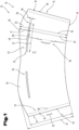
- Two flat blanks 13 are shown as examples of a variety of possible different shapes, wherein the blanks 13 can be wound into a cuff-shaped outer part 12 or into a jacket.
- the flat blank 13 has a substantially circular ring-segment-shaped basic shape, wherein the blank 13 has a first end section 14 and a second end section 15.
- the two end sections 14, 15 are preferably each aligned along an imaginary line to the circle center of the circular ring-segment-shaped basic shape.
- the blank 13 can be wound into a jacket.
- the first end section 14 and the second end section 15 can be coupled to one another in an overlap region 16.
- the end sections 14, 15 can be connected to one another in an overlap region 16 shown in a simplified manner. This can be done by a so-called overlap seam, by means of which the first end section 14 and the second end section 15 adhere to one another, for example by means of an adhesive layer 49.
- the first end section 14 of the blank 13 ends with a first longitudinal edge 17 and the second end section 15 in turn ends with a second longitudinal edge 18.
- the two longitudinal edges 17, 18 can preferably each be aligned along an imaginary line to the circle center of the circular ring segment-shaped basic shape.
- the blank 13 can have a longitudinal edge length 50 in the area of the first end section 14, in particular on the first longitudinal edge 17. When considering the longitudinal edge length 50, any shortening of the actual longitudinal edge length due to rounding or due to a bevel is disregarded here.
- the two longitudinal edges 17, 18 run approximately parallel to one another, with the overlapping area 16 being formed between them with an overlap width when viewed in the circumferential direction of the casing.
- the second end section 15 is folded over the first end section 14 on the outside. It goes without saying that an arrangement is also conceivable in which the first end section 14 is folded over the second end section 15 on the outside.
- the blank 13, or an outer part 12 formed from the blank 13, further comprises a first end face 19 and a second end face 20, wherein the first end face 19 and the second end face 20 are spaced apart from one another, wherein the blank 13 or the outer part 12 has a longitudinal extension 22 in a direction starting from the first end face 19 to the second end face 20.
- the end faces are preferably essentially concentric with respect to the circle center of the circular ring segment-shaped basic shape.
- the two end faces 19, 20, which are spaced apart from one another define an overall height 21 of the jacket when the outer part 12 is in the erected state. In particular when the jacket of the outer part 12 is conical, the overall height 21 corresponds geometrically to a height of the cone when viewed in axial section.
- the longitudinal extent 22 when viewed in axial section is geometrically the length of the jacket line.
- a cut 13 which is essentially in the shape of a segment of a circular ring is wound into a jacket, a conical jacket inevitably results.
- the maximum longitudinal extent 22 in the case of a conical jacket of the outer part 12 is generally greater than the overall height 21 of the jacket.
- the longitudinal axis 8 already described can also define the common longitudinal axis for the outer part 12, in particular when the outer part 12 is in its mounted position on the container 2.
- the overall height 21 of the shell is slightly lower than the container height 9 of the container 2 in the same spatial direction - namely in the direction of the longitudinal axis 8.
- the blank 13, or the outer part 12 formed from it has a receiving area 23 and an area 24, which area 24 is arranged between the receiving area 23 and the second end face 20 when viewed in the longitudinal extension 22.
- the receiving area 23 is designed as a recess, cutout, hole or as an opening in the blank 13 or in the outer part 12.
- the receiving area 23 shown has a first receiving area end 25 and a second receiving area end 26, wherein the first receiving area end 25 faces the first end section 14 of the blank 13 and wherein the second receiving area end 26 faces the second end section 15 of the blank 13, wherein the first receiving area end 25 and the second receiving area end 26 are spaced apart from one another.
- the receiving area 23 therefore has an elongated basic shape.
- the first receiving area end 25 and the second receiving area end 26 can be spaced apart by a length 27, which length 27 can be from 5% to 75% of a receiving area casing circumference of the casing.
- the receiving area 23 can have a circular ring segment-shaped basic shape, which is concentric with the circular ring segment-shaped basic shape of the blank 13.
- the receiving area 23 can further have a first receiving area front side 28, which first receiving area front side 28 faces the first front side 19 and wherein the Receiving area 23 has a second receiving area front side 29, which second receiving area front side 29 faces the second front side 20.
- the first receiving area front side 28 and the second receiving area front side 29 can be spaced apart from one another, wherein the receiving area 23 has a receiving area height 30 in a direction starting from the first receiving area front side 28 to the second receiving area front side 29.
- the receiving area height 30 can be adapted to the type and design of the container 2 to be encased, or the area 40, 41 to be accommodated.
- the second receiving area end face 29 facing the second end face 20 can be spaced apart from the second end face 20 by a first length 31 as viewed in the longitudinal extension 22 of the outer part 12.
- the second receiving area end face 29 facing the second end face 20 can be spaced apart from the first end face 19 by a second length 32 as viewed in the longitudinal extension 22 of the outer part 12.
- the maximum first length 31 and the maximum second length 32 or the sum of the two lengths 31, 32 can define a maximum annular segment height 33, which maximum annular segment height 33 corresponds in particular to a maximum longitudinal extension 22 or a maximum surface line of the conical outer part 12 or a maximum overall height 21.
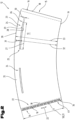
- the first end face 19 and the second end face 20 can be arranged as shown in the Fig.1 It can also be that the first end face 19 is circularly arc-shaped and that the second end face 20 is wave-shaped or sinusoidal. This is shown by way of example in the Fig.2 It goes without saying that these two designs are merely examples of various conceivable shapes. In any case, the first end face 19 and the second end face 20 essentially follow a circular arc shape and are essentially concentric with respect to a circle center of the circular ring segment-shaped basic shape.
- the one in the Fig.1 and 2 The blank 13 shown, or an outer part 12 formed therefrom, has a second receiving area 34 and a second area 35, which second area 35 is arranged between the second receiving area 34 and the second end face 20 when viewed in the longitudinal extension 22 of the outer part 12.
- the receiving area 23 and the second receiving area 34 are of the same dimensions in the examples shown.
- the two areas 24, 35 above the receiving areas 23, 34 are also of the same dimensions.
- the two blanks 13 shown are designed and symmetrical in such a way that the receiving area 23 and the second receiving area 34 are arranged opposite one another in the wound state, i.e. in the casing of the outer part 12.
- a predetermined separation area 36 is also provided.
- the predetermined separation area 36 is a so-called elevation, for example in the sense of WO 2020/245148 A1 of the applicant of the same name.
- the intended separation area 36 extends in a direction starting from the first end face 19 to the receiving area 23, in particular to the first receiving area end face 28.
- a further embodiment is shown, wherein the intended separation region 36 extends in a direction starting from the first end face 19 to the second end face 20.
- the intended separation region 36 is provided in the overlap region 16 of the end sections 14, 15 or the longitudinal edges 17, 18.
- the overlap region 16 can be designed, for example, as a detachable adhesive connection.
- a further exemplary embodiment of a blank 13 or an outer part 12 is shown, wherein the region 24 is formed with a fold line 37.
- the fold line 37 is, when viewed in the wound state, concentric to the jacket of the outer part 12 in relation to a longitudinal axis 8 of the casing of the outer part 12.
- the fold line 37 When viewed in the flat state, the fold line 37 is concentric with respect to the circle center of the circular ring-segment-shaped blank 13 or outer part 12.
- the region 24 between the fold line 37 and the second end face 20 has a fold region 38.
- the fold region 38 has a substantially round basic shape, which can at least approximately correspond to the circular cross-section in the region of the open end of the container to be covered.
- This folding area 38 can be folded inwards, in particular in the wound, jacket-shaped or conical state, in the radial direction towards the longitudinal axis 8 of the jacket of the outer part 12.
- the folding area 38 can have a tab 51, which tab 51 can be coupled, i.e. brought into engagement, with the second receiving area 34 which is opposite in the wound state.
- a combination packaging container 1 is shown as an example for a variety of possible different shapes, wherein the combination packaging container 1 is cup-shaped or bowl-shaped.
- the combination packaging container 1 is in the Fig.3 shown partially cut through the longitudinal axis 8.
- the combination packaging container 1 comprises a cup- or bowl-shaped container 2 with a base 3 and a container casing 4.
- the container 2 also has an open end 5 on its side facing away from the base 3.
- a flange 6 projecting outwards beyond the container casing 4 can be provided in the area of its open end 5.
- the base 3 forms a closed end 7 for the container casing 4.
- the container 2 has an essentially conical or truncated cone-shaped basic shape.
- the combination packaging container 1 When looking at the combination packaging container 1 in the front view shown, the combination packaging container 1 has a total height 10 which extends from the base 3 to the highest area of the second end face 20 of the outer part 12. The total height 10 is thus greater than the container height 9 and also greater than the construction height 21 of the outer part 12.
- the container 2 is preferably formed by a component produced in a deep-drawing process, which can be produced quickly and, above all, in a short cycle time.
- the deep-drawing process is well known and will therefore not be discussed in more detail.
- the deep-drawing process is particularly suitable for producing the container 2 with a sufficient wall thickness from a layer of a deformable material using a deep-drawing tool, which ensures tightness during storage, use and disposal.
- This manufacturing process enables the inner container 2 to have relatively thin walls.
- the container 2 can also be formed using other manufacturing processes, such as an injection molding process.
- a longitudinal axis 8 extends in the axial direction between the open end 5 and the end 7 closed with the base 3, which can also represent a central axis if the design is symmetrical.
- a closure element 39 for example a sealing plate, or to connect it to it.
- the flange 6 forms a sealing flange.
- the container 2 In the axial direction and thus in the direction of the longitudinal axis 8, the container 2 has a container height 9 between its open end 5, in particular the flange 6, and the bottom 3, whereby, depending on the cross-sectional dimensions, the receiving volume of the container 2 is determined.
- the container height 9 in conjunction with the cross-sectional dimensions thus defines a receiving space for the container 2.
- the container shell 4 is understood to be that section of the container 2 which extends between the open end 5, in particular the flange 6, and the base 3 in a predominantly axial direction.
- the container 2 with its container shell 4 is preferably designed in such a way that it tapers conically from the open end 5 to the base 3, i.e. is essentially frustoconical.
- the longitudinal axis 8 corresponds to the cone axis 42.
- the combination packaging container 1 further comprises an outer part 12 which is designed in the shape of a sleeve or jacket and surrounds the container 2 in the region of its container jacket 4 at least in sections or regions.
- the sleeve-shaped outer part 12 is preferably made of a cellulose material, such as a cardboard material, with sufficient strength in relation to the absorption and transmission of in particular axially acting pressure forces and is wound from a flat blank 13 to form a jacket.
- the blank 13 is usually printed in its undeformed flat position and optionally provided with an additional coating.
- a cellulose material is usually used as the material for the blank 13, although this can also be cardboard or strong paper produced using a recycling process. If a layer or ply of the outer part 12 is made of a recycled material, an additional layer made of a higher quality paper can be arranged on or connected to at least one of the surfaces. This additional layer is used to ensure perfect printing for the production of decorations, labels and product information.
- the sleeve-like or jacket-like outer part 12 leads to an additional reinforcement or stiffening effect of the container 2 and thus of the entire combination packaging container 1. This provides, on the one hand, high strength and good thermal insulation and, on the other hand, optimal light protection for the contents of the packaging container.
- the cardboard is additionally coated or sealed with a water-repellent material in the area of the cut edges. This is particularly advantageous if the combination packaging container 1 is subject to increased are exposed to moisture. Coating the cardboard used for the outer part 12 with a water-repellent layer prevents the cardboard from swelling in a humid environment and ultimately becoming detached from the container casing 4 of the combination packaging container 1.
- the container 2 can preferably be a reusable container, which in particular is or comprises a plastic material or a recycled plastic material.
- the container 2 has an alignment means 52 in the region of its bottom 3, in particular as in the Fig.3 schematically shown has a groove or an elevation which is designed for fixing and/or positioning the container 2.
- the casing of the outer part 12 has a receiving area 23 and an area 24, which area 24 is arranged between the receiving area 23 and the second end face 20 when viewed in the longitudinal extension 22.
- the outer part 12 is wound around the container 2 so that an area 40 of the open end 5 and an area 41 of the closure element 39 of the container 2 are received in the receiving area 23 of the casing of the outer part 12.
- the areas 40, 41 and a part of the flange 6 or a part of a collar 45 protrude beyond the casing of the outer part 12 in an imaginary, shortest straight connecting line between the longitudinal axis 8 or the cone axis 42 and the areas 40, 41 when viewing the combination packaging container 1 in axial section.
- the region 24 of the outer part 12, viewed in the longitudinal extension 22, can extend beyond the open end 5 of the container 2, i.e. projects beyond the open end 5 and the closure element 39.
- the closure element 39 is designed or arranged in such a way that removal is only possible after removal of the outer part 12 from the container 2. This is shown in the embodiment shown in the Fig.3 realized in that the closure element 39 is partially received in the receiving areas 23, 34.
- closure element 39 is connected to the casing of the outer part 12, and that the closure element 39 is so is designed such that removal is possible at the same time as removal of the outer part 12 from the container 2.
- the closure element 39 can be designed as a sealing plate, which sealing plate can be glued or otherwise connected to the casing of the outer part 12, so that the sealing plate is also removed when the outer part 12 is separated.
- the jacket of the outer part 12 can extend over a part of the container jacket 4.
- the jacket of the outer part 12 extends over a part of the container jacket 4, which corresponds to a quarter to two thirds of the container jacket 4.
- Outer parts 12 are shown with different high surface lines or different maximum longitudinal extensions 22. Consequently, the parts of the container 2 visible to an observer are of different sizes.
- the container shell 4 of the container 2 and the shell of the outer part 12 can be as shown in the Fig. 3 to 6 shown be essentially frustoconical and arranged around a common cone axis 42.
- a first angle 43 between the container shell 4 of the container 2 and the cone axis 42 is larger than a second angle 44 between the shell of the outer part 12 and the cone axis 42.
- Fig.3 shown partial axial section that the open end 5 and the closure element 39 have a collar 45 projecting over the container shell 4 of the container 2 in the radial direction to the cone axis 42, wherein a third angle 48 is formed between the cone axis 42 and an imaginary cutting line 46, which imaginary cutting line 46 extends from an outermost point of the collar 45 to the cone axis 42 and intersects the first end face 19, wherein the third angle 48 is larger than the second angle 44.
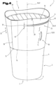
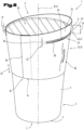
- Fig. 4 to 6 each show a three-dimensional view of an embodiment of a combination packaging container 1, whereby the examples are to be understood as representative of a large number of conceivable shapes. Reference is made to the above In order to avoid unnecessary repetition, special features of the variants shown are discussed below.
- the Indian Fig.4 The combination packaging container 1 shown is covered with an outer part 12 which has a wave-shaped second end face 20.
- the container 2 is closed with a closure element 39 designed as a sealing plate or film, and a collar 45 or a flange 6 in the area of the open end 5 protrude in the radial direction to the longitudinal axis 8 or to the cone axis 42 from the receiving area 23 of the outer part 12.
- a predetermined separation region 36 is provided below the receiving region 23, which extends along the surface line in the longitudinal extension 22 from the first end face 19 to the first receiving region end face 28.
- the Indian Fig.5 The combination packaging container 1 shown is also covered with an outer part 12, whereby the outer part 12 is smaller than the outer part 12 shown in the Fig.4 shown example is longer, and thus encases or covers a larger part of the container 2.
- the second end face 20 is also wave-shaped, but has a smaller Fig.4 two instead of three wave crests or elevations.
- the Fig.5 It can also be seen that a second receiving area 34 is provided, from which the collar 45 or the flange 6 of the container 2 protrudes.
- FIG.6 another combination packaging container 1 is shown, which is also covered with an outer part 12.
- the second end face 20 of the outer part 12 is also wave-shaped here, but only has one wave crest or an elevation.
- the area 24 above the receiving area 23, i.e. the first length 31, is larger than the second area 35 above the second receiving area 34, or the first length 31 formed above it.
- the container 2 can be fixed and/or positioned in the region of the bottom 3 of the container 2 by coupling a coupling element to an alignment means 52, in particular to a groove or to an elevation, before being wrapped with the outer part 12 or before the outer part 12 is pushed on axially.
Abstract
Die Erfindung betrifft einen Kombi-Verpackungsbehälter (1) mit einem becherförmigen Behälter (2) und einem Außenteil (12). Der Mantel des Außenteils (12) weist einen Aufnahmebereich (23) und einen Bereich (24) auf, welcher Bereich (24) in Längserstreckung (22) betrachtet zwischen dem Aufnahmebereich (23) und der zweiten Stirnseite (20) angeordnet ist. Ein Bereich (40) des offenen Endes (5) und/oder ein Bereich (41) des Verschlusselements (39) des Behälters (2) ist in dem Aufnahmebereich (23) des Mantels des Außenteils (12) aufgenommen. Die Erfindung betrifft weiters ein Verfahren zur Herstellung eines Kombi-Verpackungsbehälters (1) und ein Verfahren zum Öffnen eines Kombi-Verpackungsbehälters (1).The invention relates to a combination packaging container (1) with a cup-shaped container (2) and an outer part (12). The casing of the outer part (12) has a receiving area (23) and an area (24), which area (24) is arranged between the receiving area (23) and the second end face (20) when viewed in the longitudinal extension (22). An area (40) of the open end (5) and/or an area (41) of the closure element (39) of the container (2) is received in the receiving area (23) of the casing of the outer part (12). The invention further relates to a method for producing a combination packaging container (1) and a method for opening a combination packaging container (1).
Description
Die Erfindung betrifft einen Zuschnitt, sowie ein aus einem Zuschnitt gebildetes manschettenförmiges Außenteil zum Ummanteln eines becherförmigen Behälters, sowie einen aus einem Behälter und einem Außenteil gebildeten Kombi-Verpackungsbehälter. Die Erfindung betrifft weiters noch ein Verfahren zur Herstellung eines Kombi-Verpackungsbehälters, sowie ein Verfahren zum Öffnen eines Kombi-Verpackungsbehälters.The invention relates to a blank, as well as a sleeve-shaped outer part formed from a blank for encasing a cup-shaped container, as well as a combination packaging container formed from a container and an outer part. The invention further relates to a method for producing a combination packaging container, as well as a method for opening a combination packaging container.
Aufgrund von immer höheren Umweltanforderungen an Produkte und Produktverpackungen wird es immer wichtiger, ein Recyceln, und zusätzlich zu einem Recyceln auch ein Wiederverwenden zu ermöglichen. Beim Recyclen soll eine sortenreine Trennung der verschiedenen Materialien möglich sein, um die Recyclingqualität zu verbessern. Insbesondere soll hierbei die sortenreine Trennung der verschiedenen Materialien möglichst einfach gestaltet werden, sodass etwaige Versäumnisse bzw. Fehler eines Menschen beim Recyclingvorgang möglichst kompensiert werden können. Darüber hinaus sollen gebrauchte Produkte und Produktverpackungen auf einfache und nachhaltige Art und Weise zu wiederverwendbaren Produkten und Produktverpackungen verarbeitet werden.Due to ever-increasing environmental requirements for products and product packaging, it is becoming increasingly important to enable recycling and, in addition to recycling, reuse. When recycling, it should be possible to separate the different materials by type in order to improve the recycling quality. In particular, the separation of the different materials by type should be made as simple as possible so that any human oversights or errors during the recycling process can be compensated for as far as possible. In addition, used products and product packaging should be processed into reusable products and product packaging in a simple and sustainable manner.
Die
Aufgabe der vorliegenden Erfindung war es, die Nachteile des Standes der Technik zu überwinden und einen Zuschnitt, ein Außenteil sowie einen Kombi-Verpackungsbehälter zur Verfügung zu stellen, bei dem das manschettenförmige Außenteil für Recyclingzwecke einfach vom Behälter entfernt werden kann, und bei dem sichergestellt ist, dass ein Benutzer diese Trennung vornimmt.The object of the present invention was to overcome the disadvantages of the prior art and to provide a blank, an outer part and a combination packaging container in which the sleeve-shaped outer part can be easily removed from the container for recycling purposes and in which it is ensured that a user carries out this separation.
Diese Aufgabe wird durch eine Vorrichtung und ein Verfahren gemäß den Ansprüchen gelöst.This object is achieved by a device and a method according to the claims.
Die Erfindung betrifft einen Zuschnitt für ein Außenteil zum Ummanteln eines becherförmigen Behälters, welcher einen Behältermantel aufweist, der ein offenes Ende und ein mit einem Boden verschlossenes Ende aufweist, wobei der Zuschnitt eine im Wesentlichen kreisringsegmentförmige Grundform aufweist, wobei der Zuschnitt einen ersten Endabschnitt und einen zweiten Endabschnitt aufweist, wobei der Zuschnitt zu einem Mantel wickelbar ist und dabei der erste Endabschnitt und der zweite Endabschnitt miteinander in einem Überlappungsbereich koppelbar sind, wobei der Zuschnitt weiters eine erste Stirnseite und eine zweite Stirnseite aufweist und die erste Stirnseite und die zweite Stirnseite voneinander beabstandet sind, wobei der Zuschnitt eine Längserstreckung in einer Richtung ausgehend von der ersten Stirnseite zur zweiten Stirnseite aufweist.The invention relates to a blank for an outer part for covering a cup-shaped container, which has a container jacket that has an open end and an end closed with a base, wherein the blank has a substantially circular ring-segment-shaped basic shape, wherein the blank has a first end section and a second end section, wherein the blank can be wound into a jacket and the first end section and the second end section can be coupled to one another in an overlapping region, wherein the blank further has a first end face and a second end face and the first end face and the second end face are spaced apart from one another, wherein the blank has a longitudinal extension in a direction starting from the first end face to the second end face.
Der Zuschnitt weist einen Aufnahmebereich und einen Bereich auf, welcher Bereich in Längserstreckung betrachtet zwischen dem Aufnahmebereich und der zweiten Stirnseite angeordnet ist.The blank has a receiving area and an area, which area, viewed in longitudinal extension, is arranged between the receiving area and the second end face.
Der erfindungsgemäße Zuschnitt bringt den überraschenden Vorteil mit sich, dass durch den Aufnahmebereich und den Bereich, welcher in Längserstreckung betrachtet zwischen dem Aufnahmebereich und der zweiten Stirnseite angeordnet ist, erreicht werden kann, dass der Zuschnitt und ein mit dem Zuschnitt umwickelter becherförmiger Behälter voneinander getrennt werden müssen, um einen Zugriff zu einem in dem Behälter umfassten Füllgut zu ermöglichen. Dadurch kann eine verbesserte Trennung und ein verbessertes Recycling gewährleistet werden. Zudem kann der Zuschnitt eine hochwertige und ansprechende Umverpackung eines Behälters bilden, wobei der Zuschnitt zudem eine Funktion als Originalitätsnachweis erfüllen kann und damit als "tamper evident" gilt.The blank according to the invention has the surprising advantage that the receiving area and the area which, viewed in the longitudinal direction, is arranged between the receiving area and the second end face make it possible to ensure that the blank and a cup-shaped container wrapped with the blank have to be separated from one another in order to enable access to a filling material contained in the container. This can ensure improved separation and recycling. In addition, the blank can form high-quality and attractive outer packaging for a container, whereby the blank can also fulfill a function as proof of originality and is therefore considered "tamper evident".
Der Zuschnitt ist insbesondere, jedoch nicht ausschließlich, zum Ummanteln von wiederverwendbaren Behältern, insbesondere von wiederverwendbaren Kunststoff-Behältern geeignet. Der Zuschnitt kann nach dem für eine Nutzung eines Behälters erforderlichen Abtrennen vom umwickelten Behälter weitgehend sortenrein einem Recycling zugeführt werden, während ein Behälter einem Wiederverwendungsprozess unterzogen werden kann.The cut is particularly, but not exclusively, suitable for wrapping reusable containers, especially reusable plastic containers. After the separation from the wrapped container required for use of a container, the cut can be recycled in a largely pure form, while a container can be subjected to a reuse process.
Bei dem Zuschnitt kann es sich um eine aus einem Bogen oder einem blattförmigen Element zugeschnittenes Teil handeln, beispielsweise aus einem Papier, Karton, oder auch aus einem dünnen Kunststoffbogen. Insbesondere kann es sich bei dem Aufnahmebereich um einen Ausschnitt, ein Loch oder um einen Durchbruch in dem Zuschnitt handeln. Der Aufnahmebereich kann aus dem Zuschnitt beispielsweise herausgeschnitten oder herausgestanzt werden. Es ist auch denkbar, dass der Aufnahmebereich einen länglichen Schlitz umfasst bzw. ein länglicher Schlitz ist, durch welchen ein Siegelrand, Kragen oder ähnliches eines Behälters durchführbar ist.The cut-out can be a part cut from a sheet or a sheet-like element, for example from paper, cardboard, or even from a thin plastic sheet. In particular, the receiving area can be a This can be a cutout, a hole or an opening in the blank. The receiving area can be cut or punched out of the blank, for example. It is also conceivable that the receiving area comprises an elongated slot or is an elongated slot through which a sealing edge, collar or similar of a container can be passed.
Die Erfindung betrifft auch ein Außenteil zum Ummanteln eines becherförmigen Behälters, welcher einen Behältermantel aufweist, der ein offenes Ende und ein mit einem Boden verschlossenes Ende aufweist, wobei das Außenteil aus einem Zuschnitt gebildet ist, welcher Zuschnitt eine im Wesentlichen kreisringsegmentförmige Grundform aufweist, welcher Zuschnitt einen ersten Endabschnitt und einen zweiten Endabschnitt aufweist, wobei der Zuschnitt zu einem Mantel gewickelt ist und dabei der erste Endabschnitt und der zweite Endabschnitt in einem Überlappungsbereich miteinander gekoppelt sind, wobei das Außenteil weiters eine erste Stirnseite und eine zweite Stirnseite aufweist und die erste Stirnseite und die zweite Stirnseite voneinander beabstandet sind, wobei das Außenteil eine Längserstreckung in einer Richtung ausgehend von der ersten Stirnseite zur zweiten Stirnseite aufweist.The invention also relates to an outer part for covering a cup-shaped container, which has a container jacket that has an open end and an end closed with a bottom, wherein the outer part is formed from a blank, which blank has a substantially circular ring-segment-shaped basic shape, which blank has a first end section and a second end section, wherein the blank is wound into a jacket and the first end section and the second end section are coupled to one another in an overlapping region, wherein the outer part further has a first end face and a second end face and the first end face and the second end face are spaced apart from one another, wherein the outer part has a longitudinal extension in a direction starting from the first end face to the second end face.
Der Mantel des Außenteils weist einen Aufnahmebereich und einen Bereich auf, welcher Bereich in Längserstreckung betrachtet zwischen dem Aufnahmebereich und der zweiten Stirnseite angeordnet ist.The casing of the outer part has a receiving area and a region, which region, viewed in the longitudinal extension, is arranged between the receiving area and the second end face.
Der erfindungsgemäße Außenteil bringt den überraschenden Vorteil mit sich, dass durch den Aufnahmebereich und den Bereich, welcher in Längserstreckung betrachtet zwischen dem Aufnahmebereich und der zweiten Stirnseite angeordnet ist, erreicht werden kann, dass der Außenteil und ein mit dem Außenteil umwickelter becherförmiger Behälter voneinander getrennt werden müssen, um einen Zugriff zu einem in dem Behälter umfassten Füllgut zu ermöglichen. Dadurch kann eine verbesserte Trennung und ein verbessertes Recycling gewährleistet werden. Zudem kann der Außenteil eine hochwertige und ansprechende Umverpackung eines Behälters bilden, wobei der Außenteil zudem eine Funktion als Originalitätsnachweis erfüllen kann und damit als "tamper evident" gilt.The outer part according to the invention has the surprising advantage that the receiving area and the area which, viewed in the longitudinal direction, is arranged between the receiving area and the second end face make it possible to ensure that the outer part and a cup-shaped container wrapped with the outer part have to be separated from one another in order to enable access to a filling material contained in the container. This can ensure improved separation and recycling. In addition, the outer part can form high-quality and attractive outer packaging for a container, whereby the outer part can also fulfill a function as proof of originality and is therefore considered "tamper evident".
Der Außenteil ist insbesondere, jedoch nicht ausschließlich, zum Ummanteln von wiederverwendbaren Behältern, insbesondere von wiederverwendbaren Kunststoff-Behältern geeignet. Der Außenteil kann nach dem für eine Nutzung eines Behälters erforderlichen Abtrennen vom umwickelten Behälter weitgehend sortenrein einem Recycling zugeführt werden, während ein Behälter einem Wiederverwendungsprozess unterzogen werden kann.The outer part is particularly, but not exclusively, suitable for covering reusable containers, in particular reusable plastic containers. The outer part can be removed from the container after it has been separated from the Wrapped containers can be recycled in a largely pure form, while a container can be subjected to a reuse process.
Ferner kann vorgesehen sein, dass der Aufnahmebereich ein erstes Aufnahmebereich-Ende und ein zweites Aufnahmebereich-Ende aufweist, wobei das erste Aufnahmebereich-Ende dem ersten Endabschnitt des Zuschnitts zugewandt ist und wobei das zweite Aufnahmebereich-Ende dem zweiten Endabschnitt des Zu-schnitts zugewandt ist, wobei das erste Aufnahmebereich-Ende und das zweite Aufnahmebereich-Ende voneinander beabstandet sind.Furthermore, it can be provided that the receiving area has a first receiving area end and a second receiving area end, wherein the first receiving area end faces the first end portion of the blank and wherein the second receiving area end faces the second end portion of the blank, wherein the first receiving area end and the second receiving area end are spaced apart from one another.
Dies bringt den Vorteil mit sich, dass dadurch ein Aufnahmebereich, also beispielsweise ein Durchbruch, eine Ausnehmung oder ein Loch, mit einer Geometrie geschaffen wird, welche einfach gefertigt werden kann und welche gut zur Aufnahme von Bereichen eines Behälters, sowie zur Umverpackung eines Behälters, geeignet ist.This has the advantage that it creates a receiving area, for example an opening, a recess or a hole, with a geometry that can be easily manufactured and which is well suited for receiving areas of a container, as well as for repackaging a container.
Für den Fachmann ist klar, dass es auch sein kann, dass erste Aufnahmebereich-Ende dem ersten Endabschnitt des Außenteils zugewandt ist und wobei das zweite Aufnahmebereich-Ende dem zweiten Endabschnitt des Außenteils zugewandt ist, wobei das erste Aufnahmebereich-Ende und das zweite Aufnahmebereich-Ende voneinander beabstandet sind. Dies sei nur beispielhaft für die Verwendung der Bezeichnungen Zuschnitt und Außenteil in diesem Dokument genannt. Eben weil das Außenteil durch einen Zuschnitt gebildet ist, können die beiden Begriffe eine synonyme Bedeutung haben. Dies insbesondere, wenn der Zuschnitt zu einem Mantel gewickelt ist und dadurch ein manschettenförmiges Außenteil bildet.It is clear to the person skilled in the art that it can also be the case that the first receiving area end faces the first end section of the outer part and the second receiving area end faces the second end section of the outer part, the first receiving area end and the second receiving area end being spaced apart from one another. This is only an example of the use of the terms blank and outer part in this document. Precisely because the outer part is formed by a blank, the two terms can have a synonymous meaning. This is particularly the case when the blank is wound into a sheath and thus forms a cuff-shaped outer part.
Darüber hinaus kann vorgesehen sein, dass das erste Aufnahmebereich-Ende und das zweite Aufnahmebereich-Ende durch eine Aufnahmebereichs-Länge voneinander beabstandet sind, welche Länge von 5% bis 75%, bevorzugt von 5% bis 50%, eines Aufnahmebereichs-Mantelumfangs des Mantels beträgt. Bei mehreren Aufnahmebereichen kann eine Summe aller Aufnahmebereichs-Längen von 5% bis 75%, bevorzugt von 5% bis 50%, betragen. Mit Aufnahmebereichs-Mantelumfang ist dabei der Umfang des Kreisquerschnitts gemeint, welcher Kreisquerschnitt bei Betrachtung des zu einem Mantel gewickelten Außenteils 90° durch den Aufnahmebereich zur Mantelachse liegt. Zweckmäßigerweise ist der Aufnahmebereichs-Mantelumfang gleich groß oder geringfügig größer, als der maximale Umfang eines zu ummantelnden Behälters, respektive dessen maximalen Umfangs im Bereich des offenen Endes.Furthermore, it can be provided that the first receiving area end and the second receiving area end are spaced apart from one another by a receiving area length, which is from 5% to 75%, preferably from 5% to 50%, of a receiving area casing circumference of the casing. In the case of several receiving areas, a sum of all receiving area lengths can be from 5% to 75%, preferably from 5% to 50%. The receiving area casing circumference here means the circumference of the circular cross-section, which circular cross-section lies 90° through the receiving area to the casing axis when looking at the outer part wound into a casing. The receiving area casing circumference is expediently the same size or slightly larger than the maximum circumference of a container to be encased, or its maximum circumference in the area of the open end.
Diese Ausformung des Aufnahmebereichs bringt den Vorteil mit sich, dass eine Aufnahme eines Behälters, respektive eine Aufnahme von Bereichen eines Behälters zuverlässig ermöglicht sein kann. Die genaue Länge, also ein Absolutwert der Länge ist dabei abhängig von der Form und Größe des mit dem Außenteil zu ummantelnden Behälters, und dabei vor allem vom maximalen Durchmesser oder Umfang des offenen Endes. Insbesondere wenn mehrere Aufnahmebereiche vorgesehen sind, kann eine Länge der einzelnen Aufnahmebereiche geringer ausfallen.This shape of the receiving area has the advantage that it is possible to reliably accommodate a container or areas of a container. The exact length, i.e. an absolute value of the length, depends on the shape and size of the container to be covered with the outer part, and in particular on the maximum diameter or circumference of the open end. In particular, if several receiving areas are provided, the length of the individual receiving areas can be shorter.
Vorteilhaft ist auch eine Ausprägung, gemäß welcher vorgesehen sein kann, dass der Aufnahmebereich eine kreisringsegmentförmige Grundform aufweist, welche konzentrisch mit der kreisringsegmentförmige Grundform des Zuschnitts ist, und dass der Aufnahmebereich eine erste Aufnahmebereich-Stirnseite aufweist, welche erste Aufnahmebereich-Stirnseite der ersten Stirnseite zugewandt ist und wobei der Aufnahmebereich eine zweite Aufnahmebereich-Stirnseite aufweist, welche zweite Aufnahmebereich-Stirnseite der zweiten Stirnseite zugewandt ist, wobei die erste Aufnahmebereich-Stirnseite und die zweite Aufnahmebereich-Stirnseite voneinander beabstandet sind, wobei der Aufnahmebereich eine Aufnahme-bereichshöhe in einer Richtung ausgehend von der ersten Aufnahmebereich-Stirnseite zur zweiten Aufnahmebereich-Stirnseite aufweist.Also advantageous is a form according to which it can be provided that the receiving area has a circular ring segment-shaped basic shape which is concentric with the circular ring segment-shaped basic shape of the blank, and that the receiving area has a first receiving area front side, which first receiving area front side faces the first front side, and wherein the receiving area has a second receiving area front side, which second receiving area front side faces the second front side, wherein the first receiving area front side and the second receiving area front side are spaced apart from one another, wherein the receiving area has a receiving area height in a direction starting from the first receiving area front side to the second receiving area front side.
Diese Ausformung des Aufnahmebereichs bringt den Vorteil mit sich, dass eine Aufnahme eines Behälters zuverlässig ermöglicht sein kann. Zudem kann eine derartige Ausgestaltung auch vergleichsweise einfach und kosteneffizient herstellbar sein. Die kreisringsegmentförmige Grundform des Aufnahmebereichs bedingt, dass die erste Aufnahmebereich-Stirnseite kürzer ist als die zweite Aufnahmebereich-Stirnseite. Dadurch kann in einem mantelförmigen bzw. manschettenförmigen Zustand des Außenteils gewährleistet sein, dass der Aufnahmebereich zur Aufnahme eines Behälters oder von Bereichen eines Behälters besonders gut geeignet ist. Eine Distanz der beiden Stirnseiten zueinander, also eine Aufnahmebereichs-Höhe kann vorteilhafterweise konstant sein. Zweckmäßigerweise entspricht eine Aufnahmebereichs-Höhe der Höhe eines zur Aufnahme in dem Aufnahmebereich vorgesehenen Bereichs eines Behälters, beispielsweise eines Flansches inklusive Verschlusselement, wie Siegelplatine, Deckel oder ähnlichem. Besonders zweckmäßig ist hierbei, wenn die Aufnahmebereichs-Höhe geringfügig größer ist als der zur Aufnahme vorgesehenen Bereichs eines Behälters.This shape of the receiving area has the advantage that it can reliably accommodate a container. In addition, such a design can also be produced comparatively simply and cost-effectively. The circular ring-segment-shaped basic shape of the receiving area means that the first receiving area front side is shorter than the second receiving area front side. This can ensure that the receiving area is particularly well suited to accommodating a container or areas of a container in a jacket-shaped or cuff-shaped state of the outer part. A distance between the two front sides, i.e. a receiving area height, can advantageously be constant. A receiving area height expediently corresponds to the height of an area of a container intended for accommodation in the receiving area, for example a flange including a closure element such as a sealing plate, lid or similar. It is particularly expedient if the receiving area height is slightly larger than the area of a container intended for accommodation.
Gemäß einer Weiterbildung ist es möglich, dass die der zweiten Stirnseite zugewandte zweite Aufnahmebereich-Stirnseite in Längserstreckung des Außenteils betrachtet durch eine erste Länge von der zweiten Stirnseite beabstandet ist. Die erste Länge definiert damit quasi eine Höhe des Bereichs, welcher über dem Aufnahmebereich liegt. Wenn das Außenteil um einen Behälter gewickelt ist und damit einen Behälter ummantelt, kann der Bereich mit seiner ersten Länge oder mit einem Teil seiner ersten Länge das obere Ende des Behälters überragen. Dabei kann es auch sein, dass die erste Länge variiert. Dies insbesondere, wenn die zweite Stirnseite des Außenteils keiner exakten Kreisbogenform folgt, sondern beispielsweise wellenförmig ausgebildet ist.According to a further development, it is possible for the second receiving area front side facing the second front side to be spaced apart from the second front side by a first length when viewed in the longitudinal extension of the outer part. The first length thus defines a height of the area that lies above the receiving area. If the outer part is wrapped around a container and thus encases a container, the area can protrude beyond the upper end of the container with its first length or with part of its first length. The first length can also vary. This is particularly the case if the second front side of the outer part does not follow an exact circular arc shape, but is, for example, wave-shaped.
Ferner kann es zweckmäßig sein, wenn die der zweiten Stirnseite zugewandte zweite Aufnahmebereich-Stirnseite in Längserstreckung des Außenteils betrachtet durch eine zweite Länge von der ersten Stirnseite beabstandet ist. Dabei kann es auch sein, dass die zweite Länge variiert. Dies insbesondere, wenn die erste Stirnseite des Außenteils keiner exakten Kreisbogenform folgt, sondern beispielsweise wellenförmig ausgebildet ist. Hierbei hat es sich auch als zweckmäßig erwiesen, dass die die zweite Länge größer ist als die erste Länge.Furthermore, it can be expedient if the second receiving area end face facing the second end face is spaced apart from the first end face by a second length when viewed in the longitudinal extension of the outer part. The second length can also vary. This is particularly the case if the first end face of the outer part does not follow an exact circular arc shape, but is, for example, wave-shaped. In this case, it has also proven expedient for the second length to be greater than the first length.
Darüber hinaus kann vorgesehen sein, dass die maximale erste Länge und die maximale zweite Länge eine maximale Kreisringsegmenthöhe definieren, welche Kreisringsegmenthöhe insbesondere einer maximalen Längserstreckung des Außenteils oder einer maximalen Bauhöhe entspricht.Furthermore, it can be provided that the maximum first length and the maximum second length define a maximum annular segment height, which annular segment height corresponds in particular to a maximum longitudinal extension of the outer part or a maximum construction height.
Des Weiteren kann vorgesehen sein, dass die erste Stirnseite und/oder die zweite Stirnseite kreisbogenförmig ausgebildet sind, oder dass die erste Stirnseite und/oder die zweite Stirnseite wellen- oder sinuskurvenförmig ausgebildet sind.Furthermore, it can be provided that the first end face and/or the second end face are formed in the shape of a circular arc, or that the first end face and/or the second end face are formed in the shape of a wave or sinusoidal curve.
Dies bringt den Vorteil mit sich, dass ein derart geformter Außenteil besonders gut zum Umwickeln eines Behälters geeignet sein kann. Zudem kann eine optische Erscheinung damit ansprechend und individuell gestaltbar sein. Dies gilt natürlich für das Außenteil in seinem Zustand als Zuschnitt bzw. in seinem noch nicht zu einem Mantel oder zu einer Manschette gewickelten Zustand. Wenn das Außenteil zu einem Mantel oder zu einer Manschette gewickelt ist, sind die erste und die zweite Stirnseite vorteilhafterweise parallel oder zumindest im Wesentlichen parallel zueinander angeordnet. Es hat sich auch als vorteilhaft erwiesen, dass wellen- oder sinuskurvenförmige Stirnseiten im Wesentlichen einer Kreisbogenform folgen, respektive der kreisringsegmentförmigen Grundform des Außenteils folgen. Eine gewisse Konzentrizität der Ausgestaltung hat sich als zweckmäßig herausgestellt.This has the advantage that an outer part shaped in this way can be particularly well suited for wrapping around a container. In addition, a visual appearance can be attractive and individually designed. This naturally applies to the outer part in its state as a cut or in its state in which it has not yet been wound into a jacket or a sleeve. When the outer part is wound into a jacket or a sleeve, the first and second end faces are advantageously arranged parallel or at least essentially parallel to one another. It has also proven to be advantageous for wave-shaped or sinusoidal end faces to essentially follow a circular arc shape. or follow the circular ring-segment-shaped basic shape of the outer part. A certain concentricity of the design has proven to be useful.
Es ist auch denkbar, dass die erste Aufnahmebereich-Stirnseite und/oder die zweite Aufnahmebereich-Stirnseite kreisbogenförmig ausgebildet sind, oder dass die erste Aufnahmebereich-Stirnseite und/oder die zweite Aufnahmebereich-Stirnseite wellen- oder sinuskurvenförmig ausgebildet sind.It is also conceivable that the first receiving area front side and/or the second receiving area front side are formed in the shape of a circular arc, or that the first receiving area front side and/or the second receiving area front side are formed in the shape of a wave or sinusoid.
Gemäß einer besonderen Ausprägung ist es möglich, dass der Mantel des Außenteils einen zweiten Aufnahmebereich und einen zweiten Bereich aufweist, welcher zweite Bereich in Längserstreckung des Außenteils betrachtet zwischen dem zweiten Aufnahmebereich und der zweiten Stirnseite angeordnet ist.According to a particular embodiment, it is possible for the casing of the outer part to have a second receiving region and a second region, which second region is arranged between the second receiving region and the second end face, viewed in the longitudinal extension of the outer part.
Dies bringt den Vorteil mit sich, dass sich zwei Aufnahmebereiche als besonders geeignet erwiesen haben, um Behälter bestimmter Geometrien zuverlässig zu umwickeln, respektive bereichsweise aufzunehmen. Vorteilhafterweise liegen die beiden Aufnahmebereiche bei Betrachtung des manschettenförmigen Außenteils in Umfangsrichtung zumindest im Wesentlichen auf demselben Umfang bzw. auf derselben Höhe. Die beiden Aufnahmebereiche können dabei dieselbe Grundform, aber auch eine unterschiedliche Grundform aufweisen. Der Bereich und der zweite Bereich können in Umfangsrichtung, also zwischen der zweiten Stirnseite und der jeweiligen Aufnahmebereich-Stirnseite, dieselbe Höhe haben. Es sind aber ebenso unterschiedliche Höhen denkbar.This has the advantage that two receiving areas have proven to be particularly suitable for reliably wrapping containers of certain geometries or for receiving them in certain areas. Advantageously, when looking at the sleeve-shaped outer part, the two receiving areas are at least essentially on the same circumference or at the same height in the circumferential direction. The two receiving areas can have the same basic shape or a different basic shape. The area and the second area can have the same height in the circumferential direction, i.e. between the second end face and the respective receiving area end face. However, different heights are also conceivable.
Entsprechend einer vorteilhaften Weiterbildung kann vorgesehen sein, dass der Aufnahmebereich und der zweite Aufnahmebereich zumindest im Wesentlichen gleich dimensioniert sind, und dass der Aufnahmebereich und der zweite Aufnahmebereich im Mantels des Außenteils einander gegenüberliegend angeordnet sind.According to an advantageous development, it can be provided that the receiving area and the second receiving area are at least substantially of the same dimension, and that the receiving area and the second receiving area are arranged opposite one another in the casing of the outer part.
Dies bringt den Vorteil mit sich, dass dadurch eine im Wesentlichen symmetrische Anordnung der Aufnahmebereiche und Bereiche erzielbar ist. Dies kann sowohl im Hinblick auf eine optische Erscheinung, als auch in Bezug auf eine Funktionalität vorteilhaft sein. Es ist auch denkbar, dass weitere gleichartig dimensionierte oder auch verschieden ausgeformte Aufnahmebereiche vorgesehen sind.This has the advantage that an essentially symmetrical arrangement of the receiving areas and areas can be achieved. This can be advantageous both in terms of visual appearance and in terms of functionality. It is also conceivable that further receiving areas of the same size or of different shapes are provided.
Insbesondere kann es vorteilhaft sein, dass im Mantel des Außenteils ein Solltrennbereich vorgesehen ist, welcher Solltrennbereich sich in einer Richtung ausgehend von der ersten Stirnseite zum Aufnahmebereich, insbesondere zur ersten Aufnahmebereich-Stirnseite, erstreckt oder welcher Solltrennbereich sich in einer Richtung ausgehend von der ersten Stirnseite bis zur zweiten Stirnseite erstreckt.In particular, it can be advantageous that a predetermined separation region is provided in the casing of the outer part, which predetermined separation region extends in a direction starting from the first end face to the receiving region, in particular to the first receiving region end face, or which predetermined separation region extends in a direction starting from the first end face to the second end face.
Dies bringt den Vorteil mit sich, dass durch das Vorsehen eines Solltrennbereichs ein Trennen des Außenteils von einem Behälter erleichtert wird. Insbesondere ein Solltrennbereich welcher entlang der obenstehend beschriebenen zweiten Länge ausgebildet ist, kann vorteilhaft sein. Dabei kann es ausreichend sein, wenn sich der Solltrennbereich nicht über die gesamte Längserstreckung bzw. Bauhöhe des Mantels des Außenteils erstreckt, sondern sich lediglich von der unteren ersten Stirnseite hin zur ersten Aufnahmebereich-Stirnseite erstreckt. Es ist auch denkbar, dass der Solltrennbereich dergestalt ausgebildet ist, dass bei einem Trennen des Solltrennbereichs nicht das gesamte Außenteil abgetrennt wird, sondern dass dieses partiell auf dem Behälter verbleibt, aber ein Benutzer dennoch Zugriff auf den Behälterinhalt erhält, respektive ein Verschlusselement nach dem partiellen Abtrennen entfernbar ist.This has the advantage that the provision of a predetermined separation area makes it easier to separate the outer part from a container. In particular, a predetermined separation area which is formed along the second length described above can be advantageous. It can be sufficient if the predetermined separation area does not extend over the entire longitudinal extent or height of the casing of the outer part, but only extends from the lower first end face to the first receiving area end face. It is also conceivable that the predetermined separation area is formed in such a way that when the predetermined separation area is separated, not the entire outer part is separated, but that it remains partially on the container, but a user still has access to the container contents, or a closure element can be removed after partial separation.
Solltrennbereiche sind der Fachwelt grundsätzlich in vielen Ausprägungen bekannt. Dabei ist auch der Begriff Aufriss gebräuchlich. Denkbar ist beispielsweise ein Solltrennbereich, wie dieser in der
Ferner kann vorgesehen sein, dass der Bereich mit einer Faltlinie ausgebildet ist, welche Faltlinie bezogen auf eine Längsachse des Mantels des Außenteils konzentrisch zum Mantel des Außenteils ausgebildet ist, und dass der Bereich zwischen der Faltlinie und der zweiten Stirnseite einen Faltbereich aufweist, welcher Faltbereich in radialer Richtung, also nach innen, zur Längsachse des Mantels des Außenteils faltbar ist, und welcher Faltbereich optional eine Lasche aufweist, welche Lasche mit dem zweiten Aufnahmebereich koppelbar ist.Furthermore, it can be provided that the region is formed with a fold line, which fold line is formed concentrically to the casing of the outer part with respect to a longitudinal axis of the casing of the outer part, and that the region between the fold line and the second end face has a fold region, which fold region can be folded in the radial direction, i.e. inwards, to the longitudinal axis of the casing of the outer part, and which fold region optionally has a tab, which tab can be coupled to the second receiving region.
Dies bringt den Vorteil mit sich, dass durch das Vorsehen eines Faltbereichs ein vollständiges oder partielles Bedecken des offenen Endes eines Behälters ermöglicht werden kann. Mit Hilfe des Faltbereichs kann beispielsweise der Bereich, oder ein Teil des Bereichs in Richtung zu einer Längsachse des Behälters, also quasi nach Innen gefaltet werden. Dies kann sowohl zu dekorativen Zwecken, als auch zur Verbesserung einer Querdruckstabilität dienlich sein. Dies insbesondere, wenn ein umwickelter Behälter an seinem offenen Ende mit einem vergleichsweise wenig querdruckstabilen Verschlusselement, beispielsweise mit einer dünnen Platine oder Folie, verschlossen ist. Die Faltlinie ist dabei in dem nicht gewickelten Zustand des Außenteils im Wesentlichen kreisbogenförmig und parallel zur ersten oder zur zweiten Stirnseite, oder konzentrisch in Bezug auf den Kreismittelpunkt des kreisringsegmentförmigen Außenteils.This has the advantage that by providing a folding area, it is possible to completely or partially cover the open end of a container. With the help of the folding area, for example, the area or part of the area can be folded in the direction of a longitudinal axis of the container, i.e. inwards. This can be done both for decorative purposes, as well as to improve transverse pressure stability. This is particularly the case when a wrapped container is closed at its open end with a closure element that is comparatively less transverse pressure stable, for example with a thin plate or film. In the non-wrapped state of the outer part, the fold line is essentially circular and parallel to the first or second end face, or concentric with respect to the circle center of the circular ring-shaped outer part.
Gemäß einer vorteilhaften Weiterbildung kann auch vorgesehen sein, dass der Zuschnitt bzw. das Außenteil aus einem Zellulose-Werkstoff gebildet ist oder einen Zellulose-Werkstoff umfasst. Damit kann einerseits die Bedruckung und optische Gestaltung eines mit dem manschettenförmigen Außenteil ummantelten Behälters verbessert werden und darüber hinaus der Anfall von zu entsorgendem Kunststoffmaterial verringert werden. Eine weitere bevorzugte Ausführungsform ist dadurch gekennzeichnet, dass der Zellulose-Werkstoff aus einem Recycling-Material gebildet ist oder ein Recycling-Material umfasst. Damit können Rohstoffressourcen eingespart werden. Alternativ ist es auch denkbar, dass der Zuschnitt bzw. das Au-βenteil einen Polymeren Werkstoff oder einen Kompositwerkstoff umfasst.According to an advantageous development, it can also be provided that the blank or the outer part is made of a cellulose material or comprises a cellulose material. This can improve the printing and optical design of a container covered with the sleeve-shaped outer part and also reduce the amount of plastic material to be disposed of. A further preferred embodiment is characterized in that the cellulose material is made of a recycled material or comprises a recycled material. This allows raw material resources to be saved. Alternatively, it is also conceivable that the blank or the outer part comprises a polymer material or a composite material.
Die Erfindung betrifft auch einen Kombi-Verpackungsbehälter umfassend
- einen becherförmigen Behälter, wobei der Behälter einen Behältermantel aufweist, der ein offenes Ende und ein mit einem Boden verschlossenes Ende aufweist,
- ein Außenteil, welches den Behälter ummantelt, wobei das Außenteil aus einem Zuschnitt gebildet ist, welcher Zuschnitt eine im Wesentlichen kreisringsegmentförmige Grundform aufweist, welcher Zuschnitt einen ersten Endabschnitt und einen zweiten Endabschnitt aufweist, wobei der Zuschnitt zu einem Mantel gewickelt ist und dabei der erste Endabschnitt und der zweite Endabschnitt in einem Überlappungsbereich miteinander gekoppelt sind, wobei das Außenteil weiters eine erste Stirnseite und eine zweite Stirnseite aufweist und die erste Stirnseite und die zweite Stirnseite voneinander beabstandet sind, wobei das Außenteil eine Längserstreckung in einer Richtung ausgehend von der ersten Stirnseite zur zweiten Stirnseite aufweist,
- und ein Verschlusselement, welches Verschlusselement das offene Ende des Behälters lösbar verschließt.
- a cup-shaped container, the container having a container shell having an open end and an end closed with a bottom,
- an outer part which encases the container, wherein the outer part is formed from a blank, which blank has a substantially circular ring-segment-shaped basic shape, which blank has a first end section and a second end section, wherein the blank is wound into a jacket and the first end section and the second end section are coupled to one another in an overlapping region, wherein the outer part further has a first end face and a second end face and the first end face and the second end face are spaced apart from one another, wherein the outer part has a longitudinal extension in a direction starting from the first end face to the second end face,
- and a closure element, which closure element releasably closes the open end of the container.
Der Mantel des Außenteils weist einen Aufnahmebereich und einen Bereich auf, welcher Bereich in Längserstreckung betrachtet zwischen dem Aufnahmebereich und der zweiten Stirnseite angeordnet ist. Ein Bereich des offenen Endes und/oder ein Bereich des Verschlusselements des Behälters ist in dem Aufnahmebereich des Mantels des Außenteils aufgenommen.The jacket of the outer part has a receiving area and an area which The region is arranged between the receiving region and the second end face when viewed in the longitudinal direction. A region of the open end and/or a region of the closure element of the container is received in the receiving region of the casing of the outer part.
Der erfindungsgemäße Kombi-Verpackungsbehälter bringt den überraschenden Vorteil mit sich, dass durch den Aufnahmebereich und den Bereich, welcher in Längserstreckung betrachtet zwischen dem Aufnahmebereich und der zweiten Stirnseite angeordnet ist, erreicht werden kann, dass der Außenteil und der mit dem Außenteil umwickelte becherförmiger Behälter voneinander getrennt werden müssen, um einen Zugriff zu einem in dem Behälter umfassten Füllgut zu ermöglichen. Dadurch kann eine verbesserte Trennung und ein verbessertes Recycling gewährleistet werden. Zudem kann der Außenteil eine hochwertige und ansprechende Umverpackung eines Behälters bilden, wobei der Außenteil zudem eine Funktion als Originalitätsnachweis erfüllen kann und damit als "tamper evident" gilt.The combination packaging container according to the invention has the surprising advantage that the receiving area and the area which, viewed in the longitudinal direction, is arranged between the receiving area and the second end face make it possible to ensure that the outer part and the cup-shaped container wrapped with the outer part have to be separated from one another in order to enable access to a filling material contained in the container. This can ensure improved separation and recycling. In addition, the outer part can form high-quality and attractive outer packaging for a container, whereby the outer part can also fulfill a function as proof of originality and is therefore considered "tamper evident".
Der Außenteil ist insbesondere, jedoch nicht ausschließlich, zum Ummanteln von wiederverwendbaren Behältern, insbesondere von wiederverwendbaren Kunststoff-Behältern geeignet. Der Außenteil kann nach dem für eine Nutzung eines Behälters erforderlichen Abtrennen vom umwickelten Behälter weitgehend sortenrein einem Recycling zugeführt werden, während ein Behälter einem Wiederverwendungsprozess unterzogen werden kann.The outer part is particularly, but not exclusively, suitable for wrapping reusable containers, especially reusable plastic containers. After the separation from the wrapped container required for use of a container, the outer part can be recycled in a largely pure form, while a container can be subjected to a reuse process.
Indem ein Bereich des offenen Endes und/oder ein Bereich des Verschlusselements des Behälters in dem Aufnahmebereich des Mantels des Außenteils aufgenommen ist, ist gewährleistet, dass ein Benutzer erst dann Zugriff zu dem Behälterinhalt erhält, wenn er das Außenteil entfernt, und danach - wie an sich bekannt - das Verschlusselement entfernt. Eben weil dieses Abtrennen konstruktionsbedingt zwingend erforderlich ist, wird zugleich garantiert, dass das Außenteil einem gesondert Recycling zugeführt werden kann, und zudem ist dem Benutzer eine Erstöffnung des Behälters gewährleistet.By accommodating a portion of the open end and/or a portion of the closure element of the container in the receiving portion of the outer part's casing, it is ensured that a user can only access the container's contents if he removes the outer part and then - as is known per se - removes the closure element. Precisely because this separation is absolutely necessary due to the design, it is also guaranteed that the outer part can be recycled separately and the user is also guaranteed the first time he opens the container.
Durch dieses Ausbildung kann bewirkt werden, dass das Außenteil in Richtung seiner Längserstreckung oder in axialer Richtung der Längsachse des Behälters durch die Koppelung mit dem offenen Ende des becherförmigen Behälters im Wesentlichen arretiert ist, sodass eine axiale Bewegung oder ein axiales Verschieben des Außenteils relativ zum Behälter gesehen unterbunden oder zumindest weitgehend eingeschränkt oder limitiert ist. Es kann darüber hinaus auch zweckmäßig sein, wenn durch die Aufnahme des Behälters in dem Aufnahmebereich des Außenteils zusätzlich auch eine radiale Bewegung des Außenteils gegenüber dem Behälter verhindert oder limitiert wird. Dazu kann oder können im Bereich des offenen Endes des Behälters beispielsweise entsprechende in radialer Richtung zur Längsachse auskragende Fortsätze ausgebildet sein, welche mit den Endabschnitten des Aufnahmebereichs, quasi als Anschlagmittel, zusammenwirken können.This design can ensure that the outer part is essentially locked in the direction of its longitudinal extension or in the axial direction of the longitudinal axis of the container by the coupling with the open end of the cup-shaped container, so that an axial movement or axial displacement of the outer part relative to the container is prevented or at least largely restricted or limited. It can also be useful if the reception of the container in the reception area of the outer part, a radial movement of the outer part relative to the container is also prevented or limited. For this purpose, in the area of the open end of the container, for example, corresponding projections can be formed that project radially to the longitudinal axis, which can interact with the end sections of the receiving area, as if they were a stop means.
Bei dem Verschlusselement kann es sich um eine Folie, beispielsweise um eine Siegelplatine oder Siegelfolie handeln. Das Verschlusselement kann aber alternativ oder zusätzlich auch als Deckel, beispielsweise als Schraubdeckel oder als Klappdeckel mit einem Scharnier ausgebildet sein. Auch ein als Schlagdeckel bzw. als Prelldeckel ausgebildetes Verschlusselement ist denkbar. Je nach Ausbildung des Verschlusselements kann das offene Ende mit einem Siegelrand, einem Flansch, einem Kragen, einem Schlagrand, einem Gewinde, usw. ausgebildet sein. Jedenfalls kann es zweckmäßig sein, wenn ein Bereich des offenen Endes in radialer Richtung bezogen auf die Längsachse bzw. die Kegelachse über den Behältermantel und auch über den Mantel des Außenteils hinausragt, sodass eine Aufnahme ebendieses hinausragendes Bereiches in dem Aufnahmebereich zuverlässig erfolgen kann.The closure element can be a film, for example a sealing plate or sealing film. Alternatively or additionally, the closure element can also be designed as a lid, for example a screw lid or a hinged lid. A closure element designed as a strike lid or a bounce lid is also conceivable. Depending on the design of the closure element, the open end can be designed with a sealing edge, a flange, a collar, a strike edge, a thread, etc. In any case, it can be useful if an area of the open end projects in the radial direction relative to the longitudinal axis or the cone axis beyond the container shell and also beyond the shell of the outer part, so that this projecting area can be reliably accommodated in the receiving area.
Vorteilhaft ist auch eine Ausprägung, gemäß welcher vorgesehen sein kann, dass sich der Bereich des Außenteils in Längserstreckung betrachtet über das offene Ende des Behälters erstreckt.Also advantageous is a design according to which it can be provided that the region of the outer part extends over the open end of the container when viewed in longitudinal extension.
Gemäß einer Weiterbildung ist es möglich, dass das Verschlusselement derart ausgestaltet ist, dass eine Entfernung erst nach einem Entfernen des Außenteils vom Behälter ermöglicht ist.According to a further development, it is possible for the closure element to be designed in such a way that removal is only possible after the outer part has been removed from the container.
Dies bringt den Vorteil mit sich, dass dadurch ein Erstöffnungsnachweis ermöglicht werden kann.This has the advantage that it can provide proof of initial opening.
Ferner kann es zweckmäßig sein, wenn das Verschlusselement mit dem Mantel des Außenteils verbunden ist, und dass das Verschlusselement derart ausgestaltet ist, dass eine Entfernung gleichzeitig mit einem Entfernen des Außenteils vom Behälter ermöglicht ist.Furthermore, it may be expedient if the closure element is connected to the casing of the outer part and that the closure element is designed in such a way that removal is possible at the same time as removal of the outer part from the container.
Dies bringt den Vorteil mit sich, dass eine Benutzung erleichtert wird, indem in einem gemeinsamen Arbeitsgang sowohl das Außenteil, als auch das Verschlusselement entfernt werden können. Besonders wenn das Außenteil mit einem Faltbereich ausgebildet ist, kann dieser Faltbereich oder eine Lasche am Faltbereich mit dem Verschlusselement, insbesondere mit einer Siegelfolie, verbunden oder verklebt sein, sodass die Siegelfolie gemeinsam mit dem Faltbereich entfernbar ist. Zudem kann dadurch auch ein Recycling erleichtert werden. Dies insbesondere, wenn das Verschlusselement und das Außenteil auch nach dem Entfernen miteinander verbunden bleiben, und wenn das Verschlusselement und das Außenteil zumindest im Wesentlichen aus Materialien gefertigt sind, welche einem gemeinsamen Recycling zuführbar sind.This has the advantage that it is easier to use, as both the outer part and the closure element can be removed in one operation. Particularly if the outer part is designed with a folding area, this folding area or a tab on the folding area can be connected to the closure element, in particular with a sealing film, or glued so that the sealing film can be removed together with the folding area. This can also make recycling easier. This is particularly the case if the closure element and the outer part remain connected to one another even after removal, and if the closure element and the outer part are at least essentially made of materials that can be recycled together.
Darüber hinaus kann vorgesehen sein, dass sich der Mantel des Außenteils über einen Teil des Behältermantels erstreckt, bevorzugt zwischen einem Viertel und zwei Drittel des Behältermantels erstreckt. Dadurch kein ein Teil der Behälterhöhe von dem Außenteil bedeckt sein, wobei der dem Behälterboden zugewandte Teil des Behältermantels von dem Außenteil unbedeckt und damit für einen Betrachter sichtbar bleibt. Insbesondere kann es sein, dass sich der Mantel des Außenteils in Längserstreckung betrachtet über einen Teil des Behältermantels erstreckt. Dadurch wird ein Teil der Behälterhöhe des Behälters von dem Mantel des Außenteils bedeckt.Furthermore, it can be provided that the casing of the outer part extends over part of the container casing, preferably between a quarter and two thirds of the container casing. As a result, part of the container height is covered by the outer part, with the part of the container casing facing the container base remaining uncovered by the outer part and thus visible to an observer. In particular, it can be that the casing of the outer part extends over part of the container casing when viewed in the longitudinal direction. As a result, part of the container height of the container is covered by the casing of the outer part.
Dies bringt den Vorteil mit sich, dass dadurch eine Nachhaltigkeit verbessert werden kann, indem Material eingespart werden kann.This has the advantage that sustainability can be improved by saving materials.
Des Weiteren kann vorgesehen sein, dass der Bereich mit einer Faltlinie ausgebildet ist, welche Faltlinie bezogen auf eine Längsachse des Mantels des Außenteils konzentrisch zum Mantel des Außenteils ausgebildet ist, und dass der Bereich zwischen der Faltlinie und der zweiten Stirnseite einen Faltbereich aufweist, welcher Faltbereich in radialer Richtung zur Längsachse des Mantels des Außenteils gefaltet ist, sodass der Faltbereich das offene Ende, insbesondere das Verschlusselement, bereichsweise oder vollständig bedeckt.Furthermore, it can be provided that the region is formed with a fold line, which fold line is formed concentrically to the jacket of the outer part with respect to a longitudinal axis of the jacket of the outer part, and that the region between the fold line and the second end face has a fold region, which fold region is folded in the radial direction to the longitudinal axis of the jacket of the outer part, so that the fold region covers the open end, in particular the closure element, partially or completely.
Dies bringt den Vorteil mit sich, dass durch das Vorsehen eines Faltbereichs ein vollständiges oder partielles Bedecken des offenen Endes eines Behälters ermöglicht werden kann. Mit Hilfe des Faltbereichs kann beispielsweise der Bereich, oder ein Teil des Bereichs in Richtung zu einer Längsachse des Behälters, also quasi nach Innen gefaltet werden. Dies kann sowohl zu dekorativen Zwecken, als auch zur Verbesserung einer Querdruckstabilität dienlich sein. Dies insbesondere, wenn ein umwickelter Behälter an seinem offenen Ende mit einem vergleichsweise wenig querdruckstabilen Verschlusselement, beispielsweise mit einer Platine oder Folie, verschlossen ist.This has the advantage that the provision of a folding area makes it possible to completely or partially cover the open end of a container. Using the folding area, the area or part of the area can be folded in the direction of a longitudinal axis of the container, i.e. inwards. This can be used both for decorative purposes and to improve transverse pressure stability. This is particularly the case when a wrapped container is closed at its open end with a closure element that is comparatively less resistant to transverse pressure, for example with a plate or film.
Gemäß einer besonderen Ausprägung ist es möglich, dass der Faltbereich eine Lasche aufweist, welche Lasche mit dem zweiten Aufnahmebereich gekoppelt ist.According to a particular embodiment, it is possible for the folding region to have a tab, which tab is coupled to the second receiving region.
Dies bringt den Vorteil mit sich, dass dadurch eine stabile zusätzliche Abdeckung des Verschlusselements ermöglicht wird. Der zweite Aufnahmebereich erfüllt dabei vorteilhafterweise eine Zusatzfunktion, also zusätzlich zur Aufnahme eines Bereichs des Behälters auch noch eine Koppelungsfunktion mit der Lasche.This has the advantage of providing a stable additional cover for the closure element. The second receiving area advantageously fulfils an additional function, i.e. in addition to receiving an area of the container, it also has a coupling function with the tab.
Entsprechend einer vorteilhaften Weiterbildung kann vorgesehen sein, dass der Behältermantel des Behälters und der Mantel des Außenteils im Wesentlichen kegelstumpfförmig sind und um eine gemeinsame Kegelachse angeordnet sind, und dass ein erster Winkel zwischen dem Behältermantel des Behälters und der Kegelachse gleich groß oder größer ist als ein zweiter Winkel zwischen dem Mantel des Außenteils und der Kegelachse.According to an advantageous development, it can be provided that the container shell of the container and the shell of the outer part are essentially frustoconical and are arranged about a common cone axis, and that a first angle between the container shell of the container and the cone axis is equal to or greater than a second angle between the shell of the outer part and the cone axis.
Dies bringt den Vorteil mit sich, dass dadurch eine gute Verbindung bzw. Koppelung zwischen Außenteil und Behälter ermöglicht wird.This has the advantage that it enables a good connection or coupling between the outer part and the container.
Je nach konkreter Form des Behälters oder des Außenteils kann es sein, dass die Längsachse und die Kegelachse ident bzw. deckungsgleich sind.Depending on the specific shape of the container or the outer part, the longitudinal axis and the cone axis may be identical or congruent.
Insbesondere kann es vorteilhaft sein, wenn das offene Ende und/oder das Verschlusselement in radialer Richtung zur Kegelachse, also bei Betrachtung des Behälters 90° zur Kegelachse, einen über den Behältermantel des Behälters auskragenden Kragen aufweist, wobei ein dritter Winkel zwischen der Kegelachse und einer gedachten Schnittlinie ausgebildet ist, welche gedachte Schnittlinie sich von einem äußersten Punkt des Kragens zur Kegelachse erstreckt und die erste Stirnseite schneidet, wobei der dritte Winkel größer ist, als der zweite Winkel. Ein äußerster Punkt des Kragens ist dabei ein von der Längsachse bzw. von der Kegelachse in radialer Richtung betrachtet am weitesten entfernter Punkt. Natürlich kann es sein, dass auf dem Kragen bei symmetrischer Ausbildung, mehrere solcher äußersten Punkte, insbesondere ein umlaufender äußerster Kreis, ausgebildet ist, auf welchem Kreis die äußersten Punkte liegen.In particular, it can be advantageous if the open end and/or the closure element has a collar that projects over the container shell in the radial direction to the cone axis, i.e. 90° to the cone axis when the container is viewed, wherein a third angle is formed between the cone axis and an imaginary cutting line, which imaginary cutting line extends from an outermost point of the collar to the cone axis and intersects the first end face, wherein the third angle is larger than the second angle. An outermost point of the collar is a point that is furthest away from the longitudinal axis or from the cone axis when viewed in the radial direction. Of course, it is possible that, with a symmetrical design, several such outermost points are formed on the collar, in particular a circumferential outermost circle, on which circle the outermost points lie.
Dies bringt den Vorteil mit sich, dass dadurch eine gute Verbindung bzw. Koppelung zwischen Außenteil und Behälter ermöglicht wird.This has the advantage that it enables a good connection or coupling between the outer part and the container.
Je nach Art und Ausbildung des Behälters und des Verschlusselements kann es dabei zweckmäßig sein, wenn der Kragen mit einem Flansch, mit einem Gewinde oder mit einem Schlagrand ausgebildet ist.Depending on the type and design of the container and the closure element, it may be appropriate for the collar to be designed with a flange, a thread or a striking edge.
Der Kragen kann dabei kreisrund sein und sich bei Betrachtung des Behälters in axialer Richtung konstant über den Mantel nach außen erstrecken. Es kann aber auch sein, dass das offene Ende einen über den Behältermantel des Behälters bereichsweise auskragenden Kragen aufweist. Damit ist gemeint, dass das offene Ende beispielsweise mit Fortsätzen oder Schnäbeln ausgebildet ist, welche sich in radialer Richtung zur Kegelachse, also bei Betrachtung des Behälters 90° zur Kegelachse, über den Behältermantel des Behälters erstrecken. Diese Fortsätze oder Schnäbel können als Bereich des offenen Endes und/oder als Bereich des Verschlusselements des Behälters in dem Aufnahmebereich des Mantels des Außenteils aufgenommen sein. Ein über den Behältermantel des Behälters bereichsweise auskragender Kragen kann beispielsweise auch durch einen elliptischen Kragen realisiert sein, welcher sich in radialer Richtung zur Kegelachse, also bei Betrachtung des Behälters 90° zur Kegelachse, an beispielsweise zwei gegenüberliegenden Positionen über den Behältermantel des Behälters erstreckt. Ein solcher elliptischer Kragen kann als Bereich des offenen Endes und/oder als Bereich des Verschlusselements des Behälters in dem Aufnahmebereich des Mantels des Außenteils aufgenommen sein.The collar can be circular and, when the container is viewed in the axial direction, extend constantly outwards over the casing. However, the open end can also have a collar that projects over the casing of the container in some areas. This means that the open end is designed, for example, with extensions or beaks that extend over the casing of the container in a radial direction to the cone axis, i.e. 90° to the cone axis when the container is viewed. These extensions or beaks can be accommodated as an area of the open end and/or as an area of the closure element of the container in the receiving area of the casing of the outer part. A collar that projects over the casing of the container in some areas can, for example, also be realized by an elliptical collar that extends over the casing of the container in a radial direction to the cone axis, i.e. 90° to the cone axis when the container is viewed, at two opposite positions, for example. Such an elliptical collar can be accommodated as a region of the open end and/or as a region of the closure element of the container in the receiving region of the jacket of the outer part.
Ferner kann vorgesehen sein, dass der Behälter ein Mehrwegbehälter, insbesondere ein Mehrwegbehälter umfassend ein Kunststoffmaterial, ist.Furthermore, it can be provided that the container is a reusable container, in particular a reusable container comprising a plastic material.
Dies bringt den Vorteil mit sich, dass die Nachhaltigkeit des Kombi-Verpackungsbehälters weiter verbessert werden kann. Zudem kann es auch vorteilhaft sein, wenn das Kunststoffmaterial ein Recyclingmaterial ist, oder zumindest anteilig aus einem Recyclingmaterial gebildet ist.This has the advantage that the sustainability of the combination packaging container can be further improved. It can also be advantageous if the plastic material is a recycled material, or at least partially made from a recycled material.
Gemäß einer vorteilhaften Weiterbildung kann vorgesehen sein, dass der Behälter im Bereich seines Bodens ein Ausrichtungsmittel, insbesondere eine Rille oder eine Erhebung, aufweist, welche zur Fixierung und/oder zur Positionierung des Behälter ausgebildet ist.According to an advantageous development, it can be provided that the container has an alignment means, in particular a groove or an elevation, in the region of its base, which is designed for fixing and/or positioning the container.
Das im Boden, insbesondere an der Unterseite des Bodens ausgebildete Ausrichtungsmittel kann als Vorsprung oder als Rücksprung ausgebildet sein. Durch Koppelung eines Koppelungsmittels einer Vorrichtung zum Anbringen des Außenteils am Behälter mit diesem Ausrichtungsmittel im Behälterboden kann dieser fixiert werden und auch ausgerichtet werden. Dies kann ein Anbringen des Außenteils sowohl im Falle eines Umwickelns, als auch im Falle eines axialen Aufschiebens erleichtern. Das Ausrichtungsmittel kann beispielsweise auch als Verzahnung im Behälterboden ausgebildet sein. Ein Werkzeug bzw. ein Koppelungsmittel einer Vorrichtung kann in das Ausrichtungsmittel eingreifen, beispielsweise durch Verzahnung, Spreizwirkung, sowie Vakuum bzw. Unterdruck.The alignment means formed in the base, in particular on the underside of the base, can be designed as a projection or as a recess. By coupling a coupling means of a device for attaching the outer part to the container with this Alignment means in the container base can be used to fix the container in place and to align it. This can make it easier to attach the outer part both when it is wrapped around and when it is pushed on axially. The alignment means can also be designed as a toothing in the container base, for example. A tool or a coupling means of a device can engage in the alignment means, for example by means of a toothing, spreading effect, or vacuum or negative pressure.
Die Erfindung betrifft auch ein Verfahren zur Herstellung eines Kombi-Verpackungsbehälters. Das Verfahren umfasst die Verfahrensschritte:
- Bereitstellen eines becherförmigen Behälters, wobei der Behälter einen Behältermantel aufweist, der ein offenes Ende und ein mit einem Boden verschlossenes Ende aufweist,
- Befüllen des Behälters mit einem Füllgut,
- Verschließen des offenen Endes des Behälters mit einem lösbaren Verschlusselement,
- Bereitstellen eines Zuschnitts, welcher Zuschnitt eine im Wesentlichen kreisringsegmentförmige Grundform aufweist, wobei der Zuschnitt einen ersten Endabschnitt und einen zweiten Endabschnitt aufweist, wobei der Zuschnitt weiters eine erste Stirnseite und eine zweite Stirnseite aufweist und wobei die erste Stirnseite und die zweite Stirnseite voneinander beabstandet sind, wobei der Zuschnitt eine Längserstreckung in einer Richtung ausgehend von der ersten Stirnseite zur zweiten Stirnseite aufweist, und wobei der Zuschnitt einen Aufnahmebereich und einen Bereich aufweist, welcher Bereich in Längserstreckung betrachtet zwischen dem Aufnahmebereich und der zweiten Stirnseite angeordnet ist,
- Formen eines Außenteils aus dem Zuschnitt durch Umwickeln des Behälters mit dem Zuschnitt, oder Formen eines Außenteils aus dem Zuschnitt und axiales Aufschieben des Außenteils auf den Behälter,
- Providing a cup-shaped container, the container having a container shell having an open end and an end closed with a bottom,
- Filling the container with a filling material,
- Closing the open end of the container with a detachable closure element,
- Providing a blank, which blank has a substantially circular ring-segment-shaped basic shape, wherein the blank has a first end section and a second end section, wherein the blank further has a first end face and a second end face and wherein the first end face and the second end face are spaced apart from one another, wherein the blank has a longitudinal extension in a direction starting from the first end face to the second end face, and wherein the blank has a receiving area and an area, which area, viewed in the longitudinal extension, is arranged between the receiving area and the second end face,
- Forming an outer part from the blank by wrapping the blank around the container, or forming an outer part from the blank and axially sliding the outer part onto the container,
Der erfindungsgemäße Verfahren zur Herstellung eines Kombi-Verpackungsbehälters bringt den überraschenden Vorteil mit sich, dass - insbesondere dann, wenn das Verfahren in der beschriebenen Reihenfolge durchgeführt wird - auf effiziente Art und Weise ein Kombi-Verpackungsbehälter wie obenstehend beschrieben und mit den obenstehend beschriebenen Vorteilen hergestellt werden kann.The method according to the invention for producing a combination packaging container has the surprising advantage that - especially when the method is carried out in the described order - a combination packaging container can be produced in an efficient manner. as described above and with the advantages described above.
Grundsätzlich wäre auch eine alternative Reihenfolge der beschriebenen Verfahrensschritte denkbar. Beispielsweise kann es auch sein, dass der Behälter zunächst mit dem Außenteil ummantelt wird oder das Außenteil auf den Behälter aufgesteckt wird, und dass der Behälter erst danach befüllt und verschlossen wird. Hierbei ist es erforderlich, dass das offene Ende des Behälters derart ausgebildet ist, dass ein Anbringen eines Verschlusses auch bei montiertem Außenteil noch möglich ist.In principle, an alternative sequence of the described process steps would also be conceivable. For example, the container may first be covered with the outer part or the outer part may be placed on the container, and only then may the container be filled and closed. In this case, it is necessary that the open end of the container is designed in such a way that a closure can still be attached even when the outer part is installed.
Das Formen eines Außenteils aus dem Zuschnitt durch Umwickeln des Behälters kann durch direktes Wickeln auf den Behälter erfolgen. Dazu kann vorgesehen sein, dass der Behälter auf einen Wickeldorn aufgesteckt wird.Forming an outer part from the blank by wrapping the container can be done by winding it directly onto the container. For this purpose, the container can be placed onto a winding mandrel.
Es ist auch denkbar, wenn anstatt des direkten Umwickelns des Behälters mit dem Außenteil, ein Formen des Außenteils durch axiales Aufschieben des Außenteils auf den Behälter erfolgt, wobei die erste Stirnseite dem Boden und die zweite Stirnseite dem offenen Ende des Innenbehälters zugewandt wird. Konkret kann das Formen des Außenteils und Verbinden des ersten Endabschnittes und des zweiten Endabschnittes in dem Überlappungsbereich in einem gesonderten Verfahrensschritt erfolgen, und das so geformte Außenteil erst in einem weiteren Verfahrensschritt durch axiale Verschiebung von unten auf den Innenbehälter aufgeschoben werden.It is also conceivable that, instead of directly wrapping the container with the outer part, the outer part is formed by axially pushing the outer part onto the container, with the first end face facing the bottom and the second end face facing the open end of the inner container. Specifically, the outer part can be formed and the first end section and the second end section can be connected in the overlapping area in a separate process step, and the outer part formed in this way can only be pushed onto the inner container from below in a further process step by axial displacement.
Die Erfindung betrifft auch ein Verfahren zum Öffnen eines Kombi-Verpackungsbehälters, insbesondere eine Erstöffnung eines gefüllten und originalverschlossenen Kombi-Verpackungsbehälters. Der Kombi-Verpackungsbehälter umfasst einen becherförmigen Behälter, wobei der Behälter einen Behältermantel aufweist, der ein offenes Ende aufweist, welches offene Ende mit einem Verschlusselement verschlossen ist, und der ein mit einem Boden verschlossenes Ende aufweist. Der Der Kombi-Verpackungsbehälter umfasst weiters ein Außenteil, welches Außenteil den Behälter ummantelt, wobei das Außenteil aus einem Zuschnitt gebildet ist, welcher Zuschnitt eine im Wesentlichen kreisringsegmentförmige Grundform aufweist, welcher Zuschnitt einen ersten Endabschnitt und einen zweiten Endabschnitt aufweist, wobei der Zuschnitt zu einem Mantel gewickelt ist und dabei der erste Endabschnitt und der zweite Endabschnitt in einem Überlappungsbereich miteinander gekoppelt sind, wobei das Außenteil weiters eine erste Stirnseite und eine zweite Stirnseite aufweist und die erste Stirnseite und die zweite Stirnseite voneinander beabstandet sind, wobei das Außenteil eine Längserstreckung in einer Richtung ausgehend von der ersten Stirnseite zur zweiten Stirnseite aufweist, wobei im Mantel des Außenteils ein Solltrennbereich vorgesehen ist, und wobei der Mantel des Außenteils einen Aufnahmebereich und einen Bereich aufweist, welcher Bereich in Längserstreckung betrachtet zwischen dem Aufnahmebereich und der zweiten Stirnseite angeordnet ist, wobei ein Bereich des offenen Endes und/oder ein Bereich des Verschlusselements in dem Aufnahmebereich aufgenommen ist.The invention also relates to a method for opening a combination packaging container, in particular an initial opening of a filled and originally sealed combination packaging container. The combination packaging container comprises a cup-shaped container, wherein the container has a container shell which has an open end, which open end is closed with a closure element, and which has an end closed with a base. The combination packaging container further comprises an outer part, which outer part encases the container, wherein the outer part is formed from a blank, which blank has a substantially circular ring-segment-shaped basic shape, which blank has a first end section and a second end section, wherein the blank is wound into a shell and the first end section and the second end section are coupled to one another in an overlapping region, wherein the outer part further has a first end face and a second end face and the first Front side and the second front side are spaced apart from one another, wherein the outer part has a longitudinal extension in a direction starting from the first front side to the second front side, wherein a predetermined separation region is provided in the jacket of the outer part, and wherein the jacket of the outer part has a receiving region and a region, which region, viewed in the longitudinal extension, is arranged between the receiving region and the second front side, wherein a region of the open end and/or a region of the closure element is received in the receiving region.
Das Verfahren umfasst Verfahrensschritte:
- Trennen des Außenteils vom Behälter durch Öffnen des Solltrennbereichs,
- Entfernen des Verschlusselements vom offenen Ende des Behälters.
- Separating the outer part from the container by opening the separation area,
- Remove the closure element from the open end of the container.
Das Trennen des Außenteils vom Behälter durch Öffnen des Solltrennbereichs kann dabei vollständig sein, als auch partiell bzw. teilweise. Bei einem teilweisen Abtrennen wird das Außenteil oder ein Teil des Außenteils jedenfalls derart abgetrennt, dass ein Entfernen des Verschlusselements nach dem Entfernen möglich ist.The separation of the outer part from the container by opening the intended separation area can be complete, partial or partial. In the case of partial separation, the outer part or part of the outer part is separated in such a way that the closure element can be removed after removal.
Das erfindungsgemäße Verfahren zum Öffnen eines Kombi-Verpackungsbehälters bringt den überraschenden Vorteil mit sich, dass einem Benutzer angezeigt wird, bzw. diesem garantiert ist, dass er die Erstöffnung des originalverschlossenen Behälters durchführt. Darüber hinaus wird ein Benutzer quasi dazu gezwungen, den Außenteil vom Behälter abzutrennen, und so zu einem Recycling animiert, weil er ansonsten keinen Zugriff zu dem Füllgut des Behälters erhalten würde. Dies trägt damit maßgeblich zur Nachhaltigkeit bei. Dies insbesondere, wenn das Verfahren zum Öffnen bzw. zum Erstöffnen in der beschriebenen Reihenfolge erfolgt.The method according to the invention for opening a combination packaging container has the surprising advantage that a user is shown or guaranteed that he is opening the original sealed container for the first time. In addition, a user is virtually forced to separate the outer part from the container and is thus encouraged to recycle because he would otherwise not have access to the contents of the container. This therefore makes a significant contribution to sustainability. This is particularly true if the method for opening or for opening for the first time is carried out in the order described.
Zum besseren Verständnis der Erfindung wird diese anhand der nachfolgenden Figuren näher erläutert.For a better understanding of the invention, it is explained in more detail with reference to the following figures.
Es zeigen jeweils in stark vereinfachter, schematischer Darstellung:
- Fig. 1
- eine Darstellung eines Zuschnitts,
- Fig. 2
- eine Darstellung eines weiteren Zuschnitts,
- Fig. 3
- einen Kombi-Verpackungsbehälter mit einem Behälter und einem Außenteil, in Ansicht, teilweise geschnitten,
- Fig. 4
- einen weiteren Kombi-Verpackungsbehälter in dreidimensionaler Darstellung,
- Fig. 5
- einen weiteren Kombi-Verpackungsbehälter in dreidimensionaler Darstellung,
- Fig. 6
- eine Darstellung eines weiteren Zuschnitts.
- Fig.1
- a representation of a cut,
- Fig.2
- a representation of another cut,
- Fig.3
- a combination packaging container with a container and an outer part, in view, partially cut,
- Fig.4
- another combination packaging container in three-dimensional representation,
- Fig.5
- another combination packaging container in three-dimensional representation,
- Fig.6
- a representation of another cut.
Einführend sei festgehalten, dass in den unterschiedlich beschriebenen Ausführungsformen gleiche Teile mit gleichen Bezugszeichen bzw. gleichen Bauteilbezeichnungen versehen werden, wobei die in der gesamten Beschreibung enthaltenen Offenbarungen sinngemäß auf gleiche Teile mit gleichen Bezugszeichen bzw. gleichen Bauteilbezeichnungen übertragen werden können. Auch sind die in der Beschreibung gewählten Lageangaben, wie z.B. oben, unten, seitlich usw. auf die unmittelbar beschriebene sowie dargestellte Figur bezogen und sind diese Lageangaben bei einer Lageänderung sinngemäß auf die neue Lage zu übertragen.To begin with, it should be noted that in the different embodiments described, identical parts are provided with identical reference symbols or identical component designations, whereby the disclosures contained in the entire description can be transferred analogously to identical parts with identical reference symbols or identical component designations. The position information chosen in the description, such as top, bottom, side, etc., also refers to the figure directly described and shown, and these position information must be transferred analogously to the new position if the position changes.
Der Begriff "insbesondere" wird nachfolgend so verstanden, dass es sich dabei um eine mögliche speziellere Ausbildung oder nähere Spezifizierung eines Gegenstands oder eines Verfahrensschritts handeln kann, aber nicht unbedingt eine zwingende, bevorzugte Ausführungsform desselben oder eine zwingende Vorgehensweise darstellen muss.The term "in particular" is understood below to mean that it may refer to a possible more specific embodiment or more detailed specification of an object or a method step, but does not necessarily have to represent a mandatory, preferred embodiment of the same or a mandatory procedure.
In ihrer vorliegenden Verwendung sollen die Begriffe "umfassend", "weist auf", "aufweisend", "schließt ein", "einschließlich", "enthält", "enthaltend" und jegliche Variationen dieser eine nicht ausschließliche Einbeziehung abdecken.As used herein, the terms “comprising,” “comprises,” “having,” “includes,” “including,” “contains,” “containing,” and any variations thereof are intended to cover non-exclusive inclusion.
Als weiterer Begriff kann auch noch "wahlweise" verwendet werden. Darunter wird verstanden, dass dieser Verfahrensschritt oder diese Anlagenkomponente grundsätzlich vorhanden ist, jedoch je nach Einsatzbedingungen eingesetzt werden kann, dies jedoch nicht zwingend erfolgen muss.Another term that can be used is "optional". This means that this process step or system component is basically present, but can be used depending on the operating conditions, although this is not mandatory.
Die Figuren werden nachfolgend weitgehend in einer Zusammenschau beschrieben, um unnötige Wiederholungen zu vermeiden. Auf Besonderheiten und Unterschiede zwischen den Figuren und Ausführungsbeispielen wird dabei näher eingegangen.The figures are described below largely in summary to avoid unnecessary repetition. Special features and differences between the figures and embodiments are discussed in more detail.
In den
Im Überlappungsbereich 16 und im gewickelten Zustand, verlaufen die beiden Längskanten 17, 18 in etwa parallel zueinander, wobei in Umfangsrichtung des Mantels gesehen dazwischen der Überlappungsbereich 16 mit einer Überlappungsbreite ausgebildet ist. Insbesondere kann vorgesehen sein, dass im gewickelten Zustand des Außenteils 12 der zweite Endabschnitt 15 außenliegend über den ersten Endabschnitt 14 geschlagen ist. Es versteht sich von selbst, dass auch eine Anordnung denkbar ist, bei welcher der erste Endabschnitt 14 außenliegend über den zweiten Endabschnitt 15 geschlagen ist.In the overlapping
Der Zuschnitt 13, respektive ein aus dem Zuschnitt 13 gebildetes Außenteil 12, weist weiters eine erste Stirnseite 19 und eine zweite Stirnseite 20 auf, wobei die erste Stirnseite 19 und die zweite Stirnseite 20 voneinander beabstandet sind, wobei der Zuschnitt 13 bzw. das Außenteil 12 eine Längserstreckung 22 in einer Richtung ausgehend von der ersten Stirnseite 19 zur zweiten Stirnseite 20 aufweist. Die Stirnseiten sind dabei bevorzugt im Wesentlichen konzentrisch in Bezug auf den Kreismittelpunkt der kreisringsegmentförmigen Grundform. Die beiden Stirnseiten 19, 20, welche voneinander beabstandet sind, definieren im aufgerichteten Zustand des Außenteils 12 eine Bauhöhe 21 des Mantels. Insbesondere wenn der Mantel des Außenteils 12 kegelförmig ist, entspricht die Bauhöhe 21 bei Betrachtung im Axialschnitt geometrisch einer Höhe des Kegels. Insbesondere wenn der Mantel des Außenteils 12 kegelförmig ist, ist die Längserstreckung 22 bei Betrachtung im Axialschnitt geometrisch gesehen die Länge der Mantellinie. Aus einem im Wesentlichen kreisringsegmentförmigen Zuschnitt 13 ergibt sich beim Wickeln zu einem Mantel zwangsläufig ein kegelförmiger Mantel. Demnach ist die maximale Längserstreckung 22 bei einem kegelförmigen Mantel des Außenteils 12 in der Regel größer als die Bauhöhe 21 des Mantels . Die bereits zuvor beschriebene Längsachse 8 kann auch die gemeinsame Längsachse für das Außenteil 12 definieren, insbesondere dann, wenn sich das Außenteil 12 in seiner montierten Lage am Behälter 2 befindet. Zumeist ist die Bauhöhe 21 des Mantels geringfügig geringer als die Behälterhöhe 9 des Behälters 2 in der gleichen Raumrichtung - nämlich in Richtung der Längsachse 8.The blank 13, or an
Der Zuschnitt 13, respektive das aus diesem gebildete Außenteil 12 weist einen Aufnahmebereich 23 und einen Bereich 24 auf, welcher Bereich 24 in Längserstreckung 22 betrachtet zwischen dem Aufnahmebereich 23 und der zweiten Stirnseite 20 angeordnet ist. Der Aufnahmebereich 23 ist dabei als Ausnehmung, Ausschnitt, Loch oder als Durchbruch in dem Zuschnitt 13 bzw. in dem Außenteil 12 ausgebildet.The blank 13, or the
Der in den
Der Aufnahmebereich 23 kann eine kreisringsegmentförmige Grundform aufweisen, welche konzentrisch mit der kreisringsegmentförmige Grundform des Zuschnitts 13 ist. Der Aufnahmebereich 23 kann weiters eine erste Aufnahmebereich-Stirnseite 28 aufweisen, welche erste Aufnahmebereich-Stirnseite 28 der ersten Stirnseite 19 zugewandt ist und wobei der Aufnahmebereich 23 eine zweite Aufnahmebereich-Stirnseite 29 aufweist, welche zweite Aufnahmebereich-Stirnseite 29 der zweiten Stirnseite 20 zugewandt ist. Die erste Aufnahmebereich-Stirnseite 28 und die zweite Aufnahmebereich-Stirnseite 29 können voneinander beabstandet sein, wobei der Aufnahmebereich 23 eine Aufnahmebereichshöhe 30 in einer Richtung ausgehend von der ersten Aufnahmebereich-Stirnseite 28 zur zweiten Aufnahmebereich-Stirnseite 29 aufweist. Die Aufnahmebereichshöhe 30 kann an die Art und Ausbildung des zu ummantelnden Behälters 2, respektive des aufzunehmenden Bereichs 40, 41 angepasst sein.The receiving
Die der zweiten Stirnseite 20 zugewandte zweite Aufnahmebereich-Stirnseite 29 kann in Längserstreckung 22 des Außenteils 12 betrachtet durch eine erste Länge 31 von der zweiten Stirnseite 20 beabstandet sein. Die der zweiten Stirnseite 20 zugewandte zweite Aufnahmebereich-Stirnseite 29 kann in Längserstreckung 22 des Außenteils 12 betrachtet durch eine zweite Länge 32 von der ersten Stirnseite 19 beabstandet sei. Die maximale erste Länge 31 und die maximale zweite Länge 32 bzw. die Summe aus den beiden Längen 31, 32, können eine maximale Kreisringsegmenthöhe 33 definieren, welche maximale Kreisringsegmenthöhe 33 insbesondere einer maximalen Längserstreckung 22 oder einer maximalen Mantellinie des kegelförmigen Außenteils 12 oder einer maximalen Bauhöhe 21 entspricht.The second receiving area end face 29 facing the
Die erste Stirnseite 19 und die zweite Stirnseite 20 können wie in der
Der in den
Ebenso sind auch die beiden Bereiche 24, 35 über den Aufnahmebereichen 23, 34 gleich dimensioniert. Die beiden gezeigten Zuschnitte 13 sind dergestalt ausgebildet und symmetrisch, dass der Aufnahmebereich 23 und der zweite Aufnahmebereich 34 einander im gewickelten Zustand, also im Mantel des Außenteils 12 gegenüberliegend angeordnet sind.Likewise, the two
Im Zuschnitt 13, respektive im Mantel des Außenteils 12 ist weiters ein Solltrennbereich 36 vorgesehen ist. In der
In der
In der
Der Behälter 2 wird bevorzugt durch einen in einem Tiefziehvorgang hergestellten Bauteil gebildet, welcher rasch und vor allem in kurzer Zykluszeit herstellbar ist. Der Vorgang des Tiefziehens ist hinlänglich bekannt und wird deshalb nicht näher darauf eingegangen. Der Tiefziehvorgang eignet sich besonders dazu, um aus einer umzuformenden Schicht aus einem umformbaren Werkstoff mittels eines Tiefziehwerkzeuges den Behälter 2 mit einer doch ausreichenden Wandstärke herzustellen, welche die Dichtheit während der Lagerung, Benutzung bis hin zur Entsorgung gewährleistet. Durch diesen Herstellvorgang können relativ dünne Wandstärken des Innenbehälters 2 gefertigt werden. Der Behälter 2 kann aber auch mittels anderer Herstellverfahren ausgeformt werden, wie z.B. mittels eines Spritzgussvorganges.The
Durch die becher- bzw. schalenförmige Ausbildung des Behälter 2 erstreckt sich in Axialrichtung zwischen dem offenen Ende 5 und dem mit dem Boden 3 verschlossenen Ende 7 eine Längsachse 8, welche bei symmetrischer Ausbildung auch eine Mittelachse darstellen kann. Im Bereich des Flansches 6 ist es möglich, ein Verschlusselement 39, beispielsweise eine Siegelplatine anzuordnen bzw. damit zu verbinden. In diesem Fall bildet der Flansch 6 einen Siegelflansch aus.Due to the cup-shaped or bowl-shaped design of the
In Axialrichtung und somit in Richtung der Längsachse 8 weist der Behälter 2 zwischen seinem offenen Ende 5, insbesondere dem Flansch 6, und dem Boden 3 eine Behälterhöhe 9 auf, wodurch in Abhängigkeit von den Querschnittsabmessungen das Aufnahmevolumen des Behälters 2 festgelegt wird. Durch die Behälterhöhe 9 in Verbindung mit den Querschnittsabmessungen wird somit ein Aufnahmeraum des Behälters 2 definiert.In the axial direction and thus in the direction of the longitudinal axis 8, the
Als Behältermantel 4 wird jener Abschnitt des Behälters 2 verstanden, welcher sich zwischen dem offenen Ende 5, insbesondere dem Flansch 6, und dem Boden 3 in überwiegend axialer Richtung erstreckt. Bevorzugt wird der Behälter 2 mit seinem Behältermantel 4 derart ausgebildet, dass sich dieser ausgehend vom offenen Ende 5 hin zum Boden 3 bevorzugt konisch verjüngt, also im Wesentlichen kegelstumpfförmig ist. Bei dieser Ausbildung entspricht die Längsachse 8 der Kegelachse 42.The
Der Kombi-Verpackungsbehälter 1 umfasst weiters ein Außenteil 12, welches manschettenförmig oder mantelförmig ausgebildet ist und den Behälter 2 im Bereich seines Behältermantels 4 zumindest abschnittsweise oder bereichsweise umgibt.The
Das manschettenförmige Außenteil 12 wird bevorzugt aus einem Zellulose-Werkstoff, wie einem Kartonmaterial, mit einer ausreichenden Festigkeit in Bezug auf die Aufnahme und Übertragung von insbesondere axial wirkenden Druckkräften gebildet und aus einem ebenflächigen Zuschnitt 13 zu einem Mantel gewickelt. Der Zuschnitt 13 wird zumeist in seiner unverformten ebenen Lage bedruckt sowie gegebenenfalls noch mit einer zusätzlichen Beschichtung versehen. Insbesondere ist es natürlich auch denkbar, dass der Zuschnitt 13 mehrteilig ausgebildet ist. Als Werkstoff für den Zuschnitt 13 wird zumeist ein Zellulosematerial verwendet, wobei dies auch ein im Recyclingverfahren hergestellter Karton oder Starkpapier sein kann. Wird eine Schicht bzw. Lage des Außenteils 12 aus einem Recyclingmaterial gebildet, kann auf zumindest einer der Oberflächen eine zusätzliche Schicht aus einem hochwertigeren Papier angeordnet bzw. damit verbunden sein. Diese zusätzliche Schicht dient einer einwandfreien Bedruckung zur Herstellung von Verzierungen, Beschriftungen sowie Produktinformationen.The sleeve-shaped
Das manschettenartige bzw. mantelartige Außenteil 12 führt zu einem zusätzlichen Verstärkung- bzw. Versteifungseffekt des Behälters 2 und somit des gesamten Kombi-Verpackungsbehälters 1. Damit ist zum einen eine hohe Festigkeit und gute Wärmeisolierung und zum anderen ein optimaler Lichtschutz für den Inhalt des Verpackungsbehältnisses gegeben.The sleeve-like or jacket-like
Dabei kann insbesondere auch vorgesehen sein, dass der Karton im Bereich der Schnittkanten zusätzlich mit einem wasserabweisenden Material beschichtet oder versiegelt wird. Dies ist besonders dann von Vorteil, wenn die Kombi-Verpackungsbehälter 1 einem erhöhten Feuchtigkeitszutritt ausgesetzt sind. Durch die Beschichtung des für das Außenteil 12 verwendeten Kartons mit einer wasserabweisenden Schicht wird nämlich verhindert, dass es in einer feuchten Umgebung zu einem Aufquellen des Kartons und schließlich zu einem Ablösen vom Behältermantel 4 des Kombi-Verpackungsbehälters 1 kommt.In particular, it can also be provided that the cardboard is additionally coated or sealed with a water-repellent material in the area of the cut edges. This is particularly advantageous if the
Der Behälter 2 kann bevorzugt ein Mehrwegbehälter sein, welcher insbesondere ein Kunststoffmaterial oder ein recyceltes Kunststoffmaterial ist oder umfasst.The
Es kann auch sein, dass der Behälter 2 im Bereich seines Bodens 3 ein Ausrichtungsmittel 52, insbesondere wie in der
Der Mantel des Außenteils 12 weist einen Aufnahmebereich 23 und einen Bereich 24 auf, welcher Bereich 24 in Längserstreckung 22 betrachtet zwischen dem Aufnahmebereich 23 und der zweiten Stirnseite 20 angeordnet ist. Das Außenteil 12 ist um den Behälter 2 gewickelt, sodass ein Bereich 40 des offenen Endes 5, sowie ein Bereich 41 des Verschlusselements 39 des Behälters 2 in dem Aufnahmebereich 23 des Mantels des Außenteils 12 aufgenommen ist. Die Bereiche 40, 41, sowie ein Teil des Flansches 6 oder ein Teil eines Kragens 45 ragen, bei Betrachtung des Kombi-Verpackungsbehälters 1 im Axialschnitt in einer bezüglich einer gedachten, kürzesten geradlinig verlaufenden Verbindungslinie zwischen der Längsachse 8 bzw. der Kegelachse 42 und den Bereichen 40, 41 über den Mantel des Außenteils 12 hinaus.The casing of the
In dem Axialschnitt in der
Das Verschlusselement 39 ist dabei derart ausgestaltet bzw. angeordnet, dass eine Entfernung erst nach einem Entfernen des Außenteils 12 vom Behälter 2 ermöglicht ist. Dies ist im gezeigten Ausführungsbeispiel in der
Es wäre auch denkbar, ist jedoch nicht dargestellt, dass das Verschlusselement 39 mit dem Mantel des Außenteils 12 verbunden ist, und dass das Verschlusselement 39 derart ausgestaltet ist, dass eine Entfernung gleichzeitig mit einem Entfernen des Außenteils 12 vom Behälter 2 ermöglicht ist. Beispielsweise kann das Verschlusselement 39 als Siegelplatine ausgebildet sein, welche Siegelplatine mit dem Mantel des Außenteils 12 verklebt oder anderweitig verbunden sein kann, sodass die Siegelplatine beim Abtrennen des Außenteils 12 mitabgezogen wird.It would also be conceivable, but is not shown, that the
Der Mantel des Außenteils 12 kann sich über einen Teil des Behältermantels 4 erstrecken. Bevorzugt erstreckt sich der Mantel des Außenteils 12 über einen Teil des Behältermantels 4, welcher einem Vierteil bis zu zwei Drittel des Behältermantels 4 entspricht. In der
Der Behältermantel 4 des Behälters 2 und der Mantel des Außenteils 12 können wie in den
Darüber hinaus ist in dem in der
Die
Der in der
Der in der
In der
Die in den
- Bereitstellen eines becherförmigen Behälters 2, beispielsweise eines Behälter 2 wie obenstehend beschrieben,
Befüllen des Behälters 2 mit einem Füllgut, beispielsweise mit einem Milcherzeugnis oder mit einem granulären Schuttgut wie einem Müsli,- Verschließen des offenen
Endes 5 desBehälters 2 mit einem lösbaren Verschlusselement 39, beispielsweise durch Anbringen einer Siegelfolie und Durchführen eines Versiegelungsschrittes, oder auch durch Aufdrücken oder Aufschrauben eines Deckels, Bereitstellen eines Zuschnitts 13, insbesondere eines Zuschnitts 13 wie obenstehend beschrieben,Formen eines Außenteils 12aus dem Zuschnitt 13, insbesondere eines Außenteils 12 wie obenstehend beschrieben, oder Formen eines Außenteils 12aus dem Zuschnitt 13 und axiales Aufschieben des Außenteils 12 aufden Behälter 2,
- wobei der erste
Endabschnitt 14 und der zweite Endabschnitt 15 ineinem Überlappungsbereich 16 miteinander gekoppelt werden, beispielsweise durch verkleben, wobei die erste Stirnseite 19dem Boden 3 und diezweite Stirnseite 20dem offenen Ende 5 desBehälters 2 zugewandt wird, - und wobei ein Bereich 40 des offenen
Endes 5 und/oder ein Bereich 41 des Verschlusselements 39 desBehälters 2 indem Aufnahmebereich 23 aufgenommen wird.
- Providing a cup-shaped
container 2, for example acontainer 2 as described above, - Filling the
container 2 with a filling material, for example with a milk product or with a granular bulk material such as muesli, - Closing the
open end 5 of thecontainer 2 with adetachable closure element 39, for example by applying a sealing film and performing a sealing step, or by pressing or screwing on a lid, - Providing a blank 13, in particular a blank 13 as described above,
- Forming an
outer part 12 from the blank 13, in particular anouter part 12 as described above, or forming anouter part 12 from the blank 13 and axially pushing theouter part 12 onto thecontainer 2,
- wherein the
first end portion 14 and thesecond end portion 15 are coupled together in anoverlap region 16, for example by gluing, wherein thefirst end face 19 faces thebottom 3 and thesecond end face 20 faces theopen end 5 of thecontainer 2, - and wherein a region 40 of the
open end 5 and/or a region 41 of theclosure element 39 of thecontainer 2 is received in the receivingregion 23.
Der Behälter 2 kann vor dem Umwickeln mit dem Außenteil 12 oder vor dem axialen Aufschieben des Außenteils 12 durch Koppelung eines Koppelungselements mit einem Ausrichtungsmittel 52, insbesondere mit einer Rille oder mit einer Erhebung, im Bereich des Bodens 3 des Behälters 2 fixiert und/oder positioniert werden.The
Die in den
- Bereitstellen eine Kombi-
Verpackungsbehälters 1, insbesondere eines Kombi-Verpackungsbehälters 1 wie obenstehend beschrieben, - Trennen des Außenteils 12
vom Behälter 2 durch Öffnen desSolltrennbereich 36, - Entfernen des Verschlusselements 39
vom offenen Ende 5 desBehälters 2.
- Providing a
combination packaging container 1, in particular acombination packaging container 1 as described above, - Separating the
outer part 12 from thecontainer 2 by opening theseparation area 36, - Removing the
closure element 39 from theopen end 5 of thecontainer 2.
Die Ausführungsbeispiele zeigen mögliche Ausführungsvarianten, wobei an dieser Stelle bemerkt sei, dass die Erfindung nicht auf die speziell dargestellten Ausführungsvarianten derselben eingeschränkt ist, sondern vielmehr auch diverse Kombinationen der einzelnen Ausführungsvarianten untereinander möglich sind und diese Variationsmöglichkeit aufgrund der Lehre zum technischen Handeln durch gegenständliche Erfindung im Können des auf diesem technischen Gebiet tätigen Fachmannes liegt.The embodiments show possible embodiment variants, whereby it should be noted at this point that the invention is not restricted to the specifically illustrated embodiment variants thereof, but rather various combinations of the individual embodiment variants with each other are also possible and this possibility of variation lies within the skill of the person skilled in the art in this technical field due to the teaching of technical action through objective invention.
Der Schutzbereich ist durch die Ansprüche bestimmt. Die Beschreibung und die Zeichnungen sind jedoch zur Auslegung der Ansprüche heranzuziehen. Einzelmerkmale oder Merkmalskombinationen aus den gezeigten und beschriebenen unterschiedlichen Ausführungsbeispielen können für sich eigenständige erfinderische Lösungen darstellen. Die den eigenständigen erfinderischen Lösungen zugrundeliegende Aufgabe kann der Beschreibung entnommen werden.The scope of protection is determined by the claims. However, the description and the drawings are to be used to interpret the claims. Individual features or Combinations of features from the different embodiments shown and described can represent independent inventive solutions in themselves. The task underlying the independent inventive solutions can be taken from the description.
Sämtliche Angaben zu Wertebereichen in gegenständlicher Beschreibung sind so zu verstehen, dass diese beliebige und alle Teilbereiche daraus mitumfassen, z.B. ist die Angabe 1 bis 10 so zu verstehen, dass sämtliche Teilbereiche, ausgehend von der unteren Grenze 1 und der oberen Grenze 10 mit umfasst sind, d.h. sämtliche Teilbereiche beginnen mit einer unteren Grenze von 1 oder größer und enden bei einer oberen Grenze von 10 oder weniger, z.B. 1 bis 1,7, oder 3,2 bis 8,1, oder 5,5 bis 10.All information on value ranges in the description in question is to be understood as including any range and all subranges thereof, e.g. the
Der Ordnung halber sei abschließend darauf hingewiesen, dass zum besseren Verständnis des Aufbaus Elemente teilweise unmaßstäblich und/oder vergrößert und/oder verkleinert dargestellt wurden.
Claims (24)
dadurch gekennzeichnet, dass
der Zuschnitt (13) einen Aufnahmebereich (23) und einen Bereich (24) aufweist, welcher Bereich (24) in Längserstreckung (22) betrachtet zwischen dem Aufnahmebereich (23) und der zweiten Stirnseite (20) angeordnet ist.Blank (13) for an outer part (12) for covering a cup-shaped container (2), which has a container jacket (4) which has an open end (5) and an end (7) closed with a base (3), wherein the blank (13) has a substantially circular ring-segment-shaped basic shape, wherein the blank (13) has a first end section (14) and a second end section (15), wherein the blank (13) can be wound into a jacket and the first end section (14) and the second end section (15) can be coupled to one another in an overlapping region (16), wherein the blank (13) further has a first end face (19) and a second end face (20) and wherein the first end face (19) and the second end face (20) are spaced apart from one another, wherein the blank (13) has a longitudinal extension (22) in a direction starting from the first end face (19) to the second end face (20)
characterized in that
the blank (13) has a receiving area (23) and an area (24), which area (24) is arranged between the receiving area (23) and the second end face (20) when viewed in the longitudinal extension (22).
dadurch gekennzeichnet, dass
der Mantel des Außenteils (12) einen Aufnahmebereich (23) und einen Bereich (24) aufweist, welcher Bereich (24) in Längserstreckung (22) betrachtet zwischen dem Aufnahmebereich (23) und der zweiten Stirnseite (20) angeordnet ist.Outer part (12) for covering a cup-shaped container (2), which has a container jacket (4) which has an open end (5) and an end (7) closed with a base (3), wherein the outer part (12) is formed from a blank (13), in particular from a blank (13) according to claim 1, which blank (13) has a substantially circular ring-segment-shaped basic shape, which blank (13) has a first end section (14) and a second end section (15), wherein the blank (13) is wound into a jacket and the first end section (14) and the second end section (15) are coupled to one another in an overlapping region (16), wherein the outer part (12) further has a first end face (19) and a second end face (20) and the first end face (19) and the second end face (20) are spaced apart from one another, wherein the outer part (12) has a Longitudinal extension (22) in a direction from the first end face (19) to the second end face (20),
characterized in that
the casing of the outer part (12) has a receiving area (23) and an area (24), which region (24) is arranged between the receiving region (23) and the second end face (20) when viewed in the longitudinal extension (22).
wobei das Außenteil (12) aus einem Zuschnitt (13), insbesondere aus einem Zuschnitt (13) nach Anspruch 1, gebildet ist, welcher Zuschnitt (13) eine im Wesentlichen kreisringsegmentförmige Grundform aufweist, welcher Zuschnitt (13) einen ersten Endabschnitt (14) und einen zweiten Endabschnitt (15) aufweist, wobei der Zuschnitt (13) zu einem Mantel gewickelt ist und dabei der erste Endabschnitt (14) und der zweite Endabschnitt (15) in einem Überlappungsbereich (16) miteinander gekoppelt sind, wobei das Außenteil (12) weiters eine erste Stirnseite (19) und eine zweite Stirnseite (20) aufweist und die erste Stirnseite (19) und die zweite Stirnseite (20) voneinander beabstandet sind, wobei das Außenteil (12) eine Längserstreckung (22) in einer Richtung ausgehend von der ersten Stirnseite (19) zur zweiten Stirnseite (20) aufweist,
wherein the outer part (12) is formed from a blank (13), in particular from a blank (13) according to claim 1, which blank (13) has a substantially circular ring-segment-shaped basic shape, which blank (13) has a first end section (14) and a second end section (15), wherein the blank (13) is wound into a jacket and the first end section (14) and the second end section (15) are coupled to one another in an overlap region (16), wherein the outer part (12) further has a first end face (19) and a second end face (20) and the first end face (19) and the second end face (20) are spaced apart from one another, wherein the outer part (12) has a longitudinal extension (22) in a direction starting from the first end face (19) to the second end face (20),
und dass ein erster Winkel (43) zwischen dem Behältermantel (4) des Behälters (2) und der Kegelachse (42) größer ist, als ein zweiter Winkel (44) zwischen dem Mantel des Außenteils (12) und der Kegelachse (42).Combined packaging container (1) according to one of claims 11 to 17, characterized in that the container shell (4) of the container (2) and the shell of the outer part (12) are essentially frustoconical and are arranged around a common cone axis (42),
and that a first angle (43) between the container shell (4) of the container (2) and the cone axis (42) is greater than a second angle (44) between the shell of the outer part (12) and the cone axis (42).
Applications Claiming Priority (1)
| Application Number | Priority Date | Filing Date | Title |
|---|---|---|---|
| ATA50782/2022A AT525891B1 (en) | 2022-10-10 | 2022-10-10 | Outer part and combination packaging container equipped therewith, method of manufacture and |
Publications (1)
| Publication Number | Publication Date |
|---|---|
| EP4353613A1 true EP4353613A1 (en) | 2024-04-17 |
Family
ID=87973337
Family Applications (1)
| Application Number | Title | Priority Date | Filing Date |
|---|---|---|---|
| EP23202602.1A Pending EP4353613A1 (en) | 2022-10-10 | 2023-10-10 | Exterior part and combination packaging container equipped with same, method for producing same, and method for opening same |
Country Status (4)
| Country | Link |
|---|---|
| US (1) | US20240116687A1 (en) |
| EP (1) | EP4353613A1 (en) |
| AT (1) | AT525891B1 (en) |
| CA (1) | CA3215917A1 (en) |
Citations (4)
| Publication number | Priority date | Publication date | Assignee | Title |
|---|---|---|---|---|
| JPH0637142U (en) * | 1992-10-19 | 1994-05-17 | 雪印乳業株式会社 | Cooling and warming equipment for containers |
| DE29611301U1 (en) * | 1995-08-16 | 1996-08-29 | Wilke Werner Heinz | Two-part packaging container and cardboard blank |
| DE29708178U1 (en) * | 1997-05-06 | 1998-09-17 | Gizeh Verpackungen Gmbh & Co K | cups |
| WO2020245148A1 (en) | 2019-06-07 | 2020-12-10 | Greiner Packaging Ag | Sleeve-shaped outer part, combination packaging container equipped therewith, and method for separating the combination packaging container |
Family Cites Families (2)
| Publication number | Priority date | Publication date | Assignee | Title |
|---|---|---|---|---|
| DE202005014177U1 (en) * | 2005-09-08 | 2005-11-17 | Seda S.P.A., Arzano | Double-walled beaker comprises an inner wall formed by an inner beaker which is made of a fluid-tight plastic material, and is releasably inserted into an outer beaker forming the outer wall |
| US20080302800A1 (en) * | 2007-06-05 | 2008-12-11 | Shin-Jai Chou | Plastic portable heat insulation cup |
-
2022
- 2022-10-10 AT ATA50782/2022A patent/AT525891B1/en active
-
2023
- 2023-10-06 US US18/377,412 patent/US20240116687A1/en active Pending
- 2023-10-06 CA CA3215917A patent/CA3215917A1/en active Pending
- 2023-10-10 EP EP23202602.1A patent/EP4353613A1/en active Pending
Patent Citations (4)
| Publication number | Priority date | Publication date | Assignee | Title |
|---|---|---|---|---|
| JPH0637142U (en) * | 1992-10-19 | 1994-05-17 | 雪印乳業株式会社 | Cooling and warming equipment for containers |
| DE29611301U1 (en) * | 1995-08-16 | 1996-08-29 | Wilke Werner Heinz | Two-part packaging container and cardboard blank |
| DE29708178U1 (en) * | 1997-05-06 | 1998-09-17 | Gizeh Verpackungen Gmbh & Co K | cups |
| WO2020245148A1 (en) | 2019-06-07 | 2020-12-10 | Greiner Packaging Ag | Sleeve-shaped outer part, combination packaging container equipped therewith, and method for separating the combination packaging container |
Also Published As
| Publication number | Publication date |
|---|---|
| CA3215917A1 (en) | 2024-04-10 |
| US20240116687A1 (en) | 2024-04-11 |
| AT525891A4 (en) | 2023-09-15 |
| AT525891B1 (en) | 2023-09-15 |
Similar Documents
| Publication | Publication Date | Title |
|---|---|---|
| EP1976764B1 (en) | Closable opening device produced with a semifinished product and method of fitting the same | |
| EP3980340B1 (en) | Sleeve-shaped outer part, combination packaging container equipped therewith, and method for separating the combination packaging container | |
| EP2125542B1 (en) | Plastic closing device comprising a cutting collar | |
| EP2566768B1 (en) | Packaging with threaded closure | |
| EP0916587A1 (en) | Tamper-evident closure | |
| AT503833A1 (en) | CONTAINER COMBINATION OF AT LEAST TWO CONTAINER PARTS | |
| EP2334567A1 (en) | Carry handle for a container | |
| EP4353613A1 (en) | Exterior part and combination packaging container equipped with same, method for producing same, and method for opening same | |
| WO2002036451A1 (en) | Screw cap with a guarantee strip | |
| EP2838807B1 (en) | Combination packaging container | |
| EP3829992B1 (en) | Tubular packaging | |
| EP3822189A1 (en) | Package, packaging unit for a package and method for manufacturing a package | |
| EP3774568A1 (en) | Tamper-proof screw cap | |
| EP3107817B1 (en) | Closure cover with tamperproof securing means, and packaging unit provided therewith | |
| AT524826B1 (en) | Cuff-shaped outer part, combination packaging container equipped therewith and method for separating the combination packaging container | |
| WO2018162661A1 (en) | Container closure and container having said type of container closure | |
| EP3730418B1 (en) | Container | |
| AT506749A1 (en) | Method for producing combination packaging container, involves forming wall section in container casing in straight transition area based from base and shifted inwards with respect to container casing | |
| DE4438076A1 (en) | Can | |
| DE102021000404A1 (en) | Plastic tamper-evident cap | |
| DE69907140T2 (en) | FOLDING BOX WITH BULK DEVICE AND METHOD FOR THEIR PRODUCTION | |
| EP4353620A2 (en) | Reusable plastic container and method for recycling | |
| WO2016128521A1 (en) | Method for producing a container from plastic, container, and label element | |
| DE10335937A1 (en) | Re-sealable container, esp. laminated cardboard drinks cartons etc. has plastic sealing socket with cover for drinking, which can be fitted to end wall after this is already connected to container | |
| WO2010063417A2 (en) | Method for producing a combination packaging container |
Legal Events
| Date | Code | Title | Description |
|---|---|---|---|
| PUAI | Public reference made under article 153(3) epc to a published international application that has entered the european phase |
Free format text: ORIGINAL CODE: 0009012 |
|
| STAA | Information on the status of an ep patent application or granted ep patent |
Free format text: STATUS: THE APPLICATION HAS BEEN PUBLISHED |
|
| AK | Designated contracting states |
Kind code of ref document: A1 Designated state(s): AL AT BE BG CH CY CZ DE DK EE ES FI FR GB GR HR HU IE IS IT LI LT LU LV MC ME MK MT NL NO PL PT RO RS SE SI SK SM TR |