EP4353613A1 - Pièce extérieure et récipient d'emballage combiné équipé de celle-ci, procédé de fabrication et procédé d'ouverture - Google Patents
Pièce extérieure et récipient d'emballage combiné équipé de celle-ci, procédé de fabrication et procédé d'ouverture Download PDFInfo
- Publication number
- EP4353613A1 EP4353613A1 EP23202602.1A EP23202602A EP4353613A1 EP 4353613 A1 EP4353613 A1 EP 4353613A1 EP 23202602 A EP23202602 A EP 23202602A EP 4353613 A1 EP4353613 A1 EP 4353613A1
- Authority
- EP
- European Patent Office
- Prior art keywords
- container
- outer part
- face
- blank
- receiving area
- Prior art date
- Legal status (The legal status is an assumption and is not a legal conclusion. Google has not performed a legal analysis and makes no representation as to the accuracy of the status listed.)
- Pending
Links
- 238000004806 packaging method and process Methods 0.000 title claims abstract description 67
- 238000000034 method Methods 0.000 title claims abstract description 31
- 238000004519 manufacturing process Methods 0.000 title claims abstract description 9
- 238000000926 separation method Methods 0.000 claims description 42
- 239000000463 material Substances 0.000 claims description 30
- 230000008878 coupling Effects 0.000 claims description 11
- 238000010168 coupling process Methods 0.000 claims description 11
- 238000005859 coupling reaction Methods 0.000 claims description 11
- 238000005520 cutting process Methods 0.000 claims description 9
- 239000004033 plastic Substances 0.000 claims description 9
- 230000008901 benefit Effects 0.000 description 22
- 238000007789 sealing Methods 0.000 description 15
- 238000004064 recycling Methods 0.000 description 12
- 230000008569 process Effects 0.000 description 9
- 229920002678 cellulose Polymers 0.000 description 5
- 239000001913 cellulose Substances 0.000 description 5
- 239000010410 layer Substances 0.000 description 5
- 239000000123 paper Substances 0.000 description 3
- 238000004804 winding Methods 0.000 description 3
- 240000001439 Opuntia Species 0.000 description 2
- 235000004727 Opuntia ficus indica Nutrition 0.000 description 2
- 230000004308 accommodation Effects 0.000 description 2
- 239000000853 adhesive Substances 0.000 description 2
- 230000001070 adhesive effect Effects 0.000 description 2
- 239000012790 adhesive layer Substances 0.000 description 2
- 210000003323 beak Anatomy 0.000 description 2
- 239000011248 coating agent Substances 0.000 description 2
- 238000000576 coating method Methods 0.000 description 2
- 238000010276 construction Methods 0.000 description 2
- 238000006073 displacement reaction Methods 0.000 description 2
- 230000000694 effects Effects 0.000 description 2
- 238000007639 printing Methods 0.000 description 2
- 239000005871 repellent Substances 0.000 description 2
- 239000000243 solution Substances 0.000 description 2
- 230000000007 visual effect Effects 0.000 description 2
- 238000010521 absorption reaction Methods 0.000 description 1
- 230000009471 action Effects 0.000 description 1
- 238000004026 adhesive bonding Methods 0.000 description 1
- 230000005540 biological transmission Effects 0.000 description 1
- 239000013590 bulk material Substances 0.000 description 1
- 239000003795 chemical substances by application Substances 0.000 description 1
- 239000002131 composite material Substances 0.000 description 1
- 238000005034 decoration Methods 0.000 description 1
- 238000001514 detection method Methods 0.000 description 1
- 230000007613 environmental effect Effects 0.000 description 1
- 238000001746 injection moulding Methods 0.000 description 1
- 238000009413 insulation Methods 0.000 description 1
- 239000008267 milk Substances 0.000 description 1
- 210000004080 milk Anatomy 0.000 description 1
- 235000013336 milk Nutrition 0.000 description 1
- 230000003287 optical effect Effects 0.000 description 1
- 239000002985 plastic film Substances 0.000 description 1
- 239000002861 polymer material Substances 0.000 description 1
- 238000003825 pressing Methods 0.000 description 1
- 239000002994 raw material Substances 0.000 description 1
- 230000002787 reinforcement Effects 0.000 description 1
- 238000004904 shortening Methods 0.000 description 1
- 238000003892 spreading Methods 0.000 description 1
- 230000007480 spreading Effects 0.000 description 1
- 238000003860 storage Methods 0.000 description 1
- 230000008961 swelling Effects 0.000 description 1
Images


Classifications
-
- B—PERFORMING OPERATIONS; TRANSPORTING
- B65—CONVEYING; PACKING; STORING; HANDLING THIN OR FILAMENTARY MATERIAL
- B65D—CONTAINERS FOR STORAGE OR TRANSPORT OF ARTICLES OR MATERIALS, e.g. BAGS, BARRELS, BOTTLES, BOXES, CANS, CARTONS, CRATES, DRUMS, JARS, TANKS, HOPPERS, FORWARDING CONTAINERS; ACCESSORIES, CLOSURES, OR FITTINGS THEREFOR; PACKAGING ELEMENTS; PACKAGES
- B65D65/00—Wrappers or flexible covers; Packaging materials of special type or form
- B65D65/02—Wrappers or flexible covers
- B65D65/04—Wrappers or flexible covers non-rectangular
-
- B—PERFORMING OPERATIONS; TRANSPORTING
- B65—CONVEYING; PACKING; STORING; HANDLING THIN OR FILAMENTARY MATERIAL
- B65D—CONTAINERS FOR STORAGE OR TRANSPORT OF ARTICLES OR MATERIALS, e.g. BAGS, BARRELS, BOTTLES, BOXES, CANS, CARTONS, CRATES, DRUMS, JARS, TANKS, HOPPERS, FORWARDING CONTAINERS; ACCESSORIES, CLOSURES, OR FITTINGS THEREFOR; PACKAGING ELEMENTS; PACKAGES
- B65D25/00—Details of other kinds or types of rigid or semi-rigid containers
- B65D25/34—Coverings or external coatings
- B65D25/36—Coverings or external coatings formed by applying sheet material
-
- B—PERFORMING OPERATIONS; TRANSPORTING
- B65—CONVEYING; PACKING; STORING; HANDLING THIN OR FILAMENTARY MATERIAL
- B65B—MACHINES, APPARATUS OR DEVICES FOR, OR METHODS OF, PACKAGING ARTICLES OR MATERIALS; UNPACKING
- B65B11/00—Wrapping, e.g. partially or wholly enclosing, articles or quantities of material, in strips, sheets or blanks, of flexible material
-
- B—PERFORMING OPERATIONS; TRANSPORTING
- B65—CONVEYING; PACKING; STORING; HANDLING THIN OR FILAMENTARY MATERIAL
- B65B—MACHINES, APPARATUS OR DEVICES FOR, OR METHODS OF, PACKAGING ARTICLES OR MATERIALS; UNPACKING
- B65B69/00—Unpacking of articles or materials, not otherwise provided for
-
- B—PERFORMING OPERATIONS; TRANSPORTING
- B65—CONVEYING; PACKING; STORING; HANDLING THIN OR FILAMENTARY MATERIAL
- B65B—MACHINES, APPARATUS OR DEVICES FOR, OR METHODS OF, PACKAGING ARTICLES OR MATERIALS; UNPACKING
- B65B7/00—Closing containers or receptacles after filling
- B65B7/16—Closing semi-rigid or rigid containers or receptacles not deformed by, or not taking-up shape of, contents, e.g. boxes or cartons
- B65B7/28—Closing semi-rigid or rigid containers or receptacles not deformed by, or not taking-up shape of, contents, e.g. boxes or cartons by applying separate preformed closures, e.g. lids, covers
-
- B—PERFORMING OPERATIONS; TRANSPORTING
- B65—CONVEYING; PACKING; STORING; HANDLING THIN OR FILAMENTARY MATERIAL
- B65D—CONTAINERS FOR STORAGE OR TRANSPORT OF ARTICLES OR MATERIALS, e.g. BAGS, BARRELS, BOTTLES, BOXES, CANS, CARTONS, CRATES, DRUMS, JARS, TANKS, HOPPERS, FORWARDING CONTAINERS; ACCESSORIES, CLOSURES, OR FITTINGS THEREFOR; PACKAGING ELEMENTS; PACKAGES
- B65D1/00—Containers having bodies formed in one piece, e.g. by casting metallic material, by moulding plastics, by blowing vitreous material, by throwing ceramic material, by moulding pulped fibrous material, by deep-drawing operations performed on sheet material
- B65D1/22—Boxes or like containers with side walls of substantial depth for enclosing contents
- B65D1/26—Thin-walled containers, e.g. formed by deep-drawing operations
- B65D1/265—Drinking cups
-
- B—PERFORMING OPERATIONS; TRANSPORTING
- B65—CONVEYING; PACKING; STORING; HANDLING THIN OR FILAMENTARY MATERIAL
- B65D—CONTAINERS FOR STORAGE OR TRANSPORT OF ARTICLES OR MATERIALS, e.g. BAGS, BARRELS, BOTTLES, BOXES, CANS, CARTONS, CRATES, DRUMS, JARS, TANKS, HOPPERS, FORWARDING CONTAINERS; ACCESSORIES, CLOSURES, OR FITTINGS THEREFOR; PACKAGING ELEMENTS; PACKAGES
- B65D43/00—Lids or covers for rigid or semi-rigid containers
- B65D43/02—Removable lids or covers
- B65D43/0202—Removable lids or covers without integral tamper element
-
- B—PERFORMING OPERATIONS; TRANSPORTING
- B65—CONVEYING; PACKING; STORING; HANDLING THIN OR FILAMENTARY MATERIAL
- B65D—CONTAINERS FOR STORAGE OR TRANSPORT OF ARTICLES OR MATERIALS, e.g. BAGS, BARRELS, BOTTLES, BOXES, CANS, CARTONS, CRATES, DRUMS, JARS, TANKS, HOPPERS, FORWARDING CONTAINERS; ACCESSORIES, CLOSURES, OR FITTINGS THEREFOR; PACKAGING ELEMENTS; PACKAGES
- B65D77/00—Packages formed by enclosing articles or materials in preformed containers, e.g. boxes, cartons, sacks or bags
- B65D77/10—Container closures formed after filling
- B65D77/20—Container closures formed after filling by applying separate lids or covers, i.e. flexible membrane or foil-like covers
-
- B—PERFORMING OPERATIONS; TRANSPORTING
- B65—CONVEYING; PACKING; STORING; HANDLING THIN OR FILAMENTARY MATERIAL
- B65D—CONTAINERS FOR STORAGE OR TRANSPORT OF ARTICLES OR MATERIALS, e.g. BAGS, BARRELS, BOTTLES, BOXES, CANS, CARTONS, CRATES, DRUMS, JARS, TANKS, HOPPERS, FORWARDING CONTAINERS; ACCESSORIES, CLOSURES, OR FITTINGS THEREFOR; PACKAGING ELEMENTS; PACKAGES
- B65D2543/00—Lids or covers essentially for box-like containers
- B65D2543/00009—Details of lids or covers for rigid or semi-rigid containers
- B65D2543/00018—Overall construction of the lid
- B65D2543/00064—Shape of the outer periphery
- B65D2543/00074—Shape of the outer periphery curved
- B65D2543/00092—Shape of the outer periphery curved circular
-
- B—PERFORMING OPERATIONS; TRANSPORTING
- B65—CONVEYING; PACKING; STORING; HANDLING THIN OR FILAMENTARY MATERIAL
- B65D—CONTAINERS FOR STORAGE OR TRANSPORT OF ARTICLES OR MATERIALS, e.g. BAGS, BARRELS, BOTTLES, BOXES, CANS, CARTONS, CRATES, DRUMS, JARS, TANKS, HOPPERS, FORWARDING CONTAINERS; ACCESSORIES, CLOSURES, OR FITTINGS THEREFOR; PACKAGING ELEMENTS; PACKAGES
- B65D2543/00—Lids or covers essentially for box-like containers
- B65D2543/00009—Details of lids or covers for rigid or semi-rigid containers
- B65D2543/00018—Overall construction of the lid
- B65D2543/00333—Not reusable, e.g. destroyed on opening
Definitions
- the invention relates to a blank, as well as a sleeve-shaped outer part formed from a blank for encasing a cup-shaped container, as well as a combination packaging container formed from a container and an outer part.
- the invention further relates to a method for producing a combination packaging container, as well as a method for opening a combination packaging container.
- the WO 2020/245148 A1 by the same applicant describes a sleeve-shaped outer part formed from a blank, wherein the blank is wound into a jacket and the end sections of which are connected to one another in an overlapping area.
- the sleeve-shaped outer part forms a combination packaging container together with a cup-shaped inner container.
- a predetermined separation area comprises an actuating means with a detection section for separating separation sections on both sides. In a combination packaging container designed in this way, the predetermined separation area is intended to be separated after the container has been used, which is why separation of the components and subsequent recycling or reuse is not guaranteed.
- the object of the present invention was to overcome the disadvantages of the prior art and to provide a blank, an outer part and a combination packaging container in which the sleeve-shaped outer part can be easily removed from the container for recycling purposes and in which it is ensured that a user carries out this separation.
- the invention relates to a blank for an outer part for covering a cup-shaped container, which has a container jacket that has an open end and an end closed with a base, wherein the blank has a substantially circular ring-segment-shaped basic shape, wherein the blank has a first end section and a second end section, wherein the blank can be wound into a jacket and the first end section and the second end section can be coupled to one another in an overlapping region, wherein the blank further has a first end face and a second end face and the first end face and the second end face are spaced apart from one another, wherein the blank has a longitudinal extension in a direction starting from the first end face to the second end face.
- the blank has a receiving area and an area, which area, viewed in longitudinal extension, is arranged between the receiving area and the second end face.
- the blank according to the invention has the surprising advantage that the receiving area and the area which, viewed in the longitudinal direction, is arranged between the receiving area and the second end face make it possible to ensure that the blank and a cup-shaped container wrapped with the blank have to be separated from one another in order to enable access to a filling material contained in the container. This can ensure improved separation and recycling.
- the blank can form high-quality and attractive outer packaging for a container, whereby the blank can also fulfill a function as proof of originality and is therefore considered "tamper evident".
- the cut is particularly, but not exclusively, suitable for wrapping reusable containers, especially reusable plastic containers. After the separation from the wrapped container required for use of a container, the cut can be recycled in a largely pure form, while a container can be subjected to a reuse process.
- the cut-out can be a part cut from a sheet or a sheet-like element, for example from paper, cardboard, or even from a thin plastic sheet.
- the receiving area can be a This can be a cutout, a hole or an opening in the blank.
- the receiving area can be cut or punched out of the blank, for example. It is also conceivable that the receiving area comprises an elongated slot or is an elongated slot through which a sealing edge, collar or similar of a container can be passed.
- the invention also relates to an outer part for covering a cup-shaped container, which has a container jacket that has an open end and an end closed with a bottom, wherein the outer part is formed from a blank, which blank has a substantially circular ring-segment-shaped basic shape, which blank has a first end section and a second end section, wherein the blank is wound into a jacket and the first end section and the second end section are coupled to one another in an overlapping region, wherein the outer part further has a first end face and a second end face and the first end face and the second end face are spaced apart from one another, wherein the outer part has a longitudinal extension in a direction starting from the first end face to the second end face.
- the casing of the outer part has a receiving area and a region, which region, viewed in the longitudinal extension, is arranged between the receiving area and the second end face.
- the outer part according to the invention has the surprising advantage that the receiving area and the area which, viewed in the longitudinal direction, is arranged between the receiving area and the second end face make it possible to ensure that the outer part and a cup-shaped container wrapped with the outer part have to be separated from one another in order to enable access to a filling material contained in the container. This can ensure improved separation and recycling.
- the outer part can form high-quality and attractive outer packaging for a container, whereby the outer part can also fulfill a function as proof of originality and is therefore considered "tamper evident”.
- the outer part is particularly, but not exclusively, suitable for covering reusable containers, in particular reusable plastic containers.
- the outer part can be removed from the container after it has been separated from the Wrapped containers can be recycled in a largely pure form, while a container can be subjected to a reuse process.
- the receiving area has a first receiving area end and a second receiving area end, wherein the first receiving area end faces the first end portion of the blank and wherein the second receiving area end faces the second end portion of the blank, wherein the first receiving area end and the second receiving area end are spaced apart from one another.
- first receiving area end faces the first end section of the outer part and the second receiving area end faces the second end section of the outer part, the first receiving area end and the second receiving area end being spaced apart from one another.
- first receiving area end faces the first end section of the outer part
- second receiving area end faces the second end section of the outer part, the first receiving area end and the second receiving area end being spaced apart from one another.
- the first receiving area end and the second receiving area end are spaced apart from one another by a receiving area length, which is from 5% to 75%, preferably from 5% to 50%, of a receiving area casing circumference of the casing.
- a sum of all receiving area lengths can be from 5% to 75%, preferably from 5% to 50%.
- the receiving area casing circumference here means the circumference of the circular cross-section, which circular cross-section lies 90° through the receiving area to the casing axis when looking at the outer part wound into a casing.
- the receiving area casing circumference is expediently the same size or slightly larger than the maximum circumference of a container to be encased, or its maximum circumference in the area of the open end.
- This shape of the receiving area has the advantage that it is possible to reliably accommodate a container or areas of a container.
- the exact length i.e. an absolute value of the length, depends on the shape and size of the container to be covered with the outer part, and in particular on the maximum diameter or circumference of the open end. In particular, if several receiving areas are provided, the length of the individual receiving areas can be shorter.
- the receiving area has a circular ring segment-shaped basic shape which is concentric with the circular ring segment-shaped basic shape of the blank, and that the receiving area has a first receiving area front side, which first receiving area front side faces the first front side, and wherein the receiving area has a second receiving area front side, which second receiving area front side faces the second front side, wherein the first receiving area front side and the second receiving area front side are spaced apart from one another, wherein the receiving area has a receiving area height in a direction starting from the first receiving area front side to the second receiving area front side.
- the circular ring-segment-shaped basic shape of the receiving area means that the first receiving area front side is shorter than the second receiving area front side. This can ensure that the receiving area is particularly well suited to accommodating a container or areas of a container in a jacket-shaped or cuff-shaped state of the outer part.
- a distance between the two front sides, i.e. a receiving area height can advantageously be constant.
- a receiving area height expediently corresponds to the height of an area of a container intended for accommodation in the receiving area, for example a flange including a closure element such as a sealing plate, lid or similar. It is particularly expedient if the receiving area height is slightly larger than the area of a container intended for accommodation.
- the second receiving area front side facing the second front side is spaced apart from the second front side by a first length when viewed in the longitudinal extension of the outer part.
- the first length thus defines a height of the area that lies above the receiving area. If the outer part is wrapped around a container and thus encases a container, the area can protrude beyond the upper end of the container with its first length or with part of its first length.
- the first length can also vary. This is particularly the case if the second front side of the outer part does not follow an exact circular arc shape, but is, for example, wave-shaped.
- the second receiving area end face facing the second end face is spaced apart from the first end face by a second length when viewed in the longitudinal extension of the outer part.
- the second length can also vary. This is particularly the case if the first end face of the outer part does not follow an exact circular arc shape, but is, for example, wave-shaped. In this case, it has also proven expedient for the second length to be greater than the first length.
- the maximum first length and the maximum second length define a maximum annular segment height, which annular segment height corresponds in particular to a maximum longitudinal extension of the outer part or a maximum construction height.
- first end face and/or the second end face are formed in the shape of a circular arc, or that the first end face and/or the second end face are formed in the shape of a wave or sinusoidal curve.
- an outer part shaped in this way can be particularly well suited for wrapping around a container.
- a visual appearance can be attractive and individually designed.
- the first and second end faces are advantageously arranged parallel or at least essentially parallel to one another. It has also proven to be advantageous for wave-shaped or sinusoidal end faces to essentially follow a circular arc shape. or follow the circular ring-segment-shaped basic shape of the outer part. A certain concentricity of the design has proven to be useful.
- first receiving area front side and/or the second receiving area front side are formed in the shape of a circular arc, or that the first receiving area front side and/or the second receiving area front side are formed in the shape of a wave or sinusoid.
- the casing of the outer part prefferably has a second receiving region and a second region, which second region is arranged between the second receiving region and the second end face, viewed in the longitudinal extension of the outer part.
- the two receiving areas have proven to be particularly suitable for reliably wrapping containers of certain geometries or for receiving them in certain areas.
- the two receiving areas are at least essentially on the same circumference or at the same height in the circumferential direction.
- the two receiving areas can have the same basic shape or a different basic shape.
- the area and the second area can have the same height in the circumferential direction, i.e. between the second end face and the respective receiving area end face.
- different heights are also conceivable.
- the receiving area and the second receiving area are at least substantially of the same dimension, and that the receiving area and the second receiving area are arranged opposite one another in the casing of the outer part.
- a predetermined separation region is provided in the casing of the outer part, which predetermined separation region extends in a direction starting from the first end face to the receiving region, in particular to the first receiving region end face, or which predetermined separation region extends in a direction starting from the first end face to the second end face.
- a predetermined separation area which is formed along the second length described above can be advantageous. It can be sufficient if the predetermined separation area does not extend over the entire longitudinal extent or height of the casing of the outer part, but only extends from the lower first end face to the first receiving area end face. It is also conceivable that the predetermined separation area is formed in such a way that when the predetermined separation area is separated, not the entire outer part is separated, but that it remains partially on the container, but a user still has access to the container contents, or a closure element can be removed after partial separation.
- Separation areas are generally known to experts in many different forms.
- the term outline is also commonly used.
- a separation area such as that in the WO 2020/245148 A1 by the applicant of the same name.
- the overlapping area of the end sections of the outer part is also the intended separation area.
- the overlapping area can be designed, for example, as a detachable adhesive connection between the overlapping end sections.
- the region is formed with a fold line, which fold line is formed concentrically to the casing of the outer part with respect to a longitudinal axis of the casing of the outer part, and that the region between the fold line and the second end face has a fold region, which fold region can be folded in the radial direction, i.e. inwards, to the longitudinal axis of the casing of the outer part, and which fold region optionally has a tab, which tab can be coupled to the second receiving region.
- the folding area for example, the area or part of the area can be folded in the direction of a longitudinal axis of the container, i.e. inwards. This can be done both for decorative purposes, as well as to improve transverse pressure stability. This is particularly the case when a wrapped container is closed at its open end with a closure element that is comparatively less transverse pressure stable, for example with a thin plate or film.
- the fold line is essentially circular and parallel to the first or second end face, or concentric with respect to the circle center of the circular ring-shaped outer part.
- the blank or the outer part is made of a cellulose material or comprises a cellulose material. This can improve the printing and optical design of a container covered with the sleeve-shaped outer part and also reduce the amount of plastic material to be disposed of.
- a further preferred embodiment is characterized in that the cellulose material is made of a recycled material or comprises a recycled material. This allows raw material resources to be saved.
- the blank or the outer part comprises a polymer material or a composite material.
- the jacket of the outer part has a receiving area and an area which The region is arranged between the receiving region and the second end face when viewed in the longitudinal direction. A region of the open end and/or a region of the closure element of the container is received in the receiving region of the casing of the outer part.
- the combination packaging container according to the invention has the surprising advantage that the receiving area and the area which, viewed in the longitudinal direction, is arranged between the receiving area and the second end face make it possible to ensure that the outer part and the cup-shaped container wrapped with the outer part have to be separated from one another in order to enable access to a filling material contained in the container. This can ensure improved separation and recycling.
- the outer part can form high-quality and attractive outer packaging for a container, whereby the outer part can also fulfill a function as proof of originality and is therefore considered "tamper evident”.
- the outer part is particularly, but not exclusively, suitable for wrapping reusable containers, especially reusable plastic containers. After the separation from the wrapped container required for use of a container, the outer part can be recycled in a largely pure form, while a container can be subjected to a reuse process.
- This design can ensure that the outer part is essentially locked in the direction of its longitudinal extension or in the axial direction of the longitudinal axis of the container by the coupling with the open end of the cup-shaped container, so that an axial movement or axial displacement of the outer part relative to the container is prevented or at least largely restricted or limited. It can also be useful if the reception of the container in the reception area of the outer part, a radial movement of the outer part relative to the container is also prevented or limited. For this purpose, in the area of the open end of the container, for example, corresponding projections can be formed that project radially to the longitudinal axis, which can interact with the end sections of the receiving area, as if they were a stop means.
- the closure element can be a film, for example a sealing plate or sealing film.
- the closure element can also be designed as a lid, for example a screw lid or a hinged lid.
- a closure element designed as a strike lid or a bounce lid is also conceivable.
- the open end can be designed with a sealing edge, a flange, a collar, a strike edge, a thread, etc. In any case, it can be useful if an area of the open end projects in the radial direction relative to the longitudinal axis or the cone axis beyond the container shell and also beyond the shell of the outer part, so that this projecting area can be reliably accommodated in the receiving area.
- the region of the outer part extends over the open end of the container when viewed in longitudinal extension.
- the closure element prefferably designed in such a way that removal is only possible after the outer part has been removed from the container.
- closure element is connected to the casing of the outer part and that the closure element is designed in such a way that removal is possible at the same time as removal of the outer part from the container.
- the outer part is designed with a folding area
- this folding area or a tab on the folding area can be connected to the closure element, in particular with a sealing film, or glued so that the sealing film can be removed together with the folding area.
- This can also make recycling easier. This is particularly the case if the closure element and the outer part remain connected to one another even after removal, and if the closure element and the outer part are at least essentially made of materials that can be recycled together.
- the casing of the outer part extends over part of the container casing, preferably between a quarter and two thirds of the container casing.
- part of the container height is covered by the outer part, with the part of the container casing facing the container base remaining uncovered by the outer part and thus visible to an observer.
- the casing of the outer part extends over part of the container casing when viewed in the longitudinal direction. As a result, part of the container height of the container is covered by the casing of the outer part.
- the region is formed with a fold line, which fold line is formed concentrically to the jacket of the outer part with respect to a longitudinal axis of the jacket of the outer part, and that the region between the fold line and the second end face has a fold region, which fold region is folded in the radial direction to the longitudinal axis of the jacket of the outer part, so that the fold region covers the open end, in particular the closure element, partially or completely.
- the area or part of the area can be folded in the direction of a longitudinal axis of the container, i.e. inwards. This can be used both for decorative purposes and to improve transverse pressure stability. This is particularly the case when a wrapped container is closed at its open end with a closure element that is comparatively less resistant to transverse pressure, for example with a plate or film.
- the folding region it is possible for the folding region to have a tab, which tab is coupled to the second receiving region.
- the second receiving area advantageously fulfils an additional function, i.e. in addition to receiving an area of the container, it also has a coupling function with the tab.
- the container shell of the container and the shell of the outer part are essentially frustoconical and are arranged about a common cone axis, and that a first angle between the container shell of the container and the cone axis is equal to or greater than a second angle between the shell of the outer part and the cone axis.
- the longitudinal axis and the cone axis may be identical or congruent.
- the open end and/or the closure element has a collar that projects over the container shell in the radial direction to the cone axis, i.e. 90° to the cone axis when the container is viewed, wherein a third angle is formed between the cone axis and an imaginary cutting line, which imaginary cutting line extends from an outermost point of the collar to the cone axis and intersects the first end face, wherein the third angle is larger than the second angle.
- An outermost point of the collar is a point that is furthest away from the longitudinal axis or from the cone axis when viewed in the radial direction.
- several such outermost points are formed on the collar, in particular a circumferential outermost circle, on which circle the outermost points lie.
- the collar may be designed with a flange, a thread or a striking edge.
- the collar can be circular and, when the container is viewed in the axial direction, extend constantly outwards over the casing.
- the open end can also have a collar that projects over the casing of the container in some areas. This means that the open end is designed, for example, with extensions or beaks that extend over the casing of the container in a radial direction to the cone axis, i.e. 90° to the cone axis when the container is viewed.
- extensions or beaks can be accommodated as an area of the open end and/or as an area of the closure element of the container in the receiving area of the casing of the outer part.
- a collar that projects over the casing of the container in some areas can, for example, also be realized by an elliptical collar that extends over the casing of the container in a radial direction to the cone axis, i.e. 90° to the cone axis when the container is viewed, at two opposite positions, for example.
- Such an elliptical collar can be accommodated as a region of the open end and/or as a region of the closure element of the container in the receiving region of the jacket of the outer part.
- the container is a reusable container, in particular a reusable container comprising a plastic material.
- the plastic material is a recycled material, or at least partially made from a recycled material.
- the container has an alignment means, in particular a groove or an elevation, in the region of its base, which is designed for fixing and/or positioning the container.
- the alignment means formed in the base can be designed as a projection or as a recess.
- a coupling means of a device for attaching the outer part to the container with this Alignment means in the container base can be used to fix the container in place and to align it. This can make it easier to attach the outer part both when it is wrapped around and when it is pushed on axially.
- the alignment means can also be designed as a toothing in the container base, for example.
- a tool or a coupling means of a device can engage in the alignment means, for example by means of a toothing, spreading effect, or vacuum or negative pressure.
- the method according to the invention for producing a combination packaging container has the surprising advantage that - especially when the method is carried out in the described order - a combination packaging container can be produced in an efficient manner. as described above and with the advantages described above.
- the container may first be covered with the outer part or the outer part may be placed on the container, and only then may the container be filled and closed.
- the open end of the container is designed in such a way that a closure can still be attached even when the outer part is installed.
- Forming an outer part from the blank by wrapping the container can be done by winding it directly onto the container.
- the container can be placed onto a winding mandrel.
- the outer part is formed by axially pushing the outer part onto the container, with the first end face facing the bottom and the second end face facing the open end of the inner container.
- the outer part can be formed and the first end section and the second end section can be connected in the overlapping area in a separate process step, and the outer part formed in this way can only be pushed onto the inner container from below in a further process step by axial displacement.
- the invention also relates to a method for opening a combination packaging container, in particular an initial opening of a filled and originally sealed combination packaging container.
- the combination packaging container comprises a cup-shaped container, wherein the container has a container shell which has an open end, which open end is closed with a closure element, and which has an end closed with a base.
- the combination packaging container further comprises an outer part, which outer part encases the container, wherein the outer part is formed from a blank, which blank has a substantially circular ring-segment-shaped basic shape, which blank has a first end section and a second end section, wherein the blank is wound into a shell and the first end section and the second end section are coupled to one another in an overlapping region, wherein the outer part further has a first end face and a second end face and the first Front side and the second front side are spaced apart from one another, wherein the outer part has a longitudinal extension in a direction starting from the first front side to the second front side, wherein a predetermined separation region is provided in the jacket of the outer part, and wherein the jacket of the outer part has a receiving region and a region, which region, viewed in the longitudinal extension, is arranged between the receiving region and the second front side, wherein a region of the open end and/or a region of the closure element is received in the receiving region.
- the separation of the outer part from the container by opening the intended separation area can be complete, partial or partial.
- the outer part or part of the outer part is separated in such a way that the closure element can be removed after removal.
- the method according to the invention for opening a combination packaging container has the surprising advantage that a user is shown or guaranteed that he is opening the original sealed container for the first time.
- a user is virtually forced to separate the outer part from the container and is thus encouraged to recycle because he would otherwise not have access to the contents of the container. This therefore makes a significant contribution to sustainability. This is particularly true if the method for opening or for opening for the first time is carried out in the order described.
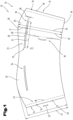
- Two flat blanks 13 are shown as examples of a variety of possible different shapes, wherein the blanks 13 can be wound into a cuff-shaped outer part 12 or into a jacket.
- the flat blank 13 has a substantially circular ring-segment-shaped basic shape, wherein the blank 13 has a first end section 14 and a second end section 15.
- the two end sections 14, 15 are preferably each aligned along an imaginary line to the circle center of the circular ring-segment-shaped basic shape.
- the blank 13 can be wound into a jacket.
- the first end section 14 and the second end section 15 can be coupled to one another in an overlap region 16.
- the end sections 14, 15 can be connected to one another in an overlap region 16 shown in a simplified manner. This can be done by a so-called overlap seam, by means of which the first end section 14 and the second end section 15 adhere to one another, for example by means of an adhesive layer 49.
- the first end section 14 of the blank 13 ends with a first longitudinal edge 17 and the second end section 15 in turn ends with a second longitudinal edge 18.
- the two longitudinal edges 17, 18 can preferably each be aligned along an imaginary line to the circle center of the circular ring segment-shaped basic shape.
- the blank 13 can have a longitudinal edge length 50 in the area of the first end section 14, in particular on the first longitudinal edge 17. When considering the longitudinal edge length 50, any shortening of the actual longitudinal edge length due to rounding or due to a bevel is disregarded here.
- the two longitudinal edges 17, 18 run approximately parallel to one another, with the overlapping area 16 being formed between them with an overlap width when viewed in the circumferential direction of the casing.
- the second end section 15 is folded over the first end section 14 on the outside. It goes without saying that an arrangement is also conceivable in which the first end section 14 is folded over the second end section 15 on the outside.
- the blank 13, or an outer part 12 formed from the blank 13, further comprises a first end face 19 and a second end face 20, wherein the first end face 19 and the second end face 20 are spaced apart from one another, wherein the blank 13 or the outer part 12 has a longitudinal extension 22 in a direction starting from the first end face 19 to the second end face 20.
- the end faces are preferably essentially concentric with respect to the circle center of the circular ring segment-shaped basic shape.
- the two end faces 19, 20, which are spaced apart from one another define an overall height 21 of the jacket when the outer part 12 is in the erected state. In particular when the jacket of the outer part 12 is conical, the overall height 21 corresponds geometrically to a height of the cone when viewed in axial section.
- the longitudinal extent 22 when viewed in axial section is geometrically the length of the jacket line.
- a cut 13 which is essentially in the shape of a segment of a circular ring is wound into a jacket, a conical jacket inevitably results.
- the maximum longitudinal extent 22 in the case of a conical jacket of the outer part 12 is generally greater than the overall height 21 of the jacket.
- the longitudinal axis 8 already described can also define the common longitudinal axis for the outer part 12, in particular when the outer part 12 is in its mounted position on the container 2.
- the overall height 21 of the shell is slightly lower than the container height 9 of the container 2 in the same spatial direction - namely in the direction of the longitudinal axis 8.
- the blank 13, or the outer part 12 formed from it has a receiving area 23 and an area 24, which area 24 is arranged between the receiving area 23 and the second end face 20 when viewed in the longitudinal extension 22.
- the receiving area 23 is designed as a recess, cutout, hole or as an opening in the blank 13 or in the outer part 12.
- the receiving area 23 shown has a first receiving area end 25 and a second receiving area end 26, wherein the first receiving area end 25 faces the first end section 14 of the blank 13 and wherein the second receiving area end 26 faces the second end section 15 of the blank 13, wherein the first receiving area end 25 and the second receiving area end 26 are spaced apart from one another.
- the receiving area 23 therefore has an elongated basic shape.
- the first receiving area end 25 and the second receiving area end 26 can be spaced apart by a length 27, which length 27 can be from 5% to 75% of a receiving area casing circumference of the casing.
- the receiving area 23 can have a circular ring segment-shaped basic shape, which is concentric with the circular ring segment-shaped basic shape of the blank 13.
- the receiving area 23 can further have a first receiving area front side 28, which first receiving area front side 28 faces the first front side 19 and wherein the Receiving area 23 has a second receiving area front side 29, which second receiving area front side 29 faces the second front side 20.
- the first receiving area front side 28 and the second receiving area front side 29 can be spaced apart from one another, wherein the receiving area 23 has a receiving area height 30 in a direction starting from the first receiving area front side 28 to the second receiving area front side 29.
- the receiving area height 30 can be adapted to the type and design of the container 2 to be encased, or the area 40, 41 to be accommodated.
- the second receiving area end face 29 facing the second end face 20 can be spaced apart from the second end face 20 by a first length 31 as viewed in the longitudinal extension 22 of the outer part 12.
- the second receiving area end face 29 facing the second end face 20 can be spaced apart from the first end face 19 by a second length 32 as viewed in the longitudinal extension 22 of the outer part 12.
- the maximum first length 31 and the maximum second length 32 or the sum of the two lengths 31, 32 can define a maximum annular segment height 33, which maximum annular segment height 33 corresponds in particular to a maximum longitudinal extension 22 or a maximum surface line of the conical outer part 12 or a maximum overall height 21.
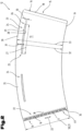
- the first end face 19 and the second end face 20 can be arranged as shown in the Fig.1 It can also be that the first end face 19 is circularly arc-shaped and that the second end face 20 is wave-shaped or sinusoidal. This is shown by way of example in the Fig.2 It goes without saying that these two designs are merely examples of various conceivable shapes. In any case, the first end face 19 and the second end face 20 essentially follow a circular arc shape and are essentially concentric with respect to a circle center of the circular ring segment-shaped basic shape.
- the one in the Fig.1 and 2 The blank 13 shown, or an outer part 12 formed therefrom, has a second receiving area 34 and a second area 35, which second area 35 is arranged between the second receiving area 34 and the second end face 20 when viewed in the longitudinal extension 22 of the outer part 12.
- the receiving area 23 and the second receiving area 34 are of the same dimensions in the examples shown.
- the two areas 24, 35 above the receiving areas 23, 34 are also of the same dimensions.
- the two blanks 13 shown are designed and symmetrical in such a way that the receiving area 23 and the second receiving area 34 are arranged opposite one another in the wound state, i.e. in the casing of the outer part 12.
- a predetermined separation area 36 is also provided.
- the predetermined separation area 36 is a so-called elevation, for example in the sense of WO 2020/245148 A1 of the applicant of the same name.
- the intended separation area 36 extends in a direction starting from the first end face 19 to the receiving area 23, in particular to the first receiving area end face 28.
- a further embodiment is shown, wherein the intended separation region 36 extends in a direction starting from the first end face 19 to the second end face 20.
- the intended separation region 36 is provided in the overlap region 16 of the end sections 14, 15 or the longitudinal edges 17, 18.
- the overlap region 16 can be designed, for example, as a detachable adhesive connection.
- a further exemplary embodiment of a blank 13 or an outer part 12 is shown, wherein the region 24 is formed with a fold line 37.
- the fold line 37 is, when viewed in the wound state, concentric to the jacket of the outer part 12 in relation to a longitudinal axis 8 of the casing of the outer part 12.
- the fold line 37 When viewed in the flat state, the fold line 37 is concentric with respect to the circle center of the circular ring-segment-shaped blank 13 or outer part 12.
- the region 24 between the fold line 37 and the second end face 20 has a fold region 38.
- the fold region 38 has a substantially round basic shape, which can at least approximately correspond to the circular cross-section in the region of the open end of the container to be covered.
- This folding area 38 can be folded inwards, in particular in the wound, jacket-shaped or conical state, in the radial direction towards the longitudinal axis 8 of the jacket of the outer part 12.
- the folding area 38 can have a tab 51, which tab 51 can be coupled, i.e. brought into engagement, with the second receiving area 34 which is opposite in the wound state.
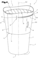
- a combination packaging container 1 is shown as an example for a variety of possible different shapes, wherein the combination packaging container 1 is cup-shaped or bowl-shaped.
- the combination packaging container 1 is in the Fig.3 shown partially cut through the longitudinal axis 8.
- the combination packaging container 1 comprises a cup- or bowl-shaped container 2 with a base 3 and a container casing 4.
- the container 2 also has an open end 5 on its side facing away from the base 3.
- a flange 6 projecting outwards beyond the container casing 4 can be provided in the area of its open end 5.
- the base 3 forms a closed end 7 for the container casing 4.
- the container 2 has an essentially conical or truncated cone-shaped basic shape.
- the combination packaging container 1 When looking at the combination packaging container 1 in the front view shown, the combination packaging container 1 has a total height 10 which extends from the base 3 to the highest area of the second end face 20 of the outer part 12. The total height 10 is thus greater than the container height 9 and also greater than the construction height 21 of the outer part 12.
- the container 2 is preferably formed by a component produced in a deep-drawing process, which can be produced quickly and, above all, in a short cycle time.
- the deep-drawing process is well known and will therefore not be discussed in more detail.
- the deep-drawing process is particularly suitable for producing the container 2 with a sufficient wall thickness from a layer of a deformable material using a deep-drawing tool, which ensures tightness during storage, use and disposal.
- This manufacturing process enables the inner container 2 to have relatively thin walls.
- the container 2 can also be formed using other manufacturing processes, such as an injection molding process.
- a longitudinal axis 8 extends in the axial direction between the open end 5 and the end 7 closed with the base 3, which can also represent a central axis if the design is symmetrical.
- a closure element 39 for example a sealing plate, or to connect it to it.
- the flange 6 forms a sealing flange.
- the container 2 In the axial direction and thus in the direction of the longitudinal axis 8, the container 2 has a container height 9 between its open end 5, in particular the flange 6, and the bottom 3, whereby, depending on the cross-sectional dimensions, the receiving volume of the container 2 is determined.
- the container height 9 in conjunction with the cross-sectional dimensions thus defines a receiving space for the container 2.
- the container shell 4 is understood to be that section of the container 2 which extends between the open end 5, in particular the flange 6, and the base 3 in a predominantly axial direction.
- the container 2 with its container shell 4 is preferably designed in such a way that it tapers conically from the open end 5 to the base 3, i.e. is essentially frustoconical.
- the longitudinal axis 8 corresponds to the cone axis 42.
- the combination packaging container 1 further comprises an outer part 12 which is designed in the shape of a sleeve or jacket and surrounds the container 2 in the region of its container jacket 4 at least in sections or regions.
- the sleeve-shaped outer part 12 is preferably made of a cellulose material, such as a cardboard material, with sufficient strength in relation to the absorption and transmission of in particular axially acting pressure forces and is wound from a flat blank 13 to form a jacket.
- the blank 13 is usually printed in its undeformed flat position and optionally provided with an additional coating.
- a cellulose material is usually used as the material for the blank 13, although this can also be cardboard or strong paper produced using a recycling process. If a layer or ply of the outer part 12 is made of a recycled material, an additional layer made of a higher quality paper can be arranged on or connected to at least one of the surfaces. This additional layer is used to ensure perfect printing for the production of decorations, labels and product information.
- the sleeve-like or jacket-like outer part 12 leads to an additional reinforcement or stiffening effect of the container 2 and thus of the entire combination packaging container 1. This provides, on the one hand, high strength and good thermal insulation and, on the other hand, optimal light protection for the contents of the packaging container.
- the cardboard is additionally coated or sealed with a water-repellent material in the area of the cut edges. This is particularly advantageous if the combination packaging container 1 is subject to increased are exposed to moisture. Coating the cardboard used for the outer part 12 with a water-repellent layer prevents the cardboard from swelling in a humid environment and ultimately becoming detached from the container casing 4 of the combination packaging container 1.
- the container 2 can preferably be a reusable container, which in particular is or comprises a plastic material or a recycled plastic material.
- the container 2 has an alignment means 52 in the region of its bottom 3, in particular as in the Fig.3 schematically shown has a groove or an elevation which is designed for fixing and/or positioning the container 2.
- the casing of the outer part 12 has a receiving area 23 and an area 24, which area 24 is arranged between the receiving area 23 and the second end face 20 when viewed in the longitudinal extension 22.
- the outer part 12 is wound around the container 2 so that an area 40 of the open end 5 and an area 41 of the closure element 39 of the container 2 are received in the receiving area 23 of the casing of the outer part 12.
- the areas 40, 41 and a part of the flange 6 or a part of a collar 45 protrude beyond the casing of the outer part 12 in an imaginary, shortest straight connecting line between the longitudinal axis 8 or the cone axis 42 and the areas 40, 41 when viewing the combination packaging container 1 in axial section.
- the region 24 of the outer part 12, viewed in the longitudinal extension 22, can extend beyond the open end 5 of the container 2, i.e. projects beyond the open end 5 and the closure element 39.
- the closure element 39 is designed or arranged in such a way that removal is only possible after removal of the outer part 12 from the container 2. This is shown in the embodiment shown in the Fig.3 realized in that the closure element 39 is partially received in the receiving areas 23, 34.
- closure element 39 is connected to the casing of the outer part 12, and that the closure element 39 is so is designed such that removal is possible at the same time as removal of the outer part 12 from the container 2.
- the closure element 39 can be designed as a sealing plate, which sealing plate can be glued or otherwise connected to the casing of the outer part 12, so that the sealing plate is also removed when the outer part 12 is separated.
- the jacket of the outer part 12 can extend over a part of the container jacket 4.
- the jacket of the outer part 12 extends over a part of the container jacket 4, which corresponds to a quarter to two thirds of the container jacket 4.
- Outer parts 12 are shown with different high surface lines or different maximum longitudinal extensions 22. Consequently, the parts of the container 2 visible to an observer are of different sizes.
- the container shell 4 of the container 2 and the shell of the outer part 12 can be as shown in the Fig. 3 to 6 shown be essentially frustoconical and arranged around a common cone axis 42.
- a first angle 43 between the container shell 4 of the container 2 and the cone axis 42 is larger than a second angle 44 between the shell of the outer part 12 and the cone axis 42.
- Fig.3 shown partial axial section that the open end 5 and the closure element 39 have a collar 45 projecting over the container shell 4 of the container 2 in the radial direction to the cone axis 42, wherein a third angle 48 is formed between the cone axis 42 and an imaginary cutting line 46, which imaginary cutting line 46 extends from an outermost point of the collar 45 to the cone axis 42 and intersects the first end face 19, wherein the third angle 48 is larger than the second angle 44.
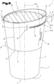
- Fig. 4 to 6 each show a three-dimensional view of an embodiment of a combination packaging container 1, whereby the examples are to be understood as representative of a large number of conceivable shapes. Reference is made to the above In order to avoid unnecessary repetition, special features of the variants shown are discussed below.
- the Indian Fig.4 The combination packaging container 1 shown is covered with an outer part 12 which has a wave-shaped second end face 20.
- the container 2 is closed with a closure element 39 designed as a sealing plate or film, and a collar 45 or a flange 6 in the area of the open end 5 protrude in the radial direction to the longitudinal axis 8 or to the cone axis 42 from the receiving area 23 of the outer part 12.
- a predetermined separation region 36 is provided below the receiving region 23, which extends along the surface line in the longitudinal extension 22 from the first end face 19 to the first receiving region end face 28.
- the Indian Fig.5 The combination packaging container 1 shown is also covered with an outer part 12, whereby the outer part 12 is smaller than the outer part 12 shown in the Fig.4 shown example is longer, and thus encases or covers a larger part of the container 2.
- the second end face 20 is also wave-shaped, but has a smaller Fig.4 two instead of three wave crests or elevations.
- the Fig.5 It can also be seen that a second receiving area 34 is provided, from which the collar 45 or the flange 6 of the container 2 protrudes.
- FIG.6 another combination packaging container 1 is shown, which is also covered with an outer part 12.
- the second end face 20 of the outer part 12 is also wave-shaped here, but only has one wave crest or an elevation.
- the area 24 above the receiving area 23, i.e. the first length 31, is larger than the second area 35 above the second receiving area 34, or the first length 31 formed above it.
- the container 2 can be fixed and/or positioned in the region of the bottom 3 of the container 2 by coupling a coupling element to an alignment means 52, in particular to a groove or to an elevation, before being wrapped with the outer part 12 or before the outer part 12 is pushed on axially.
Landscapes
- Engineering & Computer Science (AREA)
- Mechanical Engineering (AREA)
- Ceramic Engineering (AREA)
- Packages (AREA)
Applications Claiming Priority (1)
| Application Number | Priority Date | Filing Date | Title |
|---|---|---|---|
| ATA50782/2022A AT525891B1 (de) | 2022-10-10 | 2022-10-10 | Außenteil und damit ausgestatteter Kombi-Verpackungsbehälter, Verfahren zur Herstellung und |
Publications (1)
| Publication Number | Publication Date |
|---|---|
| EP4353613A1 true EP4353613A1 (fr) | 2024-04-17 |
Family
ID=87973337
Family Applications (1)
| Application Number | Title | Priority Date | Filing Date |
|---|---|---|---|
| EP23202602.1A Pending EP4353613A1 (fr) | 2022-10-10 | 2023-10-10 | Pièce extérieure et récipient d'emballage combiné équipé de celle-ci, procédé de fabrication et procédé d'ouverture |
Country Status (4)
| Country | Link |
|---|---|
| US (1) | US20240116687A1 (fr) |
| EP (1) | EP4353613A1 (fr) |
| AT (1) | AT525891B1 (fr) |
| CA (1) | CA3215917A1 (fr) |
Citations (4)
| Publication number | Priority date | Publication date | Assignee | Title |
|---|---|---|---|---|
| JPH0637142U (ja) * | 1992-10-19 | 1994-05-17 | 雪印乳業株式会社 | 容器の保冷保温具 |
| DE29611301U1 (de) * | 1995-08-16 | 1996-08-29 | Wilke Werner Heinz | Zweiteiliger Verpackungsbehälter und Kartonzuschnitt |
| DE29708178U1 (de) * | 1997-05-06 | 1998-09-17 | Gizeh Verpackungen Gmbh & Co K | Becher |
| WO2020245148A1 (fr) | 2019-06-07 | 2020-12-10 | Greiner Packaging Ag | Pièce externe en forme de manchette ainsi que conteneur d'emballage combiné muni de celle-ci et procédé de séparation du conteneur d'emballage combiné |
Family Cites Families (2)
| Publication number | Priority date | Publication date | Assignee | Title |
|---|---|---|---|---|
| DE202005014177U1 (de) * | 2005-09-08 | 2005-11-17 | Seda S.P.A., Arzano | Doppelwandiger Becher |
| US20080302800A1 (en) * | 2007-06-05 | 2008-12-11 | Shin-Jai Chou | Plastic portable heat insulation cup |
-
2022
- 2022-10-10 AT ATA50782/2022A patent/AT525891B1/de active
-
2023
- 2023-10-06 US US18/377,412 patent/US20240116687A1/en active Pending
- 2023-10-06 CA CA3215917A patent/CA3215917A1/fr active Pending
- 2023-10-10 EP EP23202602.1A patent/EP4353613A1/fr active Pending
Patent Citations (4)
| Publication number | Priority date | Publication date | Assignee | Title |
|---|---|---|---|---|
| JPH0637142U (ja) * | 1992-10-19 | 1994-05-17 | 雪印乳業株式会社 | 容器の保冷保温具 |
| DE29611301U1 (de) * | 1995-08-16 | 1996-08-29 | Wilke Werner Heinz | Zweiteiliger Verpackungsbehälter und Kartonzuschnitt |
| DE29708178U1 (de) * | 1997-05-06 | 1998-09-17 | Gizeh Verpackungen Gmbh & Co K | Becher |
| WO2020245148A1 (fr) | 2019-06-07 | 2020-12-10 | Greiner Packaging Ag | Pièce externe en forme de manchette ainsi que conteneur d'emballage combiné muni de celle-ci et procédé de séparation du conteneur d'emballage combiné |
Also Published As
| Publication number | Publication date |
|---|---|
| CA3215917A1 (fr) | 2024-04-10 |
| AT525891A4 (de) | 2023-09-15 |
| AT525891B1 (de) | 2023-09-15 |
| US20240116687A1 (en) | 2024-04-11 |
Similar Documents
| Publication | Publication Date | Title |
|---|---|---|
| EP1976764B1 (fr) | Systeme d'ouverture refermable realise a partir d'un produit semi-fini et procede pour son montage | |
| EP3980340B1 (fr) | Pièce externe en forme de manchette ainsi que conteneur d'emballage combiné muni de celle-ci et procédé de séparation du conteneur d'emballage combiné | |
| EP2125542B1 (fr) | Dispositif de fermeture en plastique pourvu d'un tube coupant | |
| EP2566768B1 (fr) | Emballage avec fermeture filetée | |
| EP0916587A1 (fr) | Fermeture inviolable | |
| EP1876106A1 (fr) | Combinaison de récipients à partir d'au moins deux parties de récipients | |
| EP2334567B1 (fr) | Poignée de manutention pour conteneur | |
| EP3829992B1 (fr) | Emballage de tube | |
| EP4353613A1 (fr) | Pièce extérieure et récipient d'emballage combiné équipé de celle-ci, procédé de fabrication et procédé d'ouverture | |
| WO2002036451A1 (fr) | Capuchon filete pourvu d'une bande de garantie | |
| EP2838807B1 (fr) | Récipient d'emballage combiné | |
| EP3822189A1 (fr) | Emballage, unité d'emballage pour un emballage et procédé de fabrication d'un emballage | |
| WO2019197214A1 (fr) | Bouchon à vis davantage inviolable | |
| EP3107817B1 (fr) | Couvercle de fermeture muni d'une garantie d'inviolabilité et unité d'emballage munie dudit couvercle | |
| AT524826B1 (de) | Manschettenförmiges Außenteil, damit ausgestatteter Kombi-Verpackungsbehälter und Verfahren zum Trennen des Kombi-Verpackungsbehälters | |
| WO2018162661A1 (fr) | Dispositif de fermeture de récipient et récipient comportant ce tel dispositif de fermeture de récipient | |
| AT506749A1 (de) | Verfahren zur herstellung eines kombi-verpackungsbehälters | |
| DE4438076A1 (de) | Dose | |
| DE102021000404A1 (de) | Originalitätsverschlusskappe aus Kunststoff | |
| DE69907140T2 (de) | Faltschachtel mit schüttvorrichtung und verfahren zu ihrer herstellung | |
| EP4353620A2 (fr) | Récipient réutilisable en matière plastique et procédé de recyclage | |
| WO2016128521A1 (fr) | Procédé de fabrication d'un récipient en matière plastique, récipient et élément à étiquettes | |
| DE10335937A1 (de) | Verschließbarer Behälter | |
| WO2010063417A2 (fr) | Procédé de fabrication d'un récipient d'emballage combiné | |
| EP1790582A1 (fr) | Fermeture inviolable |
Legal Events
| Date | Code | Title | Description |
|---|---|---|---|
| PUAI | Public reference made under article 153(3) epc to a published international application that has entered the european phase |
Free format text: ORIGINAL CODE: 0009012 |
|
| STAA | Information on the status of an ep patent application or granted ep patent |
Free format text: STATUS: THE APPLICATION HAS BEEN PUBLISHED |
|
| AK | Designated contracting states |
Kind code of ref document: A1 Designated state(s): AL AT BE BG CH CY CZ DE DK EE ES FI FR GB GR HR HU IE IS IT LI LT LU LV MC ME MK MT NL NO PL PT RO RS SE SI SK SM TR |