EP4350098A1 - Gebäude - Google Patents
Gebäude Download PDFInfo
- Publication number
- EP4350098A1 EP4350098A1 EP22815771.5A EP22815771A EP4350098A1 EP 4350098 A1 EP4350098 A1 EP 4350098A1 EP 22815771 A EP22815771 A EP 22815771A EP 4350098 A1 EP4350098 A1 EP 4350098A1
- Authority
- EP
- European Patent Office
- Prior art keywords
- wall
- panel
- communication path
- atrium
- building
- Prior art date
- Legal status (The legal status is an assumption and is not a legal conclusion. Google has not performed a legal analysis and makes no representation as to the accuracy of the status listed.)
- Withdrawn
Links
- 210000002837 heart atrium Anatomy 0.000 claims description 65
- 238000004891 communication Methods 0.000 claims description 60
- 238000004378 air conditioning Methods 0.000 claims description 39
- 238000001816 cooling Methods 0.000 claims description 19
- 239000005357 flat glass Substances 0.000 claims description 16
- 230000005540 biological transmission Effects 0.000 claims description 12
- 238000009434 installation Methods 0.000 claims description 12
- 238000009413 insulation Methods 0.000 claims description 10
- 238000001179 sorption measurement Methods 0.000 claims description 10
- 230000001143 conditioned effect Effects 0.000 claims description 9
- 238000010438 heat treatment Methods 0.000 claims description 9
- 239000000463 material Substances 0.000 claims description 8
- 230000000149 penetrating effect Effects 0.000 claims description 8
- 238000003860 storage Methods 0.000 description 7
- 238000009423 ventilation Methods 0.000 description 7
- 239000012530 fluid Substances 0.000 description 4
- 238000000034 method Methods 0.000 description 4
- 238000010521 absorption reaction Methods 0.000 description 3
- 230000000694 effects Effects 0.000 description 2
- 238000005057 refrigeration Methods 0.000 description 2
- 101100021975 Arabidopsis thaliana LTL1 gene Proteins 0.000 description 1
- 239000006096 absorbing agent Substances 0.000 description 1
- 230000015572 biosynthetic process Effects 0.000 description 1
- 230000000903 blocking effect Effects 0.000 description 1
- 230000005494 condensation Effects 0.000 description 1
- 238000009833 condensation Methods 0.000 description 1
- 238000005520 cutting process Methods 0.000 description 1
- 230000006866 deterioration Effects 0.000 description 1
- 230000002542 deteriorative effect Effects 0.000 description 1
- 238000001704 evaporation Methods 0.000 description 1
- 230000008020 evaporation Effects 0.000 description 1
- 239000007788 liquid Substances 0.000 description 1
- 238000004519 manufacturing process Methods 0.000 description 1
- 238000012986 modification Methods 0.000 description 1
- 230000004048 modification Effects 0.000 description 1
- 239000003507 refrigerant Substances 0.000 description 1
- 238000003892 spreading Methods 0.000 description 1
Images


Classifications
-
- E—FIXED CONSTRUCTIONS
- E04—BUILDING
- E04C—STRUCTURAL ELEMENTS; BUILDING MATERIALS
- E04C2/00—Building elements of relatively thin form for the construction of parts of buildings, e.g. sheet materials, slabs, or panels
- E04C2/44—Building elements of relatively thin form for the construction of parts of buildings, e.g. sheet materials, slabs, or panels characterised by the purpose
- E04C2/52—Building elements of relatively thin form for the construction of parts of buildings, e.g. sheet materials, slabs, or panels characterised by the purpose with special adaptations for auxiliary purposes, e.g. serving for locating conduits
- E04C2/521—Building elements of relatively thin form for the construction of parts of buildings, e.g. sheet materials, slabs, or panels characterised by the purpose with special adaptations for auxiliary purposes, e.g. serving for locating conduits serving for locating conduits; for ventilating, heating or cooling
- E04C2/525—Building elements of relatively thin form for the construction of parts of buildings, e.g. sheet materials, slabs, or panels characterised by the purpose with special adaptations for auxiliary purposes, e.g. serving for locating conduits serving for locating conduits; for ventilating, heating or cooling for heating or cooling
-
- E—FIXED CONSTRUCTIONS
- E04—BUILDING
- E04B—GENERAL BUILDING CONSTRUCTIONS; WALLS, e.g. PARTITIONS; ROOFS; FLOORS; CEILINGS; INSULATION OR OTHER PROTECTION OF BUILDINGS
- E04B1/00—Constructions in general; Structures which are not restricted either to walls, e.g. partitions, or floors or ceilings or roofs
- E04B1/348—Structures composed of units comprising at least considerable parts of two sides of a room, e.g. box-like or cell-like units closed or in skeleton form
- E04B1/34815—Elements not integrated in a skeleton
-
- E—FIXED CONSTRUCTIONS
- E04—BUILDING
- E04B—GENERAL BUILDING CONSTRUCTIONS; WALLS, e.g. PARTITIONS; ROOFS; FLOORS; CEILINGS; INSULATION OR OTHER PROTECTION OF BUILDINGS
- E04B1/00—Constructions in general; Structures which are not restricted either to walls, e.g. partitions, or floors or ceilings or roofs
- E04B1/62—Insulation or other protection; Elements or use of specified material therefor
- E04B1/74—Heat, sound or noise insulation, absorption, or reflection; Other building methods affording favourable thermal or acoustical conditions, e.g. accumulating of heat within walls
- E04B1/76—Heat, sound or noise insulation, absorption, or reflection; Other building methods affording favourable thermal or acoustical conditions, e.g. accumulating of heat within walls specifically with respect to heat only
- E04B1/78—Heat insulating elements
- E04B1/80—Heat insulating elements slab-shaped
- E04B1/803—Heat insulating elements slab-shaped with vacuum spaces included in the slab
-
- E—FIXED CONSTRUCTIONS
- E04—BUILDING
- E04C—STRUCTURAL ELEMENTS; BUILDING MATERIALS
- E04C2/00—Building elements of relatively thin form for the construction of parts of buildings, e.g. sheet materials, slabs, or panels
- E04C2/44—Building elements of relatively thin form for the construction of parts of buildings, e.g. sheet materials, slabs, or panels characterised by the purpose
- E04C2/46—Building elements of relatively thin form for the construction of parts of buildings, e.g. sheet materials, slabs, or panels characterised by the purpose specially adapted for making walls
-
- E—FIXED CONSTRUCTIONS
- E04—BUILDING
- E04C—STRUCTURAL ELEMENTS; BUILDING MATERIALS
- E04C2/00—Building elements of relatively thin form for the construction of parts of buildings, e.g. sheet materials, slabs, or panels
- E04C2/44—Building elements of relatively thin form for the construction of parts of buildings, e.g. sheet materials, slabs, or panels characterised by the purpose
- E04C2/52—Building elements of relatively thin form for the construction of parts of buildings, e.g. sheet materials, slabs, or panels characterised by the purpose with special adaptations for auxiliary purposes, e.g. serving for locating conduits
- E04C2/521—Building elements of relatively thin form for the construction of parts of buildings, e.g. sheet materials, slabs, or panels characterised by the purpose with special adaptations for auxiliary purposes, e.g. serving for locating conduits serving for locating conduits; for ventilating, heating or cooling
- E04C2/523—Building elements of relatively thin form for the construction of parts of buildings, e.g. sheet materials, slabs, or panels characterised by the purpose with special adaptations for auxiliary purposes, e.g. serving for locating conduits serving for locating conduits; for ventilating, heating or cooling for ventilating
Definitions
- the present disclosure relates to a building.
- vacuum insulation panels are often used on the outer walls of a building to keep the interior of the building comfortable.
- air conditioning panels have also been suggested, in which the panels themselves provide the air conditioning function, such as heat pipe panels that allow heat transmission from one surface to the other surface while blocking the heat transmission from the other surface to the one surface, and cooling panels in which an absorption or adsorption refrigerator is formed into a panel shape (for example, see PTLs 1 and 2).
- the vacuum insulation panels and the air conditioning panels have a vacuum portion inside the panels, the panels cannot be cut when used as the outer walls of a building.
- the walls are often not in a size that is an integer multiple of the standard size, resulting in odd portions that cannot be filled with panels of the standard size. Furthermore, when the positions of the toilet window, the bathroom window, and the kitchen window are determined, many odd portions are generated around the windows. As a result, the area occupied by standard-sized panels on a wall of a building is reduced, resulting in a decrease in the comfort of the building.
- the present disclosure has been made to solve the problems described above, and accordingly, an object is to provide a building that can provide improved comfort.
- a building according to the present disclosure includes a wall part including at least one of a first wall and a second wall, in which
- a building that can provide further improved comfort can be provided.
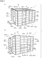
- FIG. 1 are perspective views of an example of a building according to an embodiment of the present disclosure, in which (a) shows a perspective view of one surface side, and (b) shows a perspective view of the other surface side.
- a building 1 according to the example shown in FIG. 1 includes a wall part 10 and a ceiling part 20.
- the wall part 10 is configured to include a panel member P and a window portion W.
- the window portion W may be of a slide opening/closing type, a depth opening/closing type, or a fixed type that is fixed and cannot be opened or closed.
- the panel member P includes a single plate member that serves as both an outer wall and an interior material, and has a uniform standard size with a predetermined width and a predetermined height.
- the predetermined width is a width of 90 cm or more and less than 5 m, and more preferably, a width of 182 cm.
- the predetermined height is a height of 45 cm or more and less than 2 m, and more preferably, a height of 91 cm.
- This panel member P includes at least one kind of a vacuum insulation panel, a heat pipe panel, and a cooling panel.
- the vacuum insulation panel is a panel having an evacuated vacuum layer therein.
- the heat pipe panel is a panel that allows heat transmission from one surface side to the other surface side and prevents the heat transmission from the other surface side to the one surface side.
- This heat pipe is a panel that has a working fluid therein and allows heat transmission from one surface side to the other surface side as the working fluid evaporates on one surface side and takes heat, and the vapor generated by the evaporation reaches the other surface side and dissipates the heat of condensation from the other surface side.
- This heat pipe panel has an inclined structure therein and has a structure in which the working fluid condensed on the other surface side returns to the one surface side by its own weight.
- the heat pipe panel has a vacuum or the like therein and prevents the heat transmission from the other surface side to the one surface side.
- the cooling panel is a panel that exhibits a refrigerating function by absorption or adsorption, and includes, in a plate shape, a regenerator, a condenser, an evaporator, and an absorber which form an absorption refrigeration cycle, or an adsorber, a condenser, and an evaporator which form an adsorption refrigeration cycle.
- the vacuum insulation panel has the vacuum layer therein
- the heat pipe panel has the vacuum layer and the working fluid therein
- the cooling panel has the vacuum portion, adsorption liquid, and refrigerant in the evaporator, such that the panels cannot be cut. Therefore, in the building 1 according to the present embodiment, without cutting, a large number of panel members P of the standard size are used.
- the wall part 10 is formed by connecting a plurality of standard-sized panel members P in the plane direction, that is, by connecting the long sides or the short sides to form an upright surface, for example.
- the wall part 10 includes a non-connecting portion formed on a part of the upright surface where the panel member P is not arranged, and the non-connecting portion serves as the window portion W. That is, in a general building, the layouts of a living room, a toilet, a bathroom, and the like are first determined, and then windows corresponding to each room such as the living room are determined, and the non-window portions are filled with walls.
- a plurality of panel members P are connected to form a wall, while there is provided a portion to be used as a window at a part where the panel members P are not connected, so as to utilize a large number of panel members P, that is, to increase the utilization rate of the panel members P.
- the wall part 10 when each side of the wall part 10 is N times the predetermined width, the wall part 10 includes (N- ⁇ ) panel members P arranged side by side and a window portion W corresponding to the area of the ⁇ panel members P.
- Each surface of the wall part 10 is an example of the first wall.
- N is an integer of 2 or more, and is 3 or 5 in the example shown in FIG. 1 .
- ⁇ is an integer equal to or greater than 0 and less than N, and is 1 or 2 in the example shown in FIG. 1(a) and 1 in the example shown in FIG. 1(b) .
- ⁇ is "0" at a certain height position H1
- ⁇ is "2" at another height position H2.
- the entrance E is formed in the same manner as the window portion W in the example shown in FIG. 1(b) . That is, at a height position H3 where the entrance E is formed, the wall part 10 includes (N- ⁇ ) panel members P arranged side by side and the entrance E corresponding to an area of ⁇ panel members. It is to be noted that, while there is only the entrance E formed at the height position H3, the window portion W may also be formed.
- FIG. 2 is a plan view of another example of the wall part 10.
- the wall part 10 is not necessarily be N times the predetermined width and may have a remainder that is smaller than the predetermined width. Therefore, when there is the remainder, the wall part 10 as an example of a second wall is formed as follows.
- the wall part 10 When there is a remainder in the width of the wall part 10 with respect to M times the predetermined width, the wall part 10 includes (M- ⁇ ) panel members P arranged side by side in the width direction and a window portion W corresponding to the sum of an area of ⁇ sheets of panel members P and an area corresponding to the remainder.
- M is an integer of 2 or more, and is 3 in the example shown in FIG. 2 .
- ⁇ is an integer of 0 or more and a number less than M. Specifically, at a certain height position H4, ⁇ is "0" and the window portion W corresponding to the remaining area is formed. At another height position H5, ⁇ is " 1", and the window portion W corresponding to an area of one sheet plus the remainder is formed.
- the utilization rate of the panel members P in the width direction is increased.
- a specific wall 10a of the wall part 10 has a height that is an integer multiple of the predetermined height of the standard size, and 6 times in the example shown in FIG. 1(a) , and has a stacked portion, that is, a portion in which the corresponding integer number of panel members P are stacked.
- a connection wall 10c connecting the specific wall 10a and the opposing wall 10b includes a plurality of panel members P, or particularly, the number of panel members P equal to or less than the integer multiple, and a triangular portion T1 or trapezoidal portions T2 used at an upper end portion.
- the triangular portion T1 and one of the trapezoidal portions T2 is a plate material for building, and the remaining one of the trapezoidal portions T2 is the window portion W.
- the trapezoidal portion T2 is the window portion W, but embodiments are not limited thereto, and the triangular portion T1 may be the window portion W.
- FIG. 3 is a front view of an example of the window portion W according to the present embodiment.
- the window portion W is not entirely configured as a window glass installation part WGP for installing a window glass WG, and preferably includes a through plate installation part THP for installing a plate material B (hatched portion in FIG. 3 ) having a through hole TH penetrating indoors and outdoors.
- the panel member P cannot be cut and also cannot have the through hole TH formed therein.
- the building 1 requires outer wall penetrating elements such as ventilation port, exhaust port, introduction of power lines and telephone lines, and antenna wiring. Therefore, these outer wall penetrating elements are formed in the window portion W, and it is not necessary to form the through hole TH in the panel member P.
- FIG. 4 is a perspective view of the structure when the wall part 10 is removed from the building 1 according to the present embodiment.
- FIG. 5 is a plan view of the first floor of the building 1 shown in FIG. 4
- FIG. 6 is a plan view of the second floor of the building 1 shown in FIG. 4 .
- FIG. 7 is a partially enlarged perspective view of the first floor shown in FIG. 4
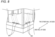
- FIG. 8 is another enlarged perspective view of the first floor shown in FIG. 4 .
- the building 1 is preferably configured as described in 1) to 8) below.
- a unit including at least two or more of the storage room, the toilet TO, the kitchen K, and the bathroom BA integrated therein is manufactured in advance in a factory.
- the foundation L is formed and then the frame, floor surface, and ceiling 20 are formed, and the unit is arranged at a predetermined position in the indoor space.
- a large number of panel members P are connected and stacked. Then, non-connected gaps are formed in certain areas. After that, a window glass WG, a door, and the like are installed in the gaps to form the window portion Wand the entrance E. It is to be noted that the order of operations is not limited to that described above, and the panel members P may be installed after the window glass WG, doors, and the like are installed as usual.
- the wall part 10 is formed so as to be filled with the standard size panel members P without requiring the standard size panel members P to be cut, and parts of the wall part 10 are formed as the window portion W or the like.
- the wall part 10 includes (N- ⁇ ) panel members P arranged side by side at specific height positions H1 and H2, and window portions W corresponding to the area of ⁇ panels.
- the wall part 10 when the width of the wall part 10 has a remainder with respect to M times the predetermined width, the wall part 10 includes (M - ⁇ ) panel members P arranged side by side in the width direction, and window portions W corresponding to the area of ( ⁇ + remainder) at specific height positions H4 and H5.
- the entrance E is also made in the same manner as the window portion W described above.
- the wall part 10 in the width direction except for the necessary parts of the window portion Wand the entrance E, are filled with the panel members P of the standard size, and the utilization rate of the panel members P is increased.
- connection wall 10c shown in FIG. 1 a plurality of panel members P are used, and the upper end includes the triangular portion T1 or the trapezoidal portion T2, and the triangular portion T1 or the trapezoidal portion T2 is a window portion W. Therefore, by using the odd portion of the upper end as a light-receiving portion, it is possible to contribute to reducing the window portion W below the upper end, and the utilization rate of the panel member P is increased.
- the window portion W includes the through plate installation part THP for installing the plate material B having the through hole TH. Therefore, it is not necessary to form the through hole TH in the panel member P in order to provide the outer wall penetrating elements, such as a ventilation port, an exhaust port, an intake of power line, telephone line, and the like, the antenna wiring, and the like, and a situation in which the panel member P loses its function is prevented.
- the outer wall penetrating elements such as a ventilation port, an exhaust port, an intake of power line, telephone line, and the like, the antenna wiring, and the like
- the panel member P is the air conditioning panel P1
- the storage room, the toilet TO, and the bathroom BA are installed in the central portion away from the wall part 10. Therefore, the cooled or heated air by the air conditioning panel P1 is prevented from being confined in relatively small rooms such as the storage room, the toilet TO, the kitchen K, and the bathroom BA, thereby contributing to the improvement of comfort.
- At least one of the first atrium A1, the second atrium A2, and the upper communication path UL1 is air conditioned by the air conditioning panel P1, and the circulation structure of the air is formed by the first atrium A1, the second atrium A2, the upper communication path UL1, and the underfloor communication path UL2.
- the cooled or heated air circulates inside the building 1. Therefore, it contributes to the improvement of comfort.
- the air conditioning panel P1 is provided with the fan F that assists the cooling and heating function so that the downward flow is generated when cooling the atria A1 and A2, and the upward flow is generated when heating the same. Therefore, it is possible to further facilitate spreading the cooled or heated air throughout the building 1, contributing to an improvement in comfort.
- the air conditioner AR is provided in the underfloor communication path UL2, not only the comfort improved by the air conditioner AR, but also the deterioration of the appearance due to the installation of the outdoor unit and the piping is prevented.
- the building 1 has the skip floor and the space S is defined between the one step lower floor surface LF and the normal-height floor surface NF, the circulation of the air can be further facilitated.
- the building 1 when the wall part 10 is N times the predetermined width of the standard size, (N- ⁇ ) panel members P are arranged side by side in the width direction to form the window portion W corresponding to the area of ⁇ sheets.
- (M- ⁇ ) panel members P when the wall part 10 has a remainder with respect to M times the predetermined width of the standard size, (M- ⁇ ) panel members P are arranged side by side in the width direction to form the window portion W corresponding to the area of ⁇ sheets plus the remainder.
- the specific wall 10a has the integer number of panel members P stacked, it is possible to increase the utilization rate of the panel members for the specific wall 10a.
- the connection wall 10c has a plurality of panel members P and the window portion W having a triangular or trapezoidal shape at the upper end, by using the odd portion of the upper end as a light-receiving portion, it is possible to contribute to reducing the window portion W below the upper end, and the utilization rate of the panel members P is increased.
- the window portion W has the window glass installation part WGP and the through plate installation part THP for installing the plate material B having the through hole TH penetrating indoors and outdoors. Therefore, it is not necessary to form the through hole TH in the panel member P for the outer wall penetrating element such as a ventilation port, an exhaust port, a power line, a telephone line, and the like, or an antenna wiring, and it is possible to prevent the panel member P from losing its function due to the formation of the through holes and deteriorating comfort.
- the outer wall penetrating element such as a ventilation port, an exhaust port, a power line, a telephone line, and the like, or an antenna wiring
- the panel members P are provided on the wall part 10, and at least one of the storage room, the toilet TO, the bathroom BA, and the kitchen K are installed in the central portion away from the wall part 10. Therefore, the air that is conditioned by the building 1 is less likely to be confined in the narrow spaces such as the storage room, the toilet TO, the bathroom BA, and the kitchen K, and it is possible to contribute to the improvement of comfort.
- the building 1 includes a plurality of atria A1 and A2 facing the one wall W1 and the other wall W2, respectively, the upper communication path UL1 communicating between the uppermost floors of the atria A1 and A2, and the lower communication path UL2 communicating between the lower floors of the atria A1 and A2.
- at least one of the atria A1 and A2 and the upper communication path UL1 is air conditioned by the air conditioning panel P 1. Therefore, the cooled or heated air by the air conditioning panel P1 circulates through the atria A1 and A2, the upper communication path UL1, and the lower communication path UL2. As a result, it is easier for the cooled or heated air to spread throughout the building 1, thereby improving comfort.
- the building 1 includes the fan F that assists the cooling and heating function.
- the fan F generates a downward flow in the atria A1 and A2 when the air conditioning panel P1 for air conditioning the atria A1 and A2 provides the cooling function, and generates an upward flow in the atria A1 and A2 when the air conditioning panel P1 for air conditioning the atria A1 and A2 provides the heating function. Therefore, the indoor air is appropriately circulated according to the cooling and heating, so that the cooled or heated air is more easily distributed inside the building 1, and the comfort can be further improved.
- the building 1 further includes the air conditioner AR installed in the underfloor communication path UL2, in which the lower communication path UL2 is the underfloor communication path UL2 that communicates between lower floors through the underfloor. Therefore, unlike the air conditioner AR installed on the upper floor, the piping for connecting the air conditioner AR on the upper floor to the outdoor unit does not necessarily run along the wall surface, and it is also possible to connect the underfloor air conditioner AR to the outdoor unit with a short pipe, thus contributing to improving the appearance of the building 1.
- the wall parts 10a to 10c are used in the wall parts 10a to 10c on all surfaces of the building 1.
- the wall parts 10a to 10c include (N- ⁇ ) panel members P arranged side by side in the width direction, and window portions W corresponding to the area of ⁇ pieces.
- the wall parts 10a to 10c have a remainder of less than the predetermined width with respect to M times the predetermined width thereof, the wall parts 10a to 10c have (M- ⁇ ) panel members arranged side by side in the width direction, and a window portion W corresponding to the area of ⁇ sheets plus the remainder.
- the wall parts 10a to 10c are not limited to being configured as described above on all surfaces, and may be configured as described above on at least one surface, for example. This is to increase the utilization rate of the panel members P for the corresponding surface.
- a building that can provide further improved comfort can be provided.
- the present disclosure with the effect described above is useful for buildings.
Landscapes
- Engineering & Computer Science (AREA)
- Architecture (AREA)
- Civil Engineering (AREA)
- Structural Engineering (AREA)
- Physics & Mathematics (AREA)
- Mechanical Engineering (AREA)
- Electromagnetism (AREA)
- Sustainable Development (AREA)
- Life Sciences & Earth Sciences (AREA)
- Acoustics & Sound (AREA)
- Building Environments (AREA)
- Load-Bearing And Curtain Walls (AREA)
- Vending Machines For Individual Products (AREA)
- Buildings Adapted To Withstand Abnormal External Influences (AREA)
Applications Claiming Priority (2)
| Application Number | Priority Date | Filing Date | Title |
|---|---|---|---|
| JP2021092743A JP2022185220A (ja) | 2021-06-02 | 2021-06-02 | 建築物 |
| PCT/JP2022/019186 WO2022255016A1 (ja) | 2021-06-02 | 2022-04-27 | 建築物 |
Publications (2)
| Publication Number | Publication Date |
|---|---|
| EP4350098A1 true EP4350098A1 (de) | 2024-04-10 |
| EP4350098A4 EP4350098A4 (de) | 2024-09-25 |
Family
ID=84324226
Family Applications (1)
| Application Number | Title | Priority Date | Filing Date |
|---|---|---|---|
| EP22815771.5A Withdrawn EP4350098A4 (de) | 2021-06-02 | 2022-04-27 | Gebäude |
Country Status (6)
| Country | Link |
|---|---|
| US (1) | US20240084594A1 (de) |
| EP (1) | EP4350098A4 (de) |
| JP (1) | JP2022185220A (de) |
| CN (1) | CN117242232A (de) |
| AU (1) | AU2022287387A1 (de) |
| WO (1) | WO2022255016A1 (de) |
Family Cites Families (16)
| Publication number | Priority date | Publication date | Assignee | Title |
|---|---|---|---|---|
| JPS5813440U (ja) * | 1981-07-18 | 1983-01-27 | 高砂熱学工業株式会社 | 建築用外壁部材 |
| FR2732058B1 (fr) * | 1995-03-24 | 1997-06-20 | Guenee Ets | Ensemble de blocs de construction |
| JP3563901B2 (ja) * | 1996-10-31 | 2004-09-08 | 角次 古畑 | 建造物の暖冷房システム |
| JP4553649B2 (ja) * | 2003-08-29 | 2010-09-29 | 株式会社サトコウ | ユニット工法建築物 |
| JP2007218055A (ja) * | 2006-02-15 | 2007-08-30 | Masayasu Miyazaki | 真空断熱パネル |
| JP4622892B2 (ja) * | 2006-03-06 | 2011-02-02 | パナソニック株式会社 | 建物の壁構造 |
| JP4879617B2 (ja) * | 2006-03-14 | 2012-02-22 | 株式会社Lixil | 換気窓付サンルーム |
| JP5077058B2 (ja) * | 2008-05-12 | 2012-11-21 | パナソニック株式会社 | 断熱改修壁 |
| JP4919126B2 (ja) * | 2010-01-21 | 2012-04-18 | 株式会社ジョイフル本田 | 構造用部材及びその組立方法 |
| CA2857726A1 (en) * | 2011-12-05 | 2013-06-13 | Dow Corning Corporation | Wall insulation panel series |
| JP6386856B2 (ja) * | 2014-09-30 | 2018-09-05 | トヨタホーム株式会社 | 建物の外壁構造 |
| GB201505735D0 (en) * | 2015-04-02 | 2015-05-20 | Conybeare Nigel P | Wall system |
| JP6552425B2 (ja) * | 2015-09-18 | 2019-07-31 | ポルタパーク株式会社 | 熱交換装置 |
| CN205742531U (zh) * | 2016-05-09 | 2016-11-30 | 钟山 | 一种模块化木屋组合结构 |
| JP7459541B2 (ja) | 2019-12-11 | 2024-04-02 | 株式会社リコー | 画像形成装置および媒体搬送制御方法 |
| DE202020005081U1 (de) * | 2020-10-09 | 2021-03-31 | Werner O. Wolf | Modul Haus Systemhausbaukasten |
-
2021
- 2021-06-02 JP JP2021092743A patent/JP2022185220A/ja not_active Abandoned
-
2022
- 2022-04-27 WO PCT/JP2022/019186 patent/WO2022255016A1/ja not_active Ceased
- 2022-04-27 AU AU2022287387A patent/AU2022287387A1/en not_active Abandoned
- 2022-04-27 EP EP22815771.5A patent/EP4350098A4/de not_active Withdrawn
- 2022-04-27 CN CN202280032435.7A patent/CN117242232A/zh active Pending
-
2023
- 2023-10-27 US US18/496,780 patent/US20240084594A1/en active Pending
Also Published As
| Publication number | Publication date |
|---|---|
| WO2022255016A1 (ja) | 2022-12-08 |
| EP4350098A4 (de) | 2024-09-25 |
| US20240084594A1 (en) | 2024-03-14 |
| AU2022287387A1 (en) | 2023-11-09 |
| CN117242232A (zh) | 2023-12-15 |
| JP2022185220A (ja) | 2022-12-14 |
Similar Documents
| Publication | Publication Date | Title |
|---|---|---|
| CN101191647B (zh) | 空气调节系统 | |
| EP3686508B1 (de) | Deckenmontierte innenraumeinheit für eine klimaanlage | |
| EP4350098A1 (de) | Gebäude | |
| KR101238120B1 (ko) | 수평교차환기가 가능한 이중창호 | |
| JP2013155960A (ja) | 建物の排熱処理構造 | |
| JP2014196858A (ja) | 建物の自然換気システム | |
| JP2016223105A (ja) | 住宅及びその換気方法 | |
| JP7388944B2 (ja) | 窓 | |
| EP4361367A1 (de) | Gebäude | |
| JP5684499B2 (ja) | 建物の通気構造 | |
| JP4086335B2 (ja) | 高気密高断熱建物 | |
| JP7718670B1 (ja) | 空調機室 | |
| JP2017141628A (ja) | ダブルスキンカーテンウォール | |
| CN220669685U (zh) | 一种夹壁腔机械辅助通风系统 | |
| JP6807644B2 (ja) | 建物 | |
| JP4787022B2 (ja) | 建物 | |
| JP2013092043A (ja) | 窓構造体 | |
| JP2022185220A5 (de) | ||
| JP7251718B2 (ja) | エアコン室外機の設置構造 | |
| JPS6019266Y2 (ja) | 多重壁構造の建築物に用いる多重サツシ体 | |
| Kondo et al. | Study on energy saving and indoor thermal environment improvement effects by heat shielding and insulation building materials for openings introduced to detached houses | |
| JP4894232B2 (ja) | 移動建材 | |
| JP2945909B1 (ja) | 住宅の通気構造 | |
| CN103017272B (zh) | 与窗户相结合立式机组排热空调装置 | |
| JPS6345621Y2 (de) |
Legal Events
| Date | Code | Title | Description |
|---|---|---|---|
| STAA | Information on the status of an ep patent application or granted ep patent |
Free format text: STATUS: THE INTERNATIONAL PUBLICATION HAS BEEN MADE |
|
| PUAI | Public reference made under article 153(3) epc to a published international application that has entered the european phase |
Free format text: ORIGINAL CODE: 0009012 |
|
| STAA | Information on the status of an ep patent application or granted ep patent |
Free format text: STATUS: REQUEST FOR EXAMINATION WAS MADE |
|
| 17P | Request for examination filed |
Effective date: 20231031 |
|
| AK | Designated contracting states |
Kind code of ref document: A1 Designated state(s): AL AT BE BG CH CY CZ DE DK EE ES FI FR GB GR HR HU IE IS IT LI LT LU LV MC MK MT NL NO PL PT RO RS SE SI SK SM TR |
|
| DAV | Request for validation of the european patent (deleted) | ||
| DAX | Request for extension of the european patent (deleted) | ||
| A4 | Supplementary search report drawn up and despatched |
Effective date: 20240827 |
|
| RIC1 | Information provided on ipc code assigned before grant |
Ipc: E04B 1/348 20060101ALI20240821BHEP Ipc: E04B 1/76 20060101ALI20240821BHEP Ipc: E04B 2/56 20060101AFI20240821BHEP |
|
| STAA | Information on the status of an ep patent application or granted ep patent |
Free format text: STATUS: THE APPLICATION HAS BEEN WITHDRAWN |
|
| 18W | Application withdrawn |
Effective date: 20241104 |