EP4350081B1 - Equipement de construction avec un agencement spécifique pour permettre un mouvement de titrage dans un actionneur électrique - Google Patents
Equipement de construction avec un agencement spécifique pour permettre un mouvement de titrage dans un actionneur électrique Download PDFInfo
- Publication number
- EP4350081B1 EP4350081B1 EP22200074.7A EP22200074A EP4350081B1 EP 4350081 B1 EP4350081 B1 EP 4350081B1 EP 22200074 A EP22200074 A EP 22200074A EP 4350081 B1 EP4350081 B1 EP 4350081B1
- Authority
- EP
- European Patent Office
- Prior art keywords
- framework
- construction equipment
- bearing
- threaded rod
- carriage
- Prior art date
- Legal status (The legal status is an assumption and is not a legal conclusion. Google has not performed a legal analysis and makes no representation as to the accuracy of the status listed.)
- Active
Links
Images


Classifications
-
- E—FIXED CONSTRUCTIONS
- E02—HYDRAULIC ENGINEERING; FOUNDATIONS; SOIL SHIFTING
- E02F—DREDGING; SOIL-SHIFTING
- E02F3/00—Dredgers; Soil-shifting machines
- E02F3/04—Dredgers; Soil-shifting machines mechanically-driven
- E02F3/28—Dredgers; Soil-shifting machines mechanically-driven with digging tools mounted on a dipper- or bucket-arm, i.e. there is either one arm or a pair of arms, e.g. dippers, buckets
- E02F3/36—Component parts
- E02F3/38—Cantilever beams, i.e. booms;, e.g. manufacturing processes, forms, geometry or materials used for booms; Dipper-arms, e.g. manufacturing processes, forms, geometry or materials used for dipper-arms; Bucket-arms
-
- E—FIXED CONSTRUCTIONS
- E02—HYDRAULIC ENGINEERING; FOUNDATIONS; SOIL SHIFTING
- E02F—DREDGING; SOIL-SHIFTING
- E02F3/00—Dredgers; Soil-shifting machines
- E02F3/04—Dredgers; Soil-shifting machines mechanically-driven
- E02F3/28—Dredgers; Soil-shifting machines mechanically-driven with digging tools mounted on a dipper- or bucket-arm, i.e. there is either one arm or a pair of arms, e.g. dippers, buckets
- E02F3/30—Dredgers; Soil-shifting machines mechanically-driven with digging tools mounted on a dipper- or bucket-arm, i.e. there is either one arm or a pair of arms, e.g. dippers, buckets with a dipper-arm pivoted on a cantilever beam, i.e. boom
- E02F3/32—Dredgers; Soil-shifting machines mechanically-driven with digging tools mounted on a dipper- or bucket-arm, i.e. there is either one arm or a pair of arms, e.g. dippers, buckets with a dipper-arm pivoted on a cantilever beam, i.e. boom working downwardly and towards the machine, e.g. with backhoes
-
- E—FIXED CONSTRUCTIONS
- E02—HYDRAULIC ENGINEERING; FOUNDATIONS; SOIL SHIFTING
- E02F—DREDGING; SOIL-SHIFTING
- E02F3/00—Dredgers; Soil-shifting machines
- E02F3/04—Dredgers; Soil-shifting machines mechanically-driven
- E02F3/28—Dredgers; Soil-shifting machines mechanically-driven with digging tools mounted on a dipper- or bucket-arm, i.e. there is either one arm or a pair of arms, e.g. dippers, buckets
- E02F3/36—Component parts
- E02F3/42—Drives for dippers, buckets, dipper-arms or bucket-arms
- E02F3/425—Drive systems for dipper-arms, backhoes or the like
-
- E—FIXED CONSTRUCTIONS
- E02—HYDRAULIC ENGINEERING; FOUNDATIONS; SOIL SHIFTING
- E02F—DREDGING; SOIL-SHIFTING
- E02F3/00—Dredgers; Soil-shifting machines
- E02F3/04—Dredgers; Soil-shifting machines mechanically-driven
- E02F3/28—Dredgers; Soil-shifting machines mechanically-driven with digging tools mounted on a dipper- or bucket-arm, i.e. there is either one arm or a pair of arms, e.g. dippers, buckets
- E02F3/36—Component parts
- E02F3/42—Drives for dippers, buckets, dipper-arms or bucket-arms
- E02F3/427—Drives for dippers, buckets, dipper-arms or bucket-arms with mechanical drives
-
- E—FIXED CONSTRUCTIONS
- E02—HYDRAULIC ENGINEERING; FOUNDATIONS; SOIL SHIFTING
- E02F—DREDGING; SOIL-SHIFTING
- E02F3/00—Dredgers; Soil-shifting machines
- E02F3/04—Dredgers; Soil-shifting machines mechanically-driven
- E02F3/28—Dredgers; Soil-shifting machines mechanically-driven with digging tools mounted on a dipper- or bucket-arm, i.e. there is either one arm or a pair of arms, e.g. dippers, buckets
- E02F3/36—Component parts
- E02F3/42—Drives for dippers, buckets, dipper-arms or bucket-arms
- E02F3/43—Control of dipper or bucket position; Control of sequence of drive operations
- E02F3/435—Control of dipper or bucket position; Control of sequence of drive operations for dipper-arms, backhoes or the like
-
- E—FIXED CONSTRUCTIONS
- E02—HYDRAULIC ENGINEERING; FOUNDATIONS; SOIL SHIFTING
- E02F—DREDGING; SOIL-SHIFTING
- E02F9/00—Component parts of dredgers or soil-shifting machines, not restricted to one of the kinds covered by groups E02F3/00 - E02F7/00
- E02F9/20—Drives; Control devices
- E02F9/202—Mechanical transmission, e.g. clutches, gears
-
- E—FIXED CONSTRUCTIONS
- E02—HYDRAULIC ENGINEERING; FOUNDATIONS; SOIL SHIFTING
- E02F—DREDGING; SOIL-SHIFTING
- E02F9/00—Component parts of dredgers or soil-shifting machines, not restricted to one of the kinds covered by groups E02F3/00 - E02F7/00
- E02F9/20—Drives; Control devices
- E02F9/2058—Electric or electro-mechanical or mechanical control devices of vehicle sub-units
- E02F9/2062—Control of propulsion units
- E02F9/207—Control of propulsion units of the type electric propulsion units, e.g. electric motors or generators
-
- E—FIXED CONSTRUCTIONS
- E02—HYDRAULIC ENGINEERING; FOUNDATIONS; SOIL SHIFTING
- E02F—DREDGING; SOIL-SHIFTING
- E02F9/00—Component parts of dredgers or soil-shifting machines, not restricted to one of the kinds covered by groups E02F3/00 - E02F7/00
- E02F9/20—Drives; Control devices
- E02F9/2058—Electric or electro-mechanical or mechanical control devices of vehicle sub-units
- E02F9/2095—Control of electric, electro-mechanical or mechanical equipment not otherwise provided for, e.g. ventilators, electro-driven fans
-
- F—MECHANICAL ENGINEERING; LIGHTING; HEATING; WEAPONS; BLASTING
- F16—ENGINEERING ELEMENTS AND UNITS; GENERAL MEASURES FOR PRODUCING AND MAINTAINING EFFECTIVE FUNCTIONING OF MACHINES OR INSTALLATIONS; THERMAL INSULATION IN GENERAL
- F16H—GEARING
- F16H25/00—Gearings comprising primarily only cams, cam-followers and screw-and-nut mechanisms
- F16H25/18—Gearings comprising primarily only cams, cam-followers and screw-and-nut mechanisms for conveying or interconverting oscillating or reciprocating motions
- F16H25/20—Screw mechanisms
- F16H25/22—Screw mechanisms with balls, rollers, or similar members between the co-operating parts; Elements essential to the use of such members
- F16H25/2204—Screw mechanisms with balls, rollers, or similar members between the co-operating parts; Elements essential to the use of such members with balls
-
- F—MECHANICAL ENGINEERING; LIGHTING; HEATING; WEAPONS; BLASTING
- F16—ENGINEERING ELEMENTS AND UNITS; GENERAL MEASURES FOR PRODUCING AND MAINTAINING EFFECTIVE FUNCTIONING OF MACHINES OR INSTALLATIONS; THERMAL INSULATION IN GENERAL
- F16H—GEARING
- F16H25/00—Gearings comprising primarily only cams, cam-followers and screw-and-nut mechanisms
- F16H25/18—Gearings comprising primarily only cams, cam-followers and screw-and-nut mechanisms for conveying or interconverting oscillating or reciprocating motions
- F16H25/20—Screw mechanisms
- F16H25/22—Screw mechanisms with balls, rollers, or similar members between the co-operating parts; Elements essential to the use of such members
- F16H25/2247—Screw mechanisms with balls, rollers, or similar members between the co-operating parts; Elements essential to the use of such members with rollers
-
- H—ELECTRICITY
- H02—GENERATION; CONVERSION OR DISTRIBUTION OF ELECTRIC POWER
- H02K—DYNAMO-ELECTRIC MACHINES
- H02K41/00—Propulsion systems in which a rigid body is moved along a path due to dynamo-electric interaction between the body and a magnetic field travelling along the path
- H02K41/02—Linear motors; Sectional motors
-
- H—ELECTRICITY
- H02—GENERATION; CONVERSION OR DISTRIBUTION OF ELECTRIC POWER
- H02K—DYNAMO-ELECTRIC MACHINES
- H02K7/00—Arrangements for handling mechanical energy structurally associated with dynamo-electric machines, e.g. structural association with mechanical driving motors or auxiliary dynamo-electric machines
- H02K7/06—Means for converting reciprocating motion into rotary motion or vice versa
-
- F—MECHANICAL ENGINEERING; LIGHTING; HEATING; WEAPONS; BLASTING
- F16—ENGINEERING ELEMENTS AND UNITS; GENERAL MEASURES FOR PRODUCING AND MAINTAINING EFFECTIVE FUNCTIONING OF MACHINES OR INSTALLATIONS; THERMAL INSULATION IN GENERAL
- F16H—GEARING
- F16H25/00—Gearings comprising primarily only cams, cam-followers and screw-and-nut mechanisms
- F16H25/18—Gearings comprising primarily only cams, cam-followers and screw-and-nut mechanisms for conveying or interconverting oscillating or reciprocating motions
- F16H25/20—Screw mechanisms
- F16H2025/204—Axial sliding means, i.e. for rotary support and axial guiding of nut or screw shaft
-
- F—MECHANICAL ENGINEERING; LIGHTING; HEATING; WEAPONS; BLASTING
- F16—ENGINEERING ELEMENTS AND UNITS; GENERAL MEASURES FOR PRODUCING AND MAINTAINING EFFECTIVE FUNCTIONING OF MACHINES OR INSTALLATIONS; THERMAL INSULATION IN GENERAL
- F16H—GEARING
- F16H25/00—Gearings comprising primarily only cams, cam-followers and screw-and-nut mechanisms
- F16H25/18—Gearings comprising primarily only cams, cam-followers and screw-and-nut mechanisms for conveying or interconverting oscillating or reciprocating motions
- F16H25/20—Screw mechanisms
- F16H2025/2062—Arrangements for driving the actuator
- F16H2025/2081—Parallel arrangement of drive motor to screw axis
Definitions
- the invention relates to a construction equipment, specifically to a fully electrically driven construction equipment.
- the invention is applicable on working machines within the fields of industrial construction machines or construction equipment, in particular excavators and articulated haulers. Although the invention will be mainly described with respect to an excavator, the invention is not restricted to this particular machine, but may also be used in other working machines such as articulated haulers, dump truck and backhoe loaders, loaders, skid steer loaders, as far as it is equipped of linear cylinders to drive the movement of the equipment.
- An example of such system is an electric actuator for construction equipment that is described in patent application EP4036316A1 .
- This type of actuator comprises a ball screw or roller screw system allowing a carriage to be moved in translation under the effect of the rotation of a threaded rod. This carriage is guided by one or more rails serving as guide means. Typically, these guides are attached to the framework, i.e. the metal carcass of the construction machine.
- the problem with this type of actuator is that in working conditions, i.e. on site, the framework deforms under the effect of the reaction forces absorbed by the machine, so that the distance between the carriage and the threaded rod can vary from one point to another on the carriage's stroke. Radial forces are then transmitted to the ball or roller screw system.
- the ball or roller screw system is not designed to withstand such forces, so it loses its efficiency and damage can occur in the long term. Also, manufacturing and assembly tolerances can lead to an undesirable offset or a misalignment between the threaded rod and the guiding means, so that the efficiency of the system is not optimal.
- US10228046B2 discloses a machine that performs some type of operation associated with an industry such as mining and construction.
- the said machine may include a frame, a linkage pivotally connected to the frame and an electric actuator configured to affect movement of the linkage relative to the frame and move work tool.
- US2013/112022A1 relates to an electric actuator used in a transmission or a parking brake of an automobile to convert a rotary motion from an electric motor to a linear motion of a drive shaft via a ball screw mechanism.
- the object is to provide an electric actuator that can reduce the number of parts and the manufacturing cost.
- the invention concerns a construction equipment according to claim 1: Thanks to the invention, the threaded rod can tilt in order to compensate for a deformation of the framework, e.g. during digging operation.
- the framework can deform under reaction forces and loads to which it is subjected.
- the threaded rod automatically move to realign with guiding means that are fixed relative to framework and therefore rectify any misalignment or offset between threaded rod and axial guiding means.
- This enables to make sure that roller or ball screw system always operate in optimal design conditions, in which the axial guiding means are parallel to threaded rod.
- the roller or ball screw system operates with a yield that is optimum and the risk of damage or failure is reduced. In other words, this makes the actuator design more robust in comparison with a design where the threaded rod would be supported without any possibilities to move relative to guiding means.
- Figure 1 shows a construction equipment 2 (also referred to as a "construction machine” or “work machine”), which in the example is an excavator.
- a construction equipment 2 also referred to as a "construction machine” or "work machine”
- the invention is not limited to this particular example as it can be applied to any other construction equipment.
- the construction machine 2 comprises an upper frame (also known as "platform") 4 that can be pivoted around a vertical axis.
- the upper frame 4 includes the driver cab. It is rotationally mounted on a lower frame equipped with a pair of continuous tracks 6, e.g. caterpillars tracks 6.
- the excavator 2 further includes an excavator arm 8, which comprises a boom 80 that is rotatable relative to the upper frame 4 and a dipper 82 (also known as “stick” or “arm”) that is rotatable relative to the boom 80.
- a tool 83 such as a bucket, is removably attached to the end of the dipper 82.
- the articulations 84, 86 and 88 allow rotating the boom 80, dipper 84 or tool 83 around an axis of rotation parallel to the ground surface. Accordingly, when the construction equipment lays on a flat surface, said axis or rotation is horizontal. However, in variant, some construction equipment include articulation(s), linked to actuator(s), whose axis of rotation is not parallel to the ground.
- Each actuator also comprises an electric motor 16, for converting electrical energy into movement of the sliding element 15 along the longitudinal axis X12.
- electrical energy can be supplied from a rechargeable on-board battery pack (not shown), e.g. a Lithium-ion battery pack.
- the electric motor 16 is preferably a DC motor, e.g. a Brushless DC motor (BLDC). However, in variant, it could also be an AC motor.
- BLDC Brushless DC motor
- a reducer or transmission organ 42 e.g. a gear reducer or a belt drive, is provided between the output shaft of the motor 16 and one end of threaded rod 12, to transmit the torque of the motor 16 to rod 12.
- gear reducer 42 comprises a first pinion 42A provided on motor output shaft and a second larger pinion 42B meshing with first pinion.
- Each actuator further includes a connecting rod 18, comprising a first end 18A which is articulated to the sliding element 15 about a pivot axis perpendicular to the longitudinal axis X12 and a second end 18B which is articulated to one element of the construction machine 2.
- the excavator 2 includes a first actuator 10.1 for moving the boom 80, whereby the second end 18B of the connecting rod is attached to a hinge A of the platform/upper frame 4.
- the excavator 2 further includes a second actuator 10.2 for moving the dipper 82, whereby the second end 18B of the connecting rod is attached to a hinge B of the dipper 82 and a third actuator 10.3 for moving the tool 83, whereby the second end 18B of the connecting rod is attached to a hinge C of the tool 83.
- the element to which is attached connecting rod 18 can be the upper frame 4, the dipper 82 or the tool 83.
- each actuator includes translational or axial guide means 24 to guide the movement of the sliding element 15 along the longitudinal axis X12.
- guide means can take several forms: Preferably, guide means consists of at least one rail 24 that is fixed to the framework, e.g. boom 80. Typically, said rail 24 is fastened to the framework using a series of fasteners such as bolts, screws or rivets.
- carriage 15 is provided with at least one, preferably two rams (e.g. slides) 15A that are engaged to rail 24.
- said two rams (or slides) have a cross-section complementary to that of rail 24.
- said two rams each include a set of balls rolling on the rail, which allows frictionless guidance.
- sliding element/carriage 15 is connected to the nut (or nut element) 14 of the ball screw or roller screw mechanism to which it is referred to above. This means that the sliding element 15 is not part of the ball/roller screw mechanism as such.
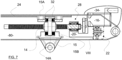
- Figure 4 shows in more detail the actuator according to a first embodiment of the invention.
- the "extent" to which it is referred to above i.e. the possibility of tilting or inclination of threaded rod 12 allowed by support element 22, is inferior to 2°, preferably about 1°.
- support element 22 provides direct support to threaded rod 12.
- support element 22 consists of a bearing provided with rolling elements, also known as rolling bearing. Specifically, it is a spherical roller bearing 22 that includes two ranges of rollers arranged between an inner ring and an outer ring. As shown on Figure 4 , outer ring is fixed relative to framework 80. Specifically, outer ring is integral with framework 80.
- bearing allows inner ring and/or outer ring to deviate from the initial configuration in which the central axis of inner ring is coincident (or superimposed) with that of outer ring.
- bearing is configured to allow the two rings to move one relative to the other and reach a configuration of misalignment where central axis of a first ring is not perfectly parallel to central axis of second ring.
- the bearing is designed so that it operates normally without reaching the end of the tilting possibility.
- this ball joint can compensate for poor coaxiality (i.e. misalignment) or undesired offset resulting from manufacturing imperfections and/or framework deformation under load during work conditions.
- rod 12 that can tilt relative to framework 80 is that it allows compensating a relative movement between the guiding means 24 and the rod 12, induced by a deformation of framework 80 and therefore that it prevents the generation of a misalignment between the guiding means (e.g. the rail 24) and the rod 12.
- rod 12 follows the movement/rotation of the guiding means by taking advantage of the specific design of support element 22 so that rod 12 and guiding means 24 remain parallel to each other and equidistant even if the framework 80 gets deformed.
- the framework of construction equipment deforms as its rigidity is limited for weight reasons. Accordingly, the guiding means that are attached to it also deform or move as a consequence of framework deformation.
- the spherical roller bearing 22 could be replaced by two back to back (or face to face) spherical roller thrust bearings (such as represented on Figure 10 ).
- any bearing or bearings combination that makes it possible for the inner ring to tilt and rotate relative to outer ring could be used. As all these bearings are available on the market, they are not detailed further.
- the actuator comprises a motor chassis 20 which supports/holds the electric motor 16.
- a bearing 28 connects the threaded rod 12 to the chassis 20.
- bearing 28 consists of a rolling bearing, e.g. needle bearing, defining a hole in which is received one end of rod 12. Said bearing 28 is integral with motor chassis 20.
- the motor chassis 20 bears the threaded rod 12 as the connection is achieved by one or more bearings.
- the verb "bear" is therefore employed only where the connection in question is achieved by a bearing element, such as rolling bearing or plain bearing.
- the threaded rod 12 and the electric motor 16 are indirectly connected to each other via the motor chassis 20, so that the motor 16, the motor chassis 20 and the threaded rod 12 form a single unit.
- carriage 15 is translationally or axially linked/connected with the nut 14 and its (translational/axial) movement is guided by rail 24.
- the carriage 15 is mounted around the nut 14 by means of a spherical plain bearing 17.
- This spherical plain bearing 17 is composed of two spherical parts nested inside each other. Specifically, the inside portion is part of the nut 14, while the outside portion belong to carriage 15. This makes it possible for the carriage 15 to tilt or incline, to some extent, around the nut 14 around any direction or axis crossing the center of the rings, similarly to a ball joint.
- the spherical contact characteristic of a spherical plain bearing is that it does not allow any translational degree of freedom, so that the nut and the carriage are fixed in translation/axially one relative to the other. Accordingly, translation of nut 14 resulting from rod rotation causes an axial movement of carriage 15 along rail 24.
- the spherical roller bearing 22 enables the threaded rod 12 to tilt, to some extent, relative to framework 80 around any axis perpendicular to rod longitudinal axis X12 (similarly to a ball joint).
- bearing 28, connecting rod 12 to motor 16 consists of a ball bearing that is fastened to motor chassis 20 using fasteners (not shown).
- bearing 28 could be replaced by any other rolling bearing, e.g. needle bearing or roller bearing.
- nut 14 is sandwiched by or within the carriage 15. This means that nut 14 is arranged axially in the center of the carriage 15 and that nut 14 is arranged axially between two portions of carriage 15. Accordingly, when the nut 14 is driven axially in translation, it abuts, directly or indirectly, against carriage 15 and push it so that it (i.e. the carriage) slides along the rail 24.
- the motor chassis 20 rests on at least one, preferably two or more elastic pads 36. This is to make sure that motor 16 does not move or tilt under its own weight and that it does not rotate about axis X12 because of resistive torque applied to motor 16. Also, the elastic nature of the pads 36 allows the movement of the rod 12 relative to the frame 80 to which it is referred to above since pads 36 can be compressed or stretched to absorb a tilting of rod 12.
- the main difference concerns the support element which, in this example, consists of a ball-and-socket joint (or ball joint) 22 arranged between the motor chassis 20 and the framework 80.
- This ball-and-socket joint 22 includes an inner portion, respectively the ball, and an outer portion, respectively the socket, which is integral with the motor chassis 20 and which is composed of at least one spherical shell complementary to the ball constituting the inner part.
- the inner part of the ball joint i.e. the ball
- Cylinder 30 extends perpendicularly from framework 80.
- the socket portion could be part of framework 80, while the ball portion could be part of motor chassis 20.
- rod 12 can tilt around any axis perpendicular to rod longitudinal axis X12.
- support element 22 which here consists of an elastic mount/assembly.
- the motor chassis 20 is provided with a stud/shaft 21 projecting/extending from the rest of the chassis along a longitudinal axis X21.
- axis X21 is parallel to axis X12 but it could be otherwise.
- said shaft 21 is engaged through a bore/hole delimited by a plate 30.
- damping devices e.g. elastic elements/mounts 32
- central flange 14A and collars 15B are arranged between central flange 14A and collars 15B. Thanks to their elastic nature, these damping devices 32 can get compressed or stretched and allow some tilting of nut 14 relative to carriage 15, or inversely.
- the elastic mount/assembly can be any other type of rubber mounts or elastic system.
- motor 16 is encased inside a carter or protection envelope/cover 34 that covers the portion of motor 16 that extends outside framework 80. This enables to protect the motor 16 from external elements, such as rain, rocks, dust, etc.
- this carter 34 can be fastened to the framework 80 using bolts rivets or screws (not shown).
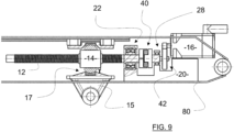
- Figure 9 represent a fifth embodiment of the invention, in which the motor chassis 20 directly rests on framework 80, which means that motor chassis 20 is fixed relative to framework 80.
- the elastic coupling 40 could be replaced by one or two cardan joints or any other type of elastic coupling.
- two bearings 28 support the output shaft of reducer 42. These two bearings are arranged on each side of larger pinion 42B of reducer 42.
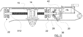
- a double angular contact spherical plain bearing is advantageously provided between the nut 14 and carriage 15.
- it could be replaced by a spherical plain bearing or by two back to back angular contact spherical plain bearings.
- Second ring of roller thrust bearing is fixed relative to machine framework 80.
- said second ring can be fastened to the framework 80 using bolts or rivets.
- Washer and first ring have complementary spherical contact surfaces, so that a spherical contact is achieved and a titling movement is therefore possible. More precisely, the assembly made of washer and first ring can tilt relative to second ring, similarly to ball jointing. This enables to compensate for any misalignment and/or offset caused by framework deformation and/or manufacturing tolerances.
Landscapes
- Engineering & Computer Science (AREA)
- Mechanical Engineering (AREA)
- General Engineering & Computer Science (AREA)
- Mining & Mineral Resources (AREA)
- Civil Engineering (AREA)
- Structural Engineering (AREA)
- Power Engineering (AREA)
- Physics & Mathematics (AREA)
- Chemical & Material Sciences (AREA)
- Combustion & Propulsion (AREA)
- Electromagnetism (AREA)
- Transmission Devices (AREA)
Claims (10)
- Équipement de construction (2), comprenant un cadre (80) et au moins un actionneur électrique (10.1, 10.2, 10.3) pour déplacer au moins un élément du cadre, dans lequel l'actionneur comprend- un système de vis à billes ou à rouleaux comprenant une tige filetée (12) et un écrou (14) formant une liaison hélicoïdale avec la tige filetée,- un moteur électrique (16) pour entraîner la tige (12) en rotation autour d'un axe longitudinal (X12), forçant ainsi l'écrou (14) à se déplacer axialement le long de la tige ;- un chariot (15) qui est relié axialement à l'écrou (14), et- des moyens de guidage axial (24) pour guider le mouvement du chariot (15), où les moyens de guidage sont fixés au cadre,l'équipement de construction (2) est caractérisé en ce que l'actionneur comprend en outre au moins un élément de soutien (22) qui relie, directement ou indirectement, une tige filetée (12) au cadre (80), dans lequel ledit élément de soutien (22) est un palier ou un agencement élastique conçu de sorte que la tige filetée puisse s'incliner, dans une certaine mesure, par rapport au cadre (80) autour de n'importe quel axe perpendiculaire à l'axe longitudinal (X12).
- Équipement de construction selon la revendication 1, dans lequel ledit élément de soutien (22) est un agencement de palier à roulement à l'intérieur duquel est reçue la tige filetée (12).
- Équipement de construction selon la revendication 2, dans lequel l'agencement de palier comprend au moins deux anneaux, parmi lesquels un premier anneau est configuré pour tourner conjointement avec la tige filetée et un second anneau est fixe par rapport au cadre (80).
- Équipement de construction selon la revendication 1, dans lequel ledit élément de soutien (22) est un support ou assemblage élastique, qui est de préférence constitué de deux éléments élastiques (23A, 23b) prévus sur les deux côtés d'une plaque (30) qui est fixe par rapport au cadre (80).
- Équipement de construction selon la revendication 1, dans lequel ledit élément de soutien (22) est un palier lisse ou un joint à rotule.
- Équipement de construction selon l'une des revendications précédentes, dans lequel l'actionneur comprend un châssis moteur (20) soutenant le moteur électrique (16) et au moins un palier à roulement (28), par exemple un palier à billes ou un palier à aiguilles, reliant la tige filetée (12) au châssis moteur (20).
- Équipement de construction selon l'une des revendications précédentes, dans lequel l'actionneur comprend un palier (17), par exemple un palier lisse sphérique ou un double palier lisse sphérique à contact oblique ou deux paliers lisses sphériques à contact oblique dos à dos, pour relier le chariot (15) autour de l'écrou (14).
- Équipement de construction selon l'une quelconque des revendications 1 à 6, dans lequel l'écrou (14) est pris en tenaille par le chariot (15) ou à l'intérieur de celui-ci le long de l'axe de tige (X12) et dans lequel au moins un élément (32), typiquement un disque sans frottement (par exemple en Téflon (marque déposée)) et/ou un coussin élastique, est interposé axialement de chaque côté entre l'écrou et le chariot.
- Équipement de construction selon l'une des revendications précédentes, dans lequel une extrémité de la tige filetée (12) est reliée à un arbre de sortie d'un organe de transmission (42) par l'intermédiaire d'un joint à cardan ou d'un agencement d'accouplement élastique (40).
- Équipement de construction selon l'une des revendications précédentes, dans lequel les moyens de guidage (24) comprennent au moins un rail fixé au cadre (80) et dans lequel le chariot (15) comprend au moins un vérin (15A) ayant une section transversale complémentaire à celle du rail, éventuellement avec des billes roulant entre le rail et le chariot.
Priority Applications (3)
| Application Number | Priority Date | Filing Date | Title |
|---|---|---|---|
| EP22200074.7A EP4350081B1 (fr) | 2022-10-06 | 2022-10-06 | Equipement de construction avec un agencement spécifique pour permettre un mouvement de titrage dans un actionneur électrique |
| CN202311175973.4A CN117846053A (zh) | 2022-10-06 | 2023-09-12 | 设有用于允许电动致动器内的倾斜移动的特定布置的建筑设备 |
| US18/480,852 US12291838B2 (en) | 2022-10-06 | 2023-10-04 | Construction equipment provided with a specific arrangement to allow titling movement within electric actuator |
Applications Claiming Priority (1)
| Application Number | Priority Date | Filing Date | Title |
|---|---|---|---|
| EP22200074.7A EP4350081B1 (fr) | 2022-10-06 | 2022-10-06 | Equipement de construction avec un agencement spécifique pour permettre un mouvement de titrage dans un actionneur électrique |
Publications (3)
| Publication Number | Publication Date |
|---|---|
| EP4350081A1 EP4350081A1 (fr) | 2024-04-10 |
| EP4350081C0 EP4350081C0 (fr) | 2024-07-17 |
| EP4350081B1 true EP4350081B1 (fr) | 2024-07-17 |
Family
ID=83688905
Family Applications (1)
| Application Number | Title | Priority Date | Filing Date |
|---|---|---|---|
| EP22200074.7A Active EP4350081B1 (fr) | 2022-10-06 | 2022-10-06 | Equipement de construction avec un agencement spécifique pour permettre un mouvement de titrage dans un actionneur électrique |
Country Status (3)
| Country | Link |
|---|---|
| US (1) | US12291838B2 (fr) |
| EP (1) | EP4350081B1 (fr) |
| CN (1) | CN117846053A (fr) |
Families Citing this family (2)
| Publication number | Priority date | Publication date | Assignee | Title |
|---|---|---|---|---|
| CN118327693B (zh) * | 2024-06-12 | 2024-09-06 | 贵州大学 | 一种矿山动力灾害自动监测预警装置 |
| US20260027700A1 (en) * | 2024-07-23 | 2026-01-29 | Point Robotics Medtech Inc. | Transmission device having platform with multiple degrees of freedom |
Family Cites Families (10)
| Publication number | Priority date | Publication date | Assignee | Title |
|---|---|---|---|---|
| US2918786A (en) * | 1955-12-12 | 1959-12-29 | Gen Motors Corp | Dual drive actuator |
| JPS63300131A (ja) * | 1987-05-30 | 1988-12-07 | Shin Caterpillar Mitsubishi Ltd | 電気パワ−ショベル |
| FR2782467B1 (fr) * | 1998-08-19 | 2000-09-15 | Commissariat Energie Atomique | Element de liaison a verin a vis et ecrou et son application un bras de robot |
| US8960031B2 (en) * | 2009-09-01 | 2015-02-24 | Parker-Hannifin Corporation | Aircraft stabilizer actuator |
| US8291782B1 (en) * | 2009-09-30 | 2012-10-23 | Rockwell Collins, Inc. | Actuator assembly for stabilizers |
| JP5547563B2 (ja) * | 2010-06-25 | 2014-07-16 | Ntn株式会社 | 電動アクチュエータ |
| CN203008004U (zh) * | 2012-12-28 | 2013-06-19 | 广西大学 | 一种螺杆传动多自由度可控机构式挖掘机构 |
| WO2016097784A1 (fr) * | 2014-12-16 | 2016-06-23 | Volvo Construction Equipment Ab | Bras d'excavateur, élément en porte-à-faux d'excavateur comprenant un tel bras d'excavateur et excavateur comprenant un tel élément en porte-à-faux d'excavateur |
| US10228046B2 (en) * | 2016-12-21 | 2019-03-12 | Caterpillar Inc. | Electric linear actuator having planetary gear arrangement |
| EP4036316A1 (fr) | 2021-02-02 | 2022-08-03 | Volvo Construction Equipment AB | Équipement de construction avec au moins un actionneur électrique |
-
2022
- 2022-10-06 EP EP22200074.7A patent/EP4350081B1/fr active Active
-
2023
- 2023-09-12 CN CN202311175973.4A patent/CN117846053A/zh active Pending
- 2023-10-04 US US18/480,852 patent/US12291838B2/en active Active
Also Published As
| Publication number | Publication date |
|---|---|
| EP4350081C0 (fr) | 2024-07-17 |
| US12291838B2 (en) | 2025-05-06 |
| US20240117591A1 (en) | 2024-04-11 |
| CN117846053A (zh) | 2024-04-09 |
| EP4350081A1 (fr) | 2024-04-10 |
Similar Documents
| Publication | Publication Date | Title |
|---|---|---|
| US12291838B2 (en) | Construction equipment provided with a specific arrangement to allow titling movement within electric actuator | |
| KR102727972B1 (ko) | 건설 장비 | |
| US20200263763A1 (en) | Construction Machine With Flywheel Arrangement | |
| US20230183940A1 (en) | Drive transmission device and construction machine, and method of assembling construction machine | |
| CN102888810B (zh) | 自行式表面铣刨机 | |
| CN107110353A (zh) | 用于机器的接头的密封构件及其组装方法 | |
| JP2013072489A (ja) | 作業機械の軸部シール構造 | |
| CN115246162B (zh) | 一种劈裂机外力消除装置 | |
| CN104018530A (zh) | 工程机械 | |
| KR930006596B1 (ko) | 무한궤도차량용 구동시스템 | |
| CN217195347U (zh) | 一种小型破拆机器人 | |
| EP4570994A1 (fr) | Equipement de construction comprenant au moins un actionneur électrique | |
| CN111108247A (zh) | 作业机械的作业臂 | |
| US20230392349A1 (en) | Construction equipment | |
| CN1847614B (zh) | 用于地下开采的采掘机 | |
| CN223686696U (zh) | 适配tbm的矮机面履带底盘 | |
| RU2593290C2 (ru) | Основная рама и машина с указанной основной рамой | |
| CN110778563A (zh) | 一种用于液压缸的滚轮支撑装置 | |
| US20250333927A1 (en) | Dozer blade drive mechanism | |
| KR102750774B1 (ko) | 차량용 코너 모듈 | |
| CN114852123B (zh) | 推头总成、推车节及推车机 | |
| CN121295779A (zh) | 一种伸缩臂多功能滑移装载机及智能监控系统 | |
| JP6403604B2 (ja) | 電動アクチュエータ | |
| CN117400233A (zh) | 一种机载液压机械臂及工作方法 | |
| CN117868247A (zh) | 一种铲运机 |
Legal Events
| Date | Code | Title | Description |
|---|---|---|---|
| PUAI | Public reference made under article 153(3) epc to a published international application that has entered the european phase |
Free format text: ORIGINAL CODE: 0009012 |
|
| STAA | Information on the status of an ep patent application or granted ep patent |
Free format text: STATUS: REQUEST FOR EXAMINATION WAS MADE |
|
| 17P | Request for examination filed |
Effective date: 20230728 |
|
| AK | Designated contracting states |
Kind code of ref document: A1 Designated state(s): AL AT BE BG CH CY CZ DE DK EE ES FI FR GB GR HR HU IE IS IT LI LT LU LV MC ME MK MT NL NO PL PT RO RS SE SI SK SM TR |
|
| REG | Reference to a national code |
Ref country code: DE Ref legal event code: R079 Free format text: PREVIOUS MAIN CLASS: E02F0003380000 Ipc: F16H0025200000 Ref country code: DE Ref legal event code: R079 Ref document number: 602022004611 Country of ref document: DE Free format text: PREVIOUS MAIN CLASS: E02F0003380000 Ipc: F16H0025200000 |
|
| GRAP | Despatch of communication of intention to grant a patent |
Free format text: ORIGINAL CODE: EPIDOSNIGR1 |
|
| STAA | Information on the status of an ep patent application or granted ep patent |
Free format text: STATUS: GRANT OF PATENT IS INTENDED |
|
| RIC1 | Information provided on ipc code assigned before grant |
Ipc: F16H 25/22 20060101ALI20240411BHEP Ipc: E02F 9/20 20060101ALI20240411BHEP Ipc: E02F 3/38 20060101ALI20240411BHEP Ipc: F16H 25/20 20060101AFI20240411BHEP |
|
| INTG | Intention to grant announced |
Effective date: 20240502 |
|
| GRAS | Grant fee paid |
Free format text: ORIGINAL CODE: EPIDOSNIGR3 |
|
| GRAA | (expected) grant |
Free format text: ORIGINAL CODE: 0009210 |
|
| STAA | Information on the status of an ep patent application or granted ep patent |
Free format text: STATUS: THE PATENT HAS BEEN GRANTED |
|
| AK | Designated contracting states |
Kind code of ref document: B1 Designated state(s): AL AT BE BG CH CY CZ DE DK EE ES FI FR GB GR HR HU IE IS IT LI LT LU LV MC ME MK MT NL NO PL PT RO RS SE SI SK SM TR |
|
| REG | Reference to a national code |
Ref country code: CH Ref legal event code: EP |
|
| REG | Reference to a national code |
Ref country code: DE Ref legal event code: R096 Ref document number: 602022004611 Country of ref document: DE |
|
| REG | Reference to a national code |
Ref country code: IE Ref legal event code: FG4D |
|
| U01 | Request for unitary effect filed |
Effective date: 20240807 |
|
| U07 | Unitary effect registered |
Designated state(s): AT BE BG DE DK EE FI FR IT LT LU LV MT NL PT SE SI Effective date: 20240823 |
|
| U20 | Renewal fee for the european patent with unitary effect paid |
Year of fee payment: 3 Effective date: 20240826 |
|
| PG25 | Lapsed in a contracting state [announced via postgrant information from national office to epo] |
Ref country code: NO Free format text: LAPSE BECAUSE OF FAILURE TO SUBMIT A TRANSLATION OF THE DESCRIPTION OR TO PAY THE FEE WITHIN THE PRESCRIBED TIME-LIMIT Effective date: 20241017 |
|
| PG25 | Lapsed in a contracting state [announced via postgrant information from national office to epo] |
Ref country code: PL Free format text: LAPSE BECAUSE OF FAILURE TO SUBMIT A TRANSLATION OF THE DESCRIPTION OR TO PAY THE FEE WITHIN THE PRESCRIBED TIME-LIMIT Effective date: 20240717 Ref country code: GR Free format text: LAPSE BECAUSE OF FAILURE TO SUBMIT A TRANSLATION OF THE DESCRIPTION OR TO PAY THE FEE WITHIN THE PRESCRIBED TIME-LIMIT Effective date: 20241018 |
|
| PG25 | Lapsed in a contracting state [announced via postgrant information from national office to epo] |
Ref country code: IS Free format text: LAPSE BECAUSE OF FAILURE TO SUBMIT A TRANSLATION OF THE DESCRIPTION OR TO PAY THE FEE WITHIN THE PRESCRIBED TIME-LIMIT Effective date: 20241117 |
|
| PG25 | Lapsed in a contracting state [announced via postgrant information from national office to epo] |
Ref country code: HR Free format text: LAPSE BECAUSE OF FAILURE TO SUBMIT A TRANSLATION OF THE DESCRIPTION OR TO PAY THE FEE WITHIN THE PRESCRIBED TIME-LIMIT Effective date: 20240717 |
|
| PG25 | Lapsed in a contracting state [announced via postgrant information from national office to epo] |
Ref country code: ES Free format text: LAPSE BECAUSE OF FAILURE TO SUBMIT A TRANSLATION OF THE DESCRIPTION OR TO PAY THE FEE WITHIN THE PRESCRIBED TIME-LIMIT Effective date: 20240717 Ref country code: RS Free format text: LAPSE BECAUSE OF FAILURE TO SUBMIT A TRANSLATION OF THE DESCRIPTION OR TO PAY THE FEE WITHIN THE PRESCRIBED TIME-LIMIT Effective date: 20241017 |
|
| PG25 | Lapsed in a contracting state [announced via postgrant information from national office to epo] |
Ref country code: RS Free format text: LAPSE BECAUSE OF FAILURE TO SUBMIT A TRANSLATION OF THE DESCRIPTION OR TO PAY THE FEE WITHIN THE PRESCRIBED TIME-LIMIT Effective date: 20241017 Ref country code: PL Free format text: LAPSE BECAUSE OF FAILURE TO SUBMIT A TRANSLATION OF THE DESCRIPTION OR TO PAY THE FEE WITHIN THE PRESCRIBED TIME-LIMIT Effective date: 20240717 Ref country code: NO Free format text: LAPSE BECAUSE OF FAILURE TO SUBMIT A TRANSLATION OF THE DESCRIPTION OR TO PAY THE FEE WITHIN THE PRESCRIBED TIME-LIMIT Effective date: 20241017 Ref country code: IS Free format text: LAPSE BECAUSE OF FAILURE TO SUBMIT A TRANSLATION OF THE DESCRIPTION OR TO PAY THE FEE WITHIN THE PRESCRIBED TIME-LIMIT Effective date: 20241117 Ref country code: HR Free format text: LAPSE BECAUSE OF FAILURE TO SUBMIT A TRANSLATION OF THE DESCRIPTION OR TO PAY THE FEE WITHIN THE PRESCRIBED TIME-LIMIT Effective date: 20240717 Ref country code: GR Free format text: LAPSE BECAUSE OF FAILURE TO SUBMIT A TRANSLATION OF THE DESCRIPTION OR TO PAY THE FEE WITHIN THE PRESCRIBED TIME-LIMIT Effective date: 20241018 Ref country code: ES Free format text: LAPSE BECAUSE OF FAILURE TO SUBMIT A TRANSLATION OF THE DESCRIPTION OR TO PAY THE FEE WITHIN THE PRESCRIBED TIME-LIMIT Effective date: 20240717 |
|
| PG25 | Lapsed in a contracting state [announced via postgrant information from national office to epo] |
Ref country code: SM Free format text: LAPSE BECAUSE OF FAILURE TO SUBMIT A TRANSLATION OF THE DESCRIPTION OR TO PAY THE FEE WITHIN THE PRESCRIBED TIME-LIMIT Effective date: 20240717 |
|
| PG25 | Lapsed in a contracting state [announced via postgrant information from national office to epo] |
Ref country code: CZ Free format text: LAPSE BECAUSE OF FAILURE TO SUBMIT A TRANSLATION OF THE DESCRIPTION OR TO PAY THE FEE WITHIN THE PRESCRIBED TIME-LIMIT Effective date: 20240717 |
|
| PG25 | Lapsed in a contracting state [announced via postgrant information from national office to epo] |
Ref country code: SK Free format text: LAPSE BECAUSE OF FAILURE TO SUBMIT A TRANSLATION OF THE DESCRIPTION OR TO PAY THE FEE WITHIN THE PRESCRIBED TIME-LIMIT Effective date: 20240717 |
|
| PLBE | No opposition filed within time limit |
Free format text: ORIGINAL CODE: 0009261 |
|
| STAA | Information on the status of an ep patent application or granted ep patent |
Free format text: STATUS: NO OPPOSITION FILED WITHIN TIME LIMIT |
|
| 26N | No opposition filed |
Effective date: 20250422 |
|
| PG25 | Lapsed in a contracting state [announced via postgrant information from national office to epo] |
Ref country code: MC Free format text: LAPSE BECAUSE OF FAILURE TO SUBMIT A TRANSLATION OF THE DESCRIPTION OR TO PAY THE FEE WITHIN THE PRESCRIBED TIME-LIMIT Effective date: 20240717 |
|
| PG25 | Lapsed in a contracting state [announced via postgrant information from national office to epo] |
Ref country code: IE Free format text: LAPSE BECAUSE OF NON-PAYMENT OF DUE FEES Effective date: 20241006 |
|
| PG25 | Lapsed in a contracting state [announced via postgrant information from national office to epo] |
Ref country code: RO Free format text: LAPSE BECAUSE OF FAILURE TO SUBMIT A TRANSLATION OF THE DESCRIPTION OR TO PAY THE FEE WITHIN THE PRESCRIBED TIME-LIMIT Effective date: 20240717 |
|
| U20 | Renewal fee for the european patent with unitary effect paid |
Year of fee payment: 4 Effective date: 20251027 |
|
| PG25 | Lapsed in a contracting state [announced via postgrant information from national office to epo] |
Ref country code: CY Free format text: LAPSE BECAUSE OF FAILURE TO SUBMIT A TRANSLATION OF THE DESCRIPTION OR TO PAY THE FEE WITHIN THE PRESCRIBED TIME-LIMIT; INVALID AB INITIO Effective date: 20221006 |