EP4350049A2 - Ammoniakherstellungsvorrichtung und ammoniakherstellungsverfahren - Google Patents
Ammoniakherstellungsvorrichtung und ammoniakherstellungsverfahren Download PDFInfo
- Publication number
- EP4350049A2 EP4350049A2 EP23162041.0A EP23162041A EP4350049A2 EP 4350049 A2 EP4350049 A2 EP 4350049A2 EP 23162041 A EP23162041 A EP 23162041A EP 4350049 A2 EP4350049 A2 EP 4350049A2
- Authority
- EP
- European Patent Office
- Prior art keywords
- ammonia
- reaction tank
- electrolytic solution
- nitrogen
- electrode
- Prior art date
- Legal status (The legal status is an assumption and is not a legal conclusion. Google has not performed a legal analysis and makes no representation as to the accuracy of the status listed.)
- Pending
Links
Images
Classifications
-
- C—CHEMISTRY; METALLURGY
- C25—ELECTROLYTIC OR ELECTROPHORETIC PROCESSES; APPARATUS THEREFOR
- C25B—ELECTROLYTIC OR ELECTROPHORETIC PROCESSES FOR THE PRODUCTION OF COMPOUNDS OR NON-METALS; APPARATUS THEREFOR
- C25B1/00—Electrolytic production of inorganic compounds or non-metals
- C25B1/01—Products
- C25B1/27—Ammonia
-
- B—PERFORMING OPERATIONS; TRANSPORTING
- B01—PHYSICAL OR CHEMICAL PROCESSES OR APPARATUS IN GENERAL
- B01J—CHEMICAL OR PHYSICAL PROCESSES, e.g. CATALYSIS OR COLLOID CHEMISTRY; THEIR RELEVANT APPARATUS
- B01J23/00—Catalysts comprising metals or metal oxides or hydroxides, not provided for in group B01J21/00
- B01J23/16—Catalysts comprising metals or metal oxides or hydroxides, not provided for in group B01J21/00 of arsenic, antimony, bismuth, vanadium, niobium, tantalum, polonium, chromium, molybdenum, tungsten, manganese, technetium or rhenium
- B01J23/24—Chromium, molybdenum or tungsten
- B01J23/28—Molybdenum
-
- B—PERFORMING OPERATIONS; TRANSPORTING
- B01—PHYSICAL OR CHEMICAL PROCESSES OR APPARATUS IN GENERAL
- B01J—CHEMICAL OR PHYSICAL PROCESSES, e.g. CATALYSIS OR COLLOID CHEMISTRY; THEIR RELEVANT APPARATUS
- B01J31/00—Catalysts comprising hydrides, coordination complexes or organic compounds
- B01J31/16—Catalysts comprising hydrides, coordination complexes or organic compounds containing coordination complexes
- B01J31/18—Catalysts comprising hydrides, coordination complexes or organic compounds containing coordination complexes containing nitrogen, phosphorus, arsenic or antimony as complexing atoms, e.g. in pyridine ligands, or in resonance therewith, e.g. in isocyanide ligands C=N-R or as complexed central atoms
-
- B—PERFORMING OPERATIONS; TRANSPORTING
- B01—PHYSICAL OR CHEMICAL PROCESSES OR APPARATUS IN GENERAL
- B01J—CHEMICAL OR PHYSICAL PROCESSES, e.g. CATALYSIS OR COLLOID CHEMISTRY; THEIR RELEVANT APPARATUS
- B01J31/00—Catalysts comprising hydrides, coordination complexes or organic compounds
- B01J31/16—Catalysts comprising hydrides, coordination complexes or organic compounds containing coordination complexes
- B01J31/22—Organic complexes
- B01J31/2265—Carbenes or carbynes, i.e.(image)
- B01J31/2269—Heterocyclic carbenes
- B01J31/2273—Heterocyclic carbenes with only nitrogen as heteroatomic ring members, e.g. 1,3-diarylimidazoline-2-ylidenes
-
- B—PERFORMING OPERATIONS; TRANSPORTING
- B01—PHYSICAL OR CHEMICAL PROCESSES OR APPARATUS IN GENERAL
- B01J—CHEMICAL OR PHYSICAL PROCESSES, e.g. CATALYSIS OR COLLOID CHEMISTRY; THEIR RELEVANT APPARATUS
- B01J31/00—Catalysts comprising hydrides, coordination complexes or organic compounds
- B01J31/16—Catalysts comprising hydrides, coordination complexes or organic compounds containing coordination complexes
- B01J31/24—Phosphines, i.e. phosphorus bonded to only carbon atoms, or to both carbon and hydrogen atoms, including e.g. sp2-hybridised phosphorus compounds such as phosphabenzene, phosphole or anionic phospholide ligands
-
- C—CHEMISTRY; METALLURGY
- C01—INORGANIC CHEMISTRY
- C01C—AMMONIA; CYANOGEN; COMPOUNDS THEREOF
- C01C1/00—Ammonia; Compounds thereof
- C01C1/02—Preparation, purification or separation of ammonia
- C01C1/04—Preparation of ammonia by synthesis
- C01C1/0405—Preparation of ammonia by synthesis from N2 and H2 in presence of a catalyst
- C01C1/0458—Separation of NH3
-
- C—CHEMISTRY; METALLURGY
- C25—ELECTROLYTIC OR ELECTROPHORETIC PROCESSES; APPARATUS THEREFOR
- C25B—ELECTROLYTIC OR ELECTROPHORETIC PROCESSES FOR THE PRODUCTION OF COMPOUNDS OR NON-METALS; APPARATUS THEREFOR
- C25B1/00—Electrolytic production of inorganic compounds or non-metals
- C25B1/50—Processes
-
- C—CHEMISTRY; METALLURGY
- C25—ELECTROLYTIC OR ELECTROPHORETIC PROCESSES; APPARATUS THEREFOR
- C25B—ELECTROLYTIC OR ELECTROPHORETIC PROCESSES FOR THE PRODUCTION OF COMPOUNDS OR NON-METALS; APPARATUS THEREFOR
- C25B11/00—Electrodes; Manufacture thereof not otherwise provided for
- C25B11/02—Electrodes; Manufacture thereof not otherwise provided for characterised by shape or form
- C25B11/03—Electrodes; Manufacture thereof not otherwise provided for characterised by shape or form perforated or foraminous
- C25B11/031—Porous electrodes
-
- C—CHEMISTRY; METALLURGY
- C25—ELECTROLYTIC OR ELECTROPHORETIC PROCESSES; APPARATUS THEREFOR
- C25B—ELECTROLYTIC OR ELECTROPHORETIC PROCESSES FOR THE PRODUCTION OF COMPOUNDS OR NON-METALS; APPARATUS THEREFOR
- C25B11/00—Electrodes; Manufacture thereof not otherwise provided for
- C25B11/04—Electrodes; Manufacture thereof not otherwise provided for characterised by the material
- C25B11/051—Electrodes formed of electrocatalysts on a substrate or carrier
- C25B11/052—Electrodes comprising one or more electrocatalytic coatings on a substrate
-
- C—CHEMISTRY; METALLURGY
- C25—ELECTROLYTIC OR ELECTROPHORETIC PROCESSES; APPARATUS THEREFOR
- C25B—ELECTROLYTIC OR ELECTROPHORETIC PROCESSES FOR THE PRODUCTION OF COMPOUNDS OR NON-METALS; APPARATUS THEREFOR
- C25B11/00—Electrodes; Manufacture thereof not otherwise provided for
- C25B11/04—Electrodes; Manufacture thereof not otherwise provided for characterised by the material
- C25B11/051—Electrodes formed of electrocatalysts on a substrate or carrier
- C25B11/055—Electrodes formed of electrocatalysts on a substrate or carrier characterised by the substrate or carrier material
- C25B11/057—Electrodes formed of electrocatalysts on a substrate or carrier characterised by the substrate or carrier material consisting of a single element or compound
- C25B11/065—Carbon
-
- C—CHEMISTRY; METALLURGY
- C25—ELECTROLYTIC OR ELECTROPHORETIC PROCESSES; APPARATUS THEREFOR
- C25B—ELECTROLYTIC OR ELECTROPHORETIC PROCESSES FOR THE PRODUCTION OF COMPOUNDS OR NON-METALS; APPARATUS THEREFOR
- C25B11/00—Electrodes; Manufacture thereof not otherwise provided for
- C25B11/04—Electrodes; Manufacture thereof not otherwise provided for characterised by the material
- C25B11/051—Electrodes formed of electrocatalysts on a substrate or carrier
- C25B11/055—Electrodes formed of electrocatalysts on a substrate or carrier characterised by the substrate or carrier material
- C25B11/069—Electrodes formed of electrocatalysts on a substrate or carrier characterised by the substrate or carrier material consisting of at least one single element and at least one compound; consisting of two or more compounds
-
- C—CHEMISTRY; METALLURGY
- C25—ELECTROLYTIC OR ELECTROPHORETIC PROCESSES; APPARATUS THEREFOR
- C25B—ELECTROLYTIC OR ELECTROPHORETIC PROCESSES FOR THE PRODUCTION OF COMPOUNDS OR NON-METALS; APPARATUS THEREFOR
- C25B11/00—Electrodes; Manufacture thereof not otherwise provided for
- C25B11/04—Electrodes; Manufacture thereof not otherwise provided for characterised by the material
- C25B11/051—Electrodes formed of electrocatalysts on a substrate or carrier
- C25B11/073—Electrodes formed of electrocatalysts on a substrate or carrier characterised by the electrocatalyst material
-
- C—CHEMISTRY; METALLURGY
- C25—ELECTROLYTIC OR ELECTROPHORETIC PROCESSES; APPARATUS THEREFOR
- C25B—ELECTROLYTIC OR ELECTROPHORETIC PROCESSES FOR THE PRODUCTION OF COMPOUNDS OR NON-METALS; APPARATUS THEREFOR
- C25B11/00—Electrodes; Manufacture thereof not otherwise provided for
- C25B11/04—Electrodes; Manufacture thereof not otherwise provided for characterised by the material
- C25B11/051—Electrodes formed of electrocatalysts on a substrate or carrier
- C25B11/073—Electrodes formed of electrocatalysts on a substrate or carrier characterised by the electrocatalyst material
- C25B11/075—Electrodes formed of electrocatalysts on a substrate or carrier characterised by the electrocatalyst material consisting of a single catalytic element or catalytic compound
- C25B11/085—Organic compound
-
- C—CHEMISTRY; METALLURGY
- C25—ELECTROLYTIC OR ELECTROPHORETIC PROCESSES; APPARATUS THEREFOR
- C25B—ELECTROLYTIC OR ELECTROPHORETIC PROCESSES FOR THE PRODUCTION OF COMPOUNDS OR NON-METALS; APPARATUS THEREFOR
- C25B15/00—Operating or servicing cells
- C25B15/08—Supplying or removing reactants or electrolytes; Regeneration of electrolytes
- C25B15/083—Separating products
-
- C—CHEMISTRY; METALLURGY
- C25—ELECTROLYTIC OR ELECTROPHORETIC PROCESSES; APPARATUS THEREFOR
- C25B—ELECTROLYTIC OR ELECTROPHORETIC PROCESSES FOR THE PRODUCTION OF COMPOUNDS OR NON-METALS; APPARATUS THEREFOR
- C25B9/00—Cells or assemblies of cells; Constructional parts of cells; Assemblies of constructional parts, e.g. electrode-diaphragm assemblies; Process-related cell features
- C25B9/17—Cells comprising dimensionally-stable non-movable electrodes; Assemblies of constructional parts thereof
- C25B9/19—Cells comprising dimensionally-stable non-movable electrodes; Assemblies of constructional parts thereof with diaphragms
-
- C—CHEMISTRY; METALLURGY
- C25—ELECTROLYTIC OR ELECTROPHORETIC PROCESSES; APPARATUS THEREFOR
- C25B—ELECTROLYTIC OR ELECTROPHORETIC PROCESSES FOR THE PRODUCTION OF COMPOUNDS OR NON-METALS; APPARATUS THEREFOR
- C25B9/00—Cells or assemblies of cells; Constructional parts of cells; Assemblies of constructional parts, e.g. electrode-diaphragm assemblies; Process-related cell features
- C25B9/17—Cells comprising dimensionally-stable non-movable electrodes; Assemblies of constructional parts thereof
- C25B9/19—Cells comprising dimensionally-stable non-movable electrodes; Assemblies of constructional parts thereof with diaphragms
- C25B9/23—Cells comprising dimensionally-stable non-movable electrodes; Assemblies of constructional parts thereof with diaphragms comprising ion-exchange membranes in or on which electrode material is embedded
-
- C—CHEMISTRY; METALLURGY
- C25—ELECTROLYTIC OR ELECTROPHORETIC PROCESSES; APPARATUS THEREFOR
- C25B—ELECTROLYTIC OR ELECTROPHORETIC PROCESSES FOR THE PRODUCTION OF COMPOUNDS OR NON-METALS; APPARATUS THEREFOR
- C25B9/00—Cells or assemblies of cells; Constructional parts of cells; Assemblies of constructional parts, e.g. electrode-diaphragm assemblies; Process-related cell features
- C25B9/70—Assemblies comprising two or more cells
-
- B—PERFORMING OPERATIONS; TRANSPORTING
- B01—PHYSICAL OR CHEMICAL PROCESSES OR APPARATUS IN GENERAL
- B01J—CHEMICAL OR PHYSICAL PROCESSES, e.g. CATALYSIS OR COLLOID CHEMISTRY; THEIR RELEVANT APPARATUS
- B01J2231/00—Catalytic reactions performed with catalysts classified in B01J31/00
- B01J2231/60—Reduction reactions, e.g. hydrogenation
- B01J2231/62—Reductions in general of inorganic substrates, e.g. formal hydrogenation, e.g. of N2
-
- B—PERFORMING OPERATIONS; TRANSPORTING
- B01—PHYSICAL OR CHEMICAL PROCESSES OR APPARATUS IN GENERAL
- B01J—CHEMICAL OR PHYSICAL PROCESSES, e.g. CATALYSIS OR COLLOID CHEMISTRY; THEIR RELEVANT APPARATUS
- B01J2531/00—Additional information regarding catalytic systems classified in B01J31/00
- B01J2531/02—Compositional aspects of complexes used, e.g. polynuclearity
- B01J2531/0238—Complexes comprising multidentate ligands, i.e. more than 2 ionic or coordinative bonds from the central metal to the ligand, the latter having at least two donor atoms, e.g. N, O, S, P
- B01J2531/0241—Rigid ligands, e.g. extended sp2-carbon frameworks or geminal di- or trisubstitution
- B01J2531/0244—Pincer-type complexes, i.e. consisting of a tridentate skeleton bound to a metal, e.g. by one to three metal-carbon sigma-bonds
-
- B—PERFORMING OPERATIONS; TRANSPORTING
- B01—PHYSICAL OR CHEMICAL PROCESSES OR APPARATUS IN GENERAL
- B01J—CHEMICAL OR PHYSICAL PROCESSES, e.g. CATALYSIS OR COLLOID CHEMISTRY; THEIR RELEVANT APPARATUS
- B01J2531/00—Additional information regarding catalytic systems classified in B01J31/00
- B01J2531/60—Complexes comprising metals of Group VI (VIA or VIB) as the central metal
- B01J2531/64—Molybdenum
-
- C—CHEMISTRY; METALLURGY
- C25—ELECTROLYTIC OR ELECTROPHORETIC PROCESSES; APPARATUS THEREFOR
- C25B—ELECTROLYTIC OR ELECTROPHORETIC PROCESSES FOR THE PRODUCTION OF COMPOUNDS OR NON-METALS; APPARATUS THEREFOR
- C25B15/00—Operating or servicing cells
- C25B15/08—Supplying or removing reactants or electrolytes; Regeneration of electrolytes
- C25B15/087—Recycling of electrolyte to electrochemical cell
Definitions
- Arrangements disclosed herein relate generally to an ammonia manufacturing apparatus and an ammonia manufacturing method.
- the amount of production of ammonia is about 140 million tons in the world in a year and continues to rise. About 80% of the amount of production is utilized as a raw material for fertilizer and is mainly converted to other nitrogen compounds such as urea, nitric acid, ammonium nitrate, and ammonium sulfate. On the other hand, the remaining 20% thereof is utilized for manufacture of synthetic resin and fiber. To cope with the global population growth, the shortage of cultivated acreage, and the food shortages due to the sophistication of diet mainly in developing countries, an increase in demand for ammonia is inevitable. Besides, ammonia attracts attention when used as an energy carrier owing to its ease of handling, high energy density, and a characteristic of containing no carbon and emitting no carbon dioxide when used.
- ammonia is industrially synthesized from hydrogen gas and nitrogen gas derived from fossil fuels such as petroleum, coal, or natural gas by the method called the Haber-Bosh process invented about 100 years ago.
- This synthesis reaction requires severe conditions such as high temperature (400 to 650°C) and high pressure (200 to 400 atm), consumes 1.2% of total energy in the world, and emits a large amount of carbon dioxide.
- high temperature 400 to 650°C
- high pressure 200 to 400 atm
- a catalyst for producing ammonia from nitrogen at normal temperature and pressure is under development.
- a molybdenum iodide complex having a PNP (2,6-bis(di-tert-butylphosphinomethyl)pyridine) ligand as a catalyst, alcohol or water as a proton source, and a solution containing a halide (II) of a lanthanoid metal, for example, samarium (II) iodide as a reducing agent are stirred in the presence of nitrogen gas at normal temperature to thereby produce up to 4350 equivalents of ammonia per catalyst.
- the production reaction of ammonia needs to use a stoichiometric amount of expensive samarium (II) iodide for the reducing agent. Further, the reaction can be controlled only within the amount of the reducing agent. Therefore, from an industrial standpoint, there is a need for a manufacturing method that allows control of the reaction at a low cost, and can efficiently produce and recover ammonia. It is desirable to develop an ammonia manufacturing apparatus and manufacturing method that can manufacture ammonia with high efficiency and efficiently recover the manufactured ammonia.
- a problem to be solved by the present invention is to provide an ammonia manufacturing apparatus and an ammonia manufacturing method that enable highly efficient manufacturing of ammonia.
- an ammonia manufacturing apparatus and an ammonia manufacturing method that enable highly efficient manufacturing of ammonia are provided.
- An ammonia manufacturing apparatus of an arrangement includes: an electrochemical reaction cell including a first reaction tank in which a reduction electrode is arranged and gaseous nitrogen is supplied; a second reaction tank in which an oxidation electrode is arranged and an electrolytic solution containing water or water vapor is supplied, and a diaphragm provided between the first reaction tank and the second reaction tank.
- the reduction electrode includes a reduction catalyst that reduces nitrogen to produce ammonia, a porous carbon material that supports the reduction catalyst, and an organic polymer material that binds the porous carbon material.
- the porous carbon material has pores with a BET average pore size of 1 nm or more and 15 nm or less.
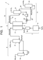
- FIG. 1 is a view illustrating an ammonia manufacturing apparatus 1 of an arrangement.
- the ammonia manufacturing apparatus 1 illustrated in FIG. 1 includes: an electrochemical reaction unit (electrolysis cell) 5 including a first reaction tank (reduction reaction electrolytic bath) 2 to which gaseous nitrogen is supplied, a second reaction tank (oxidation reaction electrolytic bath) 3 to which an electrolytic solution containing water or water vapor is supplied, and a diaphragm 4; a nitrogen supply unit 7 including a nitrogen supply part (supplier) 6 for supplying nitrogen to the first reaction tank 2; an ammonia collection unit 9 including a collection part (collector) 8 for collecting ammonia contained in the gas exhausted from the first reaction tank 2, and an ammonia separation unit 11 including an ammonia separation part (separator) 10 for separating ammonia contained in the electrolytic solution discharged from the second reaction tank 3.
- the ammonia manufacturing apparatus 1 further includes an electrolytic solution circulation unit 13 including a circulation pipe 12 for circulating the electrolytic solution accommodated in the second reaction
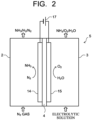
- FIG. 2 illustrates a first example of the electrochemical reaction unit 5.
- the electrochemical reaction unit 5 illustrated in FIG. 2 includes the first reaction tank (reduction reaction electrolytic bath) 2, the second reaction tank (oxidation reaction electrolytic bath) 3, the diaphragm 4 provided between the first reaction tank 2 and the second reaction tank 3, a reduction electrode 14 arranged in the first reaction tank 2 and used for an electrochemical reduction reaction, and an oxidation electrode 15 arranged in the second reaction tank 3 and used for an electrochemical oxidation reaction, and these constitute an electrochemical reaction cell (electrolysis cell).
- the electrochemical reaction cell 5 is partitioned into the first reaction tank 2 and the second reaction tank 3 by the diaphragm 4 capable of moving ions such as hydrogen ions (H + ) and hydroxide ions (OH - ).
- Gaseous nitrogen (N 2 ) is supplied to the first reaction tank 2 through a pipe.
- the electrolytic solution containing water (H 2 O) or water vapor (H 2 O) is supplied through the circulation pipe 12.
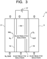
- the electrochemical reaction unit 5 may have the configuration illustrated in FIG. 3.
- FIG. 3 illustrates a second example of the electrochemical reaction unit 5.
- the electrochemical reaction unit 5 illustrated in FIG. 3 includes a third reaction tank 16, to which an electrolytic solution (cathode solution) containing water is supplied, provided between the first reaction tank 2, to which gaseous nitrogen (N 2 ) is supplied, and the diaphragm 4.
- the first reaction tank 2 and the third reaction tank 16 are in contact with each other through the reduction electrode 14 in a porous state, and they form a cathode chamber.
- the cathode chamber with the first reaction tank 2 and the third reaction tank 16 is in contact with the second reaction tank 3 as an anode chamber through the diaphragm 4 and the oxidation electrode 15 in a porous state.
- ammonia (NH 3 ) produced by reducing gaseous nitrogen (N 2 ) supplied to the first reaction tank 2 can be dissolved in the electrolytic solution (cathode solution) supplied to the third reaction tank 16 and taken from the electrochemical reaction cell (electrolysis cell) 5 to the outside. This makes it possible to increase efficiency of ammonia recovery.
- the reduction electrode 14 and the oxidation electrode 15 are connected to an external electrode 17.
- a reduction reaction occurs at the reduction electrode 14 and an oxidation reaction occurs at the oxidation electrode 15.
- water (H 2 O) in the electrolytic solution is oxidized at the oxidation electrode 15 to produce oxygen (O 2 ), hydrogen ions (H + ), and electrons (e - ).
- the produced oxygen is discharged together with water from the second reaction tank 3 through the circulation pipe 12.
- nitrogen (N 2 ) is reduced by an ammonia-producing catalyst to produce ammonia (NH 3 ).
- Nitrogen-containing ammonia is derived to the outside of the first reaction tank 2 through a pipe and is sent continuously to the ammonia collection unit 9. Part of the ammonia produced in the first reaction tank 2 passes through the diaphragm 4 and moves to the second reaction tank 3.
- the electrolytic solution containing water or water vapor mixed with ammonia in the second reaction tank 3 is derived to the outside of the second reaction tank 3 through the circulation pipe 12 and sent continuously or intermittently to the ammonia separation unit 11.
- the second reaction tank 3 is supplied with the electrolytic solution containing water (H 2 O) or water vapor as described above.
- the electrolytic solution may be an aqueous solution containing an electrolyte or the like.
- the electrolytic solution preferably has high ion conductivity and has the electrolyte itself being unreactive.
- Examples of the electrolyte contained in the electrolytic solution include lithium hydroxide (LiOH), sodium hydroxide (NaOH), potassium hydroxide (KOH), lithium chloride (LiCl), sodium chloride (NaCl), potassium chloride (KCl), lithium bromide (LiBr), sodium bromide (NaBr), potassium bromide (KBr), lithium iodide (LiI), sodium iodide (NaI), potassium iodide (KI), lithium nitrate (LiNO 3 ), sodium nitrate (NaNO 3 ), potassium nitrate (KNO 3 ), lithium sulfate (Li 2 SO 4 ), sodium sulfate (Na 2 SO 4 ), potassium sulfate (K 2 SO 4 ), lithium hydrogen sulfate (LiHSO 4 ), sodium hydrogen sulfate (NaHSO 4 ), potassium hydrogen sulfate (KHSO 4 ), lithium peroxodisulfate (
- An electrolyte concentration in the electrolytic solution is preferably in a range of, for example, 0.001 mol/L or more and 1 mol/L or less.
- the pH of the electrolytic solution accommodated in the second reaction tank is preferably larger than 7 and 14 or less, as this is advantageous for increasing the amount of ammonia produced and the efficiency of recovery.
- ions such as an imidazolium ion, a pyridinium ion, a pyrrolidinium ion, and a piperidinium ion are used.
- the imidazolium ion include 1-ethyl-3-methyl imidazolium, 1-methyl-3-propylimidazolium, 1-butyl-3-methylimidazole, 1-methyl-3-pentylimidazolium, 1-hexyl-3-methylimidazolium, and so on.
- the 2-positions of these imidazolium ions may be substituted.
- Examples thereof include 1-ethyl-2,3-dimethyl imidazolium, 1,2-dimethyl-3-propylimidazolium, 1-butyl-2,3-dimethylimidazolium, 1,2-dimethyl-3-pentylimidazolium, 1-hexyl-2,3-dimethylimidazolium, and so on.
- Examples of the pyridinium ion include methylpyridinium, ethylpyridinium, propylpyridinium, butylpyridinium, pentylpyridinium, hexylpyridinium, and so on.
- Examples of the pyrrolidinium ion include ethyl-methylpyrrolidinium, methyl-propylpyrrolidinium, butyl-methylpyrrolidinium, methyl-pentylpyrrolidinium, hexyl-methylpyrrolidinium, and so on.
- Examples of the piperidinium ion include ethyl-methylpiperidinium, methyl-propylpiperidinium, butyl-methylpiperidinium, methyl-pentylpiperidinium, hexyl-methylpiperidinium, and so on.
- an alkyl group may be substituted and an unsaturated bond may exist.
- the cation of the ionic liquid can be a single or a combination of several cations.
- anions in the ionic liquid include a fluoride ion, a chloride ion, a bromide ion, an iodide ion, an acetate ion, a nitrate ion, a hydrogen sulfate ion, a phosphate ion, a dicyanamide ion, BF 4 - , PF 6 - , CF 3 COO - , CF 3 SO 3 - , SCN - , (CF 3 SO 2 ) 3 C - , a bis(trifluoromethoxysulfonyl)imide ion, a bis(trifluoromethoxysulfonyl)imide ion, a bis(perfluoroethylsulfonyl)imide ion, and so on.
- the anion of the ionic liquid can be a single or a combination of several anions. Further, it is possible to use a dipolar ion made by coupling the cation and the anion in the ionic liquid by hydrocarbon. One of the above ionic liquids may be used alone, or two or more may be used in combination.
- the oxidation electrode 15 is arranged in the second reaction tank 3 to which the electrolytic solution is further supplied.
- H 2 O is oxidized to produce O 2 and H + when a hydrogen ion concentration in the electrolytic solution is 7 or less (pH ⁇ 7).
- OH - is oxidized to produce O 2 and H 2 O.
- the oxidation electrode 15 is constituted by a material that decreases activation energy for causing the oxidation reaction. In other words, the oxidation electrode 15 is constituted by a material that decreases overvoltage when causing a reaction of oxidizing H 2 O or OH - to draw electrons.
- Examples of the constituting material of the oxidation electrode 15 include platinum, binary metal oxides such as manganese oxide (Mn-O), iridium oxide (Ir-O), nickel oxide (Ni-O), cobalt oxide (Co-O), iron oxide (Fe-O), tin oxide (Sn-O), indium oxide (In-O), and ruthenium oxide (Ru-O), ternary metal oxides such as Ni-Co-O, La-Co-O, Ni-La-O, Sr-Fe-O, quaternary metal oxides such as Pb-Ru-Ir-O, La-Sr-Co-O, and a metal complex such as a Ru complex or a Fe complex.
- binary metal oxides such as manganese oxide (Mn-O), iridium oxide (Ir-O), nickel oxide (Ni-O), cobalt oxide (Co-O), iron oxide (Fe-O), tin oxide (Sn-O), indium oxide (In-O), and ruthenium oxide
- the reduction electrode 14 is arranged as described above to which nitrogen gas is further supplied.
- the reduction electrode 14 is preferably constituted by an electrode material having conductivity.
- the reduction electrode 14 preferably has a porous structure because a reaction area can be increased by gas diffusion.
- the reduction electrode 14 preferably has a gas diffusion layer and a catalyst layer.
- the catalyst layer contains a porous carbon material (particles) as a catalyst support and a polymer material that binds the porous carbon material as the catalyst support, in addition to the reduction catalyst that reduces nitrogen to produce ammonia.
- the reduction catalyst (ammonia-producing catalyst) used in the reduction electrode 14 is one that promotes the production of ammonia from nitrogen and, for example, a molybdenum complex is used, but not limited thereto.
- the ammonia-producing catalysts include, for example, the molybdenum complexes (A) through (D) listed below.
- a first example includes (A) a molybdenum complex having N,N-bis(dialkylphosphinomethyl)dihydrobenzimidazolidene (where two alkyl groups may be the same or different and at least one hydrogen atom of a benzene ring may be substituted with an alkyl group, an alkoxy group, or a halogen atom) as a PCP ligand.
- a second example includes (B) a molybdenum complex having 2,6-bis(dialkylphosphinomethyl)pyridine (where two alkyl groups may be the same or different and at least one hydrogen atom of a pyridine ring may be substituted with an alkyl group, an alkoxy group, or a halogen atom) as a PNP ligand.
- a third example includes (C) a molybdenum complex having bis(dialkylphosphinomethyl)arylphosphine (where two alkyl groups may be the same or different) as a PPP ligand.
- a fourth example includes (D) a molybdenum complex expressed by trans-Mo(N 2 ) 2 (R1R2R3P) 4 (where R1, R2, R3 are alkyl groups or aryl groups that may be the same or different, and two R3s may couple with each other to form an alkylene chain).
- the alkyl group may be, for example, a methyl group, an ethyl group, a propyl group, a butyl group, a pentyl group, a hexyl group, or the like, and a straight-chain or branched-chain alkyl group of their structural isomers, or a cyclic alkyl group such as a cyclopropyl group, a cyclobutyl group, a cyclopentyl group, or a cyclohexyl group.
- the carbon number of the alkyl group is preferably 1 to 12, and more preferably 1 to 6.
- the alkoxy group may be, for example, a methoxy group, an ethoxy group, a propoxy group, a butoxy group, a pentoxy group, a hexyloxy, and a straight-chain or branched-chain alkoxy group of their structural isomers, or a cyclic alkoxy group such as a cyclopropoxy group, a cyclobutoxy group, a cyclopentoxy group, or a cyclohexyloxy group.
- the carbon number of the alkoxy group is preferably 1 to 12, and more preferably 1 to 6.
- the halogen atom include a fluorine atom, a chlorine atom, a bromine atom, an iodine atom, and so on.
- the molybdenum complex of (A) includes a molybdenum complex expressed, for example, by Formula (A1) below.
- R1 and R2 are alkyl groups that may be the same or different, and X is an iodine atom, a bromine atom, or a chlorine atom, and at least one hydrogen atom on the benzene ring may be substituted with an alkyl group, an alkoxy group, or a halogen atom.
- R1 and R2 are each preferably a bulky alkyl group (for example, a tert-butyl group or an isopropyl group).
- the hydrogen atom on the benzene ring is preferably not substituted, or the 5-position or 6-position hydrogen atom is substituted with a 1-12C chain, cyclic, or branched alkyl group.
- Examples of the molybdenum complex of (B) include molybdenum complexes expressed, for example, by Formula (B 1), Formula (B2), and Formula (B3) below.
- R1 and R2 are alkyl groups that may be the same or different, and X is an iodine atom, a bromine atom, or a chlorine atom, and at least one hydrogen atom on the pyridine ring may be substituted with an alkyl group, an alkoxy group, or a halogen atom.
- R1 and R2 are each preferably a bulky alkyl group (for example, a tert-butyl group or an isopropyl group).
- the hydrogen atom on the pyridine ring is preferably not substituted, or the 4-position hydrogen atom is substituted with a 1-12C chain, cyclic, or branched alkyl group.
- the molybdenum complex of (C) includes a molybdenum complex expressed, for example, by Formula (C1) below.
- R1 and R2 are alkyl groups that may be the same or different, R3 is an aryl group, and X is an iodine atom, a bromine atom, or a chlorine atom.
- Examples of the alkyl group include the same as those already exemplified.
- Examples of the aryl group include a phenyl group, a tolyl group, a xylyl group, a naphthyl group, and those each having at least one of cyclic hydrogen atoms substituted with an alkyl group or a halogen atom.
- Examples of the alkyl group and the halogen atom include the same as those already exemplified.
- R1 and R2 are each preferably a bulky alkyl group (for example, a tert-butyl group or an isopropyl group).
- R3 is preferably a phenyl group, for example.
- Examples of the molybdenum complex of (D) include molybdenum complexes expressed, for example, by Formula (D1) and Formula (D2) below.
- R1, R2, and R3 are alkyl groups or aryl groups that may be the same or different, and n is 2 or 3.
- R1 and R2 are aryl groups (for example, phenyl groups) and R3 is a 1-4C alkyl group (for example, a methyl group) or that R1 and R2 are 1-4C alkyl groups (for example, methyl groups) and R3 is an aryl group (for example, a phenyl group).
- R1 and R2 are aryl groups (for example, phenyl groups) and n is 2.
- ammonia-producing catalyst that promotes the production of ammonia from nitrogen
- the ammonia-producing catalyst (reduction catalyst) that promotes the production of ammonia from nitrogen may be, for example, a metallocene complex expressed by Formula (E1) below.
- M is a tetravalent metal ion and is any of titanium, zirconium, and hafnium.
- X1 and X2 are the same or different anions with coordination properties.
- the anion is preferably Cl - , Br - , I - , CH 3 - , or OH - , and more preferably Cl - .
- metallocene complexes such as bis(cyclopentadienyl)titanium dichloride and bis(cyclopentadienyl)zirconium dichloride are preferred.
- metal catalysts such as molybdenum, bismuth, iron, rhodium, ruthenium, titanium, and zirconium may be used as the ammonia-producing catalysts (reduction catalysts).
- molybdenum, bismuth, iron, rhodium, ruthenium, titanium, and zirconium may be used as the ammonia-producing catalysts (reduction catalysts).
- iron, rhodium, ruthenium, titanium, and zirconium may be used as the ammonia-producing catalysts (reduction catalysts).
- ruthenium titanium
- zirconium ammonia-producing catalysts
- the catalyst support supports the ammonia-producing catalyst (reduction catalyst) and is made of a porous carbon material.
- the porous carbon material include channel black, furnace black, thermal black, acetylene black, activated carbon, natural graphite, artificial graphite, graphitized carbon, graphene, carbon nanotubes (CNT), fullerene, Ketjen black, glassy carbon, and so on.
- the porous carbon materials with a BET average pore size of 1 nm or more and 15 nm or less can be used.
- the porous carbon material with the BET average pore size of 1 nm or more and 15 nm or less as the catalyst support enables to densely and efficiently fix a molecular catalyst such as the molybdenum complex described above to the electrode.
- a three-phase interface-controlled reduction electrode 14 that is capable of direct reaction of nitrogen (N 2 ). This can significantly increase the production efficiency of ammonia by a gas phase.
- the BET average pore size of the porous carbon material exceeds 15 nm, the pore size is too large to efficiently hold the molecular catalyst such as the molybdenum complex.
- the BET average pore size of the porous carbon material is less than 1 nm, the pores are too small to hold the molecular catalyst such as the molybdenum complex at high density.
- the function of the ammonia-producing catalyst (reduction catalyst) in the reduction electrode 14 cannot be sufficiently enhanced, and gaseous N 2 cannot be reduced efficiently.
- the BET average pore size of the porous carbon material is more preferably 2 nm or more and 10 nm or less.
- the ammonia-producing catalyst for the nitrogen reduction reaction as the catalyst support.
- the ammonia-producing catalyst is the molybdenum complex
- the molybdenum complex by bringing the porous carbon particles into contact with a solution in which the molybdenum complex is dissolved, the molybdenum complex is attracted to the porous carbon particles by attraction (Van der Waals force) from the porous carbon particles, causing adsorption to the pores of the porous carbon particles.
- Properties of the porous carbon material that can suitably hold the ammonia-producing catalyst include the BET average pore size as described above.
- a specific surface area of the porous carbon material is preferably 800 m 2 /g or more and 2000 m 2 /g or less to increase the reaction area. Furthermore, an average pore volume of the porous carbon material is preferably 0.2 cm 3 /g or more and 5 cm 3 /g or less to increase the holding amount of the catalyst.
- activated carbon is a carbon material with a well-developed pore structure, large specific surface area, and adsorption performance, and is the preferred support for the ammonia-producing catalyst because it can easily satisfy the BET average pore size mentioned above.
- Activated carbon is manufactured by carbonizing plant-based materials (wood, charcoal, coconut shells, and so on) or mineral-based materials (coke, coal tar, coal pitch, and so on), followed by activation treatment with water vapor or an alkaline solution such as potassium hydroxide.
- adsorbate reversibly adsorbing inert gas
- adsorbate such as nitrogen, argon, or krypton
- a sample is placed in a sample tube of known volume, the sample is heated and vacuum dried to remove extraneous matters, and a fixed amount of adsorbate is introduced into the sample tube to bring the adsorbate in contact with a sample surface.
- An adsorbent amount increases with time, and eventually, there is no increase in the adsorbent amount.
- a state at this time is called an adsorption equilibrium state
- the adsorption amount is called an equilibrium adsorption amount
- a pressure is called an equilibrium pressure.
- the adsorption amount is determined by measuring a change in pressure until the adsorption equilibrium state is reached.
- the amount of a first layer of the adsorption is calculated from the amount of adsorbate adsorbed on the sample surface by BET theory, and the area occupied by one molecule of the adsorbate is used to obtain a specific surface area value.
- Pore volume and pore distribution are analyzed by dividing into a micropore region (pore diameter of 2.0 nm or less) and a mesopore region (pore diameter of larger than 2.0 nm and 50 nm or less). The micropore region is analyzed by a t method, while the mesopore region is analyzed by a BJH method.
- the t method analyzes the volume and pore size of the micropore region by converting and comparing amounts of adsorbate adsorbed on a non-porous sample and on a measured sample in terms of the thickness of an adsorption layer (t).
- a liquefaction phenomenon capillary condensation
- the BJH method analyzes the amount of adsorbate liquefied in the pore from a change in the pressure and the adsorption amount.
- the pressure can be converted to the pore size using the Kelvin equation, the pore distribution can be obtained along with the pore volume.
- Solubility of the molecular catalyst such as the molybdenum complex in a solvent affects difficulty of adsorption on the pores of activated carbon and other materials.
- the solvent to dissolve the molybdenum complex include methanol, ethanol, 1-propanol, 2-propanol, hexafluoro-2-propanol, tetrahydrofuran, acetone, acetonitrile, chloroform, and so on.
- methanol is preferably used due to its low boiling point, high solubility, and other properties.
- the temperature at which the molybdenum complex is adsorbed on activated carbon is preferably 0 to 90°C, and even more preferably 5 to 40°C, taking into consideration the decomposition temperature of the molybdenum complex and the boiling point of the solvent.
- the time for adsorption of the molybdenum complex on activated carbon is preferably in a range of 30 minutes to 48 hours, and furthermore, 1 hour to 24 hours is desirable.
- the polymer material used to bind the catalyst support is desirably a non-water soluble polymer material that can maintain a catalyst layer structure in a wet environment.
- polymer materials include perfluoroalkoxyalkane (PFA), perfluoroethylene-propene copolymer (FEP), polytetrafluoroethylene (PTFE), ethylene-tetrafluoroethylene copolymer (ETFE), polyvinylidene fluoride (PVDF), polychlorotrifluoroethylene (PCTFE), ethylene-chlorotrifluoroethylene copolymer (ECTFE) and other fluorinated resins, polystyrene, polyvinyl butyral, poly(4-vinylpyridine), and so on.
- PFA perfluoroalkoxyalkane
- FEP perfluoroethylene-propene copolymer
- PTFE polytetrafluoroethylene
- ETFE ethylene-tetrafluoroethylene copoly
- ion-conductive polymer materials include, for example, Nafion (registered trademark) being fluorocarbon resin made by sulfonating and polymerizing tetrafluoroethylene of DuPont Inc., Sustainion (registered trademark) of Dioxide Materials Inc., PiperION (registered trademark) of Versogen Inc., and others.
- the catalyst layer may contain the ionic liquid.
- the ionic liquid on a catalyst support surface of the catalyst layer has effects of decreasing hydrogen generation due to water reduction and promoting an ammonia production reaction by inhibiting adhesion of excess water.
- the ionic liquid to be contained in the reduction catalyst 14 can be the same as that used in the electrolytic solution described above.
- a membrane capable of selectively allowing anions or cations to flow is used.
- an ion exchange membrane such as NEOSEPTA (registered trademark) of ASTOM Corporation, Selemion (registered trademark) of Asahi Glass Co., Ltd., Aciplex (registered trademark) of Asahi Kasei Corp., Fumasep (registered trademark) and fumapem (registered trademark) of Fumatech GmbH.
- Nafion (registered trademark) being fluorocarbon resin made by sulfonating and polymerizing tetrafluoroethylene of DuPont Inc., lewabrane (registered trademark) of LANXESS Co.
- IONSEP registered trademark of IONTECH Inc.
- Mustang registered trademark of PALL Corp.
- ralex registered trademark of mega Corp.
- Gore-Tex registered trademark of Gore-Tex Inc.
- Sustainion registered trademark of Dioxide Materials Inc.
- PiperION registered trademark of Versogen Inc., or the like
- Anion exchange membranes are preferred because of their advantage in increasing the ammonia production amount.
- a silicone resin for example, a silicone resin, fluorine-based resins such as perfluoroalkoxyalkane (PFA), perfluoroethylene propene copolymer (FEP), polytetrafluoroethylene (PTFE), ethylene-tetrafluoroethylene copolymer (ETFE), polyvinylidene fluoride (PVDF), polychlorotrifluoroethylene (PCTFE), and ethylene-chlorotrifluoroethylene copolymer (ECTFE), ceramic porous membranes, packing filled with a glass filter or agar, insulating porous bodies such as zeolite and oxide can be used in addition to the ion exchange membrane. A hydrophilic porous membrane never causes clogging due to air bubbles and is therefore preferably used as the diaphragm 4.
- PFA perfluoroalkoxyalkane
- FEP perfluoroethylene propene copolymer
- PTFE polytetrafluoroethylene
- ETFE ethylene
- the nitrogen supply unit 7 is a unit that supplies gaseous nitrogen to the first reaction tank (reduction reaction electrolytic bath) 2 and includes the nitrogen supplier 6.
- the nitrogen to be supplied from the nitrogen supplier 6 for example, nitrogen in the air is used, but not limited thereto. Since about 21% of oxygen is contained in the air, it is preferable to separate oxygen in advance and then take out nitrogen. In the case of using nitrogen in the air, an oxygen separator that separates oxygen in the air and then takes out nitrogen is used for the nitrogen supplier 6.
- the nitrogen supply unit 7 further includes a humidifier 18 that humidifies nitrogen taken out of the air. It is preferable to supply humidified nitrogen to the first reaction tank 2.
- Nitrogen gas containing ammonia is discharged from the first reaction tank 2.
- a discharge pipe of the first reaction tank 2 is connected to the ammonia collection unit 9.
- the ammonia collection unit 9 is a unit that collects ammonia contained in the gas discharged from the first reaction tank 2 and includes the ammonia collector 8.
- the ammonia collector 8 is not limited, and for example, a device that selectively collects ammonia by bringing exhaust gas into contact with an aqueous solution (collection solution) with a pH of 7 or less to absorb ammonia is used. Such an ammonia collector 8 can simultaneously separate byproduct hydrogen and unreacted nitrogen contained in the exhaust gas.
- the ammonia collected by the ammonia collector 8 is contained in the collection solution and is sent to a first separator 19, which separates ammonia from the collection solution.
- the first ammonia separator 19 uses, for example, the distillation method or the cryogenic distillation method of separating ammonia by utilizing the difference in boiling points, the adsorption separation method utilizing the difference in adsorbing characteristics with respect to gas molecules of the zeolite-based adsorbent, the membrane separation method of separating ammonia by utilizing the fact that the speed of permeating the membrane differs depending on the gas molecules, or the like.
- the first ammonia separator 19 can be selected according to the cost and apparatus scale and is not limited.
- the first ammonia separator 19 is provided with a pipe to recover the ammonia separated from the collection solution.
- a distillation column is used as the first ammonia separator 19.
- the distillation column is configured to separate ammonia having the boiling point lower than that of water used as at least part of the collection solution.
- ammonia is separated by distillation by the conventional method from the supplied collection solution. Concretely, ammonia is discharged from a pipe at a column top part of the distillation column by subjecting the collection solution to reduced-pressure distillation under a reduced pressure of 10 Torr or more and 120 Torr or less (1333 Pa or more and 15999 Pa or less). The ammonia discharged from the pipe is recovered into a not-illustrated tank or the like.
- the stripping method of bringing the collection solution into contact with vapor and moving the ammonia in the collection solution to the vapor to recover the ammonia may be used.
- the first ammonia separator 19 includes a stripping column whose inside is partitioned by a porous plate and is configured to make the supplied collection solution flow from an upper tier to a lower tier of the stripping column. The vapor flows from the lower tier to the upper tier and rises in the solution dammed by the porous plate. Due to the contact of the collection solution with the vapor, the ammonia in the collection solution vaporizes and moves into the vapor and is thereby discharged from the pipe at the column top part.
- the ammonia in the collection solution can be converted to ammonium hydrogen carbonate, which can be pyrolyzed by a pyrolyzer to separate and recover ammonia and carbon dioxide.
- the second reaction tank 3 is connected to the electrolytic solution circulation unit 13.
- the electrolytic solution circulation unit 13 is a unit that circulates the electrolytic solution in the circulation pipe 12 so that the electrolytic solution containing produced ammonia is taken from the second reaction tank 3 to the outside and the electrolytic solution is supplied back to the second reaction tank 3.
- the circulation pipe 12 is provided with a liquid feed pump 20 for circulating the electrolytic solution and an electrolytic solution storage tank 21 for storing the electrolytic solution and regulating the electrolyte concentration, pH, and so on.
- the electrolytic solution circulation unit 13 is configured to circulate the electrolytic solution between the second reaction tank 3 and the electrolytic solution storage tank 21 by the liquid feed pump 20.
- the liquid feed pump 20 is provided in the circulation pipe 12, which sends the electrolytic solution from the electrolytic solution storage tank 21 to the second reaction tank 3 in FIG. 1
- the liquid feed pump 20 may be provided in the circulation pipe 12, which sends the electrolytic solution from the second reaction tank 3 to the electrolytic solution storage tank 21.
- the electrolytic solution circulation unit 13 preferably includes an exhaust unit, which exhausts excessive nitrogen that has not dissolved in the electrolytic solution and gas that has been generated by the oxidation-reduction reaction.
- the exhaust unit for example, a pipe provided with a valve is used and is provided, for example, in the electrolytic solution storage tank 21.
- the electrolytic solution storage tank 21 functions as a gas-liquid separation tank, where oxygen (O 2 ) generated by the oxidation reaction is separated from the electrolytic solution.
- the ammonia separation unit 11 is a unit that recovers ammonia (NH 3 ), which is a reduced substance of nitrogen, from the electrolytic solution.
- the ammonia separation unit 11 includes the ammonia separation part 10 that separates ammonia from the electrolytic solution, a three-way valve 22 that takes out at least part of the electrolytic solution circulating in the circulation pipe 12, a pipe 23 that sends the electrolytic solution taken out of the three-way valve 22 to the second separator 10, and a pipe 24 that sends the electrolytic solution from which ammonia has been separated in the second separator 10 to the electrolytic solution storage tank 21.
- the three-way valve 22 is provided in the circulation pipe 12, and the ammonia separation unit 11 is connected to the electrolytic solution circulation unit 13 through the three-way valve 22.
- the taking-out of the electrolytic solution circulating in the circulation pipe 12 may be implemented not by using the three-way valve 22 provided in the circulation pipe 12 but by connecting a pipe having a valve to the electrolytic solution storage tank 21 and its configuration is not limited.
- the second ammonia separator 10 uses a similar separation method as the first ammonia separator 19 and has a similar configuration.
- the second ammonia separator 10 can be applied the same configuration as in the first ammonia separator 19, except that ammonia is separated from the electrolytic solution instead of the collection solution.
- the external electrode 17 may be an ordinary commercial power supply, a battery, or the like, or a power supply that converts renewable energy to electric energy and supplies it.
- the power supply include a power supply that converts kinetic energy or potential energy such as wind power, water power, geothermal power, or tidal power into electric energy, a power supply such as a solar cell having a photoelectric conversion element that converts light energy into electric energy, a power supply such as a fuel cell or a storage battery that converts chemical energy into electric energy, an apparatus that converts vibrational energy such as sound into electric energy, and so on.
- the photoelectric conversion element has a function of performing charge separation by energy of emitted light such as sunlight.
- Examples of the photoelectric conversion element include a pin-junction solar cell, a pn-junction solar cell, an amorphous silicon solar cell, a multijunction solar cell, a single-crystal silicon solar cell, a polycrystalline silicon solar cell, a dye-sensitized solar cell, an organic thin-film solar cell, and the like.
- H 2 O water
- OH - hydroxide ions
- the hydrogen ion concentration in the electrolytic solution is 7 or less (pH ⁇ 7)
- H 2 O is oxidized to produce O 2 and H + based on Formula (1) below.
- the hydrogen ion concentration in the electrolytic solution is larger than 7 (pH > 7)
- OH - is oxidized to produce O 2 and H 2 O based on Formula (2) below.
- N 2 nitrogen (N 2 ) is reduced by the ammonia-producing catalyst to produce ammonia (NH 3 ).
- the ammonia-producing catalyst is as described above.
- N 2 is reduced by conducting ion species in the diaphragm 4 to produce ammonia (NH 3 ) based on Formula (3) or Formula (4) below.
- the gas containing NH 3 produced by the N 2 reduction described above is sent to the collector 8 through a pipe, where ammonia is selectively collected by bringing the exhaust gas into contact with the aqueous solution (collection solution) with the pH of 0 to 7, as described above. At the same time, the byproduct hydrogen and unreacted nitrogen contained in the exhaust gas are separated.
- the collection solution containing ammonia is sent to the first ammonia separator 19, where ammonia is separated from the collection solution.
- NH 3 produced by the N 2 reduction is sent to the second reaction tank 3 through the diaphragm 4 and dissolved in the electrolytic solution.
- the electrolytic solution containing NH 3 is sent to the electrolytic solution storage tank 21 through the circulation pipe 12, where oxygen (O 2 ) is separated, and then sent back to the second reaction tank 3.
- oxygen (O 2 ) is separated, and then sent back to the second reaction tank 3.
- an ammonia concentration in the electrolytic solution increases.
- ammonia is separated from the electrolytic solution.
- the supply of the electrolytic solution containing ammonia to the second ammonia separator 10 may be performed continuously from the start of operation of the apparatus but is preferably intermittently performed at the point in time when the concentration of ammonia contained in the electrolytic solution becomes high enough.
- concentration of ammonia contained in the electrolytic solution is low, the energy to be input to recover ammonia from the electrolytic solution becomes larger than the energy amount stored in ammonia and thereby may increase the manufacturing cost of ammonia.
- the electrolytic solution is circulated by the circulation pipe 12 through the second reaction tank 3 and the electrolytic solution storage tank 21, so that the electrolytic solution containing ammonia at high concentration can be obtained.
- the electrolytic solution containing ammonia at high concentration to the second ammonia separator 10. This makes it possible to recover ammonia being a reduction product of N 2 with high efficiency. To improve the recovery efficiency of ammonia, it is preferable to send the electrolytic solution containing ammonia at a concentration of 0.01 mass% or more and 50 mass% or less to the ammonia separator 10.
- the electrolytic solution sent to the second reaction tank 3 is preferably an alkaline solution with the pH larger than 7 and 14 or less, as described above. This allows OH - to be a carrier ion as a reaction system. This makes it possible to efficiently recover the produced ammonia.
- the second reaction tank 3 may be provided with a circulation mechanism such as a pump. By promoting the circulation of the electrolytic solution by the circulation mechanism, the circulation of ions (H + and OH - ) between the second reaction tank 3 for oxidation reaction and the first reaction tank 2 for reduction reaction can be improved.
- the first and second reaction tanks 2, 3 may be provided with flow paths and may be provided with a plurality of circulation mechanisms. Further, a plurality of (three or more) reaction tank flow paths may be provided to decrease diffusion of ions and to circulate the ions more efficiently. Creating the flow of liquid by the circulation mechanism makes it possible to suppress stay of generated bubbles on electrode surfaces and surfaces of the reaction tanks to promote the reactions.
- the first and second reaction tanks 2, 3 may be provided with temperature-regulating mechanisms that regulate the temperature of the electrolytic solution. By controlling the temperature using the temperature-regulating mechanisms, it is possible to control catalytic performance. For example, by making the temperature of a reaction system uniform, the performance of the catalyst can be stabilized. Further, a temperature increase can also be prevented for system stabilization.
- the reaction temperature in the electrochemical reaction cell 5 can be appropriately selected in a range of 5 to 95°C in consideration of the electrolytic solution being an aqueous solution, reaction efficiency, and economic efficiency. Preferably, the reaction temperature may be near room temperature (10 to 40°C).
- the electrochemical reaction cell 5 can increase the reaction area and obtain more reaction current by making the electrodes more porous.
- the electrochemical reaction cell 5 may have an electrode structure with a diaphragm sandwiched between a porous oxidation electrode and a porous reduction electrode. That is, in the electrochemical reaction cell 5 illustrated in FIG. 2 , the porous oxidation electrode and the porous reduction electrode are arranged in contact with both surfaces of the diaphragm.
- the electrolytic solution is supplied to an opposite surface of the porous oxidation electrode from the surface in contact with the diaphragm.
- the ammonia-producing catalyst is arranged on a surface of the porous reduction electrode in contact with the diaphragm, and nitrogen is supplied to a surface of the porous reduction electrode opposite to the surface in contact with the diaphragm.
- the electrochemical reaction cell 5 may have a nitrogen supply pipe that supplies nitrogen to the ammonia-producing catalyst through the porous reduction electrode and the porous oxidation electrode.
- a pathway through which nitrogen is distributed may be provided with flow paths.
- the electrochemical reaction cell 5 may have the electrolytic solution between the porous reduction electrode and the diaphragm. That is, the electrochemical reaction cell 5 illustrated in FIG. 3 can be supplied with nitrogen from the opposite surface of the reduction electrode 14 from the ammonia-producing catalyst. Thus, the structure of the electrochemical reaction cell 5 can be modified in various ways.
- the cathode was prepared by spray coating of catalyst ink on carbon paper with a carbon particle layer (MPL layer).
- the catalyst ink used for the cathode was prepared using activated carbon A (BET average pore size: 3.37 nm, specific surface area: 1300 m 2 /g, pore capacity: 0.36 cm 2 /g) as a support for the molybdenum complex, Sustainion (registered trademark) of Dioxide Materials Inc. being an anion exchange resin as ionomer, and 2-propanol as a dispersion medium.
- the catalyst ink was prepared by mixing activated carbon, ionomer, and 2-propanol in a glass vial bottle and dispersing for 20 minutes using an ultrasonic homogenizer.
- a catalyst layer was formed by spray coating the catalyst ink to carbon paper (MB-30 (product name), manufactured by Avcarb Co., Ltd.), which is fixed to a metal plate and heated to 90°C.
- the catalyst layer was coated on the MPL layer side. Amounts of activated carbon and ionomer per 1 cm 2 of the coated surface were 0.7 mg and 0.08 mg, respectively.
- the electrode with the catalyst layer was immersed in a catalyst solution (a solution in which 1 mg of molybdenum complex was dissolved in 10 mL of methanol) in which a molybdenum triiodide complex (as ligand, 1,3-bis(dittersialbutylphosphinomethylbenzoimidazol-2-ylidene), being a PCP ligand) was dissolved in methanol for 1 hour at room temperature in an argon atmosphere.
- the electrode was then air-dried under argon flow to form a cathode (20 mm ⁇ 20 mm square).
- the activated carbon of the cathode adsorbed 0.1 mg of molybdenum complex.
- the anode was made of Ti in a mesh structure by an etching method, and iridium oxide was formed as an oxidation catalyst on a wire mesh (20 mm ⁇ 20 mm square) with an increased surface area.
- a membrane electrode assembly (catalyst area: 400 mm 2 ) was prepared by stacking one formed by the anode and the cathode, sandwiching a Sustainion (registered trademark) membrane (25 mm ⁇ 25 mm square) of Dioxide Materials Inc. as the diaphragm. A cathode catalyst layer and an anion exchange membrane were placed in contact with each other. The membrane electrode assembly was sandwiched between titanium flow paths (serpentine, 0.4 mm land width, 1.5 mm flow path width, 1 mm flow path depth) through a Teflon (registered trademark) gasket to assemble the N 2 electrolysis cell.
- a 0.1 M potassium sulfate solution was supplied to an anode flow path of the N 2 electrolysis cell at 1 mL/min as the electrolytic solution.
- the pH of the electrolytic solution was 7.
- 100% N 2 gas saturated and humidified at room temperature was supplied to a cathode flow path at 40 mL/min.
- a power supply (Solar TRON Cell Test System, manufactured by TOYO Corporation) was connected from outside the cathode and anode flow paths, and a voltage of 3.0 V was applied for 1 hour. Reduction products generated from the cathode of the N 2 electrolysis cell were analyzed.
- Liquid and gas discharged from the cathode flow path were collected in a 10 mM sulfuric acid solution as an ammonia collection solution, and ammonia was quantified.
- gas was sampled after ammonia collection and hydrogen was quantified by gas chromatography (Micro GC CP4900, manufactured by Varian Medical Systems Inc.).
- Quantification of ammonia was performed by an indophenol method.
- An analytical procedure of the indophenol method is shown below. After adding 5 ml of coloring solution (1) (5 g of phenol and 25 mg of sodium nitroprusside (Na 2 [Fe(CN) 5 (NO)] ⁇ 2H 2 O) were added to make 500 ml of pure water) to 2.5 ml of ammonia collection solution and mixing, 5 ml of coloring solution (2) (2.5 g of sodium hydroxide and 4.2 ml of sodium hypochlorite were added to make 500 ml of pure water) was added and mixed. The solution was allowed to stand at room temperature for 30 minutes or more. The solution was measured in an ultraviolet-visible absorption spectrophotometer (UV-2500PC, manufactured by Shimadzu Corporation) to determine absorbance due to indophenol derivatives at around 640 nm, and ammonia was quantified.
- UV-2500PC ultraviolet-visible absorption spectrophotometer
- Faraday efficiency was calculated based on the current consumed for the cathode reduction reaction and quantitative analysis of the reduction products. The Faraday efficiency is expressed as a percentage of the amount of electricity required to produce the reduction products relative to the amount of electricity input. The Faraday efficiency of each reduction product analyzed was used as product selectivity (%). In the N 2 electrolysis cell prepared by the above method, the selectivity of ammonia was 0.15%.
- the N 2 electrolysis cell was prepared in the same manner as in Example 1, except that activated carbon A used for the cathode was replaced with activated carbon B (BET average pore size: 1.57 nm, specific surface area: 1350 m 2 /g, pore capacity: 0.35 cm 2 /g). Using this N 2 electrolysis cell, the manufacturing of ammonia was attempted in the same manner as in Example 1. As a result, the selectivity of ammonia was 0.08%.
- the N 2 electrolysis cell was prepared in the same manner as in Example 1, except that activated carbon A used for the cathode was replaced with activated carbon C (BET average pore size: 9.1 nm, specific surface area: 1250 m 2 /g, pore capacity: 0.33 cm 2 /g). Using this N 2 electrolysis cell, the manufacturing of ammonia was attempted in the same manner as in Example 1. As a result, the selectivity of ammonia was 0.12%.
- the N 2 electrolysis cell was prepared in the same manner as in Example 1, except that activated carbon A used for the cathode was replaced with activated carbon D (BET average pore size: 30 nm, specific surface area: 1100 m 2 /g, pore capacity: 0.31 cm 2 /g). Using this N 2 electrolysis cell, the manufacturing of ammonia was attempted in the same manner as in Example 1. As a result, the selectivity of ammonia was 0.01%.
- the BET average pore size of activated carbon in which the molybdenum complex is suitably held is 1 to 15 nm, and more preferably 2 to 10 nm.
- the N 2 electrolysis cell was prepared in the same manner as in Example 1, except that the diaphragm used in the membrane electrode assembly was replaced with a porous membrane (hydrophilic treated PTFE membrane manufactured by Sumitomo Electric Industries Ltd., pore size of 0.1 ⁇ m, thickness of 60 ⁇ m). Using this N 2 electrolysis cell, the manufacturing of ammonia was attempted in the same manner as in Example 1. As a result, the selectivity of ammonia was 0.21%.
- the N 2 electrolysis cell was prepared in the same manner as in Example 1, except that the electrolytic solution supplied to the anode flow path of the N 2 electrolysis cell was replaced with 0.1 M 1-ethyl-3-methylimidazolium tetrafluoroborate. Using this N 2 electrolysis cell, the manufacturing of ammonia was attempted in the same manner as in Example 1. As a result, the selectivity of ammonia was 0.23%.
- the cathode prepared in Example 1 was immersed in a 50% methanol solution of 1-hexyl-3-methylimidazolium bis(trifluoromethanesulfonyl)imide for 30 minutes and then air-dried in the air so that the cathode contains the ionic liquid.
- the manufacturing of ammonia was attempted in the same manner as in Example 1, except that the cathode was replaced with this type of cathode. As a result, the selectivity of ammonia was 0.33%.
- the N 2 electrolysis cell was prepared in the same manner as in Example 1, except that the diaphragm used in the membrane electrode assembly was replaced with a Nafion membrane (N117 membrane immersed in 1M KOH aqueous solution and exchanged with potassium ions). Using this N 2 electrolysis cell, the manufacturing of ammonia was attempted in the same manner as in Example 1. As a result, the selectivity of ammonia was 0.41%.
- the N 2 electrolysis cell was prepared in the same manner as in Example 1, except that the ionomer used for the cathode was replaced with PTFE and the electrode was baked at 340°C for 30 minutes. Using this N 2 electrolysis cell, the manufacturing of ammonia was attempted in the same manner as in Example 1. As a result, the selectivity of ammonia was 0.34%.
Landscapes
- Chemical & Material Sciences (AREA)
- Organic Chemistry (AREA)
- Chemical Kinetics & Catalysis (AREA)
- Engineering & Computer Science (AREA)
- Materials Engineering (AREA)
- Electrochemistry (AREA)
- Metallurgy (AREA)
- Inorganic Chemistry (AREA)
- Analytical Chemistry (AREA)
- Electrolytic Production Of Non-Metals, Compounds, Apparatuses Therefor (AREA)
- Electrodes For Compound Or Non-Metal Manufacture (AREA)
Applications Claiming Priority (1)
| Application Number | Priority Date | Filing Date | Title |
|---|---|---|---|
| JP2022147413A JP7828611B2 (ja) | 2022-09-15 | 2022-09-15 | アンモニア製造装置及びアンモニア製造方法 |
Publications (2)
| Publication Number | Publication Date |
|---|---|
| EP4350049A2 true EP4350049A2 (de) | 2024-04-10 |
| EP4350049A3 EP4350049A3 (de) | 2024-10-16 |
Family
ID=85703950
Family Applications (1)
| Application Number | Title | Priority Date | Filing Date |
|---|---|---|---|
| EP23162041.0A Pending EP4350049A3 (de) | 2022-09-15 | 2023-03-15 | Ammoniakherstellungsvorrichtung und ammoniakherstellungsverfahren |
Country Status (4)
| Country | Link |
|---|---|
| US (1) | US20240110293A1 (de) |
| EP (1) | EP4350049A3 (de) |
| JP (1) | JP7828611B2 (de) |
| AU (1) | AU2023201532B2 (de) |
Families Citing this family (1)
| Publication number | Priority date | Publication date | Assignee | Title |
|---|---|---|---|---|
| JP2026054931A (ja) * | 2024-09-17 | 2026-03-30 | 株式会社東芝 | 電解装置および電解装置の製造方法 |
Family Cites Families (7)
| Publication number | Priority date | Publication date | Assignee | Title |
|---|---|---|---|---|
| JP3577507B2 (ja) | 2000-03-29 | 2004-10-13 | 独立行政法人産業技術総合研究所 | フッ素系樹脂を原料とする多孔質炭素材料の製造方法 |
| EP2978874B1 (de) * | 2013-03-26 | 2018-09-05 | Ohio University | Elektrochemische synthese von ammoniak in alkalischen medien |
| CN108779562B (zh) | 2016-03-18 | 2022-01-25 | 巴斯夫欧洲公司 | 用于电催化应用的金属掺杂的氧化锡 |
| CN113518837B (zh) | 2019-12-17 | 2024-03-22 | 株式会社东芝 | 氨制造装置和氨制造方法 |
| JP2021175817A (ja) | 2020-05-01 | 2021-11-04 | 秀和 井戸 | 窒素固定および二酸化炭素固定方法 |
| WO2022034927A1 (ja) | 2020-08-14 | 2022-02-17 | 国立大学法人東京大学 | アンモニアの製造方法及び製造装置 |
| CN116194211A (zh) | 2020-08-14 | 2023-05-30 | 日产化学株式会社 | 氨的制造方法及制造装置 |
-
2022
- 2022-09-15 JP JP2022147413A patent/JP7828611B2/ja active Active
-
2023
- 2023-03-13 AU AU2023201532A patent/AU2023201532B2/en active Active
- 2023-03-15 EP EP23162041.0A patent/EP4350049A3/de active Pending
- 2023-03-16 US US18/184,881 patent/US20240110293A1/en active Pending
Also Published As
| Publication number | Publication date |
|---|---|
| AU2023201532A1 (en) | 2024-04-04 |
| US20240110293A1 (en) | 2024-04-04 |
| JP2024042595A (ja) | 2024-03-28 |
| JP7828611B2 (ja) | 2026-03-12 |
| AU2023201532B2 (en) | 2024-09-12 |
| EP4350049A3 (de) | 2024-10-16 |
Similar Documents
| Publication | Publication Date | Title |
|---|---|---|
| US12522934B2 (en) | Carbon dioxide reaction apparatus | |
| JP7476089B2 (ja) | アンモニア製造装置及びアンモニア製造方法 | |
| CN112593251B (zh) | 电化学反应装置 | |
| JP6649307B2 (ja) | 電気化学反応装置 | |
| CN104272513B (zh) | 用于制氢的氧化还原液流电池 | |
| US20180274114A1 (en) | Electrochemical reaction device | |
| US20180265995A1 (en) | Electrochemical reaction device and method of manufacturing anode for electrochemical reaction device | |
| EP2694702A1 (de) | Protonenaustauschmembran-elektrolyse mit wasserdampf als ausgangsmaterial | |
| EP4151772A1 (de) | Elektrolytische kohlendioxidvorrichtung, verfahren zur elektrolyse von kohlendioxid und system zur herstellung von wertvollem material | |
| CN116615577A (zh) | 水电解槽系统 | |
| EP4527987A2 (de) | Elektrolysevorrichtung | |
| AU2023201532B2 (en) | Ammonia manufacturing apparatus and ammonia manufacturing method | |
| EP4711502A1 (de) | Elektrolysevorrichtung und verfahren zur herstellung einer elektrolysevorrichtung | |
| AU2024201352B2 (en) | Electrochemical reaction device and method of operating electrochemical reaction device | |
| EP4711500A1 (de) | Elektrolysezelle, elektrolysevorrichtung und verfahren zur herstellung einer elektrolysezelle | |
| EP4711496A1 (de) | Vorrichtung für elektrochemische reaktionen und verfahren zur herstellung der vorrichtung für elektrochemische reaktionen | |
| EP4621100A2 (de) | Vorrichtung für elektrochemische reaktionen und verfahren zum betrieb der vorrichtung für elektrochemische reaktionen | |
| Shen | Integrated photovoltaic-electrochemical system for carbon dioxide reduction |
Legal Events
| Date | Code | Title | Description |
|---|---|---|---|
| PUAI | Public reference made under article 153(3) epc to a published international application that has entered the european phase |
Free format text: ORIGINAL CODE: 0009012 |
|
| STAA | Information on the status of an ep patent application or granted ep patent |
Free format text: STATUS: REQUEST FOR EXAMINATION WAS MADE |
|
| 17P | Request for examination filed |
Effective date: 20230315 |
|
| AK | Designated contracting states |
Kind code of ref document: A2 Designated state(s): AL AT BE BG CH CY CZ DE DK EE ES FI FR GB GR HR HU IE IS IT LI LT LU LV MC ME MK MT NL NO PL PT RO RS SE SI SK SM TR |
|
| PUAL | Search report despatched |
Free format text: ORIGINAL CODE: 0009013 |
|
| AK | Designated contracting states |
Kind code of ref document: A3 Designated state(s): AL AT BE BG CH CY CZ DE DK EE ES FI FR GB GR HR HU IE IS IT LI LT LU LV MC ME MK MT NL NO PL PT RO RS SE SI SK SM TR |
|
| RIC1 | Information provided on ipc code assigned before grant |
Ipc: C25B 15/08 20060101ALI20240911BHEP Ipc: C25B 11/085 20210101ALI20240911BHEP Ipc: C25B 11/069 20210101ALI20240911BHEP Ipc: C25B 11/052 20210101ALI20240911BHEP Ipc: C25B 11/031 20210101ALI20240911BHEP Ipc: C25B 11/073 20210101ALI20240911BHEP Ipc: C25B 11/065 20210101ALI20240911BHEP Ipc: C25B 11/055 20210101ALI20240911BHEP Ipc: C25B 9/23 20210101ALI20240911BHEP Ipc: C25B 1/27 20210101AFI20240911BHEP |