EP4348795B1 - Modul zur grossraum-energiespeicherung - Google Patents
Modul zur grossraum-energiespeicherung Download PDFInfo
- Publication number
- EP4348795B1 EP4348795B1 EP21730837.8A EP21730837A EP4348795B1 EP 4348795 B1 EP4348795 B1 EP 4348795B1 EP 21730837 A EP21730837 A EP 21730837A EP 4348795 B1 EP4348795 B1 EP 4348795B1
- Authority
- EP
- European Patent Office
- Prior art keywords
- supercapacitors
- module
- terminal
- branch
- bypass
- Prior art date
- Legal status (The legal status is an assumption and is not a legal conclusion. Google has not performed a legal analysis and makes no representation as to the accuracy of the status listed.)
- Active
Links
Images
Classifications
-
- H—ELECTRICITY
- H02—GENERATION; CONVERSION OR DISTRIBUTION OF ELECTRIC POWER
- H02J—ELECTRIC POWER NETWORKS; CIRCUIT ARRANGEMENTS OR SYSTEMS FOR SUPPLYING OR DISTRIBUTING ELECTRIC POWER; SYSTEMS FOR STORING ELECTRIC ENERGY
- H02J7/00—Circuit arrangements for charging or discharging batteries or for supplying loads from batteries
- H02J7/60—Circuit arrangements for charging or discharging batteries or for supplying loads from batteries including safety or protection arrangements
- H02J7/62—Circuit arrangements for charging or discharging batteries or for supplying loads from batteries including safety or protection arrangements against overcurrent
-
- H—ELECTRICITY
- H02—GENERATION; CONVERSION OR DISTRIBUTION OF ELECTRIC POWER
- H02J—ELECTRIC POWER NETWORKS; CIRCUIT ARRANGEMENTS OR SYSTEMS FOR SUPPLYING OR DISTRIBUTING ELECTRIC POWER; SYSTEMS FOR STORING ELECTRIC ENERGY
- H02J7/00—Circuit arrangements for charging or discharging batteries or for supplying loads from batteries
- H02J7/50—Circuit arrangements for charging or discharging batteries or for supplying loads from batteries acting upon multiple batteries simultaneously or sequentially
- H02J7/52—Circuit arrangements for charging or discharging batteries or for supplying loads from batteries acting upon multiple batteries simultaneously or sequentially for charge balancing, e.g. equalisation of charge between batteries
- H02J7/54—Passive balancing, e.g. using resistors or parallel MOSFETs
-
- H—ELECTRICITY
- H02—GENERATION; CONVERSION OR DISTRIBUTION OF ELECTRIC POWER
- H02J—ELECTRIC POWER NETWORKS; CIRCUIT ARRANGEMENTS OR SYSTEMS FOR SUPPLYING OR DISTRIBUTING ELECTRIC POWER; SYSTEMS FOR STORING ELECTRIC ENERGY
- H02J2207/00—Details of circuit arrangements for charging or discharging batteries or supplying loads from batteries
- H02J2207/50—Charging of capacitors, supercapacitors, ultra-capacitors or double layer capacitors
Definitions
- the present disclosure generally relates to the field of energy storage for power grid stabilization.
- the present disclosure relates to fault handling in an energy storage system.
- a modern electrical power grid may include various forms of energy storages in which energy produced during periods of lower demand may be at least temporally stored and later released during subsequent periods of higher demand.
- Such energy storages may include everything from large scale hydroelectric dams down to smaller battery banks.
- supercapacitors As an alternative to rechargeable batteries, supercapacitors have presented themselves as a viable option. Due to their construction, supercapacitors may both accept and deliver charge faster than rechargeable batteries, and also survive more charging and discharging cycles. To allow for an increased storage capability, multiple supercapacitors may be connected together (in series and/or in parallel) to form large scale energy storage systems.
- the present disclosure provides a module for use in an energy storage system and a method of operating the same, as defined by the independent claims. Further embodiments of the module, energy storage system and the method are defined by the dependent claims.
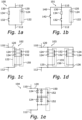
- a module for use in an energy storage system includes a first terminal and a second terminal, via which the module may be connected to e.g. one or more other modules and/or to an electrical power grid.
- the module further includes a supercapacitor branch, including an arrangement of one or more supercapacitors.
- the module further includes a resistive bypass branch including at least a first bypass switch and a resistance connected in series. In the module, the supercapacitor branch and the resistive bypass branch are connected in parallel between the first terminal and the second terminal.
- the term "supercapacitor” refers to a capacitor having a capacitance value higher than normal capacitors, but with lower voltage limits. Such a supercapacitor bridges a gap between normal (electrolytic) capacitors and rechargeable batteries.
- a supercapacitor may also be referred to as an “ultracapacitor” or “Electrochemical Double Layer Capacitor (EDLC)”.
- the bypass switch may be closed such that a remaining energy of the supercapacitor branch may be discharged/burned via the resistance.
- the fault may be cleared and operation of e.g. an energy storage system in which the module forms part may at least temporally continue to operate as intended.
- a supercapacitor branch 120 is connected between the first terminal 110 and the second terminal 112 and includes an arrangement 122 including at least one supercapacitor 124.
- an arrangement 122 including at least one supercapacitor 124 In the module 100, only a single supercapacitor 124 is illustrated in Figure 1a , but it is envisaged that the arrangement 122 may include also more than one supercapacitor. If that is the case, the supercapacitors 124 in the arrangement 122 in the supercapacitor branch 120 may be connected in series and/or in parallel as needed to meet specific voltage and/or current supply requirements.
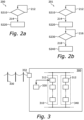
- the step S220 includes lowering a remaining energy in the (one or more) supercapacitors of the module by closing the first bypass switch within the resistive bypass branch.
- the supercapacitors may be discharged through the resistance of the resistive bypass branch, and the fault may thereby be handled without negatively affecting other modules within a same energy storage system.
- FIG. 3 schematically illustrates an energy storage system 300, including a plurality 310 of modules 312 connected in series.
- the system 300 also includes control means 320 (such as e.g. a computer implemented controller, or similar) for controlling at least one of the modules 312.
- control means 320 such as e.g. a computer implemented controller, or similar
- the system also 300 includes means necessary for e.g. detecting whether a fault has occurred within a module 312, and the control means 320 is thus such that the module 312 may be controlled in accordance with a method as described herein, for example any one of the methods 200 and 201 described above with reference to Figures 2a and 2b .
- the control means 320 may instead form part of a module 312, and i.e. that each module 312 may have its own internal control means 320.
- the system 300 may be connected e.g. to an electrical power grid 330, in order to provide stabilization of the electrical power grid 330 in times when e.g. a demand for power is high.
- the energy storage system may receive power from the grid 330 in order to charge the supercapacitors in the modules 312.
- the increased demand may be compensated for by the system 300 instead providing power to the grid 330 from the supercapacitors of the modules 312.
- the electrical power grid 330 is an AC power grid
- the connection to the electrical power grid 330 may be provided via an AC/DC conversion stage 332.
- an AC/DC conversion stage 332 may, for control purposes, also be connected to the control means 320.
- the system 300 may also include at least one further plurality 340 of series-connected modules (as e.g. described herein).
- the further plurality 340 may be connected in series with the plurality 310.
- the use of supercapacitors may enable a faster stabilization (due to the faster response time in terms of charging/discharging of the supercapacitors compared to e.g. traditional rechargeable batteries), and also an increased reliability as supercapacitors may handle an increased number of such charging/discharging cycles.
- the modules, control method therefor, as well as the energy storage system as described herein provide an improved reliability in that a fault (e.g. a short circuit) within a module may be properly handled, and the module even completely bypassed, such that the operation of the other modules are not negatively affected by the occurrence of such a fault, and such that the system as a whole may still be available thereafter.
- a fault e.g. a short circuit
- fault handling may be distributed within the energy storage system.
- one or more diodes as described in here provides further protection against negative voltages.
Landscapes
- Engineering & Computer Science (AREA)
- Power Engineering (AREA)
- Charge And Discharge Circuits For Batteries Or The Like (AREA)
- Protection Of Static Devices (AREA)
Claims (12)
- Modul (100) zur Verwendung in einem Energiespeichersystem, das beinhaltet:einen ersten Anschluss (110) und einen zweiten Anschluss (112);einen Superkondensatorzweig (120) einschließlich einer Anordnung (122) mit einem oder mehreren Superkondensatoren (124), undeinen Widerstandsbypasszweig (130) einschließlich zumindest eines ersten Bypassschalters (132) und eines Widerstands (134), die in Reihe verbunden sind,wobei der Superkonensatorzweig und der Widerstandsbypasszweig parallel zwischen dem ersten Anschluss und dem zweiten Anschluss verbunden sind;ferner einschließlich eines Direktbypasszweigs (140) einschließlich zumindest eines zweiten Bypassschalters (142), wobei der Direktbypasszweig auch parallel mit dem Superkondensatorzweig und dem Widerstandsbypasszweig verbunden ist, zwischen dem ersten Anschluss und dem zweiten Anschluss;dadurch gekennzeichnet, dass der Direktbypasszweig (140) nicht auf einen in Reihe verbundenen Widerstand angewiesen ist oder beinhaltet und dass der erste Bypassschalter dazu konfiguriert ist, bei einem Auftreten eines Fehlers, der mit dem einen oder den mehreren Superkondensatoren assoziiert ist, so geschlossen zu werden, dass der eine oder die mehreren Superkondensatoren durch den Widerstand entladen werden, wodurch eine Restenergie in dem einen oder den mehreren Superkondensatoren gesenkt wird;wobei der zweite Bypassschalter dazu konfiguriert ist, anschließend geschlossen zu werden, um den einen oder die mehreren Superkondensatoren bei einem Auftreten, dass die Restenergie in dem einen oder den mehreren Superkondensatoren unter einem gewissen Schwellenwert liegt, direkt zu umgehen.
- Modul nach Anspruch 1, wobei es keine Sicherung gibt, die in Reihe mit der Anordnung eines oder mehrerer Superkondensatoren und einem beliebigen des ersten Anschlusses und des zweiten Anschlusses verbunden ist.
- Modul nach einem der Ansprüche 1 bis 2, wobei es keinen Schalter oder Leistungsschalter gibt, der in Reihe mit der Anordnung eines oder mehrerer Superkondensatoren und einem beliebigen des ersten Anschlusses und des zweiten Anschlusses verbunden ist.
- Modul nach Anspruch 1, wobei es keine Sicherung, keinen Schalter oder Leistungsschalter gibt, die bzw. der in Reihe mit der Anordnung eines oder mehrerer Superkondensatoren und einem beliebigen des ersten Anschlusses und des zweiten Anschlusses verbunden ist.
- Modul nach einem der vorstehenden Ansprüche, wobei die Anordnung eines oder mehrerer Superkondensatoren direkt zwischen dem ersten Anschluss und dem zweiten Anschluss verbunden ist.
- Modul (102, 103, 104) nach einem der vorstehenden Ansprüche, ferner einschließlich eines Arrays (150) von Dioden (152), wobei jede Diode (152) in dem Array von Dioden umgekehrt über mindestens einen Superkondensator des einen oder der mehreren Superkondensatoren verbunden ist.
- Modul nach einem der vorstehenden Ansprüche, wobei die Anordnung eines oder mehrerer Superkondensatoren zwei oder mehr in Reihe verbundene Superkondensatoren beinhaltet.
- Modul nach einem der vorstehenden Ansprüche, wobei die Anordnung eines oder mehrerer Superkondensatoren zwei oder mehr parallel verbundene Superkondensatoren beinhaltet.
- Verfahren (200) zum Betreiben eines Moduls, das einen ersten Anschluss (110) und einen zweiten Anschluss (112), einen Superkondensatorzweig (120) einschließlich einer Anordnung (122) eines oder mehrerer Superkondensatoren (124) und einen Widerstandsbypasszweig (130) einschließlich zumindest eines ersten Bypassschalters (132) und eines Widerstands (134), die in Reihe verbunden sind, beinhaltet, wobei der Superkondensatorzweig und der Widerstandsbypasszweig parallel zwischen dem ersten Anschluss und dem zweiten Anschluss verbunden sind, wobei das Modul ferner einen Direktbypasszweig (140) einschließlich zumindest eines zweiten Bypassschalters (142), wobei der Direktbypasszweig nicht auf einen in Reihe verbundenen Widerstand angewiesen ist oder beinhaltet und auch parallel mit dem Superkondensatorzweig und dem Widerstandsbypasszweig verbunden ist, zwischen dem ersten Anschluss und dem zweiten Anschluss beinhaltet, wobei das Verfahren beinhaltet:a) Detektieren (S210) eines Auftretens eines Fehlers, der mit dem einen oder den mehreren Superkondensatoren assoziiert ist;b) Senken (S220) einer Restenergie in dem einen oder den mehreren Superkondensatoren durch Schließen des ersten Bypassschalters, wodurch der eine oder die mehreren Superkondensatoren durch den Widerstand entladen werden;c-i) Bestimmen (S230), ob die Restenergie in dem einen oder den mehreren Superkondensatoren unter einem gewissen Schwellenwert liegt, undc-ii) beim Bestimmen, dass die Restenergie unter dem gewissen Schwellenwert liegt, direktes Umgehen (S240) des einen oder der mehreren Superkondensatoren durch Schließen des zweiten Bypassschalters.
- Verfahren nach Anspruch 9, wobei der Fehler ein Kurzschluss über mindestens einen des einen oder der mehreren Superkondensatoren ist.
- Energiespeichersystem (300), das beinhaltet:eine Vielzahl (310) von Modulen (312) nach einem der Ansprüche 1 bis 8, die in Reihe verbunden sind;eine Steuerung und/oder ein internes Superkondensator-Diagnosemittel, die bzw. das dazu konfiguriert ist, ein Auftreten eines Fehlers zu detektieren, der mit dem einen oder den mehreren Superkondensatoren mindestens eines Moduls der Vielzahl von Modulen assoziiert ist;ein Steuermittel, das dazu ausgelegt ist, für das mindestens eine Modul der Vielzahl von Modulen, den ersten Bypassschalter zu schließen, wodurch der eine oder die mehreren Superkondensatoren durch den Widerstand entladen werden, wodurch eine Restenergie in dem einen oder den mehreren Superkondensatoren gesenkt wird;ein Mittel, das dazu konfiguriert ist, für das mindestens eine Modul der Vielzahl von Modulen, zu bestimmen, ob die Restenergie in dem einen oder den mehreren Superkondensatoren unter einem gewissen Schwellenwert liegt,wobei das Steuermittel ferner dazu konfiguriert ist, für das mindestens eine Modul der Vielzahl von Modulen, den zweiten Bypassschalter bei der Bestimmung zu schließen, dass die Restenergie unter dem gewissen Schwellenwert liegt, wodurch der eine oder die mehreren Superkondensatoren direkt umgangen werden.
- Energiespeichersystem (301) nach Anspruch 11, das ferner zumindest eine zweite Vielzahl (340) von Modulen (312) nach einem der Ansprüche 1 bis 8 beinhaltet, die in Reihe verbunden sind, wobei die erste Vielzahl von Modulen und die zumindest eine zweite Vielzahl von Modulen parallel verbunden sind.
Applications Claiming Priority (1)
| Application Number | Priority Date | Filing Date | Title |
|---|---|---|---|
| PCT/EP2021/064573 WO2022253407A1 (en) | 2021-05-31 | 2021-05-31 | Module for large scale energy storage |
Publications (2)
| Publication Number | Publication Date |
|---|---|
| EP4348795A1 EP4348795A1 (de) | 2024-04-10 |
| EP4348795B1 true EP4348795B1 (de) | 2025-07-02 |
Family
ID=76325503
Family Applications (1)
| Application Number | Title | Priority Date | Filing Date |
|---|---|---|---|
| EP21730837.8A Active EP4348795B1 (de) | 2021-05-31 | 2021-05-31 | Modul zur grossraum-energiespeicherung |
Country Status (5)
| Country | Link |
|---|---|
| US (1) | US12249856B2 (de) |
| EP (1) | EP4348795B1 (de) |
| JP (1) | JP7675217B2 (de) |
| CN (1) | CN117441278A (de) |
| WO (1) | WO2022253407A1 (de) |
Families Citing this family (3)
| Publication number | Priority date | Publication date | Assignee | Title |
|---|---|---|---|---|
| WO2024200298A1 (en) * | 2023-03-24 | 2024-10-03 | Hitachi Energy Ltd | Electrical protection circuit for energy storage unit |
| EP4525258A1 (de) * | 2023-09-13 | 2025-03-19 | Hitachi Energy Ltd | Koordinierte auslösung des schutzes und bypass auf modulebene in energiespeichersystemen |
| CN119297973B (zh) * | 2024-09-10 | 2025-10-03 | 中国电建集团福建省电力勘测设计院有限公司 | 一种基于超级电容的直流耗能装置 |
Citations (4)
| Publication number | Priority date | Publication date | Assignee | Title |
|---|---|---|---|---|
| US20090066291A1 (en) | 2007-09-10 | 2009-03-12 | Jenn-Yang Tien | Distributed energy storage control system |
| US20130009600A1 (en) | 2011-07-08 | 2013-01-10 | Samsung Electro-Mechanics Co., Ltd | Electric energy storage apparatus, voltage equalization module and voltage equalization method |
| WO2016044931A1 (en) | 2014-09-22 | 2016-03-31 | Polyvalor, Limited Partnership | Energy storage device and modular circuit |
| WO2020082660A1 (zh) | 2018-10-22 | 2020-04-30 | 南京南瑞继保电气有限公司 | 一种直流耗能装置及其控制方法 |
Family Cites Families (22)
| Publication number | Priority date | Publication date | Assignee | Title |
|---|---|---|---|---|
| JPH0799142A (ja) | 1993-09-28 | 1995-04-11 | Okamura Kenkyusho:Kk | 電力用蓄電装置 |
| US5545933A (en) * | 1993-09-28 | 1996-08-13 | Okamura Laboratory Inc. | Electric power storage apparatus |
| US7471068B2 (en) | 2006-11-03 | 2008-12-30 | Ivus Industries, Llc | Ultra-fast ultracapacitor charging method and charger |
| CN101217078B (zh) | 2008-01-04 | 2011-06-01 | 西安交通大学 | 一种带串联电阻的永磁机构真空断路器组合装置 |
| CN201153087Y (zh) | 2008-01-04 | 2008-11-19 | 西安交通大学 | 一种带串联电阻的永磁机构真空断路器组合装置 |
| DE102009025211A1 (de) | 2009-06-16 | 2010-01-28 | Daimler Ag | Batteriezellenanordnung mit vermindertem Ausfallrisiko |
| EP2596564B1 (de) | 2010-07-23 | 2014-03-19 | ABB Technology AG | Verfahren und anordnung für den schutz einer kondensatorbank |
| KR101158214B1 (ko) * | 2010-09-27 | 2012-06-19 | 삼성전기주식회사 | 에너지 저장체의 전압 안정화 장치 및 그 방법 |
| US10536007B2 (en) | 2011-03-05 | 2020-01-14 | Powin Energy Corporation | Battery energy storage system and control system and applications thereof |
| US9559529B1 (en) | 2011-07-28 | 2017-01-31 | The United States Of America As Represented By The Administrator Of National Aeronautics And Space Administration | Modular battery controller |
| CN104956565B (zh) | 2012-12-24 | 2019-05-07 | 麦格纳覆盖件有限公司 | 用于汽车系统的备用能量源及相关控制方法 |
| US20150092311A1 (en) | 2013-09-30 | 2015-04-02 | Abb Technology Ag | Methods, systems, and computer readable media for protection of direct current building electrical systems |
| US9525290B2 (en) | 2013-10-25 | 2016-12-20 | Saft | Bypassable battery modules |
| EP3158619A4 (de) | 2014-06-20 | 2018-03-07 | Ioxus, Inc. | Motorstart und batterieträgermodul |
| CN105991054A (zh) | 2015-03-06 | 2016-10-05 | 南京南瑞继保电气有限公司 | 一种换流器子模块、控制方法及换流器 |
| US10050252B2 (en) | 2015-04-17 | 2018-08-14 | The Boeing Company | Fault tolerant battery cell bypass device and system |
| JP6226408B2 (ja) | 2015-06-22 | 2017-11-08 | 株式会社東芝 | 蓄電池システム、蓄電池モジュール及び蓄電池システム運用方法 |
| CN106229956A (zh) | 2016-09-27 | 2016-12-14 | 上海北堃电力科技有限公司 | 一种电容器保护设备及串联补偿装置 |
| US11168663B2 (en) | 2017-06-22 | 2021-11-09 | General Electric Company | Blade pitch system including power source for wind turbine |
| CN108322056B (zh) | 2018-03-23 | 2020-03-20 | 南京南瑞继保电气有限公司 | 一种模块化高压直流变换装置及其控制方法 |
| CN109860741A (zh) | 2019-02-27 | 2019-06-07 | 广州宝狮新能源有限公司 | 一种可兼容容错的大型电池串联与pcs并联系统 |
| KR102127888B1 (ko) | 2019-10-08 | 2020-06-29 | 주식회사 엠알티 | 다중 입력 지락 및 단락 차단 스위치를 적용한 에너지저장장치 |
-
2021
- 2021-05-31 US US18/565,973 patent/US12249856B2/en active Active
- 2021-05-31 EP EP21730837.8A patent/EP4348795B1/de active Active
- 2021-05-31 CN CN202180098900.2A patent/CN117441278A/zh active Pending
- 2021-05-31 JP JP2023573624A patent/JP7675217B2/ja active Active
- 2021-05-31 WO PCT/EP2021/064573 patent/WO2022253407A1/en not_active Ceased
Patent Citations (4)
| Publication number | Priority date | Publication date | Assignee | Title |
|---|---|---|---|---|
| US20090066291A1 (en) | 2007-09-10 | 2009-03-12 | Jenn-Yang Tien | Distributed energy storage control system |
| US20130009600A1 (en) | 2011-07-08 | 2013-01-10 | Samsung Electro-Mechanics Co., Ltd | Electric energy storage apparatus, voltage equalization module and voltage equalization method |
| WO2016044931A1 (en) | 2014-09-22 | 2016-03-31 | Polyvalor, Limited Partnership | Energy storage device and modular circuit |
| WO2020082660A1 (zh) | 2018-10-22 | 2020-04-30 | 南京南瑞继保电气有限公司 | 一种直流耗能装置及其控制方法 |
Non-Patent Citations (1)
| Title |
|---|
| MARIN S. HALPER, JAMES C. ELLENBOGEN: "Supercapacitors: A Brief Overview", TECHNICAL REVIEW, MITRE, MCLEAN, VIRGINIA, USA, 1 March 2006 (2006-03-01), McLean, Virginia, USA, pages 1 - 40, XP009566260 |
Also Published As
| Publication number | Publication date |
|---|---|
| WO2022253407A1 (en) | 2022-12-08 |
| CN117441278A (zh) | 2024-01-23 |
| US20240266847A1 (en) | 2024-08-08 |
| JP2024519185A (ja) | 2024-05-08 |
| US12249856B2 (en) | 2025-03-11 |
| EP4348795A1 (de) | 2024-04-10 |
| JP7675217B2 (ja) | 2025-05-12 |
Similar Documents
| Publication | Publication Date | Title |
|---|---|---|
| EP4348795B1 (de) | Modul zur grossraum-energiespeicherung | |
| KR101483129B1 (ko) | 배터리 시스템 및 에너지 저장 시스템 | |
| CN103733381A (zh) | 保护电池组的元件 | |
| JP6811019B2 (ja) | 二次電池システム | |
| CN105164545A (zh) | 蓄电装置的异常检测电路及具备该电路的蓄电装置 | |
| US10367187B2 (en) | Storage battery including a disconnector having a fuse and an explosive with a heat bridge providing continuity of service in the event of a malfunction | |
| CN211830332U (zh) | 用于提升蓄电池组可用性的辅助电源装置 | |
| US6741437B2 (en) | Safety device for electrical storage cell battery and battery equipped with the device | |
| JP4057193B2 (ja) | 電池並列使用時の異常検出方法 | |
| JP2016134962A (ja) | 蓄電システム | |
| KR102848533B1 (ko) | 배터리 상태 검출 장치 및 배터리 보호 장치 | |
| US8743521B2 (en) | Photovoltaic system with overvoltage protection | |
| JP6155854B2 (ja) | 電池システム | |
| CN113904307A (zh) | 直流母线电容缓冲保护电路及方法 | |
| JP2002159135A (ja) | 電気二重層コンデンサモジュール用保護回路 | |
| CN216312666U (zh) | 直流母线电容缓冲保护电路 | |
| CN111342548A (zh) | 一种用于提升蓄电池组可用性的辅助电源装置 | |
| JP2018011447A (ja) | 大容量蓄電池システム | |
| US20250141244A1 (en) | Discharge resistor arrangement for energy storage cabinets in an energy storage system | |
| JP2011160639A (ja) | 瞬低対策装置 | |
| KR20250177387A (ko) | 고전압 dc 에너지 관리 시스템을 위한 바이패스 기능을 갖는 에너지 저장 회로 | |
| JP5962558B2 (ja) | 電池監視装置 | |
| EP4607744A1 (de) | Energiespeichersystem und verfahren zum betreiben einer schutzschaltung in einem energiespeichersystem | |
| EP4415206A1 (de) | Energiespeichersegment für ein energiespeichersystem und verfahren zur steuerung eines energiespeichersystems | |
| US20250260245A1 (en) | Battery string pre-charge operation |
Legal Events
| Date | Code | Title | Description |
|---|---|---|---|
| STAA | Information on the status of an ep patent application or granted ep patent |
Free format text: STATUS: UNKNOWN |
|
| STAA | Information on the status of an ep patent application or granted ep patent |
Free format text: STATUS: THE INTERNATIONAL PUBLICATION HAS BEEN MADE |
|
| PUAI | Public reference made under article 153(3) epc to a published international application that has entered the european phase |
Free format text: ORIGINAL CODE: 0009012 |
|
| STAA | Information on the status of an ep patent application or granted ep patent |
Free format text: STATUS: REQUEST FOR EXAMINATION WAS MADE |
|
| 17P | Request for examination filed |
Effective date: 20231102 |
|
| AK | Designated contracting states |
Kind code of ref document: A1 Designated state(s): AL AT BE BG CH CY CZ DE DK EE ES FI FR GB GR HR HU IE IS IT LI LT LU LV MC MK MT NL NO PL PT RO RS SE SI SK SM TR |
|
| DAV | Request for validation of the european patent (deleted) | ||
| DAX | Request for extension of the european patent (deleted) | ||
| RIN1 | Information on inventor provided before grant (corrected) |
Inventor name: SOONG, THEODORE Inventor name: WU, TONG Inventor name: BAI, HAOFENG Inventor name: MENG, LEXUAN Inventor name: SVENSSON, JAN Inventor name: INGESTROEM, GUNNAR Inventor name: STEINKE, JUERGEN Inventor name: HASLER, JEAN-PHILIPPE |
|
| GRAP | Despatch of communication of intention to grant a patent |
Free format text: ORIGINAL CODE: EPIDOSNIGR1 |
|
| STAA | Information on the status of an ep patent application or granted ep patent |
Free format text: STATUS: GRANT OF PATENT IS INTENDED |
|
| INTG | Intention to grant announced |
Effective date: 20250121 |
|
| GRAS | Grant fee paid |
Free format text: ORIGINAL CODE: EPIDOSNIGR3 |
|
| P01 | Opt-out of the competence of the unified patent court (upc) registered |
Free format text: CASE NUMBER: APP_17847/2025 Effective date: 20250411 |
|
| GRAA | (expected) grant |
Free format text: ORIGINAL CODE: 0009210 |
|
| STAA | Information on the status of an ep patent application or granted ep patent |
Free format text: STATUS: THE PATENT HAS BEEN GRANTED |
|
| RIN1 | Information on inventor provided before grant (corrected) |
Inventor name: SOONG, THEODORE Inventor name: WU, TONG Inventor name: BAI, HAOFENG Inventor name: MENG, LEXUAN Inventor name: SVENSSON, JAN Inventor name: INGESTROEM, GUNNAR Inventor name: STEINKE, JUERGEN Inventor name: HASLER, JEAN-PHILIPPE |
|
| AK | Designated contracting states |
Kind code of ref document: B1 Designated state(s): AL AT BE BG CH CY CZ DE DK EE ES FI FR GB GR HR HU IE IS IT LI LT LU LV MC MK MT NL NO PL PT RO RS SE SI SK SM TR |
|
| REG | Reference to a national code |
Ref country code: GB Ref legal event code: FG4D |
|
| REG | Reference to a national code |
Ref country code: CH Ref legal event code: EP |
|
| REG | Reference to a national code |
Ref country code: DE Ref legal event code: R096 Ref document number: 602021033366 Country of ref document: DE |
|
| REG | Reference to a national code |
Ref country code: IE Ref legal event code: FG4D |
|
| REG | Reference to a national code |
Ref country code: NL Ref legal event code: MP Effective date: 20250702 |
|
| PG25 | Lapsed in a contracting state [announced via postgrant information from national office to epo] |
Ref country code: PT Free format text: LAPSE BECAUSE OF FAILURE TO SUBMIT A TRANSLATION OF THE DESCRIPTION OR TO PAY THE FEE WITHIN THE PRESCRIBED TIME-LIMIT Effective date: 20251103 |
|
| PG25 | Lapsed in a contracting state [announced via postgrant information from national office to epo] |
Ref country code: NL Free format text: LAPSE BECAUSE OF FAILURE TO SUBMIT A TRANSLATION OF THE DESCRIPTION OR TO PAY THE FEE WITHIN THE PRESCRIBED TIME-LIMIT Effective date: 20250702 |
|
| REG | Reference to a national code |
Ref country code: AT Ref legal event code: MK05 Ref document number: 1810391 Country of ref document: AT Kind code of ref document: T Effective date: 20250702 |
|
| PG25 | Lapsed in a contracting state [announced via postgrant information from national office to epo] |
Ref country code: IS Free format text: LAPSE BECAUSE OF FAILURE TO SUBMIT A TRANSLATION OF THE DESCRIPTION OR TO PAY THE FEE WITHIN THE PRESCRIBED TIME-LIMIT Effective date: 20251102 |
|
| PG25 | Lapsed in a contracting state [announced via postgrant information from national office to epo] |
Ref country code: NO Free format text: LAPSE BECAUSE OF FAILURE TO SUBMIT A TRANSLATION OF THE DESCRIPTION OR TO PAY THE FEE WITHIN THE PRESCRIBED TIME-LIMIT Effective date: 20251002 |
|
| REG | Reference to a national code |
Ref country code: LT Ref legal event code: MG9D |
|
| PG25 | Lapsed in a contracting state [announced via postgrant information from national office to epo] |
Ref country code: AT Free format text: LAPSE BECAUSE OF FAILURE TO SUBMIT A TRANSLATION OF THE DESCRIPTION OR TO PAY THE FEE WITHIN THE PRESCRIBED TIME-LIMIT Effective date: 20250702 |
|
| PG25 | Lapsed in a contracting state [announced via postgrant information from national office to epo] |
Ref country code: FI Free format text: LAPSE BECAUSE OF FAILURE TO SUBMIT A TRANSLATION OF THE DESCRIPTION OR TO PAY THE FEE WITHIN THE PRESCRIBED TIME-LIMIT Effective date: 20250702 |
|
| PG25 | Lapsed in a contracting state [announced via postgrant information from national office to epo] |
Ref country code: HR Free format text: LAPSE BECAUSE OF FAILURE TO SUBMIT A TRANSLATION OF THE DESCRIPTION OR TO PAY THE FEE WITHIN THE PRESCRIBED TIME-LIMIT Effective date: 20250702 |
|
| PG25 | Lapsed in a contracting state [announced via postgrant information from national office to epo] |
Ref country code: GR Free format text: LAPSE BECAUSE OF FAILURE TO SUBMIT A TRANSLATION OF THE DESCRIPTION OR TO PAY THE FEE WITHIN THE PRESCRIBED TIME-LIMIT Effective date: 20251003 |
|
| PG25 | Lapsed in a contracting state [announced via postgrant information from national office to epo] |
Ref country code: CZ Free format text: LAPSE BECAUSE OF FAILURE TO SUBMIT A TRANSLATION OF THE DESCRIPTION OR TO PAY THE FEE WITHIN THE PRESCRIBED TIME-LIMIT Effective date: 20250702 Ref country code: SE Free format text: LAPSE BECAUSE OF FAILURE TO SUBMIT A TRANSLATION OF THE DESCRIPTION OR TO PAY THE FEE WITHIN THE PRESCRIBED TIME-LIMIT Effective date: 20250702 |
|
| PG25 | Lapsed in a contracting state [announced via postgrant information from national office to epo] |
Ref country code: LV Free format text: LAPSE BECAUSE OF FAILURE TO SUBMIT A TRANSLATION OF THE DESCRIPTION OR TO PAY THE FEE WITHIN THE PRESCRIBED TIME-LIMIT Effective date: 20250702 |
|
| PG25 | Lapsed in a contracting state [announced via postgrant information from national office to epo] |
Ref country code: PL Free format text: LAPSE BECAUSE OF FAILURE TO SUBMIT A TRANSLATION OF THE DESCRIPTION OR TO PAY THE FEE WITHIN THE PRESCRIBED TIME-LIMIT Effective date: 20250702 Ref country code: BG Free format text: LAPSE BECAUSE OF FAILURE TO SUBMIT A TRANSLATION OF THE DESCRIPTION OR TO PAY THE FEE WITHIN THE PRESCRIBED TIME-LIMIT Effective date: 20250702 |
|
| PG25 | Lapsed in a contracting state [announced via postgrant information from national office to epo] |
Ref country code: RS Free format text: LAPSE BECAUSE OF FAILURE TO SUBMIT A TRANSLATION OF THE DESCRIPTION OR TO PAY THE FEE WITHIN THE PRESCRIBED TIME-LIMIT Effective date: 20251002 |
|
| PG25 | Lapsed in a contracting state [announced via postgrant information from national office to epo] |
Ref country code: ES Free format text: LAPSE BECAUSE OF FAILURE TO SUBMIT A TRANSLATION OF THE DESCRIPTION OR TO PAY THE FEE WITHIN THE PRESCRIBED TIME-LIMIT Effective date: 20250702 |
|
| REG | Reference to a national code |
Ref country code: DE Ref legal event code: R026 Ref document number: 602021033366 Country of ref document: DE |
|
| PLBI | Opposition filed |
Free format text: ORIGINAL CODE: 0009260 |
|
| PG25 | Lapsed in a contracting state [announced via postgrant information from national office to epo] |
Ref country code: SM Free format text: LAPSE BECAUSE OF FAILURE TO SUBMIT A TRANSLATION OF THE DESCRIPTION OR TO PAY THE FEE WITHIN THE PRESCRIBED TIME-LIMIT Effective date: 20250702 |
|
| REG | Reference to a national code |
Ref country code: CH Ref legal event code: L11 Free format text: ST27 STATUS EVENT CODE: U-0-0-L10-L11 (AS PROVIDED BY THE NATIONAL OFFICE) Effective date: 20260409 |
|
| PLAB | Opposition data, opponent's data or that of the opponent's representative modified |
Free format text: ORIGINAL CODE: 0009299OPPO |
|
| PG25 | Lapsed in a contracting state [announced via postgrant information from national office to epo] |
Ref country code: DK Free format text: LAPSE BECAUSE OF FAILURE TO SUBMIT A TRANSLATION OF THE DESCRIPTION OR TO PAY THE FEE WITHIN THE PRESCRIBED TIME-LIMIT Effective date: 20250702 |
|
| PG25 | Lapsed in a contracting state [announced via postgrant information from national office to epo] |
Ref country code: IT Free format text: LAPSE BECAUSE OF FAILURE TO SUBMIT A TRANSLATION OF THE DESCRIPTION OR TO PAY THE FEE WITHIN THE PRESCRIBED TIME-LIMIT Effective date: 20250702 |
|
| REG | Reference to a national code |
Ref country code: CH Ref legal event code: L10 Free format text: ST27 STATUS EVENT CODE: U-0-0-L10-L00 (AS PROVIDED BY THE NATIONAL OFFICE) Effective date: 20260416 |
|
| PLAX | Notice of opposition and request to file observation + time limit sent |
Free format text: ORIGINAL CODE: EPIDOSNOBS2 |