EP4347315B1 - System zur befestigung eines elektrisch betriebenen geräts im innenraum eines kraftfahrzeugs - Google Patents
System zur befestigung eines elektrisch betriebenen geräts im innenraum eines kraftfahrzeugs Download PDFInfo
- Publication number
- EP4347315B1 EP4347315B1 EP22724470.4A EP22724470A EP4347315B1 EP 4347315 B1 EP4347315 B1 EP 4347315B1 EP 22724470 A EP22724470 A EP 22724470A EP 4347315 B1 EP4347315 B1 EP 4347315B1
- Authority
- EP
- European Patent Office
- Prior art keywords
- fixing
- rail
- adapter module
- movable contact
- movable
- Prior art date
- Legal status (The legal status is an assumption and is not a legal conclusion. Google has not performed a legal analysis and makes no representation as to the accuracy of the status listed.)
- Active
Links
Images


Classifications
-
- B—PERFORMING OPERATIONS; TRANSPORTING
- B60—VEHICLES IN GENERAL
- B60R—VEHICLES, VEHICLE FITTINGS, OR VEHICLE PARTS, NOT OTHERWISE PROVIDED FOR
- B60R11/00—Arrangements for holding or mounting articles, not otherwise provided for
- B60R11/02—Arrangements for holding or mounting articles, not otherwise provided for for radio sets, television sets, telephones, or the like; Arrangement of controls thereof
-
- B—PERFORMING OPERATIONS; TRANSPORTING
- B60—VEHICLES IN GENERAL
- B60R—VEHICLES, VEHICLE FITTINGS, OR VEHICLE PARTS, NOT OTHERWISE PROVIDED FOR
- B60R11/00—Arrangements for holding or mounting articles, not otherwise provided for
- B60R2011/0001—Arrangements for holding or mounting articles, not otherwise provided for characterised by position
- B60R2011/0003—Arrangements for holding or mounting articles, not otherwise provided for characterised by position inside the vehicle
- B60R2011/0005—Dashboard
-
- B—PERFORMING OPERATIONS; TRANSPORTING
- B60—VEHICLES IN GENERAL
- B60R—VEHICLES, VEHICLE FITTINGS, OR VEHICLE PARTS, NOT OTHERWISE PROVIDED FOR
- B60R11/00—Arrangements for holding or mounting articles, not otherwise provided for
- B60R2011/0042—Arrangements for holding or mounting articles, not otherwise provided for characterised by mounting means
- B60R2011/0049—Arrangements for holding or mounting articles, not otherwise provided for characterised by mounting means for non integrated articles
- B60R2011/005—Connection with the vehicle part
- B60R2011/0061—Connection with the vehicle part using key-type connections
-
- B—PERFORMING OPERATIONS; TRANSPORTING
- B60—VEHICLES IN GENERAL
- B60R—VEHICLES, VEHICLE FITTINGS, OR VEHICLE PARTS, NOT OTHERWISE PROVIDED FOR
- B60R11/00—Arrangements for holding or mounting articles, not otherwise provided for
- B60R2011/0042—Arrangements for holding or mounting articles, not otherwise provided for characterised by mounting means
- B60R2011/008—Adjustable or movable supports
- B60R2011/0084—Adjustable or movable supports with adjustment by linear movement in their operational position
-
- B—PERFORMING OPERATIONS; TRANSPORTING
- B60—VEHICLES IN GENERAL
- B60R—VEHICLES, VEHICLE FITTINGS, OR VEHICLE PARTS, NOT OTHERWISE PROVIDED FOR
- B60R11/00—Arrangements for holding or mounting articles, not otherwise provided for
- B60R11/02—Arrangements for holding or mounting articles, not otherwise provided for for radio sets, television sets, telephones, or the like; Arrangement of controls thereof
- B60R2011/0294—Apparatus with multi-functionalities, e.g. radio and telephone
Definitions
- the invention relates to the field of motor vehicle equipment, and more specifically concerns the fixing to a motor vehicle dashboard of various elements which must be electrically powered, such as an electrical outlet, a telephone charger, a refrigerated cup holder, etc.
- the invention is based on the observation that it is now necessary to offer the occupants of a motor vehicle flexibility and ease in the use of various portable or mobile accessories that they have and which require an electrical power supply.
- the invention thus aims to propose a fixing system allowing the fixing of accessories and modules which must be electrically powered.
- the fixing system according to the invention offers vehicle occupants great flexibility for fixing one or more accessories that must be both fixed and electrically connected, such as an electrical outlet, a portable electronic device charger, etc.
- the fixing to the fixing rail and the electrical connection are carried out by means of the same elements, namely the movable contacts, the invention makes it possible to fix and electrically connect an accessory simply and quickly.
- the conductors of the fixing rail are arranged within cavities open towards the rear, the conductors are difficult to access and are protected.
- the system according to the invention thus has a very high level of safety.
- each movable contact is movable in translation relative to the body along a first axis and along a second axis, the first and second axes being intersecting and preferably perpendicular, such that the movable contacts are movable along the first axis between an advanced position and a retracted position, and are movable along the second axis between a low position and a high position, the high and advanced position of the movable contacts corresponding to the engagement position, the low and retracted position of the movable contacts corresponding to the fixing position.
- each movable contact is secured to a respective plate, each plate sliding in a respective groove provided in the body of the adapter module.
- each movable contact is mounted in translation on the corresponding plate, each plate comprising a barrel sliding in a housing of complementary shape provided in the corresponding movable contact.
- the barrel of each plate comprises an elastic return device, such as a spring, urging the movable contact towards its high position.
- each movable contact comprises an end portion, the end portion being, in the fixing position of the movable contact, housed in a cavity of complementary shape provided in the body of the adapter module.
- each movable contact comprises an internal conductor, electrically connected to the contact face of the front part of the movable contact on the one hand, and to a contact face of a rear part of the movable contact on the other hand.
- each internal conductor of the body is electrically connected to a respective terminal.
- the invention also relates to a motor vehicle comprising a fixing system conforming to that defined above, the fixing rail being fixed in a vehicle interior trim element, such as a dashboard, a door panel or a console, the conductors of the fixing rail being connected to an on-board electrical network of the vehicle.
- a vehicle interior trim element such as a dashboard, a door panel or a console
- FIG. 1 partially represents a passenger compartment of a motor vehicle 1.
- the vehicle 1 comprises a dashboard 10.
- the dashboard 10 is equipped with a fixing system 2 according to the invention, making it possible to simultaneously fix, on a fixing rail 3, one or more adapter modules 4, such as an adapter module forming an electrical socket for powering a portable or nomadic electronic device, such as a laptop computer.
- a fixing system 2 according to the invention, making it possible to simultaneously fix, on a fixing rail 3, one or more adapter modules 4, such as an adapter module forming an electrical socket for powering a portable or nomadic electronic device, such as a laptop computer.
- FIG. 2 is a perspective view of the adapter module 4 of the Figure 1 coupled to the fixing rail 3, of which only a section is shown.
- the adapter module 4 is in this configuration both fixed and electrically connected to the fixing rail 3.
- the fixing rail 3 has an elongated shape. It comprises a rear face intended to be fixed to a motor vehicle trim element, such as the dashboard 10 of the Figure 1 , and a front face, intended to receive one or more adapter modules such as the adapter module 4 of the figures.
- the adapter module 4 comprises a body 40.
- the body 40 comprises a first part, or fixing part 40a and a second part, or functional part 40b, the functional part 40b forming in the example of the figures an electrical socket base.
- the fixing part 40a of the body 40 comprises a tab 42, making it possible to ensure the positioning of the adapter module on the fixing rail 3, the latter comprising on its front face a positioning groove 30 configured to receive the tab 42.
- the adapter module 4 When the adapter module 4 is fixed to the fixing rail 3, the adapter module is retained by means of two movable contacts 44, namely a lower movable contact and an upper movable contact. Each of these movable contacts 44 also provides the electrical connection between the fixing rail 3 and the adapter module 4. Each movable contact 44 is movable between an engagement position, allowing the engagement and disengagement of the adapter module with the fixing rail 3, and a fixing position, ensuring the fixing of the adapter module 4 on the fixing rail 3, as well as an electrical connection between these two elements.
- each movable contact 44 has a hook-shaped front portion 440, configured to be, in the fixing position of the movable contact 44, engaged with a respective rim 32 of the fixing rail 3.
- the fixing rail 3 thus comprises a rim 32 at an upper end 30a and a rim 32 at a lower end 30b.
- Each rim 32 comprises a return 320, so as to delimit a cavity 322 open towards the rear of the fixing rail.
- Each cavity 322 accommodates a respective electrical conductor 36, 38, arranged at the bottom of the corresponding cavity.
- each movable contact 44 constitutes the end of a return 444, and comprises a contact face (front) electrically connected to an internal conductor 446 integrated into the movable contact 44.
- the internal conductor 446 is arranged so as to connect the front part 440 of the movable contact 44 corresponding to a rear part 448 opposite the front part 440.
- the conductor 426 is electrically connected to a contact face (rear).
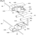
- the contact face of the rear part (448) is, as seen in particular on the figure 8 , electrically connected to one of two internal conductors 46, 48 arranged within the body 40, when the movable contact 44 is in the fixing position.
- each internal conductor 46, 48 is respectively electrically connected to one of two electrical terminals 50, 52.
- Each internal conductor 46, 48 comprises for this purpose a contact part 460, 480 forming a flexible strip and configured to come into contact with the connecting conductor 426 when the corresponding movable contact 44 is in the fixing position.
- Each movable contact is movable in translation relative to the body 40, along a first axis perpendicular to the surface of the fixing rail 3 when the adapter module 40 is attached to it, between an advanced position, visible on the figures 3 And 4 , and a withdrawn position, visible on the figures 2 And 6 .
- each movable contact 44 is in the example secured to a respective plate 54 mounted in translation in the body 40 of the adapter module 4, and sliding in an internal groove 56 formed in the body 40, in the example a T-shaped groove.
- each plate 54 comprises in the lower part a tongue 540 of adapted shape, for example of complementary shape to the internal groove 56.
- Each movable contact 44 is furthermore movable in translation relative to the body 40 along a second axis perpendicular to the first axis and perpendicular to the axis of elongation of the fixing rail 30. Each movable contact 44 is thus movable between a low position, visible on the figures 2 , 5 , And 6 , and a high position, visible on the figures 3 And 4 .
- each movable contact is mounted in translation on the corresponding plate 54.
- each plate 54 comprises a barrel 542 sliding in a complementary shaped housing 452 formed in the corresponding movable contact 44.
- each plate 54 accommodates an elastic return device, such as a spring 544, urging the corresponding movable contact 44 towards its high position.
- an elastic return device such as a spring 544, urging the corresponding movable contact 44 towards its high position.
- the high and forward position of the movable contacts 44 corresponds to the engagement position, while the low and retracted position of the movable contacts 44 corresponds to the fixing position.
- the movable contacts 44 are in their engagement position, i.e. their high and advanced position. In this position, the spacing between the front parts 440 (and more precisely between the returns 444) of the two movable contacts 44 is greater than the spacing between the edges 32 of the fixing rail 3 (and more precisely between the returns 320).
- this configuration makes it possible, during a first step, to bring the adapter module 4 closer to the fixing rail 3 and to insert the tab 42 of the body 40 into the groove 30 of the fixing rail 3, so that the front parts 440 of the two movable contacts 44 are arranged on either side of the fixing rail 30, and in particular behind the edges 32 and the returns 320.
- the movable contacts 44 are moved again, so that they move from their advanced (and low) position to their retracted position, or fixing position.
- This final movement has the effect of interlocking the front part 440 of each movable contact 44 with the corresponding edge 32, thus allowing the adapter module 4 to be fixed to the rail of fixing.
- the free end 442 of the front part 440 of each movable contact 44 is in contact with the corresponding conductor 36, 38 of the fixing rail 3, which has the effect of electrically connecting each of these conductors 36, 38 to the corresponding internal conductor 446, as visible in the figure 8 .
- each movable contact 44 comprises an end portion 454 configured to be housed in a cavity 58 of complementary shape provided in the body 40 when the corresponding movable contact 44 is in its fixing position, as visible in the Figure 6
- This configuration makes it possible to ensure locking of the movable contacts 44 in the fixing position, under the antagonistic action of the spring 544 on the one hand (which forces the corresponding movable contact 44 towards its high position) and the cavity 58 and the rim 320 on the other hand.
- the steps described above will be reversed.
- the first step will consist of moving the movable contacts from their fixing position to their low and forward position ( Figure 5 ), knowing that in this position, the action of the springs 544 will have the effect of automatically moving the movable contacts to their advanced and high position, position in which the adapter module 4 can be removed from the fixing rail 3.
- the fixing system described above makes it possible to easily and simply ensure the fixing and electrical connection of an adapter module to the fixing rail.
- the electrical contacts 36, 38 of the fixing rail 3 are concealed by the edges 32, and thus arranged at the bottom of a cavity oriented towards the rear of the rail, these conductors are made difficult to access by a user.
- the cavities 322 will be configured so that their dimensions do not allow a user to insert a finger therein. The system according to the invention therefore has both great flexibility and great ease of use, while ensuring a high degree of safety for users.
Landscapes
- Engineering & Computer Science (AREA)
- Mechanical Engineering (AREA)
- Details Of Connecting Devices For Male And Female Coupling (AREA)
- Fittings On The Vehicle Exterior For Carrying Loads, And Devices For Holding Or Mounting Articles (AREA)
- Switch Cases, Indication, And Locking (AREA)
Claims (10)
- Befestigungssystem (2) zur Befestigung eines Adaptermoduls im Fahrgastraum eines Kraftfahrzeugs (1). Das Befestigungssystem (2) umfasst:- eine längliche Befestigungsschiene (3) zur Befestigung an einem Verkleidungselement eines Kraftfahrzeugs (1), beispielsweise einem Armaturenbrett (10), wobei die Befestigungsschiene (3) eine Vorderseite zur Aufnahme eines Adaptermoduls (4) aufweist und zwei elektrische Leiter (36, 38) aufweist, die jeweils an einem oberen Ende (30a) und einem unteren Ende (30b) der Befestigungsschiene (3) angeordnet sind. Jeder Leiter (36, 38) befindet sich am Boden eines Hohlraums (322), der in einem entsprechenden Rand (32) der Befestigungsschiene (3) ausgebildet und zur Rückseite der Befestigungsschiene (3) hin offen ist,- mindestens ein Adaptermodul (4), wobei das Adaptermodul (4) so konfiguriert ist, dass es abnehmbar an der Befestigungsschiene (3) befestigt werden kann. Das Adaptermodul (4) umfasst einen Körper (40) und zwei bewegliche Kontakte (44), die relativ zum Körper (40) zwischen einer Eingriffsposition, in der sie die Befestigung des Adaptermoduls (4) an der Befestigungsschiene (3) ermöglichen, wobei die beweglichen Kontakte dann beidseits der Kanten (32) der Befestigungsschiene (3) angeordnet sind, und einer Befestigungsposition beweglich sind, in der ein vorderer Teil (440), der einen Haken jedes beweglichen Kontakts (44) bildet, mit der entsprechenden Kante (32) in Eingriff steht, wobei ein freies Ende (442) des vorderen Teils (440) jedes beweglichen Kontakts (44) eine Kontaktfläche umfasst, die dann elektrisch mit dem entsprechenden Leiter (36, 38) verbunden ist, wodurch das Adaptermodul (4) und die Befestigungsschiene (3) elektrisch verbunden werden können.
- Befestigungssystem (2) gemäß dem vorhergehenden Anspruch, wobei jeder bewegliche Kontakt (44) relativ zum Körper (40) entlang einer ersten und einer zweiten Achse translatorisch beweglich ist, wobei die erste und die zweite Achse senkrecht zueinanderstehen, sodass die beweglichen Kontakte entlang der ersten Achse zwischen einer vorgeschobenen und einer zurückgezogenen Position und entlang der zweiten Achse zwischen einer niedrigen und einer hohen Position beweglich sind. Die hohe und vorgeschobene Position der beweglichen Kontakte entspricht der Eingriffsposition, die niedrige und zurückgezogene Position der beweglichen Kontakte der Befestigungsposition.
- Befestigungssystem (2) gemäß dem vorhergehenden Anspruch, wobei jeder bewegliche Kontakt mit einer entsprechenden Platte (54) verbunden ist, die in einer entsprechenden Nut (56) im Körper (40) des Adaptermoduls (4) gleitet.
- Befestigungssystem (2) nach dem vorhergehenden Anspruch, wobei jeder bewegliche Kontakt (44) verschiebbar auf der zugehörigen Platte (54) gelagert ist. Jede Platte (54) weist einen Zylinder (542) auf, der in einer komplementär geformten Aufnahme (452) des jeweiligen beweglichen Kontakts (44) gleitet. Vorzugsweise weist der Zylinder (542) jeder Platte (54) eine elastische Rückstellvorrichtung, beispielsweise eine Feder (544), auf, die den beweglichen Kontakt (44) in seine obere Position drückt.
- Befestigungssystem (2) nach einem der vorhergehenden Ansprüche, wobei jeder bewegliche Kontakt (44) einen Endabschnitt (454) aufweist. Dieser Endabschnitt (454) befindet sich in der Befestigungsposition des beweglichen Kontakts (44) in einem komplementär geformten Hohlraum (58) im Körper (40) des Adaptermoduls (4).
- Befestigungssystem (2) nach einem der vorhergehenden Ansprüche, wobei jeder bewegliche Kontakt (44) einen Innenleiter (446) aufweist, der einerseits mit der Kontaktfläche des vorderen Teils (440) des beweglichen Kontakts (44) und andererseits mit einer Kontaktfläche des hinteren Teils (450) des beweglichen Kontakts (44) elektrisch verbunden ist.
- Befestigungssystem (2) nach dem vorhergehenden Anspruch, wobei der Innenleiter (446) jedes beweglichen Kontakts (44) in der Befestigungsposition mit einem entsprechenden Innenleiter (46, 48) des Körpers (40) elektrisch verbunden ist.
- Befestigungssystem (2) nach dem vorhergehenden Anspruch, wobei, wenn das Adaptermodul einen Steckdosensockel bildet, jeder Innenleiter (46, 48) des Körpers (40) mit einem entsprechenden Anschluss (50, 52) elektrisch verbunden ist.
- Befestigungssystem (2) nach einem der vorhergehenden Ansprüche, bei dem die Befestigungsschiene (3) eine Nut (30) zur Positionierung des Adaptermoduls (4) aufweist, wobei das Adaptermodul eine Lasche (42) mit einer zur Nut (30) komplementären Form aufweist, wobei die Lasche (42) in die Nut (30) eingeführt wird, wenn das Adaptermodul (4) an der Befestigungsschiene (3) befestigt wird.
- Kraftfahrzeug (1) mit einem Befestigungssystem (2) nach einem der vorhergehenden Ansprüche, wobei die Befestigungsschiene (3) in einem Verkleidungselement (10) des Fahrgastraums des Fahrzeugs (1), beispielsweise einem Armaturenbrett, einer Türverkleidung oder einer Konsole, befestigt ist, wobei die Leiter (36, 38) der Befestigungsschiene (3) mit einem elektrischen Bordnetz des Fahrzeugs (1) verbunden sind.
Applications Claiming Priority (2)
| Application Number | Priority Date | Filing Date | Title |
|---|---|---|---|
| FR2105833A FR3123608B1 (fr) | 2021-06-03 | 2021-06-03 | Système de fixation d’un dispositif alimenté électriquement dans un habitacle de véhicule automobile |
| PCT/FR2022/050795 WO2022254112A1 (fr) | 2021-06-03 | 2022-04-27 | Système de fixation d'un dispositif alimenté électriquement dans un habitacle de véhicule automobile |
Publications (2)
| Publication Number | Publication Date |
|---|---|
| EP4347315A1 EP4347315A1 (de) | 2024-04-10 |
| EP4347315B1 true EP4347315B1 (de) | 2025-05-28 |
Family
ID=77021503
Family Applications (1)
| Application Number | Title | Priority Date | Filing Date |
|---|---|---|---|
| EP22724470.4A Active EP4347315B1 (de) | 2021-06-03 | 2022-04-27 | System zur befestigung eines elektrisch betriebenen geräts im innenraum eines kraftfahrzeugs |
Country Status (4)
| Country | Link |
|---|---|
| EP (1) | EP4347315B1 (de) |
| CN (1) | CN117480072A (de) |
| FR (1) | FR3123608B1 (de) |
| WO (1) | WO2022254112A1 (de) |
Families Citing this family (1)
| Publication number | Priority date | Publication date | Assignee | Title |
|---|---|---|---|---|
| FR3165221A1 (fr) * | 2024-08-02 | 2026-02-06 | Stellantis Auto Sas | Dispositif de fixation d’un accessoire d’habitacle. |
Citations (2)
| Publication number | Priority date | Publication date | Assignee | Title |
|---|---|---|---|---|
| US5180089A (en) * | 1990-04-02 | 1993-01-19 | Prince Corporation | Universal vehicle accessory mounting system |
| CN105599692B (zh) * | 2016-02-19 | 2018-02-23 | 浙江电咖汽车科技有限公司 | 一种汽车仪表台手机夹持装置 |
Family Cites Families (6)
| Publication number | Priority date | Publication date | Assignee | Title |
|---|---|---|---|---|
| DE2038351C3 (de) | 1970-08-01 | 1974-05-02 | Licentia Patent-Verwaltungs-Gmbh, 6000 Frankfurt | Ständer eines Hysterese-Scheibenläufermotors |
| DE19521887C2 (de) * | 1995-06-16 | 1998-10-15 | Mc Micro Compact Car Ag | Cockpit für ein Kraftfahrzeug |
| DE19908087A1 (de) * | 1999-02-25 | 2000-08-31 | Volkswagen Ag | Horizontal verlaufende Bedienleiste mit Bedienelementen an einer Schalttafel eines Kraftfahrzeuges |
| JP2004123002A (ja) * | 2002-10-04 | 2004-04-22 | Matsushita Electric Ind Co Ltd | 画像表示装置 |
| AU2002953429A0 (en) * | 2002-12-18 | 2003-01-09 | Power And Communications Logistics Pty Limited | An elongate electrical conductor that is adapted for electrically connecting with an electrical contact |
| DE102006045323A1 (de) * | 2006-09-22 | 2008-04-03 | Volkswagen Ag | In einem Fahrzeug angeordnete Multifunktionsleiste |
-
2021
- 2021-06-03 FR FR2105833A patent/FR3123608B1/fr active Active
-
2022
- 2022-04-27 EP EP22724470.4A patent/EP4347315B1/de active Active
- 2022-04-27 WO PCT/FR2022/050795 patent/WO2022254112A1/fr not_active Ceased
- 2022-04-27 CN CN202280039524.4A patent/CN117480072A/zh active Pending
Patent Citations (2)
| Publication number | Priority date | Publication date | Assignee | Title |
|---|---|---|---|---|
| US5180089A (en) * | 1990-04-02 | 1993-01-19 | Prince Corporation | Universal vehicle accessory mounting system |
| CN105599692B (zh) * | 2016-02-19 | 2018-02-23 | 浙江电咖汽车科技有限公司 | 一种汽车仪表台手机夹持装置 |
Also Published As
| Publication number | Publication date |
|---|---|
| WO2022254112A1 (fr) | 2022-12-08 |
| CN117480072A (zh) | 2024-01-30 |
| EP4347315A1 (de) | 2024-04-10 |
| FR3123608B1 (fr) | 2023-04-21 |
| FR3123608A1 (fr) | 2022-12-09 |
Similar Documents
| Publication | Publication Date | Title |
|---|---|---|
| EP1442926B1 (de) | Fahrzeugsitzüberzug mit einer tragbaren Videoanlage. | |
| US20020003874A1 (en) | Telephone assembly with handset having a transmitting and/or receiving component | |
| CH693892A5 (fr) | Dispositif pour une utilisation à mains libres d'un téléphone cellulaire portable tout en conduisant. | |
| EP1038731A1 (de) | Dachauskleidung für Kraftfahrzeuge | |
| FR2947393A1 (fr) | Connecteur d'alimentation pour la recharge d'un vehicule electrique | |
| FR2817812A1 (fr) | Siege de vehicule automobile muni d'un ecran d'affichage video | |
| EP4347315B1 (de) | System zur befestigung eines elektrisch betriebenen geräts im innenraum eines kraftfahrzeugs | |
| FR2873238A1 (fr) | Connecteur electrique | |
| EP4347316B1 (de) | System zur befestigung einer elektrisch angetriebenen vorrichtung in einem kraftfahrzeuginnenraum | |
| WO2014075920A2 (fr) | Siège de véhicule automobile comportant un dispositif de support pour un connecteur électrique et véhicule automobile associé | |
| FR2859829A3 (fr) | Adaptateur pour connexion a une prise d'allume-cigare d'automobile | |
| EP1717106B1 (de) | Anordnung eines Elektonikgehäuseträgers in einem Kraftfahrzeug | |
| FR3140327A1 (fr) | Dispositif d’accueil pour appareil nomade dans un équipement pourvu d’une façade de style | |
| FR3137882A1 (fr) | Phare de vehicule amovible | |
| EP4320015A1 (de) | Objekthaltevorrichtung für armaturenbrett eines kraftfahrzeugs | |
| EP1334877B1 (de) | Telefonanschlussbausatz in einem Fahrzeug | |
| EP1215088B1 (de) | Kraftfahrzeugausrüstung enthaltend verbesserte Befestigungs- und elektrische Verbindungsmittel | |
| WO2007131938A1 (fr) | Dispositif support notamment pour appareil portable | |
| WO2014048508A1 (fr) | Boîtier de protection pour un appareil, et accessoire connectable à un tel boîtier | |
| FR3122374A1 (fr) | Système de fixation d’un dispositif électronique portable sur une planche de bord de véhicule automobile | |
| FR3115236A1 (fr) | Pare-soleil de véhicule automobile avec fonction clavier intégrée | |
| FR2754217A1 (fr) | Bras de support coude en deux parties pour pare-soleil | |
| FR2861667A1 (fr) | Tableau de bord de vehicule automobile et vehicule automobile correspondant | |
| FR3165221A1 (fr) | Dispositif de fixation d’un accessoire d’habitacle. | |
| WO2017178387A1 (fr) | Module d'antenne(s) pour véhicule automobile |
Legal Events
| Date | Code | Title | Description |
|---|---|---|---|
| STAA | Information on the status of an ep patent application or granted ep patent |
Free format text: STATUS: UNKNOWN |
|
| STAA | Information on the status of an ep patent application or granted ep patent |
Free format text: STATUS: THE INTERNATIONAL PUBLICATION HAS BEEN MADE |
|
| PUAI | Public reference made under article 153(3) epc to a published international application that has entered the european phase |
Free format text: ORIGINAL CODE: 0009012 |
|
| STAA | Information on the status of an ep patent application or granted ep patent |
Free format text: STATUS: REQUEST FOR EXAMINATION WAS MADE |
|
| 17P | Request for examination filed |
Effective date: 20231204 |
|
| AK | Designated contracting states |
Kind code of ref document: A1 Designated state(s): AL AT BE BG CH CY CZ DE DK EE ES FI FR GB GR HR HU IE IS IT LI LT LU LV MC MK MT NL NO PL PT RO RS SE SI SK SM TR |
|
| DAV | Request for validation of the european patent (deleted) | ||
| DAX | Request for extension of the european patent (deleted) | ||
| GRAP | Despatch of communication of intention to grant a patent |
Free format text: ORIGINAL CODE: EPIDOSNIGR1 |
|
| STAA | Information on the status of an ep patent application or granted ep patent |
Free format text: STATUS: GRANT OF PATENT IS INTENDED |
|
| INTG | Intention to grant announced |
Effective date: 20250122 |
|
| GRAS | Grant fee paid |
Free format text: ORIGINAL CODE: EPIDOSNIGR3 |
|
| GRAA | (expected) grant |
Free format text: ORIGINAL CODE: 0009210 |
|
| STAA | Information on the status of an ep patent application or granted ep patent |
Free format text: STATUS: THE PATENT HAS BEEN GRANTED |
|
| AK | Designated contracting states |
Kind code of ref document: B1 Designated state(s): AL AT BE BG CH CY CZ DE DK EE ES FI FR GB GR HR HU IE IS IT LI LT LU LV MC MK MT NL NO PL PT RO RS SE SI SK SM TR |
|
| REG | Reference to a national code |
Ref country code: GB Ref legal event code: FG4D Free format text: NOT ENGLISH |
|
| REG | Reference to a national code |
Ref country code: CH Ref legal event code: EP |
|
| REG | Reference to a national code |
Ref country code: IE Ref legal event code: FG4D Free format text: LANGUAGE OF EP DOCUMENT: FRENCH Ref country code: DE Ref legal event code: R096 Ref document number: 602022015223 Country of ref document: DE |
|
| REG | Reference to a national code |
Ref country code: DE Ref legal event code: R084 Ref document number: 602022015223 Country of ref document: DE |
|
| REG | Reference to a national code |
Ref country code: NL Ref legal event code: MP Effective date: 20250528 |
|
| PG25 | Lapsed in a contracting state [announced via postgrant information from national office to epo] |
Ref country code: FI Free format text: LAPSE BECAUSE OF FAILURE TO SUBMIT A TRANSLATION OF THE DESCRIPTION OR TO PAY THE FEE WITHIN THE PRESCRIBED TIME-LIMIT Effective date: 20250528 Ref country code: ES Free format text: LAPSE BECAUSE OF FAILURE TO SUBMIT A TRANSLATION OF THE DESCRIPTION OR TO PAY THE FEE WITHIN THE PRESCRIBED TIME-LIMIT Effective date: 20250528 |
|
| REG | Reference to a national code |
Ref country code: LT Ref legal event code: MG9D |
|
| PG25 | Lapsed in a contracting state [announced via postgrant information from national office to epo] |
Ref country code: GR Free format text: LAPSE BECAUSE OF FAILURE TO SUBMIT A TRANSLATION OF THE DESCRIPTION OR TO PAY THE FEE WITHIN THE PRESCRIBED TIME-LIMIT Effective date: 20250829 Ref country code: NO Free format text: LAPSE BECAUSE OF FAILURE TO SUBMIT A TRANSLATION OF THE DESCRIPTION OR TO PAY THE FEE WITHIN THE PRESCRIBED TIME-LIMIT Effective date: 20250828 |
|
| PG25 | Lapsed in a contracting state [announced via postgrant information from national office to epo] |
Ref country code: PL Free format text: LAPSE BECAUSE OF FAILURE TO SUBMIT A TRANSLATION OF THE DESCRIPTION OR TO PAY THE FEE WITHIN THE PRESCRIBED TIME-LIMIT Effective date: 20250528 Ref country code: NL Free format text: LAPSE BECAUSE OF FAILURE TO SUBMIT A TRANSLATION OF THE DESCRIPTION OR TO PAY THE FEE WITHIN THE PRESCRIBED TIME-LIMIT Effective date: 20250528 |
|
| PG25 | Lapsed in a contracting state [announced via postgrant information from national office to epo] |
Ref country code: BG Free format text: LAPSE BECAUSE OF FAILURE TO SUBMIT A TRANSLATION OF THE DESCRIPTION OR TO PAY THE FEE WITHIN THE PRESCRIBED TIME-LIMIT Effective date: 20250528 |
|
| PG25 | Lapsed in a contracting state [announced via postgrant information from national office to epo] |
Ref country code: HR Free format text: LAPSE BECAUSE OF FAILURE TO SUBMIT A TRANSLATION OF THE DESCRIPTION OR TO PAY THE FEE WITHIN THE PRESCRIBED TIME-LIMIT Effective date: 20250528 |
|
| PG25 | Lapsed in a contracting state [announced via postgrant information from national office to epo] |
Ref country code: RS Free format text: LAPSE BECAUSE OF FAILURE TO SUBMIT A TRANSLATION OF THE DESCRIPTION OR TO PAY THE FEE WITHIN THE PRESCRIBED TIME-LIMIT Effective date: 20250828 |
|
| PG25 | Lapsed in a contracting state [announced via postgrant information from national office to epo] |
Ref country code: IS Free format text: LAPSE BECAUSE OF FAILURE TO SUBMIT A TRANSLATION OF THE DESCRIPTION OR TO PAY THE FEE WITHIN THE PRESCRIBED TIME-LIMIT Effective date: 20250928 |
|
| PG25 | Lapsed in a contracting state [announced via postgrant information from national office to epo] |
Ref country code: LV Free format text: LAPSE BECAUSE OF FAILURE TO SUBMIT A TRANSLATION OF THE DESCRIPTION OR TO PAY THE FEE WITHIN THE PRESCRIBED TIME-LIMIT Effective date: 20250528 |
|
| REG | Reference to a national code |
Ref country code: AT Ref legal event code: MK05 Ref document number: 1798469 Country of ref document: AT Kind code of ref document: T Effective date: 20250528 |
|
| PG25 | Lapsed in a contracting state [announced via postgrant information from national office to epo] |
Ref country code: AT Free format text: LAPSE BECAUSE OF FAILURE TO SUBMIT A TRANSLATION OF THE DESCRIPTION OR TO PAY THE FEE WITHIN THE PRESCRIBED TIME-LIMIT Effective date: 20250528 Ref country code: DK Free format text: LAPSE BECAUSE OF FAILURE TO SUBMIT A TRANSLATION OF THE DESCRIPTION OR TO PAY THE FEE WITHIN THE PRESCRIBED TIME-LIMIT Effective date: 20250528 Ref country code: SM Free format text: LAPSE BECAUSE OF FAILURE TO SUBMIT A TRANSLATION OF THE DESCRIPTION OR TO PAY THE FEE WITHIN THE PRESCRIBED TIME-LIMIT Effective date: 20250528 |
|
| PG25 | Lapsed in a contracting state [announced via postgrant information from national office to epo] |
Ref country code: CZ Free format text: LAPSE BECAUSE OF FAILURE TO SUBMIT A TRANSLATION OF THE DESCRIPTION OR TO PAY THE FEE WITHIN THE PRESCRIBED TIME-LIMIT Effective date: 20250528 |
|
| PG25 | Lapsed in a contracting state [announced via postgrant information from national office to epo] |
Ref country code: EE Free format text: LAPSE BECAUSE OF FAILURE TO SUBMIT A TRANSLATION OF THE DESCRIPTION OR TO PAY THE FEE WITHIN THE PRESCRIBED TIME-LIMIT Effective date: 20250528 |
|
| PG25 | Lapsed in a contracting state [announced via postgrant information from national office to epo] |
Ref country code: SK Free format text: LAPSE BECAUSE OF FAILURE TO SUBMIT A TRANSLATION OF THE DESCRIPTION OR TO PAY THE FEE WITHIN THE PRESCRIBED TIME-LIMIT Effective date: 20250528 |
|
| PG25 | Lapsed in a contracting state [announced via postgrant information from national office to epo] |
Ref country code: IT Free format text: LAPSE BECAUSE OF FAILURE TO SUBMIT A TRANSLATION OF THE DESCRIPTION OR TO PAY THE FEE WITHIN THE PRESCRIBED TIME-LIMIT Effective date: 20250528 |
|
| REG | Reference to a national code |
Ref country code: DE Ref legal event code: R097 Ref document number: 602022015223 Country of ref document: DE |
|
| PLBE | No opposition filed within time limit |
Free format text: ORIGINAL CODE: 0009261 |
|
| STAA | Information on the status of an ep patent application or granted ep patent |
Free format text: STATUS: NO OPPOSITION FILED WITHIN TIME LIMIT |
|
| REG | Reference to a national code |
Ref country code: CH Ref legal event code: L10 Free format text: ST27 STATUS EVENT CODE: U-0-0-L10-L00 (AS PROVIDED BY THE NATIONAL OFFICE) Effective date: 20260409 |
|
| PGFP | Annual fee paid to national office [announced via postgrant information from national office to epo] |
Ref country code: FR Payment date: 20260319 Year of fee payment: 5 |