EP4347315B1 - Système de fixation d'un dispositif alimenté électriquement dans un habitacle de véhicule automobile - Google Patents
Système de fixation d'un dispositif alimenté électriquement dans un habitacle de véhicule automobile Download PDFInfo
- Publication number
- EP4347315B1 EP4347315B1 EP22724470.4A EP22724470A EP4347315B1 EP 4347315 B1 EP4347315 B1 EP 4347315B1 EP 22724470 A EP22724470 A EP 22724470A EP 4347315 B1 EP4347315 B1 EP 4347315B1
- Authority
- EP
- European Patent Office
- Prior art keywords
- fixing
- rail
- adapter module
- movable contact
- movable
- Prior art date
- Legal status (The legal status is an assumption and is not a legal conclusion. Google has not performed a legal analysis and makes no representation as to the accuracy of the status listed.)
- Active
Links
Images


Classifications
-
- B—PERFORMING OPERATIONS; TRANSPORTING
- B60—VEHICLES IN GENERAL
- B60R—VEHICLES, VEHICLE FITTINGS, OR VEHICLE PARTS, NOT OTHERWISE PROVIDED FOR
- B60R11/00—Arrangements for holding or mounting articles, not otherwise provided for
- B60R11/02—Arrangements for holding or mounting articles, not otherwise provided for for radio sets, television sets, telephones, or the like; Arrangement of controls thereof
-
- B—PERFORMING OPERATIONS; TRANSPORTING
- B60—VEHICLES IN GENERAL
- B60R—VEHICLES, VEHICLE FITTINGS, OR VEHICLE PARTS, NOT OTHERWISE PROVIDED FOR
- B60R11/00—Arrangements for holding or mounting articles, not otherwise provided for
- B60R2011/0001—Arrangements for holding or mounting articles, not otherwise provided for characterised by position
- B60R2011/0003—Arrangements for holding or mounting articles, not otherwise provided for characterised by position inside the vehicle
- B60R2011/0005—Dashboard
-
- B—PERFORMING OPERATIONS; TRANSPORTING
- B60—VEHICLES IN GENERAL
- B60R—VEHICLES, VEHICLE FITTINGS, OR VEHICLE PARTS, NOT OTHERWISE PROVIDED FOR
- B60R11/00—Arrangements for holding or mounting articles, not otherwise provided for
- B60R2011/0042—Arrangements for holding or mounting articles, not otherwise provided for characterised by mounting means
- B60R2011/0049—Arrangements for holding or mounting articles, not otherwise provided for characterised by mounting means for non integrated articles
- B60R2011/005—Connection with the vehicle part
- B60R2011/0061—Connection with the vehicle part using key-type connections
-
- B—PERFORMING OPERATIONS; TRANSPORTING
- B60—VEHICLES IN GENERAL
- B60R—VEHICLES, VEHICLE FITTINGS, OR VEHICLE PARTS, NOT OTHERWISE PROVIDED FOR
- B60R11/00—Arrangements for holding or mounting articles, not otherwise provided for
- B60R2011/0042—Arrangements for holding or mounting articles, not otherwise provided for characterised by mounting means
- B60R2011/008—Adjustable or movable supports
- B60R2011/0084—Adjustable or movable supports with adjustment by linear movement in their operational position
-
- B—PERFORMING OPERATIONS; TRANSPORTING
- B60—VEHICLES IN GENERAL
- B60R—VEHICLES, VEHICLE FITTINGS, OR VEHICLE PARTS, NOT OTHERWISE PROVIDED FOR
- B60R11/00—Arrangements for holding or mounting articles, not otherwise provided for
- B60R11/02—Arrangements for holding or mounting articles, not otherwise provided for for radio sets, television sets, telephones, or the like; Arrangement of controls thereof
- B60R2011/0294—Apparatus with multi-functionalities, e.g. radio and telephone
Definitions
- the invention relates to the field of motor vehicle equipment, and more specifically concerns the fixing to a motor vehicle dashboard of various elements which must be electrically powered, such as an electrical outlet, a telephone charger, a refrigerated cup holder, etc.
- the invention is based on the observation that it is now necessary to offer the occupants of a motor vehicle flexibility and ease in the use of various portable or mobile accessories that they have and which require an electrical power supply.
- the invention thus aims to propose a fixing system allowing the fixing of accessories and modules which must be electrically powered.
- the fixing system according to the invention offers vehicle occupants great flexibility for fixing one or more accessories that must be both fixed and electrically connected, such as an electrical outlet, a portable electronic device charger, etc.
- the fixing to the fixing rail and the electrical connection are carried out by means of the same elements, namely the movable contacts, the invention makes it possible to fix and electrically connect an accessory simply and quickly.
- the conductors of the fixing rail are arranged within cavities open towards the rear, the conductors are difficult to access and are protected.
- the system according to the invention thus has a very high level of safety.
- each movable contact is movable in translation relative to the body along a first axis and along a second axis, the first and second axes being intersecting and preferably perpendicular, such that the movable contacts are movable along the first axis between an advanced position and a retracted position, and are movable along the second axis between a low position and a high position, the high and advanced position of the movable contacts corresponding to the engagement position, the low and retracted position of the movable contacts corresponding to the fixing position.
- each movable contact is secured to a respective plate, each plate sliding in a respective groove provided in the body of the adapter module.
- each movable contact is mounted in translation on the corresponding plate, each plate comprising a barrel sliding in a housing of complementary shape provided in the corresponding movable contact.
- the barrel of each plate comprises an elastic return device, such as a spring, urging the movable contact towards its high position.
- each movable contact comprises an end portion, the end portion being, in the fixing position of the movable contact, housed in a cavity of complementary shape provided in the body of the adapter module.
- each movable contact comprises an internal conductor, electrically connected to the contact face of the front part of the movable contact on the one hand, and to a contact face of a rear part of the movable contact on the other hand.
- each internal conductor of the body is electrically connected to a respective terminal.
- the invention also relates to a motor vehicle comprising a fixing system conforming to that defined above, the fixing rail being fixed in a vehicle interior trim element, such as a dashboard, a door panel or a console, the conductors of the fixing rail being connected to an on-board electrical network of the vehicle.
- a vehicle interior trim element such as a dashboard, a door panel or a console
- FIG. 1 partially represents a passenger compartment of a motor vehicle 1.
- the vehicle 1 comprises a dashboard 10.
- the dashboard 10 is equipped with a fixing system 2 according to the invention, making it possible to simultaneously fix, on a fixing rail 3, one or more adapter modules 4, such as an adapter module forming an electrical socket for powering a portable or nomadic electronic device, such as a laptop computer.
- a fixing system 2 according to the invention, making it possible to simultaneously fix, on a fixing rail 3, one or more adapter modules 4, such as an adapter module forming an electrical socket for powering a portable or nomadic electronic device, such as a laptop computer.
- FIG. 2 is a perspective view of the adapter module 4 of the Figure 1 coupled to the fixing rail 3, of which only a section is shown.
- the adapter module 4 is in this configuration both fixed and electrically connected to the fixing rail 3.
- the fixing rail 3 has an elongated shape. It comprises a rear face intended to be fixed to a motor vehicle trim element, such as the dashboard 10 of the Figure 1 , and a front face, intended to receive one or more adapter modules such as the adapter module 4 of the figures.
- the adapter module 4 comprises a body 40.
- the body 40 comprises a first part, or fixing part 40a and a second part, or functional part 40b, the functional part 40b forming in the example of the figures an electrical socket base.
- the fixing part 40a of the body 40 comprises a tab 42, making it possible to ensure the positioning of the adapter module on the fixing rail 3, the latter comprising on its front face a positioning groove 30 configured to receive the tab 42.
- the adapter module 4 When the adapter module 4 is fixed to the fixing rail 3, the adapter module is retained by means of two movable contacts 44, namely a lower movable contact and an upper movable contact. Each of these movable contacts 44 also provides the electrical connection between the fixing rail 3 and the adapter module 4. Each movable contact 44 is movable between an engagement position, allowing the engagement and disengagement of the adapter module with the fixing rail 3, and a fixing position, ensuring the fixing of the adapter module 4 on the fixing rail 3, as well as an electrical connection between these two elements.
- each movable contact 44 has a hook-shaped front portion 440, configured to be, in the fixing position of the movable contact 44, engaged with a respective rim 32 of the fixing rail 3.
- the fixing rail 3 thus comprises a rim 32 at an upper end 30a and a rim 32 at a lower end 30b.
- Each rim 32 comprises a return 320, so as to delimit a cavity 322 open towards the rear of the fixing rail.
- Each cavity 322 accommodates a respective electrical conductor 36, 38, arranged at the bottom of the corresponding cavity.
- each movable contact 44 constitutes the end of a return 444, and comprises a contact face (front) electrically connected to an internal conductor 446 integrated into the movable contact 44.
- the internal conductor 446 is arranged so as to connect the front part 440 of the movable contact 44 corresponding to a rear part 448 opposite the front part 440.
- the conductor 426 is electrically connected to a contact face (rear).
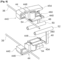
- the contact face of the rear part (448) is, as seen in particular on the figure 8 , electrically connected to one of two internal conductors 46, 48 arranged within the body 40, when the movable contact 44 is in the fixing position.
- each internal conductor 46, 48 is respectively electrically connected to one of two electrical terminals 50, 52.
- Each internal conductor 46, 48 comprises for this purpose a contact part 460, 480 forming a flexible strip and configured to come into contact with the connecting conductor 426 when the corresponding movable contact 44 is in the fixing position.
- Each movable contact is movable in translation relative to the body 40, along a first axis perpendicular to the surface of the fixing rail 3 when the adapter module 40 is attached to it, between an advanced position, visible on the figures 3 And 4 , and a withdrawn position, visible on the figures 2 And 6 .
- each movable contact 44 is in the example secured to a respective plate 54 mounted in translation in the body 40 of the adapter module 4, and sliding in an internal groove 56 formed in the body 40, in the example a T-shaped groove.
- each plate 54 comprises in the lower part a tongue 540 of adapted shape, for example of complementary shape to the internal groove 56.
- Each movable contact 44 is furthermore movable in translation relative to the body 40 along a second axis perpendicular to the first axis and perpendicular to the axis of elongation of the fixing rail 30. Each movable contact 44 is thus movable between a low position, visible on the figures 2 , 5 , And 6 , and a high position, visible on the figures 3 And 4 .
- each movable contact is mounted in translation on the corresponding plate 54.
- each plate 54 comprises a barrel 542 sliding in a complementary shaped housing 452 formed in the corresponding movable contact 44.
- each plate 54 accommodates an elastic return device, such as a spring 544, urging the corresponding movable contact 44 towards its high position.
- an elastic return device such as a spring 544, urging the corresponding movable contact 44 towards its high position.
- the high and forward position of the movable contacts 44 corresponds to the engagement position, while the low and retracted position of the movable contacts 44 corresponds to the fixing position.
- the movable contacts 44 are in their engagement position, i.e. their high and advanced position. In this position, the spacing between the front parts 440 (and more precisely between the returns 444) of the two movable contacts 44 is greater than the spacing between the edges 32 of the fixing rail 3 (and more precisely between the returns 320).
- this configuration makes it possible, during a first step, to bring the adapter module 4 closer to the fixing rail 3 and to insert the tab 42 of the body 40 into the groove 30 of the fixing rail 3, so that the front parts 440 of the two movable contacts 44 are arranged on either side of the fixing rail 30, and in particular behind the edges 32 and the returns 320.
- the movable contacts 44 are moved again, so that they move from their advanced (and low) position to their retracted position, or fixing position.
- This final movement has the effect of interlocking the front part 440 of each movable contact 44 with the corresponding edge 32, thus allowing the adapter module 4 to be fixed to the rail of fixing.
- the free end 442 of the front part 440 of each movable contact 44 is in contact with the corresponding conductor 36, 38 of the fixing rail 3, which has the effect of electrically connecting each of these conductors 36, 38 to the corresponding internal conductor 446, as visible in the figure 8 .
- each movable contact 44 comprises an end portion 454 configured to be housed in a cavity 58 of complementary shape provided in the body 40 when the corresponding movable contact 44 is in its fixing position, as visible in the Figure 6
- This configuration makes it possible to ensure locking of the movable contacts 44 in the fixing position, under the antagonistic action of the spring 544 on the one hand (which forces the corresponding movable contact 44 towards its high position) and the cavity 58 and the rim 320 on the other hand.
- the steps described above will be reversed.
- the first step will consist of moving the movable contacts from their fixing position to their low and forward position ( Figure 5 ), knowing that in this position, the action of the springs 544 will have the effect of automatically moving the movable contacts to their advanced and high position, position in which the adapter module 4 can be removed from the fixing rail 3.
- the fixing system described above makes it possible to easily and simply ensure the fixing and electrical connection of an adapter module to the fixing rail.
- the electrical contacts 36, 38 of the fixing rail 3 are concealed by the edges 32, and thus arranged at the bottom of a cavity oriented towards the rear of the rail, these conductors are made difficult to access by a user.
- the cavities 322 will be configured so that their dimensions do not allow a user to insert a finger therein. The system according to the invention therefore has both great flexibility and great ease of use, while ensuring a high degree of safety for users.
Landscapes
- Engineering & Computer Science (AREA)
- Mechanical Engineering (AREA)
- Details Of Connecting Devices For Male And Female Coupling (AREA)
- Fittings On The Vehicle Exterior For Carrying Loads, And Devices For Holding Or Mounting Articles (AREA)
- Switch Cases, Indication, And Locking (AREA)
Description
- L'invention se rapporte au domaine des équipements de véhicules automobiles, et concerne plus précisément la fixation sur une planche de bord de véhicule automobile d'éléments divers devant être alimentés électriquement, tels qu'une prise électrique, un chargeur de téléphone, un porte-gobelet réfrigéré, etc.
- L'invention part de la constatation qu'il est aujourd'hui nécessaire d'offrir aux occupants d'un véhicule automobile souplesse et facilité dans l'utilisation de différents accessoires nomades ou portables dont ils disposent et qui nécessitent une alimentation électrique.
- On connait du document
DE102006045323 un système de fixation pour la fixation dans un habitacle de véhicule automobile d'un module adaptateur. - L'invention a ainsi pour but de proposer un système de fixation permettant la fixation d'accessoires et de modules devant être alimentés électriquement.
- À cet effet, l'invention concerne un système de fixation pour la fixation dans un habitacle de véhicule automobile d'un module adaptateur, le système de fixation comportant :
- un rail de fixation, de forme allongée, destiné à être fixé à un élément d'habillage d'un véhicule automobile, tel qu'une planche de bord, le rail de fixation comportant une face avant destinée à accueillir un module adaptateur, le rail de fixation comportant deux conducteurs électriques disposés respectivement le long d'une extrémité supérieure et d'une extrémité inférieure du rail de fixation, chaque conducteur étant disposé au fond d'une cavité ménagée dans un rebord correspondant du rail de fixation et ouverte vers l'arrière du rail de fixation ;
- au moins un module adaptateur, le module adaptateur étant configuré pour être fixé au rail de fixation de façon amovible, le module adaptateur comportant un corps et deux contacts mobiles, mobiles par rapport au corps entre une position d'engagement, dans laquelle ils permettent d'accoler le module adaptateur au rail de fixation, les contacts mobiles étant alors disposés de part et d'autre des rebords du rail de fixation, et une position de fixation, dans laquelle une partie avant formant un crochet de chaque contact mobile est en prise avec le rebord correspondant, une extrémité libre de la partie avant de chaque contact mobile comportant une face de contact, la face de contact étant alors reliée électriquement au conducteur correspondant, permettant ainsi de connecter électriquement le corps et le rail de fixation.
- Grâce à un rail de fixation intégrable dans un élément d'habillage d'un habitacle de véhicule automobile, le système de fixation conforme à l'invention offre aux occupants du véhicule une grande souplesse pour la fixation d'un ou plusieurs accessoires devant être à la fois fixés et connectés électriquement, tel qu'une prise électrique, un chargeur de dispositif électronique portable, etc. en prévoyant que la fixation au rail de fixation et la connexion électrique s'effectue au moyen des mêmes éléments, à savoir les contacts mobiles, l'invention permet de fixer et connecter électriquement un accessoire de manière simple et rapide. En prévoyant que les conducteurs du rail de fixation soient disposés au sein de cavités ouvertes vers l'arrière, les conducteurs sont difficilement accessibles et sont protégés. Le système conforme à l'invention présente ainsi un niveau de sécurité très élevé.
- Dans une réalisation, chaque contact mobile est mobile en translation par rapport au corps selon un premier axe et selon un deuxième axe, les premiers et deuxième axes étant sécants et de préférence perpendiculaires, de telle sorte que les contacts mobiles sont mobiles selon le premier axe entre une position avancée et une position reculée, et sont mobiles selon le deuxième axe entre une position basse et une position haute, la position haute et avancée des contacts mobiles correspondant à la position d'engagement, la position basse et reculée des contacts mobiles correspondant à la position de fixation.
- Dans une réalisation, chaque contact mobile est solidaire d'une plaquette respective, chaque plaquette coulissant dans une rainure respective ménagée dans le corps du module adaptateur.
- Dans une réalisation, chaque contact mobile est monté à translation sur la plaquette correspondante, chaque plaquette comportant un fût coulissant dans un logement de forme complémentaire ménagé dans le contact mobile correspondant.
- Dans une réalisation, le fût de chaque plaquette comporte un dispositif de rappel élastique, tel qu'un ressort, sollicitant le contact mobile vers sa position haute.
- Dans une réalisation, chaque contact mobile comporte une partie terminale, la partie terminale étant, dans la position de fixation du contact mobile, logée dans une cavité de forme complémentaire ménagée dans le corps du module adaptateur.
- Dans une réalisation, chaque contact mobile comporte un conducteur interne, relié électriquement à la face de contact de la partie avant du contact mobile d'une part, et à une face de contact d'une partie arrière du contact mobile d'autre part.
- Dans une réalisation, le conducteur interne de chaque contact mobile est relié électriquement à un conducteur interne respectif du corps lorsque le contact mobile est en position de fixation.
- Dans une réalisation, lorsque le module adaptateur forme un socle de prise électrique, chaque conducteur interne du corps est relié électriquement à une borne respective.
- Dans une réalisation, le rail de fixation comporte une rainure de positionnement du module adaptateur, le module adaptateur comportant une languette de forme complémentaire de la rainure, la languette étant insérée dans la rainure lorsque le module adaptateur est fixé au rail de fixation.
- L'invention concerne également un véhicule automobile comportant un système de fixation conforme à celui défini ci-dessus, le rail de fixation étant fixé dans un élément d'habillage d'habitacle du véhicule, tel qu'une planche de bord, un panneau de porte ou une console, les conducteurs du rail de fixation étant raccordés à un réseau électrique de bord du véhicule.
- La présente invention sera mieux comprise à la lecture de la description détaillée qui suit, faite en référence au dessins annexés, dans lesquels :
- [
Fig. 1 ] Lafigure 1 est vue partielle d'un habitacle de véhicule automobile comportant, le véhicule étant équipé d'un système de fixation conforme à l'invention. - [
Fig. 2 ] Lafigure 2 est une vue en perspective d'un module adaptateur et d'une portion de rail de fixation, le module connectable étant accouplé avec le rail. - [
Fig. 3 ] Lafigure 3 est une vue en coupe du module adaptateur de lafigure 1 avant accouplement avec le rail de fixation. - [
Fig. 4 ] Lafigure 4 est une vue en coupe du module adaptateur de lafigure 1 dans une première phase d'accouplement avec le rail de fixation. - [
Fig. 5 ] Lafigure 5 est une vue en coupe du module adaptateur de lafigure 1 dans une deuxième phase d'accouplement avec le rail de fixation. - [
Fig. 6 ] Lafigure 6 est une vue en coupe du module adaptateur de lafigure 1 après accouplement avec le rail de fixation. - [
Fig. 7 ] Lafigure 7 est une vue en perspective d'un contact mobile du module adaptateur de lafigure 1 . - [
Fig. 8 ] Lafigure 8 est une vue partielle en perspective du module adaptateur de lafigure 1 montrant l'agencement des connexions électriques au sein de ce module. - La
figure 1 représente partiellement un habitacle d'un véhicule 1 automobile. Le véhicule 1 comporte une planche de bord 10. La planche de bord 10 est équipée d'un système de fixation 2 conforme à l'invention, permettant de fixer simultanément, sur un rail de fixation 3 un ou plusieurs modules adaptateurs 4, tel qu'un module adaptateur formant une prise électrique pour l'alimentation d'un dispositif électronique portable ou nomade, tel qu'un ordinateur portable. - On décrit ci-après, en relation avec les
figures 2 à 8 , le fonctionnement du système de fixation conforme à l'invention. - La
figure 2 est une vue en perspective du module adaptateur 4 de lafigure 1 accouplé au rail de fixation 3, dont seule une section est représentée. Le module adaptateur 4 est dans cette configuration à la fois fixé et connecté électriquement au rail de fixation 3 . - Le rail de fixation 3 présente une forme allongée. Il comporte une face arrière destinée à être fixée à un élément d'habillage de véhicule automobile, tel que la planche de bord 10 de la
figure 1 , et une face avant, destinée à recevoir un ou plusieurs modules adaptateurs tel que le module adaptateur 4 des figures. - Le module adaptateur 4 comporte un corps 40. Le corps 40 comporte une première partie, ou partie de fixation 40a et une deuxième partie, ou partie fonctionnelle 40b, la partie fonctionnelle 40b formant dans l'exemple des figures un socle de prise électrique.
- La partie de fixation 40a du corps 40 comporte une languette 42, permettant d'assurer le positionnement du module adaptateur sur le rail de fixation 3, ce dernier comportant sur sa face avant une rainure de positionnement 30 configurée pour recevoir la languette 42.
- Lorsque le module adaptateur 4 est fixé au rail de fixation 3, le module adaptateur est retenu par l'intermédiaire de deux contacts mobiles 44 soit un contact mobile inférieur un contact mobile supérieur. Chacun de ces contacts mobiles 44 assure en outre la liaison électrique entre le rail de fixation 3 et le module adaptateur 4. Chaque contact mobile 44 est mobile entre une position d'engagement, permettant l'engagement et le désengagement du module adaptateur avec le rail de fixation 3, et une position de fixation, assurant la fixation du module adaptateur 4 sur le rail de fixation 3, ainsi qu'une connexion électrique entre ces deux éléments.
- Comme visible notamment sur les
figures 3 à 8 , chaque contact mobile 44 présente une partie avant 440 en forme de crochet, configurée pour être, dans la position de fixation du contact mobile 44, en prise avec un rebord 32 respectif du rail de fixation 3. Le rail de fixation 3 comporte ainsi un rebord 32 au niveau d'une extrémité supérieure 30a et un rebord 32 au niveau d'une extrémité inférieure 30b. Chaque rebord 32 comporte un retour 320, de façon à délimiter une cavité 322 ouverte vers l'arrière du rail de fixation. Chaque cavité 322 accueille un conducteur électrique 36, 38 respectif, disposé au fond de la cavité correspondante. L'extrémité libre 442 de la partie avant 440 de chaque contact mobile 44 constitue l'extrémité d'un retour 444, et comporte une face de contact (avant) reliée électriquement à un conducteur interne 446 intégré au contact mobile 44. Le conducteur interne 446 est disposé de façon à relier la partie avant 440 du contact mobile 44 correspondant à une partie arrière 448 opposée à la partie avant 440. Au niveau de l'extrémité libre 450 de la partie arrière, le conducteur 426 est relié électriquement à une face de contact (arrière). La face de contact de la partie arrière (448) est, comme visible notamment sur lafigure 8 , reliée électriquement à l'un de deux conducteurs internes 46, 48 disposés au sein du corps 40, lorsque le contact mobile 44 est dans la position de fixation. Dans l'exemple des figures, dans lesquelles le module adaptateur 4 forme un socle de prise électrique, chaque conducteur interne 46, 48 est respectivement relié électriquement à l'une de deux bornes électriques 50, 52. Chaque conducteur interne 46, 48 comporte à cet effet une partie de contact 460, 480 formant une lamelle souple et configurée pour entrer en contact avec le conducteur de liaison 426 lorsque le contact mobile 44 correspondant est dans la position de fixation. - Chaque contact mobile est mobile en translation par rapport au corps 40, selon un premier axe perpendiculaire à la surface du rail de fixation 3 lorsque le module adaptateur 40 est accolé à celui-ci, entre une position avancée, visible sur les
figures 3 et4 , et une position reculée, visible sur lesfigures 2 et6 . Pour permettre ce mouvement de translation, chaque contact mobile 44 est dans l'exemple solidaire d'une plaquette 54 respective montée à translation dans le corps 40 du module adaptateur 4, et coulissant dans une rainure interne 56 ménagée dans le corps 40, dans l'exemple une rainure en forme de T. À cet effet, chaque plaquette 54 comporte en partie inférieure une languette 540 de forme adaptée, par exemple de forme complémentaire de la rainure interne 56. - Chaque contact mobile 44 est en outre mobile en translation par rapport au corps 40 selon un deuxième axe perpendiculaire au premier axe et perpendiculaire à l'axe d'allongement du rail de fixation 30. Chaque contact mobile 44 est ainsi mobile entre une position basse, visible sur les
figures 2 ,5 , et6 , et une position haute, visible sur lesfigures 3 et4 . À cet effet, chaque contact mobile est monté à translation sur la plaquette 54 correspondante. Dans l'exemple des figures, chaque plaquette 54 comporte un fût 542 coulissant dans un logement de forme complémentaire 452 ménagé dans le contact mobile 44 correspondant. Le fût 542 de chaque plaquette 54 accueille un dispositif de rappel élastique, tel qu'un ressort 544, sollicitant le contact mobile 44 correspondant vers sa position haute. La position haute et avancée des contacts mobiles 44 correspondant à la position d'engagement, tandis que la position basse et reculée des contacts mobiles 44 correspond à la position de fixation. - On décrit ci-après, en relation avec les
figures 3 à 6 , les étapes de fixation du module adaptateur 4 sur le rail de fixation 3. - Comme visible sur la
figure 3 , il est nécessaire, pour fixer un module adaptateur 4 sur le rail de fixation 3, que les contacts mobiles 44 soient dans leur position d'engagement, soit leur position haute et avancée. Dans cette position, l'écartement entre les parties avant 440 (et plus précisément entre les retours 444) des deux contacts mobiles 44 est supérieure à l'écartement entre les rebords 32 du rail de fixation 3 (et plus précisément entre les retours 320). Comme visible sur lafigure 4 , cette configuration permet, lors d'une première étape, d'approcher le module adaptateur 4 du rail de fixation 3 et d'insérer la languette 42 du corps 40 dans la rainure 30 du rail de fixation 3, de sorte que les parties avant 440 des deux contacts mobiles 44 se trouvent disposées de part et d'autre du rail de fixation 30, et notamment en arrière des rebords 32 et des retours 320. - Lorsque le module adaptateur 4 est correctement positionné et accolé au rail de fixation 3, on vient, lors d'une deuxième étape, presser les contacts mobiles 44 afin que ceux-ci passent de leur position haute (et avancée) à leur position basse (et avancée), comme visible sur la
figure 5 . - Lors d'une troisième étape, visible sur la
figure 6 , on déplace à nouveau les contacts mobiles 44, afin que ceux-ci passent de leur position avancée (et basse) à leur position reculée, ou position de fixation. Ce mouvement final a pour effet d'imbriquer la partie avant 440 de chaque contact mobile 44 avec le rebord 32 correspondant, permettant ainsi la fixation du module adaptateur 4 sur le rail de fixation. Dans la position de fixation, l'extrémité libre 442 de la partie avant 440 de chaque contact mobile 44 est en contact avec le conducteur 36, 38 correspondant du rail de fixation 3, ce qui a pour effet de relier électriquement chacun de ces conducteurs 36, 38 au conducteur interne 446 correspondant, comme visible sur lafigure 8 . - Avantageusement, chaque contact mobile 44 comporte une partie terminale 454 configurée pour être logée dans une cavité 58 de forme complémentaire ménagée dans le corps 40 lorsque le contact mobile 44 correspondant est dans sa position de fixation, comme visible sur la
figure 6 . Cette configuration permet d'assurer un verrouillage des contacts mobiles 44 en position de fixation, sous l'action antagoniste du ressort 544 d'une part (qui sollicite le contact mobile 44 correspondant vers sa position haute) et la cavité 58 et le rebord 320 d'autre part. - Pour retirer le module adaptateur 4 du rail de fixation 3, on effectuera les étapes inverses à celles décrites ci-dessus. Ainsi, la première étape consistera à passer les contacts mobiles de leur position de fixation à leur position basse et avancée (
figure 5 ), sachant que dans cette position, l'action des ressorts 544 aura pour effet de faire passer automatiquement les contacts mobiles à leur position avancée et haute, position dans laquelle le module adaptateur 4 peut être retiré du rail de fixation 3. - Le système de fixation décrit ci-dessus permet d'assurer facilement et simplement la fixation et la connexion électrique d'un module adaptateur au rail de fixation. En prévoyant que les contacts électriques 36, 38 du rail de fixation 3 sont dissimulés par les rebords 32, et ainsi disposés au fond d'une cavité orientée vers l'arrière du rail, on rend ces conducteurs peu accessibles à un utilisateur. Avantageusement, les cavités 322 seront configurées pour que leurs dimension ne permettent pas à un utilisateur d'y insérer un doigt. Le système conforme à l'invention présente donc à la fois une grande souplesse et une grande facilité d'utilisation, tout en assurant un haut degré de sécurité pour les utilisateurs.
Claims (10)
- Système de fixation (2) pour la fixation dans un habitacle de véhicule (1) automobile d'un module adaptateur, le système de fixation (2) comportant :- un rail de fixation (3), de forme allongée, destiné à être fixé à un élément d'habillage d'un véhicule (1) automobile, tel qu'une planche de bord (10), le rail de fixation (3) comportant une face avant destinée à accueillir un module adaptateur (4), le rail de fixation (3) comportant deux conducteurs (36, 38) électriques disposés respectivement le long d'une extrémité supérieure (30a) et d'une extrémité inférieure (30b) du rail de fixation (3), chaque conducteur (36, 38) étant disposé au fond d'une cavité (322) ménagée dans un rebord (32) correspondant du rail de fixation (3) et ouverte vers l'arrière du rail de fixation (3) ;- au moins un module adaptateur (4), le module adaptateur (4) étant configuré pour être fixé au rail de fixation (3) de façon amovible, le module adaptateur (4) comportant un corps (40) et deux contacts mobiles (44), mobiles par rapport au corps (40) entre une position d'engagement, dans laquelle ils permettent d'accoler le module adaptateur (4) au rail de fixation (3), les contacts mobiles étant alors disposés de part et d'autre des rebords (32) du rail de fixation (3), et une position de fixation, dans laquelle une partie avant (440) formant un crochet de chaque contact mobile (44) est en prise avec le rebord (32) correspondant, une extrémité libre (442) de la partie avant (440) de chaque contact mobile (44) comportant une face de contact, la face de contact étant alors reliée électriquement au conducteur (36, 38) correspondant, permettant ainsi de connecter électriquement le module adaptateur (4) et le rail de fixation (3).
- Système de fixation (2) selon la revendication précédente, dans lequel chaque contact mobile (44) est mobile en translation par rapport au corps (40) selon un premier axe et selon un deuxième axe, les premiers et deuxième axes étant perpendiculaires, de telle sorte que les contacts mobiles sont mobiles selon le premier axe entre une position avancée et une position reculée, et sont mobiles selon le deuxième axe entre une position basse et une position haute, la position haute et avancée des contacts mobiles correspondant à la position d'engagement, la position basse et reculée des contacts mobiles correspondant à la position de fixation.
- Système de fixation (2) selon la revendication précédente, dans lequel chaque contact mobile est solidaire d'une plaquette (54) respective, chaque plaquette (54) coulissant dans une rainure (56) respective ménagée dans le corps (40) du module adaptateur (4).
- Système de fixation (2) selon la revendications précédente, dans lequel chaque contact mobile (44) est monté à translation sur la plaquette (54) correspondante, chaque plaquette (54) comportant un fût (542) coulissant dans un logement (452) de forme complémentaire ménagé dans le contact mobile (44) correspondant, et, de préférence, le fût (542) de chaque plaquette (54) comporte un dispositif de rappel élastique, tel qu'un ressort (544), sollicitant le contact mobile (44) vers sa position haute.
- Système de fixation (2) selon l'une des revendications précédentes, dans lequel chaque contact mobile (44) comporte une partie terminale (454), la partie terminale (454) étant, dans la position de fixation du contact mobile (44), logée dans une cavité (58) de forme complémentaire ménagée dans le corps (40) du module adaptateur (4).
- Système de fixation (2) selon l'une des revendications précédentes, dans lequel chaque contact mobile (44) comporte un conducteur interne (446), relié électriquement à la face de contact de la partie avant (440) du contact mobile (44) d'une part, et à une face de contact d'une partie arrière (450) du contact mobile (44) d'autre part.
- Système de fixation (2) selon la revendication précédente, dans lequel le conducteur interne (446) de chaque contact mobile (44) est relié électriquement à un conducteur interne (46, 48) respectif du corps (40) lorsque le contact mobile (44) correspondant est en position de fixation.
- Système de fixation (2) selon la revendication précédente, dans lequel, lorsque le module adaptateur forme un socle de prise électrique, chaque conducteur interne (46, 48) du corps (40) est relié électriquement à une borne (50, 52) respective.
- Système de fixation (2) selon l'une des revendications précédentes, dans lequel le rail de fixation (3) comporte une rainure (30) de positionnement du module adaptateur (4), le module adaptateur comportant une languette (42) de forme complémentaire de la rainure (30), la languette (42) étant insérée dans la rainure (30) lorsque le module adaptateur (4) est fixé au rail de fixation (3).
- Véhicule (1) automobile comportant un système de fixation (2) conforme à l'une des revendications précédentes, le rail de fixation (3) étant fixé dans un élément d'habillage (10) d'habitacle du véhicule (1), tel qu'une planche de bord, un panneau de porte ou une console, les conducteurs (36, 38) du rail de fixation (3) étant raccordés à un réseau électrique de bord du véhicule (1).
Applications Claiming Priority (2)
| Application Number | Priority Date | Filing Date | Title |
|---|---|---|---|
| FR2105833A FR3123608B1 (fr) | 2021-06-03 | 2021-06-03 | Système de fixation d’un dispositif alimenté électriquement dans un habitacle de véhicule automobile |
| PCT/FR2022/050795 WO2022254112A1 (fr) | 2021-06-03 | 2022-04-27 | Système de fixation d'un dispositif alimenté électriquement dans un habitacle de véhicule automobile |
Publications (2)
| Publication Number | Publication Date |
|---|---|
| EP4347315A1 EP4347315A1 (fr) | 2024-04-10 |
| EP4347315B1 true EP4347315B1 (fr) | 2025-05-28 |
Family
ID=77021503
Family Applications (1)
| Application Number | Title | Priority Date | Filing Date |
|---|---|---|---|
| EP22724470.4A Active EP4347315B1 (fr) | 2021-06-03 | 2022-04-27 | Système de fixation d'un dispositif alimenté électriquement dans un habitacle de véhicule automobile |
Country Status (4)
| Country | Link |
|---|---|
| EP (1) | EP4347315B1 (fr) |
| CN (1) | CN117480072A (fr) |
| FR (1) | FR3123608B1 (fr) |
| WO (1) | WO2022254112A1 (fr) |
Families Citing this family (1)
| Publication number | Priority date | Publication date | Assignee | Title |
|---|---|---|---|---|
| FR3165221A1 (fr) * | 2024-08-02 | 2026-02-06 | Stellantis Auto Sas | Dispositif de fixation d’un accessoire d’habitacle. |
Citations (2)
| Publication number | Priority date | Publication date | Assignee | Title |
|---|---|---|---|---|
| US5180089A (en) * | 1990-04-02 | 1993-01-19 | Prince Corporation | Universal vehicle accessory mounting system |
| CN105599692B (zh) * | 2016-02-19 | 2018-02-23 | 浙江电咖汽车科技有限公司 | 一种汽车仪表台手机夹持装置 |
Family Cites Families (6)
| Publication number | Priority date | Publication date | Assignee | Title |
|---|---|---|---|---|
| DE2038351C3 (de) | 1970-08-01 | 1974-05-02 | Licentia Patent-Verwaltungs-Gmbh, 6000 Frankfurt | Ständer eines Hysterese-Scheibenläufermotors |
| DE19521887C2 (de) * | 1995-06-16 | 1998-10-15 | Mc Micro Compact Car Ag | Cockpit für ein Kraftfahrzeug |
| DE19908087A1 (de) * | 1999-02-25 | 2000-08-31 | Volkswagen Ag | Horizontal verlaufende Bedienleiste mit Bedienelementen an einer Schalttafel eines Kraftfahrzeuges |
| JP2004123002A (ja) * | 2002-10-04 | 2004-04-22 | Matsushita Electric Ind Co Ltd | 画像表示装置 |
| AU2002953429A0 (en) * | 2002-12-18 | 2003-01-09 | Power And Communications Logistics Pty Limited | An elongate electrical conductor that is adapted for electrically connecting with an electrical contact |
| DE102006045323A1 (de) * | 2006-09-22 | 2008-04-03 | Volkswagen Ag | In einem Fahrzeug angeordnete Multifunktionsleiste |
-
2021
- 2021-06-03 FR FR2105833A patent/FR3123608B1/fr active Active
-
2022
- 2022-04-27 EP EP22724470.4A patent/EP4347315B1/fr active Active
- 2022-04-27 WO PCT/FR2022/050795 patent/WO2022254112A1/fr not_active Ceased
- 2022-04-27 CN CN202280039524.4A patent/CN117480072A/zh active Pending
Patent Citations (2)
| Publication number | Priority date | Publication date | Assignee | Title |
|---|---|---|---|---|
| US5180089A (en) * | 1990-04-02 | 1993-01-19 | Prince Corporation | Universal vehicle accessory mounting system |
| CN105599692B (zh) * | 2016-02-19 | 2018-02-23 | 浙江电咖汽车科技有限公司 | 一种汽车仪表台手机夹持装置 |
Also Published As
| Publication number | Publication date |
|---|---|
| WO2022254112A1 (fr) | 2022-12-08 |
| CN117480072A (zh) | 2024-01-30 |
| EP4347315A1 (fr) | 2024-04-10 |
| FR3123608B1 (fr) | 2023-04-21 |
| FR3123608A1 (fr) | 2022-12-09 |
Similar Documents
| Publication | Publication Date | Title |
|---|---|---|
| EP1442926B1 (fr) | Housse pour siège de véhicule comportant une installation vidéo portable. | |
| US20020003874A1 (en) | Telephone assembly with handset having a transmitting and/or receiving component | |
| CH693892A5 (fr) | Dispositif pour une utilisation à mains libres d'un téléphone cellulaire portable tout en conduisant. | |
| EP1038731A1 (fr) | Garniture de pavillon de véhicule automobile | |
| FR2947393A1 (fr) | Connecteur d'alimentation pour la recharge d'un vehicule electrique | |
| FR2817812A1 (fr) | Siege de vehicule automobile muni d'un ecran d'affichage video | |
| EP4347315B1 (fr) | Système de fixation d'un dispositif alimenté électriquement dans un habitacle de véhicule automobile | |
| FR2873238A1 (fr) | Connecteur electrique | |
| EP4347316B1 (fr) | Système de fixation d'un dispositif alimenté électriquement dans un habitacle de véhicule automobile | |
| WO2014075920A2 (fr) | Siège de véhicule automobile comportant un dispositif de support pour un connecteur électrique et véhicule automobile associé | |
| FR2859829A3 (fr) | Adaptateur pour connexion a une prise d'allume-cigare d'automobile | |
| EP1717106B1 (fr) | Agencement pour le support dans un véhicule automobile d'un boîtier électronique | |
| FR3140327A1 (fr) | Dispositif d’accueil pour appareil nomade dans un équipement pourvu d’une façade de style | |
| FR3137882A1 (fr) | Phare de vehicule amovible | |
| EP4320015A1 (fr) | Dispositif support d'objets pour planche de bord de véhicule automobile | |
| EP1334877B1 (fr) | Kit de branchement de téléphone sur un véhicule | |
| EP1215088B1 (fr) | Ensemble d'équipement de véhicule automobile comportant des moyens de fixation et de connexion électrique améliorés | |
| WO2007131938A1 (fr) | Dispositif support notamment pour appareil portable | |
| WO2014048508A1 (fr) | Boîtier de protection pour un appareil, et accessoire connectable à un tel boîtier | |
| FR3122374A1 (fr) | Système de fixation d’un dispositif électronique portable sur une planche de bord de véhicule automobile | |
| FR3115236A1 (fr) | Pare-soleil de véhicule automobile avec fonction clavier intégrée | |
| FR2754217A1 (fr) | Bras de support coude en deux parties pour pare-soleil | |
| FR2861667A1 (fr) | Tableau de bord de vehicule automobile et vehicule automobile correspondant | |
| FR3165221A1 (fr) | Dispositif de fixation d’un accessoire d’habitacle. | |
| WO2017178387A1 (fr) | Module d'antenne(s) pour véhicule automobile |
Legal Events
| Date | Code | Title | Description |
|---|---|---|---|
| STAA | Information on the status of an ep patent application or granted ep patent |
Free format text: STATUS: UNKNOWN |
|
| STAA | Information on the status of an ep patent application or granted ep patent |
Free format text: STATUS: THE INTERNATIONAL PUBLICATION HAS BEEN MADE |
|
| PUAI | Public reference made under article 153(3) epc to a published international application that has entered the european phase |
Free format text: ORIGINAL CODE: 0009012 |
|
| STAA | Information on the status of an ep patent application or granted ep patent |
Free format text: STATUS: REQUEST FOR EXAMINATION WAS MADE |
|
| 17P | Request for examination filed |
Effective date: 20231204 |
|
| AK | Designated contracting states |
Kind code of ref document: A1 Designated state(s): AL AT BE BG CH CY CZ DE DK EE ES FI FR GB GR HR HU IE IS IT LI LT LU LV MC MK MT NL NO PL PT RO RS SE SI SK SM TR |
|
| DAV | Request for validation of the european patent (deleted) | ||
| DAX | Request for extension of the european patent (deleted) | ||
| GRAP | Despatch of communication of intention to grant a patent |
Free format text: ORIGINAL CODE: EPIDOSNIGR1 |
|
| STAA | Information on the status of an ep patent application or granted ep patent |
Free format text: STATUS: GRANT OF PATENT IS INTENDED |
|
| INTG | Intention to grant announced |
Effective date: 20250122 |
|
| GRAS | Grant fee paid |
Free format text: ORIGINAL CODE: EPIDOSNIGR3 |
|
| GRAA | (expected) grant |
Free format text: ORIGINAL CODE: 0009210 |
|
| STAA | Information on the status of an ep patent application or granted ep patent |
Free format text: STATUS: THE PATENT HAS BEEN GRANTED |
|
| AK | Designated contracting states |
Kind code of ref document: B1 Designated state(s): AL AT BE BG CH CY CZ DE DK EE ES FI FR GB GR HR HU IE IS IT LI LT LU LV MC MK MT NL NO PL PT RO RS SE SI SK SM TR |
|
| REG | Reference to a national code |
Ref country code: GB Ref legal event code: FG4D Free format text: NOT ENGLISH |
|
| REG | Reference to a national code |
Ref country code: CH Ref legal event code: EP |
|
| REG | Reference to a national code |
Ref country code: IE Ref legal event code: FG4D Free format text: LANGUAGE OF EP DOCUMENT: FRENCH Ref country code: DE Ref legal event code: R096 Ref document number: 602022015223 Country of ref document: DE |
|
| REG | Reference to a national code |
Ref country code: DE Ref legal event code: R084 Ref document number: 602022015223 Country of ref document: DE |
|
| REG | Reference to a national code |
Ref country code: NL Ref legal event code: MP Effective date: 20250528 |
|
| PG25 | Lapsed in a contracting state [announced via postgrant information from national office to epo] |
Ref country code: FI Free format text: LAPSE BECAUSE OF FAILURE TO SUBMIT A TRANSLATION OF THE DESCRIPTION OR TO PAY THE FEE WITHIN THE PRESCRIBED TIME-LIMIT Effective date: 20250528 Ref country code: ES Free format text: LAPSE BECAUSE OF FAILURE TO SUBMIT A TRANSLATION OF THE DESCRIPTION OR TO PAY THE FEE WITHIN THE PRESCRIBED TIME-LIMIT Effective date: 20250528 |
|
| REG | Reference to a national code |
Ref country code: LT Ref legal event code: MG9D |
|
| PG25 | Lapsed in a contracting state [announced via postgrant information from national office to epo] |
Ref country code: GR Free format text: LAPSE BECAUSE OF FAILURE TO SUBMIT A TRANSLATION OF THE DESCRIPTION OR TO PAY THE FEE WITHIN THE PRESCRIBED TIME-LIMIT Effective date: 20250829 Ref country code: NO Free format text: LAPSE BECAUSE OF FAILURE TO SUBMIT A TRANSLATION OF THE DESCRIPTION OR TO PAY THE FEE WITHIN THE PRESCRIBED TIME-LIMIT Effective date: 20250828 |
|
| PG25 | Lapsed in a contracting state [announced via postgrant information from national office to epo] |
Ref country code: PL Free format text: LAPSE BECAUSE OF FAILURE TO SUBMIT A TRANSLATION OF THE DESCRIPTION OR TO PAY THE FEE WITHIN THE PRESCRIBED TIME-LIMIT Effective date: 20250528 Ref country code: NL Free format text: LAPSE BECAUSE OF FAILURE TO SUBMIT A TRANSLATION OF THE DESCRIPTION OR TO PAY THE FEE WITHIN THE PRESCRIBED TIME-LIMIT Effective date: 20250528 |
|
| PG25 | Lapsed in a contracting state [announced via postgrant information from national office to epo] |
Ref country code: BG Free format text: LAPSE BECAUSE OF FAILURE TO SUBMIT A TRANSLATION OF THE DESCRIPTION OR TO PAY THE FEE WITHIN THE PRESCRIBED TIME-LIMIT Effective date: 20250528 |
|
| PG25 | Lapsed in a contracting state [announced via postgrant information from national office to epo] |
Ref country code: HR Free format text: LAPSE BECAUSE OF FAILURE TO SUBMIT A TRANSLATION OF THE DESCRIPTION OR TO PAY THE FEE WITHIN THE PRESCRIBED TIME-LIMIT Effective date: 20250528 |
|
| PG25 | Lapsed in a contracting state [announced via postgrant information from national office to epo] |
Ref country code: RS Free format text: LAPSE BECAUSE OF FAILURE TO SUBMIT A TRANSLATION OF THE DESCRIPTION OR TO PAY THE FEE WITHIN THE PRESCRIBED TIME-LIMIT Effective date: 20250828 |
|
| PG25 | Lapsed in a contracting state [announced via postgrant information from national office to epo] |
Ref country code: IS Free format text: LAPSE BECAUSE OF FAILURE TO SUBMIT A TRANSLATION OF THE DESCRIPTION OR TO PAY THE FEE WITHIN THE PRESCRIBED TIME-LIMIT Effective date: 20250928 |
|
| PG25 | Lapsed in a contracting state [announced via postgrant information from national office to epo] |
Ref country code: LV Free format text: LAPSE BECAUSE OF FAILURE TO SUBMIT A TRANSLATION OF THE DESCRIPTION OR TO PAY THE FEE WITHIN THE PRESCRIBED TIME-LIMIT Effective date: 20250528 |
|
| REG | Reference to a national code |
Ref country code: AT Ref legal event code: MK05 Ref document number: 1798469 Country of ref document: AT Kind code of ref document: T Effective date: 20250528 |
|
| PG25 | Lapsed in a contracting state [announced via postgrant information from national office to epo] |
Ref country code: AT Free format text: LAPSE BECAUSE OF FAILURE TO SUBMIT A TRANSLATION OF THE DESCRIPTION OR TO PAY THE FEE WITHIN THE PRESCRIBED TIME-LIMIT Effective date: 20250528 Ref country code: DK Free format text: LAPSE BECAUSE OF FAILURE TO SUBMIT A TRANSLATION OF THE DESCRIPTION OR TO PAY THE FEE WITHIN THE PRESCRIBED TIME-LIMIT Effective date: 20250528 Ref country code: SM Free format text: LAPSE BECAUSE OF FAILURE TO SUBMIT A TRANSLATION OF THE DESCRIPTION OR TO PAY THE FEE WITHIN THE PRESCRIBED TIME-LIMIT Effective date: 20250528 |
|
| PG25 | Lapsed in a contracting state [announced via postgrant information from national office to epo] |
Ref country code: CZ Free format text: LAPSE BECAUSE OF FAILURE TO SUBMIT A TRANSLATION OF THE DESCRIPTION OR TO PAY THE FEE WITHIN THE PRESCRIBED TIME-LIMIT Effective date: 20250528 |
|
| PG25 | Lapsed in a contracting state [announced via postgrant information from national office to epo] |
Ref country code: EE Free format text: LAPSE BECAUSE OF FAILURE TO SUBMIT A TRANSLATION OF THE DESCRIPTION OR TO PAY THE FEE WITHIN THE PRESCRIBED TIME-LIMIT Effective date: 20250528 |
|
| PG25 | Lapsed in a contracting state [announced via postgrant information from national office to epo] |
Ref country code: SK Free format text: LAPSE BECAUSE OF FAILURE TO SUBMIT A TRANSLATION OF THE DESCRIPTION OR TO PAY THE FEE WITHIN THE PRESCRIBED TIME-LIMIT Effective date: 20250528 |
|
| PG25 | Lapsed in a contracting state [announced via postgrant information from national office to epo] |
Ref country code: IT Free format text: LAPSE BECAUSE OF FAILURE TO SUBMIT A TRANSLATION OF THE DESCRIPTION OR TO PAY THE FEE WITHIN THE PRESCRIBED TIME-LIMIT Effective date: 20250528 |
|
| REG | Reference to a national code |
Ref country code: DE Ref legal event code: R097 Ref document number: 602022015223 Country of ref document: DE |
|
| PLBE | No opposition filed within time limit |
Free format text: ORIGINAL CODE: 0009261 |
|
| STAA | Information on the status of an ep patent application or granted ep patent |
Free format text: STATUS: NO OPPOSITION FILED WITHIN TIME LIMIT |
|
| REG | Reference to a national code |
Ref country code: CH Ref legal event code: L10 Free format text: ST27 STATUS EVENT CODE: U-0-0-L10-L00 (AS PROVIDED BY THE NATIONAL OFFICE) Effective date: 20260409 |
|
| PGFP | Annual fee paid to national office [announced via postgrant information from national office to epo] |
Ref country code: FR Payment date: 20260319 Year of fee payment: 5 |