EP4345372A2 - Kesselsystem zur steuerung des brennstoffs zu einem ofen auf grundlage der temperatur einer struktur in einem überhitzerabschnitt - Google Patents
Kesselsystem zur steuerung des brennstoffs zu einem ofen auf grundlage der temperatur einer struktur in einem überhitzerabschnitt Download PDFInfo
- Publication number
- EP4345372A2 EP4345372A2 EP23213552.5A EP23213552A EP4345372A2 EP 4345372 A2 EP4345372 A2 EP 4345372A2 EP 23213552 A EP23213552 A EP 23213552A EP 4345372 A2 EP4345372 A2 EP 4345372A2
- Authority
- EP
- European Patent Office
- Prior art keywords
- temperature
- tube structure
- end portion
- furnace
- fuel
- Prior art date
- Legal status (The legal status is an assumption and is not a legal conclusion. Google has not performed a legal analysis and makes no representation as to the accuracy of the status listed.)
- Granted
Links
Images


Classifications
-
- F—MECHANICAL ENGINEERING; LIGHTING; HEATING; WEAPONS; BLASTING
- F22—STEAM GENERATION
- F22G—SUPERHEATING OF STEAM
- F22G5/00—Controlling superheat temperature
- F22G5/02—Applications of combustion-control devices, e.g. tangential-firing burners, tilting burners
-
- D—TEXTILES; PAPER
- D21—PAPER-MAKING; PRODUCTION OF CELLULOSE
- D21C—PRODUCTION OF CELLULOSE BY REMOVING NON-CELLULOSE SUBSTANCES FROM CELLULOSE-CONTAINING MATERIALS; REGENERATION OF PULPING LIQUORS; APPARATUS THEREFOR
- D21C11/00—Regeneration of pulp liquors or effluent waste waters
- D21C11/10—Concentrating spent liquor by evaporation
-
- D—TEXTILES; PAPER
- D21—PAPER-MAKING; PRODUCTION OF CELLULOSE
- D21C—PRODUCTION OF CELLULOSE BY REMOVING NON-CELLULOSE SUBSTANCES FROM CELLULOSE-CONTAINING MATERIALS; REGENERATION OF PULPING LIQUORS; APPARATUS THEREFOR
- D21C11/00—Regeneration of pulp liquors or effluent waste waters
- D21C11/12—Combustion of pulp liquors
-
- F—MECHANICAL ENGINEERING; LIGHTING; HEATING; WEAPONS; BLASTING
- F01—MACHINES OR ENGINES IN GENERAL; ENGINE PLANTS IN GENERAL; STEAM ENGINES
- F01K—STEAM ENGINE PLANTS; STEAM ACCUMULATORS; ENGINE PLANTS NOT OTHERWISE PROVIDED FOR; ENGINES USING SPECIAL WORKING FLUIDS OR CYCLES
- F01K23/00—Plants characterised by more than one engine delivering power external to the plant, the engines being driven by different fluids
- F01K23/02—Plants characterised by more than one engine delivering power external to the plant, the engines being driven by different fluids the engine cycles being thermally coupled
- F01K23/06—Plants characterised by more than one engine delivering power external to the plant, the engines being driven by different fluids the engine cycles being thermally coupled combustion heat from one cycle heating the fluid in another cycle
- F01K23/064—Plants characterised by more than one engine delivering power external to the plant, the engines being driven by different fluids the engine cycles being thermally coupled combustion heat from one cycle heating the fluid in another cycle in combination with an industrial process, e.g. chemical, metallurgical
-
- F—MECHANICAL ENGINEERING; LIGHTING; HEATING; WEAPONS; BLASTING
- F22—STEAM GENERATION
- F22B—METHODS OF STEAM GENERATION; STEAM BOILERS
- F22B35/00—Control systems for steam boilers
-
- F—MECHANICAL ENGINEERING; LIGHTING; HEATING; WEAPONS; BLASTING
- F22—STEAM GENERATION
- F22B—METHODS OF STEAM GENERATION; STEAM BOILERS
- F22B35/00—Control systems for steam boilers
- F22B35/18—Applications of computers to steam-boiler control
Definitions
- the present invention relates to a boiler system comprising a controller for monitoring a temperature of a structure in a superheater section and controlling fuel provided to a furnace based on the monitored temperature.
- black liquor which contains almost all of the inorganic cooking chemicals along with lignin and other organic matter separated from the wood during pulping in a digester.
- the black liquor is burned in a recovery boiler.
- the two main functions of the recovery boiler are to recover the inorganic cooking chemicals used in the pulping process and to make use of the chemical energy in the organic portion of the black liquor to generate steam for a paper mill.
- a superheater structure is placed in the furnace in order to extract heat by radiation and convection from the furnace gases. Saturated steam enters the superheater section, and superheated steam exits from the section.
- the superheater structure comprises a plurality of platens.
- a boiler system comprising: a furnace adapted to receive a fuel to be burned to generate hot working gases; a fuel supply structure associated with the furnace for supplying fuel to the furnace; a superheater section associated with the furnace and positioned to receive energy in the form of heat from the hot working gases, the superheater section comprising: at least one platen including at least one tube structure, the one tube structure having an end portion; and a temperature sensor for measuring the temperature of the tube structure end portion and generating a signal indicative of the temperature of the tube structure end portion; and a controller coupled to the temperature sensor for receiving and monitoring the signal from the sensor.
- the controller may control an amount of fuel provided by the supply structure to the furnace based on the signal.
- the controller may monitor the signal from the temperature sensor for rapid changes in temperature of the tube structure end portion.
- Rapid changes in temperature of the tube structure end portion may comprise a monotonic increase in temperature of least about 25 degrees F occurring over a time period of between about one to ten minutes and a monotonic decrease in temperature greater than zero in magnitude occurring over a time period of between about one to fifteen minutes.
- the controller may increase an amount of fuel supplied by the supply structure to the furnace after the temperature of the tube structure end portion has experienced rapid changes.
- the boiler system may further comprise a temperature measuring device for sensing the temperature of the working gases contacting the superheater section and generating a corresponding temperature signal to the controller.
- the controller may control the amount of fuel provided by the supply structure to the furnace such that the temperature of the working gases is below a threshold temperature until the temperature of the tube structure end portion has experienced rapid changes.
- the controller may increase an amount of fuel supplied by the supply structure to the furnace after the temperature of the tube structure end portion has experienced rapid changes.
- the controller may request an operator to input a tube structure clearing verification signal after the temperature of the tube structure end portion has experienced rapid changes.
- a monitoring system for a boiler system.
- the boiler system may comprise a furnace adapted to receive a fuel to be burned to generate hot working gases, a fuel supply structure associated with the furnace for supplying fuel to the furnace, and a superheater section associated with the furnace and positioned to receive energy in the form of heat from the hot working gases.
- the superheater section may comprise at least one platen including at least one tube structure.
- the one tube structure may have an end portion.
- the monitoring system may comprise: a sensor for measuring the temperature of the tube structure end portion and generating a signal indicative of the temperature of the tube structure end portion; and a controller coupled to the sensor for receiving and monitoring the signal from the sensor.
- the controller may monitor the signal from the temperature sensor for rapid changes in temperature of the tube structure end portion.
- the controller may generate a request to an operator to input a tube structure clearing verification signal after the temperature of the tube structure end portion has experienced rapid changes.
- the controller may increase an amount of fuel supplied by the supply structure to the furnace after the temperature of the tube structure end portion has experienced rapid changes and an operator has input a tube structure clearing verification signal.
- the controller may increase an amount of fuel supplied by the supply structure to the furnace after the temperature of the tube structure end portion has experienced rapid changes and without requiring that an operator input a tube structure clearing verification signal.
- a process for monitoring a boiler system comprising a furnace for burning a fuel to generate hot working gases, a fuel supply structure for supplying fuel to the furnace, a superheater section comprising at least one platen including at least one tube structure, the one tube structure having an end portion, and a sensor for measuring the temperature of the tube structure end portion and generating a signal indicative of the temperature of the tube structure end portion.
- the process may comprise: monitoring the signal from the sensor, and controlling an amount of fuel provided to the furnace based on the signal.
- Monitoring may comprise monitoring the signal from the temperature sensor for rapid changes in temperature of the tube structure end portion.
- Controlling may comprise increasing an amount of fuel supplied by the supply structure to the furnace after the temperature of the tube structure end portion has experienced rapid changes.
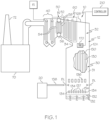
- Fig. 1 illustrates a kraft black liquor recovery boiler system 10 constructed in accordance with the present invention.
- Black liquor is a by-product of chemical pulping in a paper-making process.
- the initial concentration of "weak black liquor” is about 15%. It is concentrated to firing conditions (65% to 85% dry solids content) in an evaporator 20, and then burned in the recovery boiler system 10.
- the evaporator 20 receives the weak black liquor from washers (not shown) downstream from a cooking digester (not shown).
- the boiler system 10 comprises a recovery boiler 12 comprising a sealed housing 12A defining a furnace 30 where a fuel, e.g., black liquor, is burned to generate hot working gases, a heat transfer section 32 and a bullnose 34 in between the furnace 30 and the heat transfer section 32, see Fig. 1 .
- a fuel e.g., black liquor
- hot working gases means the gases generated when fuel is burned in the furnace.
- the boiler system 10 further comprises an economizer 40, a boiler bank 50 and a superheater section 60, all of which are located in the heat transfer section 32, see Fig. 1 .
- the hot working gases resulting from the burning of the fuel in the furnace 30 pass around the bullnose 34, travel into and through the heat transfer section 32, are then filtered through an electrostatic precipitator 70 and exit through a stack 72, see Fig. 1 .
- another fuel other than black liquor such as natural gas or fuel oil
- black liquor instead of natural gas or fuel oil may be used as the fuel in the furnace 30.
- Vertically aligned wall tubes 130 are incorporated into vertical walls 31 of the furnace 30.
- a fluid primarily water, passes through the wall tubes 130 such that energy in the form of heat from the hot working gases generated in the furnace 30 is transferred to the fluid flowing through the wall tubes 130.
- the furnace 30 has primary level air ports 132, secondary level air ports 134, and tertiary level air ports 136 for introducing air for combustion at three different height levels.
- Black liquor BL is sprayed into the furnace 30 out of spray guns 138.
- the black liquor BL is supplied to the guns 138 from the evaporator 20.
- the injectors 137 and the spray guns 138 define fuel supply structure.
- the economizer 40 receives feedwater from a supply FS.
- the feedwater may be supplied to the economizer 40 at a temperature of about 250°F.
- the economizer 40 may heat the water to a temperature of about 450°F.
- the hot working gases moving through the heat transfer section 32 supply energy in the form of heat to the economizer 40 for heating the feedwater.
- the heated water is then supplied from the economizer 40 to a top drum (steam drum) 52 of the boiler bank 50, see Fig. 1 .
- the top drum 52 functions generally as a steam-water separator.
- the water flows down a first set of tubes 54 extending from the top drum 52 to a lower drum (mud drum) 56.
- the water may be heated to a temperature of about 400-600 °F.
- a portion of the heated water flows through a second set of tubes 58 in the boiler bank 50 to the upper drum 52.
- a remaining portion of the heated water in the lower drum 56 is supplied to the wall tubes 130 in the furnace 30.
- the water flowing through the second set of tubes 58 in the boiler bank 50 and the wall tubes 130 in the furnace 30 may be heated to a saturated state. In the saturated state, the fluid is mainly a liquid, but some steam may be provided.
- the fluid in the wall tubes 130 is returned to the boiler bank 50 at the top drum 52.
- the steam is separated from the liquid in the top drum 52.
- the steam in the top drum 52 is supplied to the superheater section 60, while the water returns to the lower drum 56 via the first set of tubes 54.
- the upper and lower drums 52, 56 may be replaced by a single drum, as is known to those skilled in the art, whereby steam is supplied by the single drum to a superheater section.
- the superheater section 60 comprises first, second and third superheaters 62, 64 and 66, each of which may comprise between about 20-50 platens 62A, 64A and 66A.
- the platens 62A, 64A and 66A are suspended from the headers 62B, 64B, 66B, 62C, 64C and 66C, which are themselves suspended from overhead beams (not shown) by hanger rods 200.
- the hot working gases moving through the heat transfer section 32 supply the energy in the form of heat to the superheater section 60 for superheating the steam. It is contemplated that the superheater section 60 may comprise less than three superheaters or more than three superheaters.
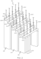
- a platen 62A from the first superheater 62 is illustrated in Fig. 3 .
- the remaining platens 62A in the first superheater 62 as well as the platens 64A and 66A in the second and third superheaters 64, 66 are constructed in generally the same manner.
- the platen 62A may comprise first, second and third separate metal tube structures 160-162, see Fig. 3 .
- the platens are schematically illustrated as rectangular structures, but are defined by tube structures.
- the tube structures 160-162 comprise inlet portions 160A-162A, which communicate with the inlet header 62B and end portions 160B-162B, which communicate with the outlet header 62C.
- the tube structure inlet portions 160A-162A and end portions 160B-162B are located above a roof 12B of the boiler housing 12A, see Figs. 1 and 3 , while intermediate portions 160C-162C of the tube structures 160-162 extend within the boiler housing 12A and are located within the heat transfer section 32.
- the tube structures 160-162 define pathways through which fluid, e.g., steam, passes from the inlet header 62B, though the tube structures 160-162 and out the outlet header 62C. It is contemplated that the platen 62A may have less than or more than three tube structures, e.g., one, two, four or five tube structures.
- the steam is heated to a superheated state in the superheater section 60.
- cooled liquid water may settle in lower bends of the tube structures 160-162 in the platens 62A, 64A and 66A.
- the liquid water prevents steam from passing through the tube structures 160-162.
- the steam moving through the tube structures 160-162 functions as a cooling fluid for the metal tube structures 160-162.
- the tube structure may become overheated, especially at an end portion 160B-162B, which may cause damage to the tube structure 160-162.
- start-up of the furnace 30 is monitored by a controller 210 to ensure that the furnace 30 is heated slowly until any liquid water in the tube structures 160-162 of the superheater section platens 62A, 64A and 66A has safely evaporated before the furnace 30 is heated to an elevated state.
- a temperature measurement device 170 which, in the illustrated embodiment, comprises an optical pyrometer, may be provided in or near the heat transfer section 32 to measure the temperature of the hot working gases in the heat transfer section 32 and entering the superheater section 60.
- the temperature measuring device 170 generates a corresponding temperature signal to the controller 210.
- the temperature sensed by the temperature measurement device 170 provides an indication of the amount of energy in the form of heat being generated by the furnace 30. Until the controller 210 has verified that liquid water in the tube structures 160-162 has been cleared, the amount of fuel provided by the injectors 137 or the spray guns 138 to the furnace 30 is controlled by the controller 210 at a low level.
- the amount of fuel provided by the injectors 137 or the spray guns 138 to the furnace 30 is controlled by the controller 210 such that the temperature of the hot working gases in the heat transfer section 32 and entering the superheater section 60, as measured by the temperature measuring device 170, is less than a predefined initial working gas threshold temperature, such as a threshold temperature falling within the range of 800-1000 degrees F, and preferably 900 degrees F. If the temperature of the hot working gases exceeds the threshold temperature, the amount of fuel provided to the furnace 30 is reduced. Once the controller 210 has verified that liquid water in the tube structures 160 has been cleared, then the controller 210 will allow the rate at which fuel is provided to the furnace 30 to increase such that the temperature of the hot working gases entering the superheater section 60 exceeds the threshold temperature.
- a predefined initial working gas threshold temperature such as a threshold temperature falling within the range of 800-1000 degrees F, and preferably 900 degrees F.
- the controller 210 comprises any device which receives input data, processes that data through computer instructions, and generates output data.
- a controller can be a hand-held device, laptop or notebook computer, desktop computer, microcomputer, digital signal processor (DSP), mainframe, server, other programmable computer devices, or any combination thereof.
- DSP digital signal processor
- the controller 210 may also be implemented using programmable logic devices such as field programmable gate arrays (FPGAs) or, alternatively, realized as application specific integrated circuits (ASICs) or similar devices.
- FPGAs field programmable gate arrays
- ASICs application specific integrated circuits
- a temperature sensor 220 such as a thermocouple in the illustrated embodiment, is provided at the end portion 160B-162B of the tube structure 160 to measure the temperature of the tube structure 160-162 at that location, see Fig. 3 .
- the temperature sensors 220 generate corresponding temperature signals to the controller 210.
- Each tube structure end portion 160B-162B is located near its corresponding outlet header. It is contemplated that a temperature sensor 220 may not be provided for all of the tube structures 160-162 in each of the platens 62A, 64A and 66A. However, it is preferred that a temperature sensor 220 is provided for at least one tube structure 160-162 in each platen 62A, 64A and 66A.
- a tube structure clearing event Liquid water evaporating in a tube structure 160-162 after furnace startup is referred to herein as a "tube structure clearing event.”
- a tube structure clearing event is characterized by rapid changes in temperature at the end portion of the tube structure.
- "rapid changes in temperature" of the end portion 160B-162B of a tube structure 160-162, as measured by a corresponding temperature sensor 220 are characterized by the temperature increasing monotonically, rapidly, e.g., over a 1-10 minute period, and significantly, e.g., by a temperature increase of at least 25 degrees F, and immediately thereafter, decreasing monotonically, rapidly, e.g., over a 1-15 minute period, by a temperature magnitude decrease equal to or less than the magnitude of the temperature increase but, in any event, the magnitude of the decrease in temperature is greater than zero.
- a plot is illustrated corresponding to a measured tube structure clearing event.
- the temperature of a tube structure end portion began to monotonically increase in temperature at about 8075 seconds from about 550 degrees F to a maximum temperature of about 700 degrees F at about 8225 seconds.
- the tube structure end portion increased in temperature by about 150 degrees F.
- the temperature of the tube structure end portion immediately began to decrease monotonically to a temperature of about 610 degrees F at about 8725 seconds.
- the tube structure end portion monotonically decreased in temperature by about 90 degrees.
- the temperature sensors 220 are monitored by the controller 210 for rapid temperature changes, i.e., a rapid increased in temperature immediately followed by a rapid decrease in temperature, indicating that fluid is moving through the entire length of their corresponding tube structures 160-162.
- the controller 210 may automatically cause (without input from an operator) the injectors 137 or spray guns 138 to increase the amount of fuel provided to the furnace 30 since the temperature of the hot working gases in the heat transfer section 32 and entering the superheater section 60 can safely exceed the predefined initial working gas threshold temperature (800-1000 degrees F in the illustrated embodiment).
- an "increase in the amount of fuel provided to the furnace” is intended to encompass increasing the rate at which fuel is input into the furnace 30 by either the injectors 137 or the spray guns 138.
- an increase in the amount of fuel provided to the furnace 30 may result when the injectors 137 increase the rate at which natural gas or fuel oil is input into the furnace 30; when the injectors 137 stop inputting natural gas or fuel oil while, at that same time, the spray guns 138 begin inputting black liquor into the furnace 30 at a rate which exceeds the rate at which natural gas or fuel oil was injected into the furnace 30; or when the spray guns 138 increase the rate at which black liquor is input into the furnace.
- the controller 210 may generate a message or otherwise indicate to an operator that a tube structure clearing event has occurred and/or request that the operator input a tube structure clearing verification signal. In an embodiment, the controller 210 will not automatically cause the injectors 137 or spray guns 138 to increase the amount of fuel provided to the furnace 30 once all of the temperature sensors 220 have provided signals to the controller 210 indicating that rapid temperature changes have occurred at their corresponding tube structure end portions, as is done by the embodiment discussed above.
- the controller 210 will wait until it receives a verification signal input from the operator, via a keypad, keyboard or other input device, indicating that the operator has verified that a tube structure clearing event has occurred. In this embodiment, only after receiving the verification signal input by the operator will the controller 210 cause the injectors 137 or spray guns 138 to increase the amount of fuel provided to the furnace 30.
- the controller 210 will automatically cause the injectors 137 or spray guns 138 to increase the amount of fuel provided to the furnace 30 once all of the temperature sensors 220 have provided signals to the controller 210 indicating that rapid temperature changes have occurred at their corresponding tube structure end portions, as is done in the embodiment discussed above.
Landscapes
- Engineering & Computer Science (AREA)
- Chemical & Material Sciences (AREA)
- Combustion & Propulsion (AREA)
- Mechanical Engineering (AREA)
- General Engineering & Computer Science (AREA)
- Physics & Mathematics (AREA)
- Thermal Sciences (AREA)
- Control Of Steam Boilers And Waste-Gas Boilers (AREA)
- Control Of Combustion (AREA)
Applications Claiming Priority (3)
| Application Number | Priority Date | Filing Date | Title |
|---|---|---|---|
| US14/202,242 US9541282B2 (en) | 2014-03-10 | 2014-03-10 | Boiler system controlling fuel to a furnace based on temperature of a structure in a superheater section |
| PCT/US2015/019445 WO2015138321A1 (en) | 2014-03-10 | 2015-03-09 | Boiler system controlling fuel to a furnace based on temperature of a structure in a superheater section |
| EP15715881.7A EP3117037B1 (de) | 2014-03-10 | 2015-03-09 | Kesselsystem zur steuerung des brennstoffs zu einem ofen auf grundlage der temperatur einer struktur in einem überhitzerabschnitt |
Related Parent Applications (2)
| Application Number | Title | Priority Date | Filing Date |
|---|---|---|---|
| EP15715881.7A Division EP3117037B1 (de) | 2014-03-10 | 2015-03-09 | Kesselsystem zur steuerung des brennstoffs zu einem ofen auf grundlage der temperatur einer struktur in einem überhitzerabschnitt |
| EP15715881.7A Division-Into EP3117037B1 (de) | 2014-03-10 | 2015-03-09 | Kesselsystem zur steuerung des brennstoffs zu einem ofen auf grundlage der temperatur einer struktur in einem überhitzerabschnitt |
Publications (4)
| Publication Number | Publication Date |
|---|---|
| EP4345372A2 true EP4345372A2 (de) | 2024-04-03 |
| EP4345372A3 EP4345372A3 (de) | 2024-05-22 |
| EP4345372C0 EP4345372C0 (de) | 2025-12-17 |
| EP4345372B1 EP4345372B1 (de) | 2025-12-17 |
Family
ID=52824543
Family Applications (2)
| Application Number | Title | Priority Date | Filing Date |
|---|---|---|---|
| EP23213552.5A Active EP4345372B1 (de) | 2014-03-10 | 2015-03-09 | Kesselsystem zur steuerung des brennstoffs zu einem ofen auf grundlage der temperatur einer struktur in einem überhitzerabschnitt |
| EP15715881.7A Active EP3117037B1 (de) | 2014-03-10 | 2015-03-09 | Kesselsystem zur steuerung des brennstoffs zu einem ofen auf grundlage der temperatur einer struktur in einem überhitzerabschnitt |
Family Applications After (1)
| Application Number | Title | Priority Date | Filing Date |
|---|---|---|---|
| EP15715881.7A Active EP3117037B1 (de) | 2014-03-10 | 2015-03-09 | Kesselsystem zur steuerung des brennstoffs zu einem ofen auf grundlage der temperatur einer struktur in einem überhitzerabschnitt |
Country Status (6)
| Country | Link |
|---|---|
| US (3) | US9541282B2 (de) |
| EP (2) | EP4345372B1 (de) |
| CA (1) | CA2941377C (de) |
| ES (2) | ES3059839T3 (de) |
| PL (2) | PL4345372T3 (de) |
| WO (1) | WO2015138321A1 (de) |
Families Citing this family (7)
| Publication number | Priority date | Publication date | Assignee | Title |
|---|---|---|---|---|
| US8381690B2 (en) | 2007-12-17 | 2013-02-26 | International Paper Company | Controlling cooling flow in a sootblower based on lance tube temperature |
| US9927231B2 (en) * | 2014-07-25 | 2018-03-27 | Integrated Test & Measurement (ITM), LLC | System and methods for detecting, monitoring, and removing deposits on boiler heat exchanger surfaces using vibrational analysis |
| US10060688B2 (en) | 2014-07-25 | 2018-08-28 | Integrated Test & Measurement (ITM) | System and methods for detecting, monitoring, and removing deposits on boiler heat exchanger surfaces using vibrational analysis |
| CA2955299C (en) | 2014-07-25 | 2017-12-12 | International Paper Company | System and method for determining a location of fouling on boiler heat transfer surface |
| CN109058971B (zh) * | 2018-05-04 | 2020-08-14 | 四川通普科技有限公司 | 一种基于NB-IoT的锅炉运行监控系统 |
| FI129238B (en) * | 2019-09-09 | 2021-10-15 | Valmet Automation Oy | A method for controlling the transition in a chemical recovery boiler and a chemical recovery boiler |
| US20210341140A1 (en) | 2020-05-01 | 2021-11-04 | International Paper Company | System and methods for controlling operation of a recovery boiler to reduce fouling |
Family Cites Families (179)
| Publication number | Priority date | Publication date | Assignee | Title |
|---|---|---|---|---|
| US2416462A (en) | 1942-11-12 | 1947-02-25 | Babcock & Wilcox Co | Method of and apparatus for recovering heat and chemicals |
| US2830440A (en) * | 1951-11-29 | 1958-04-15 | Babcock & Wilcox Co | Method of power generation with divided gas flow over a superheater and a reheater and apparatus therefor |
| US2819702A (en) * | 1951-12-29 | 1958-01-14 | Babcock & Wilcox Co | Method of and apparatus for controlling vapor temperatures |
| US3040719A (en) * | 1952-04-21 | 1962-06-26 | Bailey Meter Co | Vapor generating and superheating systems |
| US3161180A (en) * | 1952-11-26 | 1964-12-15 | Babcock & Wilcox Co | Control systems |
| US3028844A (en) * | 1952-11-26 | 1962-04-10 | Babcock & Wilcox Co | Control systems |
| US2832323A (en) | 1954-12-07 | 1958-04-29 | Riley Stoker Corp | Superheat control |
| GB802032A (en) | 1955-06-20 | 1958-09-24 | Combustion Eng | A steam generator and method of operating the same |
| CH358096A (de) * | 1958-03-12 | 1961-11-15 | Sulzer Ag | Verfahren zur Regelung der Ausgangstemperaturen an Überhitzern einer Dampferzeugeranlage und Einrichtung zur Ausübung des Verfahrens |
| US2962006A (en) * | 1958-05-19 | 1960-11-29 | Riley Stoker Corp | Steam generating unit |
| GB1022254A (en) | 1962-09-21 | 1966-03-09 | Diamond Power Speciality | Blower type cleaning for heat exchanging apparatus |
| US3274979A (en) * | 1964-09-28 | 1966-09-27 | Combustion Eng | Soot blower operation for vapor generator furnaces |
| US3207134A (en) * | 1964-10-22 | 1965-09-21 | Riley Stoker Corp | Steam generating unit |
| US3246635A (en) * | 1965-04-07 | 1966-04-19 | Combustion Eng | Vapor generator with gas recirculation |
| US3575002A (en) * | 1965-06-15 | 1971-04-13 | Combustion Eigineering Inc | Combination fossil fuel and superheated steam nuclear power plant |
| US3291106A (en) * | 1965-09-07 | 1966-12-13 | Combustion Eng | Vapor generator with gas recirculation |
| US3439376A (en) | 1965-09-09 | 1969-04-22 | Diamond Power Speciality | Long retracting soot blower |
| US3364903A (en) * | 1966-09-08 | 1968-01-23 | Combustion Eng | Steam generator with reheat temperature regulation |
| US3362384A (en) * | 1966-09-08 | 1968-01-09 | Combustion Eng | Steam generation with reheat temperature control |
| CH467973A (de) * | 1966-12-30 | 1969-01-31 | Sulzer Ag | Zwanglaufdampferzeuger |
| CA974418A (en) | 1972-02-14 | 1975-09-16 | Eugene F. Adiutori | Soot blower with gas temperature or heat flow detecting means |
| SU464031A1 (ru) | 1973-11-05 | 1975-03-15 | Предприятие П/Я Х-5263 | Рентгеновска трубка |
| US4031404A (en) * | 1974-08-08 | 1977-06-21 | Westinghouse Electric Corporation | Combined cycle electric power plant and a heat recovery steam generator having improved temperature control of the steam generated |
| US3955358A (en) * | 1974-08-08 | 1976-05-11 | Westinghouse Electric Corporation | Combined cycle electric power plant and a heat recovery steam generator with improved fluid level control therefor |
| US3965675A (en) * | 1974-08-08 | 1976-06-29 | Westinghouse Electric Corporation | Combined cycle electric power plant and a heat recovery steam generator having improved boiler feed pump flow control |
| US3974644A (en) * | 1974-08-08 | 1976-08-17 | Westinghouse Electric Corporation | Combined cycle electric power plant and heat recovery steam generator having improved multi-loop temperature control of the steam generated |
| US3972193A (en) | 1975-01-02 | 1976-08-03 | Foster Wheeler Energy Corporation | Integral separator start-up system for a vapor generator with constant pressure furnace circuitry |
| US4028884A (en) * | 1974-12-27 | 1977-06-14 | Westinghouse Electric Corporation | Control apparatus for controlling the operation of a gas turbine inlet guide vane assembly and heat recovery steam generator for a steam turbine employed in a combined cycle electric power generating plant |
| US4037469A (en) | 1975-08-11 | 1977-07-26 | Transrail Ab | Force measuring apparatus |
| US4004647A (en) | 1976-01-30 | 1977-01-25 | The Babcock & Wilcox Company | Load cell arrangement |
| US4085438A (en) | 1976-11-11 | 1978-04-18 | Copes-Vulcan Inc. | Digital sootblower control systems and methods therefor |
| US4237825A (en) * | 1978-11-06 | 1980-12-09 | Combustion Engineering, Inc. | Furnace heat absorption control |
| US4339998A (en) | 1980-04-25 | 1982-07-20 | James Finch | Fuel level indicator |
| US4380843A (en) | 1980-12-08 | 1983-04-26 | Combustion Engineering, Inc. | Droop correction structure and condensate control in sootblowers |
| US4351277A (en) | 1981-01-23 | 1982-09-28 | Tranter, Inc. | Sootblower for economizer |
| US4359800A (en) | 1981-03-05 | 1982-11-23 | The Babcock & Wilcox Company | Sootblower feed and lance tube structure with improved turbulizer system |
| US4377134A (en) * | 1981-08-03 | 1983-03-22 | Combustion Engineering, Inc. | Steam temperature control with overfire air firing |
| US4375710A (en) | 1981-09-10 | 1983-03-08 | The Babcock & Wilcox Company | Roller supporting means for long retracting sootblowers |
| US4421067A (en) | 1982-09-07 | 1983-12-20 | Deltak Corporation | Apparatus and method for soot cleaning in high-pressure heat exchangers |
| US4411204A (en) * | 1981-12-07 | 1983-10-25 | Combustion Engineering, Inc. | Method of firing a pulverized fuel-fired steam generator |
| US4422882A (en) | 1981-12-29 | 1983-12-27 | The Babcock & Wilcox Company | Pulsed liquid jet-type cleaning of highly heated surfaces |
| US4475482A (en) | 1982-08-06 | 1984-10-09 | The Babcock & Wilcox Company | Sootblowing optimization |
| US4430963A (en) | 1982-12-03 | 1984-02-14 | General Signal | System for generating dry coal weight signal for coal feeder and control system based thereon |
| US4565324A (en) | 1983-06-01 | 1986-01-21 | The Babcock & Wilcox Company | Nozzle structure for sootblower |
| US4454840A (en) | 1983-07-14 | 1984-06-19 | The Babcock & Wilcox Company | Enhanced sootblowing system |
| GB8323409D0 (en) | 1983-09-01 | 1983-10-05 | Ontario Ltd 471199 | Control of boiler operations |
| US4466383A (en) | 1983-10-12 | 1984-08-21 | The Babcock & Wilcox Company | Boiler cleaning optimization with fouling rate identification |
| US4539840A (en) | 1983-11-14 | 1985-09-10 | The Babcock & Wilcox Company | Sootblowing system with identification of model parameters |
| US4488516A (en) | 1983-11-18 | 1984-12-18 | Combustion Engineering, Inc. | Soot blower system |
| USRE32723E (en) | 1983-11-23 | 1988-08-02 | Neundorfer, Inc. | Apparatus for deslagging steam generator tubes |
| US4492187A (en) | 1983-12-05 | 1985-01-08 | The Babcock & Wilcox Company | Sootblower apparatus |
| US4567622A (en) | 1984-03-16 | 1986-02-04 | The Babcock & Wilcox Company | Sootblower nozzle apparatus |
| US4718363A (en) | 1985-02-28 | 1988-01-12 | Williames Hi-Tech Int'l Pty Ltd. | Multi-purpose seeding machine |
| ATE87077T1 (de) * | 1985-06-12 | 1993-04-15 | Metallgesellschaft Ag | Verbrennungsvorrichtung mit zirkulierender wirbelschicht. |
| US4621583A (en) | 1985-06-28 | 1986-11-11 | Measurex Corporation | System for controlling a bark-fired boiler |
| US4718376A (en) | 1985-11-01 | 1988-01-12 | Weyerhaeuser Company | Boiler sootblowing control system |
| JPS62278217A (ja) | 1986-05-27 | 1987-12-03 | Nippon Steel Corp | スラグレベル制御用熱伝対埋設ランス |
| US4776301A (en) * | 1987-03-12 | 1988-10-11 | The Babcock & Wilcox Company | Advanced steam temperature control |
| US4779690A (en) | 1987-09-15 | 1988-10-25 | Racal-Chubb Canada Limited | System for weighing containers |
| US4803959A (en) | 1988-03-24 | 1989-02-14 | The Babcock & Wilcox Company | Indexing sootblower |
| US4887431A (en) * | 1989-04-05 | 1989-12-19 | The Babcock & Wilcox Company | Superheater outlet steam temperature control |
| US4920994A (en) | 1989-09-12 | 1990-05-01 | The United States Of America As Represented By The United States Department Of Energy | Laser removal of sludge from steam generators |
| US4980674A (en) | 1989-11-27 | 1990-12-25 | Electric Power Research Institute, Inc. | Acoustic ash deposition monitor apparatus and method |
| US4986391A (en) | 1989-11-30 | 1991-01-22 | Otis Elevator Company | Elevator load weighing |
| US5050108A (en) * | 1989-11-30 | 1991-09-17 | Aptech Engineering, Inc. | Method for extending the useful life of boiler tubes |
| US5048636A (en) | 1990-02-07 | 1991-09-17 | Harness, Dickey & Pierce | Low noise wallbox for sootblower |
| US4996951A (en) | 1990-02-07 | 1991-03-05 | Westinghouse Electric Corp. | Method for soot blowing automation/optimization in boiler operation |
| US4957049A (en) * | 1990-02-22 | 1990-09-18 | Electrodyne Research Corp. | Organic waste fuel combustion system integrated with a gas turbine combined cycle |
| US5027751A (en) | 1990-07-02 | 1991-07-02 | Westinghouse Electric Corp. | Method and apparatus for optimized boiler operation |
| US5063632A (en) | 1990-12-04 | 1991-11-12 | The Babcock & Wilcox Company | Sootblower with condensate separator |
| US5065472A (en) | 1991-01-24 | 1991-11-19 | The Babcock & Wilcox Co. | Spring loaded brake assembly for indexing sootblower |
| US5113802A (en) | 1991-03-26 | 1992-05-19 | Union Camp Corporation | Method and apparatus for removing deposit from recovery boilers |
| US5090087A (en) | 1991-04-12 | 1992-02-25 | The Babcock & Wilcox Company | Hub assembly for sootblower |
| FI87604C (fi) | 1991-06-03 | 1993-01-25 | Safematic Oy | Foerfarande foer styrning av ett smoerjningssystem vid sotningsanordningar |
| US5230306A (en) | 1991-07-25 | 1993-07-27 | The Babcock & Wilcox Company | Ceramic sootblower element |
| GB9118540D0 (en) | 1991-08-29 | 1991-10-16 | Botham John | Load monitoring device |
| DE69228123T2 (de) | 1991-09-02 | 1999-06-10 | Nippon Furnace Kogyo K.K., Yokohama, Kanagawa | Boiler |
| US5241723A (en) | 1991-10-21 | 1993-09-07 | The Babcock & Wilcox Company | Nozzle structure with improved stream coherence |
| US5181482A (en) | 1991-12-13 | 1993-01-26 | Stone & Webster Engineering Corp. | Sootblowing advisor and automation system |
| SE469606B (sv) | 1991-12-20 | 1993-08-02 | Abb Carbon Ab | Foerfarande vid start och laaglastdrift av genomstroemningspanna och anordning foer genomfoerande av foerfarandet |
| US5416946A (en) | 1992-05-01 | 1995-05-23 | The Babcock & Wilcox Company | Sootblower having variable discharge |
| US5237718A (en) | 1992-05-01 | 1993-08-24 | The Babcock & Wilcox Company | Sootblower with lance bypass flow |
| DE4215997C2 (de) | 1992-05-13 | 1995-09-07 | Noell Abfall & Energietech | Verfahren zur Regelung der Müllmenge bzw. der Müllschicht auf Verbrennungsrosten |
| US5267533A (en) | 1992-07-20 | 1993-12-07 | The Babcock & Wilcox Company | Self-adjusting packing gland for sootblower |
| US5530987A (en) | 1992-07-24 | 1996-07-02 | The Babcock & Wilcox Company | Condensate drain controller |
| US5305713A (en) | 1992-07-29 | 1994-04-26 | Vadakin, Inc. | Angular rotation rotary cleaning device |
| US5261965A (en) | 1992-08-28 | 1993-11-16 | Texas Instruments Incorporated | Semiconductor wafer cleaning using condensed-phase processing |
| US5271356A (en) | 1992-10-01 | 1993-12-21 | The Babcock And Wilcox Company | Low profile sootblower nozzle |
| GB9220856D0 (en) | 1992-10-03 | 1992-11-18 | Boiler Management Systems Limi | Improvements in or relating to boiler wall cleaning |
| US5286063A (en) | 1993-01-08 | 1994-02-15 | The Babcock & Wilcox Company | Ball and socket floating seal assembly |
| US5320073A (en) | 1993-02-03 | 1994-06-14 | The Babcock And Wilcox Company | Method and apparatus of preheating a sootblower lance |
| US5375771A (en) | 1993-02-10 | 1994-12-27 | Jameel; Mohomed I. | Advanced sootblower nozzle design |
| US5353996A (en) | 1993-02-18 | 1994-10-11 | Boise Cascade Corporation | Sootblower frame and drive assembly |
| US5299533A (en) | 1993-03-22 | 1994-04-05 | The Babcock & Wilcox Company | Open beam sootblower |
| US5429076A (en) | 1993-03-22 | 1995-07-04 | The Babcock & Wilcox Company | Open beam sootblower |
| US5348774A (en) | 1993-08-11 | 1994-09-20 | Alliedsignal Inc. | Method of rapidly densifying a porous structure |
| US5423483A (en) | 1993-11-12 | 1995-06-13 | Schwade; Hans H. | Sootblower |
| DE4344906C2 (de) | 1993-12-29 | 1997-04-24 | Martin Umwelt & Energietech | Verfahren zum Regeln einzelner oder sämtlicher die Verbrennung auf einem Feuerungsrost beeinflussender Faktoren |
| US5505163B1 (en) | 1994-03-18 | 1999-07-06 | Bergemann Usa Inc | Sootblower nozzle |
| US5778831A (en) | 1994-03-18 | 1998-07-14 | Bergemann Usa, Inc. | Sootblower lance with expanded tip |
| US5423272A (en) * | 1994-04-11 | 1995-06-13 | Combustion Engineering, Inc. | Method for optimizing the operating efficiency of a fossil fuel-fired power generation system |
| US5509607A (en) | 1994-06-30 | 1996-04-23 | The Babcock & Wilcox Company | Convertible media sootblower lance tube |
| US5663489A (en) | 1994-11-14 | 1997-09-02 | Betzdearborn Inc. | Methods and apparatus for monitoring water process equipment |
| US5615734A (en) | 1994-11-16 | 1997-04-01 | Westinghouse Electric Corporation | Sludge lance inspection and verification system |
| US5605117A (en) | 1994-11-21 | 1997-02-25 | The Babcock & Wilcox Company | Articulating sootblower |
| DE19504308C1 (de) * | 1995-02-09 | 1996-08-08 | Siemens Ag | Verfahren und Vorrichtung zum Anfahren eines Durchlaufdampferzeugers |
| DE19528438C2 (de) | 1995-08-02 | 1998-01-22 | Siemens Ag | Verfahren und System zum Anfahren eines Durchlaufdampferzeugers |
| US5549305A (en) | 1995-04-07 | 1996-08-27 | Freund; Melvin A. | Sootblower packing gland |
| EP0828984B1 (de) | 1995-05-30 | 2002-02-27 | Clyde Bergemann GmbH | Antriebssystem für wasserlanzenbläser mit gehäuse für sperr- und spülmedium und verfahren zum betrieb |
| US5619771A (en) | 1995-08-11 | 1997-04-15 | Effox, Inc. | Oscillating and reverse cleaning sootblower |
| US5626184A (en) | 1995-08-24 | 1997-05-06 | Abb Air Preheater, Inc. | Sootblower |
| US5675863A (en) | 1995-08-28 | 1997-10-14 | Combustion Engineering, Inc. | Full coverage sootblower |
| FR2743215B1 (fr) | 1995-12-27 | 1998-02-13 | Electricite De France | Procede et dispositif de restauration de l'etancheite d'organes de raccordement tels que des boites a eau d'alternateurs a refroidissement mixte eau-hydrogene |
| US5765510A (en) | 1996-04-26 | 1998-06-16 | Dltk, Inc. | Retractable, sealed sootblower for high pressure, high temperature applications |
| US5740745A (en) | 1996-09-20 | 1998-04-21 | Nalco Fuel Tech | Process for increasing the effectiveness of slag control chemicals for black liquor recovery and other combustion units |
| US5769035A (en) | 1996-10-24 | 1998-06-23 | Mcdermott Technology, Inc. | Boiler furnace puff sootblower |
| FI970438A0 (fi) * | 1996-12-19 | 1997-02-03 | Kvaerner Pulping Oy | Foerfarande i panna, saerskilt i sodapanna |
| US5778830A (en) | 1997-01-02 | 1998-07-14 | Combustion Engineering, Inc. | Closed frame sootblower with top access |
| US5836268A (en) | 1997-01-02 | 1998-11-17 | Combustion Engineering, Inc. | Sootblower with travelling limit switch |
| US5769034A (en) | 1997-01-17 | 1998-06-23 | Zilka; Frank | Device, system and method for on-line explosive deslagging |
| US6431073B1 (en) | 1998-01-14 | 2002-08-13 | North American Industrial Services, Inc. | Device, system and method for on-line explosive deslagging |
| US6321690B1 (en) | 1997-01-17 | 2001-11-27 | North American Industrial Services, Inc. | Device, system and method for on-line explosive deslagging |
| US6755156B1 (en) | 1999-09-13 | 2004-06-29 | Northamerican Industrial Services, Inc. | Device, system and method for on-line explosive deslagging |
| JPH10274408A (ja) | 1997-01-30 | 1998-10-13 | Sumitomo Metal Ind Ltd | 廃熱回収用ボイラのスートブロワ運転方法 |
| US5756880A (en) | 1997-02-13 | 1998-05-26 | Betzdearborn Inc. | Methods and apparatus for monitoring water process equipment |
| US6244098B1 (en) | 1997-02-13 | 2001-06-12 | Betzdearborn Inc. | Methods and apparatus for monitoring water process equipment |
| US6109096A (en) | 1997-02-13 | 2000-08-29 | Betzdearborn Inc. | Methods and apparatus for monitoring water process equipment |
| US5920951A (en) | 1997-04-03 | 1999-07-13 | Diamond Power International, Inc. | Parameter sensing sootblower |
| DE19717378A1 (de) | 1997-04-24 | 1998-10-29 | Martin Umwelt & Energietech | Verfahren und Vorrichtung zum Entfernen von Ablagerungen in und an Zuführungsdüsen oder Zuführungsrohren von Feuerungsanlagen |
| US5992337A (en) * | 1997-09-26 | 1999-11-30 | Air Liquide America Corporation | Methods of improving productivity of black liquor recovery boilers |
| US6437285B1 (en) | 1998-06-02 | 2002-08-20 | General Lasertronics Corporation | Method and apparatus for treating interior cylindrical surfaces and ablating surface material thereon |
| US5943865A (en) * | 1998-12-03 | 1999-08-31 | Cohen; Mitchell B. | Reheating flue gas for selective catalytic systems |
| EP1063021A1 (de) | 1999-06-21 | 2000-12-27 | Frigomat S.p.a. | Reinigungsvorrichtung für Anlagen zur Abgabe von flüssigen oder pastösen Nahrungsmittelprodukten |
| US6065528A (en) | 1999-08-09 | 2000-05-23 | Abb Air Preheater, Inc. | Air preheater cleaner |
| US6325025B1 (en) | 1999-11-09 | 2001-12-04 | Applied Synergistics, Inc. | Sootblowing optimization system |
| US6170117B1 (en) | 1999-11-15 | 2001-01-09 | Abb Air Preheater, Inc. | Multiple rake sootblower with internal valving manifold |
| US6323442B1 (en) | 1999-12-07 | 2001-11-27 | International Paper Company | System and method for measuring weight of deposit on boiler superheaters |
| AU2001227893A1 (en) | 2000-01-12 | 2001-07-24 | Diamond Power International, Inc. | Sootblower lance tube for dual cleaning media |
| JP4702761B2 (ja) | 2000-01-14 | 2011-06-15 | バブコック日立株式会社 | 音波式スートブロアとその運用方法 |
| DE10009831A1 (de) | 2000-03-01 | 2001-09-13 | Clyde Bergemann Gmbh | Wasserlanzenbläser mit Überwachungseinrichtung für die Qualität des Wasserstrahls und Verfahren zu dessen Betrieb |
| AU2001286955A1 (en) | 2000-08-31 | 2002-03-13 | Clyde Bergemann, Inc. | Sootblower lance port with leak resistant cardon joint |
| US6772775B2 (en) | 2000-12-22 | 2004-08-10 | Diamond Power International, Inc. | Sootblower mechanism providing varying lance rotational speed |
| US7028926B2 (en) | 2001-01-12 | 2006-04-18 | Diamond Power International, Inc. | Sootblower nozzle assembly with nozzles having different geometries |
| US6764030B2 (en) | 2001-01-12 | 2004-07-20 | Diamond Power International, Inc. | Sootblower nozzle assembly with an improved downstream nozzle |
| US6575122B2 (en) | 2001-07-20 | 2003-06-10 | Diamond Power International, Inc. | Oscillating sootblower mechanism |
| US6725911B2 (en) | 2001-09-28 | 2004-04-27 | Gas Research Institute | Corrosion resistance treatment of condensing heat exchanger steel structures exposed to a combustion environment |
| JP2003156211A (ja) | 2001-11-19 | 2003-05-30 | Babcock Hitachi Kk | スートブロワ装置 |
| US6710285B2 (en) | 2002-06-01 | 2004-03-23 | First Call Explosive Solutions, Inc. | Laser system for slag removal |
| CA2488062C (en) | 2002-06-07 | 2009-08-11 | Andritz Oy | System for producing energy at a pulp mill |
| EP1535011B1 (de) | 2002-07-09 | 2017-04-19 | Clyde Bergemann, Inc. | Multimediumdrehender russbläser und automatischgesteuertes kesselreinigungssystem |
| US7055209B2 (en) | 2003-04-04 | 2006-06-06 | Jss Power Solutions, Llc | Method and apparatus for converting a sootblower from a single motor to a dual motor drive |
| US20040226758A1 (en) | 2003-05-14 | 2004-11-18 | Andrew Jones | System and method for measuring weight of deposit on boiler superheaters |
| US6736089B1 (en) | 2003-06-05 | 2004-05-18 | Neuco, Inc. | Method and system for sootblowing optimization |
| US7204208B2 (en) | 2003-06-17 | 2007-04-17 | S.A. Robotics | Method and apparatuses to remove slag |
| US7267134B2 (en) | 2004-03-15 | 2007-09-11 | United Technologies Corporation | Control of detonative cleaning apparatus |
| US7633033B2 (en) | 2004-01-09 | 2009-12-15 | General Lasertronics Corporation | Color sensing for laser decoating |
| US7017500B2 (en) | 2004-03-30 | 2006-03-28 | International Paper Company | Monitoring of fuel on a grate fired boiler |
| US7341067B2 (en) | 2004-09-27 | 2008-03-11 | International Paper Comany | Method of managing the cleaning of heat transfer elements of a boiler within a furnace |
| US7584024B2 (en) | 2005-02-08 | 2009-09-01 | Pegasus Technologies, Inc. | Method and apparatus for optimizing operation of a power generating plant using artificial intelligence techniques |
| RU2399709C2 (ru) | 2005-04-22 | 2010-09-20 | Андритц Ой | Устройство и способ выработки энергии на целлюлозном заводе |
| US7383790B2 (en) | 2005-06-06 | 2008-06-10 | Emerson Process Management Power & Water Solutions, Inc. | Method and apparatus for controlling soot blowing using statistical process control |
| DE102005035556A1 (de) | 2005-07-29 | 2007-02-01 | Clyde Bergemann Gmbh | Selektive Reinigung von Wärmeaustauscheinrichtungen im Kessel einer Verbrennungsanlage |
| US7735435B2 (en) | 2006-05-24 | 2010-06-15 | Diamond Power International, Inc. | Apparatus for cleaning a smelt spout of a combustion device |
| SE0602350L (sv) | 2006-11-06 | 2008-05-07 | Soottech Ab | En metod för ombyggnad av ett sotblåsningssystem ien återvinningspanna, en sotblåsare för en återvinningspanna och ett sotblåsningssystem inkluderande ett flertal sotblåsare |
| US8340824B2 (en) | 2007-10-05 | 2012-12-25 | Neuco, Inc. | Sootblowing optimization for improved boiler performance |
| US8381690B2 (en) | 2007-12-17 | 2013-02-26 | International Paper Company | Controlling cooling flow in a sootblower based on lance tube temperature |
| DE102008009129A1 (de) * | 2008-02-14 | 2009-08-20 | Hitachi Power Europe Gmbh | Kohlekraftwerk und Verfahren zum Betrieb des Kohlekraftwerkes |
| US8584540B2 (en) | 2008-05-13 | 2013-11-19 | Soottech Aktiebolag | Method for measuring conditions in a power boiler furnace using a sootblower |
| US8555796B2 (en) * | 2008-09-26 | 2013-10-15 | Air Products And Chemicals, Inc. | Process temperature control in oxy/fuel combustion system |
| JP5178453B2 (ja) * | 2008-10-27 | 2013-04-10 | 株式会社日立製作所 | 酸素燃焼ボイラ及び酸素燃焼ボイラの制御方法 |
| WO2010091342A2 (en) | 2009-02-06 | 2010-08-12 | Clyde Gergemann, Inc. | Sootblower having a nozzle with deep reaching jets and edge cleaning jets |
| WO2010098946A2 (en) | 2009-02-24 | 2010-09-02 | Adams Terry N | Systems and methods for controlling the operation of sootblowers |
| JP5417068B2 (ja) * | 2009-07-14 | 2014-02-12 | 株式会社日立製作所 | 酸素燃焼ボイラ及び酸素燃焼ボイラの制御方法 |
| US8714970B2 (en) * | 2009-09-21 | 2014-05-06 | Kailash & Stefan Pty Ltd | Combustion control system |
| US9091182B2 (en) * | 2010-12-20 | 2015-07-28 | Invensys Systems, Inc. | Feedwater heater control system for improved rankine cycle power plant efficiency |
| DE102011018441A1 (de) * | 2011-04-21 | 2012-10-25 | Clyde Bergemann Gmbh Maschinen- Und Apparatebau | Reinigungsgerät für eine Wärmekraftanlage, Verfahren zur Einrichtung eines Reinigungsgeräts und Verfahren zur Reinigung einer Wärmekraftanlage |
| GB201219764D0 (en) | 2012-11-02 | 2012-12-19 | Epsco Ltd | Method and apparatus for inspection of cooling towers |
| DE102013205645B3 (de) | 2013-03-28 | 2014-06-12 | Universität Stuttgart | Verfahren und Vorrichtung zur Bestimmung der Deposition in Kraftwerkskesseln und Hochtemperaturöfen |
| CA2955299C (en) | 2014-07-25 | 2017-12-12 | International Paper Company | System and method for determining a location of fouling on boiler heat transfer surface |
-
2014
- 2014-03-10 US US14/202,242 patent/US9541282B2/en active Active
-
2015
- 2015-03-09 PL PL23213552.5T patent/PL4345372T3/pl unknown
- 2015-03-09 EP EP23213552.5A patent/EP4345372B1/de active Active
- 2015-03-09 ES ES23213552T patent/ES3059839T3/es active Active
- 2015-03-09 ES ES15715881T patent/ES2985729T3/es active Active
- 2015-03-09 EP EP15715881.7A patent/EP3117037B1/de active Active
- 2015-03-09 CA CA2941377A patent/CA2941377C/en active Active
- 2015-03-09 PL PL15715881.7T patent/PL3117037T3/pl unknown
- 2015-03-09 WO PCT/US2015/019445 patent/WO2015138321A1/en not_active Ceased
-
2017
- 2017-01-09 US US15/401,852 patent/US20170114995A1/en not_active Abandoned
-
2019
- 2019-09-12 US US16/568,890 patent/US20200003410A1/en not_active Abandoned
Also Published As
| Publication number | Publication date |
|---|---|
| US20170114995A1 (en) | 2017-04-27 |
| CA2941377C (en) | 2018-06-26 |
| US20150253003A1 (en) | 2015-09-10 |
| ES3059839T3 (en) | 2026-03-24 |
| EP4345372C0 (de) | 2025-12-17 |
| ES2985729T3 (es) | 2024-11-07 |
| PL4345372T3 (pl) | 2026-04-20 |
| WO2015138321A1 (en) | 2015-09-17 |
| EP4345372A3 (de) | 2024-05-22 |
| EP4345372B1 (de) | 2025-12-17 |
| EP3117037B1 (de) | 2024-02-21 |
| PL3117037T3 (pl) | 2024-06-17 |
| US9541282B2 (en) | 2017-01-10 |
| CA2941377A1 (en) | 2015-09-17 |
| US20200003410A1 (en) | 2020-01-02 |
| EP3117037A1 (de) | 2017-01-18 |
| EP3117037C0 (de) | 2024-02-21 |
Similar Documents
| Publication | Publication Date | Title |
|---|---|---|
| CA2941377C (en) | Boiler system controlling fuel to a furnace based on temperature of a structure in a superheater section | |
| AU2015292444B2 (en) | System and method for determining a location of fouling on boiler heat transfer surface | |
| US6323442B1 (en) | System and method for measuring weight of deposit on boiler superheaters | |
| BR122019025511B1 (pt) | sistema para minimizar uma quantidade de fluxo de resfriamento e método para operar o mesmo | |
| WO2012065356A1 (zh) | 一种循环流化床锅炉各级过热器的布置结构 | |
| US20140123914A1 (en) | Once-through steam generator | |
| BR102018012545B1 (pt) | Método para controlar uma caldeira de recuperação | |
| EP3408588B1 (de) | Rückgewinnungskessel | |
| US20040226758A1 (en) | System and method for measuring weight of deposit on boiler superheaters | |
| EP1728919A1 (de) | Anordnung in einem Rückgewinnungskessel | |
| CN106369579A (zh) | 带炉水循环泵直流炉在炉水循环泵故障情况下的启动方法 | |
| US12345410B2 (en) | System and methods for controlling operation of a recovery boiler to reduce fouling | |
| US3007456A (en) | Apparatus for and method of generating and superheating steam | |
| EP3002366A1 (de) | Anordnung und verfahren in einem sodarückgewinnungskessel | |
| Taler et al. | Computer system for monitoring power boiler operation | |
| CN104913291B (zh) | 锅炉蒸汽受热面壁温的检测方法 | |
| CN112178621A (zh) | 一种蒸干后偏离热力平衡程度及蒸汽过热温度的计算方法 | |
| Zhang et al. | Effects of scaling on pressure drop and tube wall temperature of steam injection boilers reusing oil field produced water | |
| EP3339505A1 (de) | Kessel zur chemischen rückgewinnung | |
| Vasudevan | Forced-Circulation Steam Generators for SAGD Applications | |
| CN107166356A (zh) | 一种用于处理造纸废液的锅炉 |
Legal Events
| Date | Code | Title | Description |
|---|---|---|---|
| PUAI | Public reference made under article 153(3) epc to a published international application that has entered the european phase |
Free format text: ORIGINAL CODE: 0009012 |
|
| STAA | Information on the status of an ep patent application or granted ep patent |
Free format text: STATUS: REQUEST FOR EXAMINATION WAS MADE |
|
| 17P | Request for examination filed |
Effective date: 20231130 |
|
| AC | Divisional application: reference to earlier application |
Ref document number: 3117037 Country of ref document: EP Kind code of ref document: P |
|
| AK | Designated contracting states |
Kind code of ref document: A2 Designated state(s): AL AT BE BG CH CY CZ DE DK EE ES FI FR GB GR HR HU IE IS IT LI LT LU LV MC MK MT NL NO PL PT RO RS SE SI SK SM TR |
|
| REG | Reference to a national code |
Ref country code: DE Ref legal event code: R079 Free format text: PREVIOUS MAIN CLASS: F22G0005000000 Ipc: D21C0011100000 Ref country code: DE Ref legal event code: R079 Ref document number: 602015092838 Country of ref document: DE Free format text: PREVIOUS MAIN CLASS: F22G0005000000 Ipc: D21C0011100000 |
|
| PUAL | Search report despatched |
Free format text: ORIGINAL CODE: 0009013 |
|
| AK | Designated contracting states |
Kind code of ref document: A3 Designated state(s): AL AT BE BG CH CY CZ DE DK EE ES FI FR GB GR HR HU IE IS IT LI LT LU LV MC MK MT NL NO PL PT RO RS SE SI SK SM TR |
|
| RIC1 | Information provided on ipc code assigned before grant |
Ipc: F22G 5/00 20060101ALI20240415BHEP Ipc: D21C 11/12 20060101ALI20240415BHEP Ipc: D21C 11/10 20060101AFI20240415BHEP |
|
| RAP1 | Party data changed (applicant data changed or rights of an application transferred) |
Owner name: INTERNATIONAL PAPER COMPANY |
|
| GRAP | Despatch of communication of intention to grant a patent |
Free format text: ORIGINAL CODE: EPIDOSNIGR1 |
|
| STAA | Information on the status of an ep patent application or granted ep patent |
Free format text: STATUS: GRANT OF PATENT IS INTENDED |
|
| INTG | Intention to grant announced |
Effective date: 20250813 |
|
| GRAS | Grant fee paid |
Free format text: ORIGINAL CODE: EPIDOSNIGR3 |
|
| GRAA | (expected) grant |
Free format text: ORIGINAL CODE: 0009210 |
|
| STAA | Information on the status of an ep patent application or granted ep patent |
Free format text: STATUS: THE PATENT HAS BEEN GRANTED |
|
| AC | Divisional application: reference to earlier application |
Ref document number: 3117037 Country of ref document: EP Kind code of ref document: P |
|
| AK | Designated contracting states |
Kind code of ref document: B1 Designated state(s): AL AT BE BG CH CY CZ DE DK EE ES FI FR GB GR HR HU IE IS IT LI LT LU LV MC MK MT NL NO PL PT RO RS SE SI SK SM TR |
|
| REG | Reference to a national code |
Ref country code: CH Ref legal event code: F10 Free format text: ST27 STATUS EVENT CODE: U-0-0-F10-F00 (AS PROVIDED BY THE NATIONAL OFFICE) Effective date: 20251217 Ref country code: GB Ref legal event code: FG4D |
|
| REG | Reference to a national code |
Ref country code: DE Ref legal event code: R096 Ref document number: 602015092838 Country of ref document: DE |
|
| U01 | Request for unitary effect filed |
Effective date: 20260107 |
|
| U07 | Unitary effect registered |
Designated state(s): AT BE BG DE DK EE FI FR IT LT LU LV MT NL PT RO SE SI Effective date: 20260114 |
|
| U20 | Renewal fee for the european patent with unitary effect paid |
Year of fee payment: 12 Effective date: 20260122 |
|
| REG | Reference to a national code |
Ref country code: ES Ref legal event code: FG2A Ref document number: 3059839 Country of ref document: ES Kind code of ref document: T3 Effective date: 20260324 |
|
| PGFP | Annual fee paid to national office [announced via postgrant information from national office to epo] |
Ref country code: GB Payment date: 20260220 Year of fee payment: 12 |
|
| PG25 | Lapsed in a contracting state [announced via postgrant information from national office to epo] |
Ref country code: NO Free format text: LAPSE BECAUSE OF FAILURE TO SUBMIT A TRANSLATION OF THE DESCRIPTION OR TO PAY THE FEE WITHIN THE PRESCRIBED TIME-LIMIT Effective date: 20260317 |
|
| PG25 | Lapsed in a contracting state [announced via postgrant information from national office to epo] |
Ref country code: HR Free format text: LAPSE BECAUSE OF FAILURE TO SUBMIT A TRANSLATION OF THE DESCRIPTION OR TO PAY THE FEE WITHIN THE PRESCRIBED TIME-LIMIT Effective date: 20251217 |
|
| PG25 | Lapsed in a contracting state [announced via postgrant information from national office to epo] |
Ref country code: RS Free format text: LAPSE BECAUSE OF FAILURE TO SUBMIT A TRANSLATION OF THE DESCRIPTION OR TO PAY THE FEE WITHIN THE PRESCRIBED TIME-LIMIT Effective date: 20260317 |
|
| PGFP | Annual fee paid to national office [announced via postgrant information from national office to epo] |
Ref country code: PL Payment date: 20260224 Year of fee payment: 12 |