US5416946A - Sootblower having variable discharge - Google Patents
Sootblower having variable discharge Download PDFInfo
- Publication number
- US5416946A US5416946A US08/232,322 US23232294A US5416946A US 5416946 A US5416946 A US 5416946A US 23232294 A US23232294 A US 23232294A US 5416946 A US5416946 A US 5416946A
- Authority
- US
- United States
- Prior art keywords
- lance tube
- heat exchanger
- blowing medium
- rate
- sootblower
- Prior art date
- Legal status (The legal status is an assumption and is not a legal conclusion. Google has not performed a legal analysis and makes no representation as to the accuracy of the status listed.)
- Expired - Lifetime
Links
Images


Classifications
-
- F—MECHANICAL ENGINEERING; LIGHTING; HEATING; WEAPONS; BLASTING
- F28—HEAT EXCHANGE IN GENERAL
- F28G—CLEANING OF INTERNAL OR EXTERNAL SURFACES OF HEAT-EXCHANGE OR HEAT-TRANSFER CONDUITS, e.g. WATER TUBES OR BOILERS
- F28G1/00—Non-rotary, e.g. reciprocated, appliances
- F28G1/16—Non-rotary, e.g. reciprocated, appliances using jets of fluid for removing debris
- F28G1/166—Non-rotary, e.g. reciprocated, appliances using jets of fluid for removing debris from external surfaces of heat exchange conduits
-
- F—MECHANICAL ENGINEERING; LIGHTING; HEATING; WEAPONS; BLASTING
- F28—HEAT EXCHANGE IN GENERAL
- F28G—CLEANING OF INTERNAL OR EXTERNAL SURFACES OF HEAT-EXCHANGE OR HEAT-TRANSFER CONDUITS, e.g. WATER TUBES OR BOILERS
- F28G15/00—Details
- F28G15/04—Feeding and driving arrangements, e.g. power operation
Definitions
- This invention relates generally to a sootblower device for directing a fluid spray against a heat exchanger surface for cleaning the heat exchanger surface and in particular to a sootblower device having variable translational and rotational speeds along with a variable discharge of blowing medium to optimize the application of the blowing medium against the heat exchange surfaces while decreasing the time for completion of the operating cycle.
- sootblowers Cleaning highly heated surfaces, such as the surfaces of a boiler, furnace, incinerators or the like used to extract heat, has commonly been performed by devices generally known as sootblowers.
- Sootblowers typically employ water, steam, air or a combination thereof as a blowing medium which is directed through one or more nozzles against encrustations of slag, ash, scale and/or other foul materials which become deposited on the heat exchanger surfaces.
- heat exchanger is broadly used to refer to boilers, furnaces, incinerators or the like having internal surfaces in need of periodic cleaning to remove encrustations.
- sootblowers have been developed for cleaning heat exchanger surfaces.
- One type of sootblower is known as the retracting variety which employs a lance tube that is advanced into a heat exchanger through a wall port.
- the lance tube has one or more nozzles through which the cleaning or blowing medium is discharged and sprayed against the heat exchanger surfaces. After a cleaning cycle has been completed the lance tube is retracted from the heat exchanger until cleaning is again needed.
- the lance tube is often rotated so that the spray of blowing medium is directed along a spiral path against the heat exchanger surfaces.
- Retractable sootblowers are used in applications where the internal temperatures of the heat exchanger are sufficient to damage the lance tube and shorten its life if permanently installed in the heat exchanger.
- Other sootblowers employ a permanently positioned lance tubes which, during each cleaning cycle, may be rotated or rotationally oscillated back and forth to move the jet stream of the blowing medium.
- Such multiple cleanings of a surface can occur where the jet stream from two adjacent sootblowers overlap one another. As a result, during the cleaning portion of the operating cycle it is desirable to periodically terminate the flow of the blow medium from the sootblower where the jet stream will cover a previously cleaned surface.
- the jet stream will not be directed toward a heat exchanger surface in need of cleaning.
- One such situation is during the retraction stroke of the lance tube when cleaning has been performed during the insertion stroke of the lance tube (or vice versa).
- the discharging of the blowing medium is not desirable since it results in unnecessary blowing medium consumption.
- Another situation encountered is where during rotation of the sootblower lance tube, the emitted jet of blowing medium strikes surfaces to be cleaned over one or more arcs which combined are less than a full rotation of the jet. In other words, the jet is not performing a cleaning function during medium discharge over one or more portions of the rotational movement of the sootblower lance would reduce unneeded blowing medium discharge.
- controlling the speed of the lance tube (the rate at which the lance tube is inserted, retracted and rotated) both during cleaning and non-cleaning portions of the operating cycle, will optimize the time it takes to complete the operating cycle. This further limits wear on the heat exchange surfaces and the lance tube.
- Another object of this invention is to provide a sootblower in which cleaning is performed solely during either the insertion or retraction stroke of the lance tube while blowing medium discharge and lance tube speed are controlled to optimize the efficiency of the operating cycle.
- the lance tube is equipped with an inner tube extending therein creating an inner passage within the inner tube and an outer passage between the inner tube and the inner surface of the lance tube.
- the outer passage is used for supplying the blowing medium to the lance tube while the inner passage is used for return of a portion of the blowing medium for discarding externally of the heat exchanger.
- the supply of blowing medium can be reduced to a minimum value necessary for cooling and other purposes.
- the return flow path is open whereby only a portion of the blowing medium used for cooling, etc. is discharged through the nozzles and into the heat exchanger. The remainder is discharged externally of the heat exchanger.
- the speed or rate at which the lance tube is inserted, retracted and/or rotated can be varied. For example, when the nozzles and jets are directed at an already cleaned surface, the rate of rotation and/or translation can be increased to reduce the overall operating cycle time while the discharge rate of the blowing medium is decreased to reduce consumption.
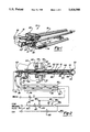
- FIG. 1 is a perspective view of a retractable sootblower including the fluid drain from the lance tube of the present invention
- FIG. 2 is a schematic diagram showing the blowing fluid supply to the lance tube and fluid drain according to the present invention.
- FIG. 3a is a translational speed versus displacement diagram generally illustrating changes in translational speed over the course of an operating cycle where cleaning is performed during insertion.
- FIG. 3b is a translational speed versus displacement diagram generally illustrating changes in translational speed over the course of an operating cycle where cleaning is performed during retraction;
- FIG. 4a is a discharge flow rate versus displacement diagram generally illustrating changes in discharge rate over the course of an operating cycle where cleaning is performed during insertion.
- FIG. 4b is a discharge flow rate versus displacement diagram generally illustrating changes in discharge rate over the course of an operating cycle where cleaning is performed during retraction.
- FIG. 5 is a front diagrammatic view illustrating operation of a sootblower in accordance with this invention.
- a sootblower of the present invention is provided to clean heat exchange surfaces during a single pass of the lance tube, either the insertion or retraction stroke.
- the sootblower is shown having a fluid bypass from the lance tube for use in regulating the flow of the blowing fluid through the lance tube nozzles.
- a sootblower of the long retracting variety incorporating the features of the present invention is shown in FIG. 1 and designated generally at 10.
- Sootblower 10 is generally of the type described in U.S. Pat. No. 3,439,376, commonly assigned to the Assignee of this invention and hereby incorporated by reference. Sootblowers of the general variety shown in FIG. 1 are well known within the art. As will become more apparent from the discussion which follows, the principals of the present invention will have applicability to sootblowers in general and are not limited to sootblowers of the retracting variety.
- a lance tube 12 is mounted to a carriage assembly 14 and is reciprocally inserted into a heat exchanger to clean surfaces by discharging the blowing medium in a jet stream against the surfaces.
- the carriage assembly is supported by a frame box 16 which is in turn mounted to a wall box (not shown) of the heat exchanger.
- the frame box 16 forms a protective housing for the sootblower 10 exteriorly of the heat exchanger.
- the carriage assembly 14 travels on rollers (not shown) along a pair of tracks 18 (only one of which is shown) which are rigidly connected to the frame box 16.
- the tracks 18 include toothed racks which are engaged by pinion gears 20 of the carriage assembly drive train to induce translation of the carriage.
- a motor 22 is mounted to the frame box and rotates a drive shaft 24 which extends the substantial length of the frame box 16 and passes through the carriage assembly 14.
- a drive train within the carriage assembly is slidably coupled to the drive shaft 24 so that the carriage assembly is capable of translational movement along the length of the drive shaft.
- the drive train rotates the pinion gears 20 causing the carriage assembly to translate along the tracks 18 and thereby advance and retract the lance 12 from the heat exchanger depending upon the direction of rotation of the drive shaft 24.
- the drive train is also operable to rotate the lance 12 about its longitudinal axis.
- a flexible supply hose 30 extends into the bottom of the carriage assembly 14 and supplies the blowing medium to the lance tube 12.
- a cable carrier 74 is preferably employed to support the length of supply hose 30 necessary to provide for travel of the carriage assembly along the length of the frame box 16.
- a flexible return hose 36 is coupled to the bottom of the carriage assembly for return of a portion of the blowing medium from the lance tube 12. Return hose 36 is likewise carried by the cable carrier 74 along with the supply hose 30.
- a programmable controller 38 which may be a common microprocessor, is coupled to position encoders which provide information to the controller regarding the translational and rotational position of the lance tube 12 and nozzles.
- the controller 38 is programmed for the specific configuration of the heat exchanger surfaces which are to be cleaned.
- the controller 38 is operable to control the rotational and translational speeds of the lance tube as well as the supply and return flow of the cleaning medium.
- the controller 38 thus regulates the amount or rate at which cleaning medium is discharged from the lance tube into the heat exchanger and the length of time it takes for the sootblower to complete an entire operating cycle.
- Lance tube 12 includes a radial flange 40 at its proximal end coupled to the flange 42 of a lance tube hub 44.
- the lance tube hub 44 extends through the wall 46 of the carriage assembly and is rotationally driven by spur gears 48 and 49 of the carriage assembly drive train.
- the lance tube includes at the distal end 50 a pair of nozzles 52 through which jet streams of the blowing medium are discharged from the lance tube 12 for impingement against the heat exchanger surfaces.
- the inlet supply hose 30 is coupled to the lance tube 12 through a rotary union 54 to supply cleaning fluid to the interior of the lance tube as shown by the arrows 56.
- An inner tube 60 extends through the lance tube and terminates near the distal end of the lance tube adjacent to the nozzles 52.
- the inner tube is supported within the lance tube by a plurality of spacers 62 which provide for fluid flow passed the spacers.
- the inner tube extends axially beyond the rotary union 54 and proximal end of the lance tube where it is coupled to the flexible return hose 36.
- the inner tube 60 thus divides the interior of the lance tube into two passages, an inner passage 64 within the inner tube and an outer passage 66 between the inner tube and the interior wall of the lance tube.
- the outer passage is used to supply the blowing medium to the nozzles at the end of the lance tube while the inner passage is used to return a portion of the cooling medium from the lance tube for subsequent discharge outside of the heat exchanger.
- the flow direction can be reversed with the fluid supply flowing through the inner passage with the return flow in the outer passage.
- the distal end of the inner tube is open so that the inner and outer passages are in communication with one another within the lance tube.
- the inner tube in the embodiment shown, where the nozzles are at the distal end of the lance tube, it is preferable for the inner tube to extend to the distal end of the lance tube whereby the inner and outer flow passages are in communication with one another adjacent to the nozzles so that the supply flow of the blowing medium extends the substantial length of the lance tube before entering the return flow passage of the inner tube 60.
- a temperature probe 68 can be placed adjacent to the nozzles in the lance tube with a temperature probe signal wire 70 extending through the inner tube to a signal processor 72.
- the supply hose 30, return hose 36 and signal wire 70 are all carried by the cable carrier 74 which carries sufficient lengths of the hoses and wire to accommodate the translation of the carriage assembly along the frame box 16.
- the supply of blowing medium to the hose 30 is controlled by a flow control system 76.
- the control system 76 receives a high pressure blowing fluid through inlet 78 which can come from any of a variety of sources including a high pressure pump, plant high pressure fluid supply etc.
- the incoming fluid is first passed through a strainer 80 to remove particulate contamination.
- a solenoid valve 82 is used to open and close the system to initiate and terminate the flow of cleaning fluid at the beginning and end of each cleaning cycle.
- a three-way solenoid valve 84 is used to switch between low and high pressure as described further below. In its unenergized state, the high pressure side is open, supplying the blowing medium which then passes pressure gauge 86 and pressure switch 88. During periods when the nozzles 52 are directed toward surfaces which need to be clean, high pressure fluid flow is needed.
- the three-way valve 84 is energized, whereby the cleaning fluid is diverted through the low pressure side of the control system which includes a reducing valve 90 and a check valve 92. This provides a lower pressure and lower flow rate of the blowing medium to the lance tube for cooling the lance tube. The lower volume flow rate of the blowing medium is sufficient for cooling of the lance tube.
- the rate of rotation and translation of the lance tube can be increased so as to decrease the overall time of the operating cycle.
- the rate of rotation and translation can then be reduced for maximum cleaning efficiency.
- the rate of translation can again be increased to its maximum rate to further decrease the overall duration of the operating cycle.
- the return hose 36 and inner tube 60 are used to drain a portion of the blowing medium from the lance tube for discharge outside of the heat exchanger.
- the drain valve 94 is opened allowing flow through the inner tube and return hose 36.
- the inner tube and return hose provide a parallel flow path for the blowing medium. The relative flow restrictions through the nozzle and the drain will determine the proportion of the blowing medium which is discharged through the nozzles and the portion which is drained from the lance tube.
- the drain has a minimum flow restriction so that a majority of the blowing medium is drained from the lance tube rather than being discharged through the nozzles 52.
- the flow bypass or drain allows a flow of the blowing medium through the lance tube for cooling or other purposes while avoiding excess discharge of blowing medium into the heat exchanger.
- An air inlet 96 is provided and coupled to the supply hose 30 for use in purging condensed blowing medium or water from the lance tube to prevent unwanted dripping of the condensed fluid from the nozzles when the sootblower is not in use. This is necessary for a retractable type sootblower in which, when not in use, the lance tube is positioned externally of the heat exchanger and cools.
- a solenoid valve 98 is provided to open and close the air inlet. As the sootblower lance tube is retracted to its nonuse position outside of the heat exchanger, the valve 98 is opened as the valve 82 is closed, introducing air into the supply hose 30 to blow the remaining cleaning fluid from the lance tube.
- the air inlet 96 can also be used to initially purge condensed blowing medium from the lance tube 12 at a low pressure to prevent the condensate from being discharged against the heat exchanger surfaces where the resulting thermal shock can cause structural damage to those surfaces.
- the lance tube 12 may be inserted a distance into the heat exchanger to preheat the lance tube and vaporize the condensate before it is purged from the lance tube. If the condensate is purged at a low enough rate or pressure, preheating may not be necessary. Cleaning can then be performed during the retraction stroke.
- air inlet 96 can provide air to the supply hose 30 at either high or low pressure to be used as the blowing medium itself, as further discussed below.
- the sootblower of the present invention thus regulates the amount of the blowing medium being discharged from the lance tube into the heat exchanger by providing a return flow path for draining a portion of the blowing medium from the lance tube.
- the relative restrictions to fluid flow through the drain and the nozzles will determine the proportion of blowing medium being drained and being discharged into the heat exchanger.
- the sootblower of the present invention enables the discharge of blowing medium into the heat exchanger to be significantly reduced during periods of a cleaning cycle in which the nozzles are not directed toward surfaces to be cleaned, while at the same time enabling a flow rate of blowing medium through the lance tube sufficient for cooling purposes yet not discharging that entire flow into the heat exchanger but rather draining a portion of that from the lance tube and heat exchanger.
- the present invention provides a sootblower which is intended to perform cleaning during a single pass of the lance tube, either on the insertion or retraction stroke.
- the translational speed is maintained at a reduced speed to optimize cleaning.
- the rate of discharge of the blowing medium is held at a high rate to also optimize cleaning.
- the translational speed and the discharge rate can be accordingly varied during the cleaning stroke so as to increase the speed of the lance tube and decrease the discharge rate of the blowing medium during any non-cleaning periods of the cleaning stroke.
- the discharge flow rate is decreased to conserve consumption of the blowing medium and the translational speed of the lance tube may be increased so as to reduce the overall time for retraction. If the blowing medium is being supplied at a rate sufficient to cool the lance tube during the non-cleaning stroke, it might prove cost efficient to hold the translational speed of the lance tube constant.
- the invention can operate where the retraction stroke of the lance tube is the cleaning stroke of the operating cycle. This is shown in FIGS. 3b and 4b.
- the translational speed is high while the discharge rate is kept low.
- the translational speed of the lance tube is reduced and the discharge rate of the blowing medium is increased. While the translational speed and discharge rate are shown as being constant in the Figures during the cleaning stroke, it is again understood that they could be varied according to the specific heat exchange surface configurations.
- the combination of single pass cleaning, varying the speed of the lance tube and varying the rate of blowing medium discharge efficiently allows the sootblower to perform all of its cleaning during a single pass or stroke of the operating cycle. If sufficient cooling is provided, the present invention can achieve single pass cleaning while maintaining the lance tube at a constant speed.
- blowing mediums and discharge rates can be utilized.
- steam can be efficiently used as the blowing medium when discharged at a high pressure rate during the cleaning stroke and discharged at a low rate or pressure during the non-cleaning stroke.
- the speed at which the lance tube moves within the heat exchange can remain constant and need not been increased.
- Another constant speed alternative uses steam, provided at an increased rate, as the blowing medium during cleaning and air through the air inlet 96, at a reduced or low pressure rate, as the blowing medium during the non-cleaning stroke of the operating cycle.
- air could be used during both the cleaning and non-cleaning portions of the operating cycle when respectively supplied at an increased and decreased rate through the air inlet 96.
- Another alternate combination uses water provided at an increased rate as the blowing medium during the cleaning stroke and air, provided at a decreased rate, as the blowing medium during the non-cleaning stroke of the operating cycle.
- the rate can be varied during a single rotation of the lance tube. This would be useful where the jet 149 emitted from nozzles 52 strikes a surface to be cleaned over less than a full rotation of the lance tube, for example where cleaning of boiler wing walls is required. Such operation is shown with reference to FIG. 5.
- Lance tube 12 is being inserted into a boiler 136 along an axis which would extend out of the plane of the drawing.
- Vertical heated surfaces often referred to as divider walls or wing walls 146 extend generally parallel to one another and to the insertion axis. As the lance tube 12 is inserted and rotated, rotation proceeds in the direction designated by arrows 148.
- sootblower 10 is operated to reduce the flow of emitted blowing medium from nozzle 52 during arcs 152 over each rotational cycle as depicted in FIG. 5.
Abstract
Description
Claims (20)
Priority Applications (1)
| Application Number | Priority Date | Filing Date | Title |
|---|---|---|---|
| US08/232,322 US5416946A (en) | 1992-05-01 | 1994-04-25 | Sootblower having variable discharge |
Applications Claiming Priority (4)
| Application Number | Priority Date | Filing Date | Title |
|---|---|---|---|
| US07/877,641 US5237718A (en) | 1992-05-01 | 1992-05-01 | Sootblower with lance bypass flow |
| US07/877,987 US5337438A (en) | 1992-05-04 | 1992-05-04 | Method and apparatus for constant progression of a cleaning jet across heated surfaces |
| US3157793A | 1993-03-15 | 1993-03-15 | |
| US08/232,322 US5416946A (en) | 1992-05-01 | 1994-04-25 | Sootblower having variable discharge |
Related Parent Applications (1)
| Application Number | Title | Priority Date | Filing Date |
|---|---|---|---|
| US3157793A Continuation | 1992-05-01 | 1993-03-15 |
Publications (1)
| Publication Number | Publication Date |
|---|---|
| US5416946A true US5416946A (en) | 1995-05-23 |
Family
ID=27363910
Family Applications (1)
| Application Number | Title | Priority Date | Filing Date |
|---|---|---|---|
| US08/232,322 Expired - Lifetime US5416946A (en) | 1992-05-01 | 1994-04-25 | Sootblower having variable discharge |
Country Status (1)
| Country | Link |
|---|---|
| US (1) | US5416946A (en) |
Cited By (23)
| Publication number | Priority date | Publication date | Assignee | Title |
|---|---|---|---|---|
| US5823209A (en) * | 1994-04-29 | 1998-10-20 | Bergemann Gmbh | Apparatus for the guiding of an elongated element |
| US20040006841A1 (en) * | 2002-07-09 | 2004-01-15 | Jameel Mohomed Ishag | Multi-media rotating sootblower and automatic industrial boiler cleaning system |
| EP1582836A1 (en) * | 2004-03-30 | 2005-10-05 | Diamond Power International Inc. | Sootblower with single traveling limit switch utilizing state logic controls |
| WO2008057039A1 (en) * | 2006-11-06 | 2008-05-15 | Soottech Aktiebolag | A method of rebuilding a sootblowing system of a recovery furnace, a sootblower for a recovery furnace, and a sootblowing system including a plurality of sootblowers |
| US20080185027A1 (en) * | 2007-02-06 | 2008-08-07 | Shamp Donald E | Glass furnace cleaning system |
| US20080216277A1 (en) * | 2007-03-08 | 2008-09-11 | Holden Industries, Llc | Varying helical sootblower |
| US7544646B2 (en) | 2004-10-06 | 2009-06-09 | Thomas Michael Band | Method for lubricating a sootblower |
| US20090151656A1 (en) * | 2007-12-17 | 2009-06-18 | Jones Andrew K | Controlling cooling flow in a sootblower based on lance tube temperature |
| WO2009139714A1 (en) * | 2008-05-13 | 2009-11-19 | Soottech Aktiebolag | A method for measuring conditions in a power boiler furnace using a sootblower |
| WO2010015479A1 (en) * | 2008-08-06 | 2010-02-11 | Bruendermann Georg | Soot blower |
| WO2010066610A1 (en) * | 2008-12-09 | 2010-06-17 | Clyde Bergemann Gmbh Maschinen- Und Apparatebau | Cleaning device for a convection section of a thermal power plant |
| US20100212608A1 (en) * | 2009-02-26 | 2010-08-26 | Brown Clinton A | Retractable articulating robotic sootblower |
| US7865996B1 (en) | 2009-12-18 | 2011-01-11 | Diamond Power International, Inc. | Sootblower with progressive cleaning arc |
| CN102012168A (en) * | 2010-11-10 | 2011-04-13 | 白银有色集团股份有限公司 | Exhaust heat boiler and method for cleaning ash of exhaust heat boiler by using steam |
| WO2011059455A1 (en) * | 2009-11-13 | 2011-05-19 | Good Earth Power Corporation | Process vessel with apertured tube |
| US20120305027A1 (en) * | 2011-06-03 | 2012-12-06 | Tandra Danny S | Intelligent sootblower |
| DE102011110926A1 (en) * | 2011-07-20 | 2013-01-24 | Clyde Bergemann Gmbh Maschinen- Und Apparatebau | Cleaning device for a convection section of a thermal power plant |
| WO2014142736A1 (en) * | 2013-03-08 | 2014-09-18 | Soottech Ab | Method and arrangement for reducing variations in soot blowing steam flow in a boiler |
| WO2016065256A3 (en) * | 2014-10-24 | 2016-07-28 | Hrst, Inc. | Tube spreading device and boiler cleaning system |
| US9541282B2 (en) | 2014-03-10 | 2017-01-10 | International Paper Company | Boiler system controlling fuel to a furnace based on temperature of a structure in a superheater section |
| US9915589B2 (en) | 2014-07-25 | 2018-03-13 | International Paper Company | System and method for determining a location of fouling on boiler heat transfer surface |
| US10018431B2 (en) | 2013-02-08 | 2018-07-10 | Diamond Power International, Llc | Condensate removal sootblower nozzle |
| US20180195860A1 (en) * | 2014-07-25 | 2018-07-12 | Integrated Test & Measurement (ITM), LLC | System and methods for detecting, monitoring, and removing deposits on boiler heat exchanger surfaces using vibrational analysis |
Citations (18)
| Publication number | Priority date | Publication date | Assignee | Title |
|---|---|---|---|---|
| US2883694A (en) * | 1955-06-13 | 1959-04-28 | Blaw Knox Co | Soot blower |
| US3230568A (en) * | 1964-04-20 | 1966-01-25 | Diamond Power Speciality | Variable speed soot blower |
| US3344459A (en) * | 1965-04-16 | 1967-10-03 | Spuhr & Co M | Soot blower for steam boilers |
| US3593691A (en) * | 1969-04-28 | 1971-07-20 | Steinmueller Gmbh L & C | Wide jet soot blower |
| US3701341A (en) * | 1971-03-18 | 1972-10-31 | Foster Wheeler Corp | Apparatus and process for slag deposit removal |
| US3782336A (en) * | 1971-10-21 | 1974-01-01 | Diamond Power Speciality | Method and apparatus for cleaning heated surfaces |
| US4380843A (en) * | 1980-12-08 | 1983-04-26 | Combustion Engineering, Inc. | Droop correction structure and condensate control in sootblowers |
| US4387481A (en) * | 1981-02-17 | 1983-06-14 | White Consolidated Industries, Inc. | Soot blower |
| US4437201A (en) * | 1981-11-13 | 1984-03-20 | White Consolidated Industries, Inc. | Soot blower |
| US4492187A (en) * | 1983-12-05 | 1985-01-08 | The Babcock & Wilcox Company | Sootblower apparatus |
| US4527515A (en) * | 1983-04-11 | 1985-07-09 | Halliburton Company | Steam generator cleaning apparatus control system |
| USRE32517E (en) * | 1971-10-21 | 1987-10-13 | The Babcock & Wilcox Co. | Method and apparatus for cleaning heated surfaces |
| US4718376A (en) * | 1985-11-01 | 1988-01-12 | Weyerhaeuser Company | Boiler sootblowing control system |
| US4803959A (en) * | 1988-03-24 | 1989-02-14 | The Babcock & Wilcox Company | Indexing sootblower |
| US4905900A (en) * | 1986-08-29 | 1990-03-06 | Anco Engineers, Inc. | Water cannon apparatus for cleaning a tube bundle heat exchanger, boiler, condenser, or the like |
| US5063632A (en) * | 1990-12-04 | 1991-11-12 | The Babcock & Wilcox Company | Sootblower with condensate separator |
| US5181482A (en) * | 1991-12-13 | 1993-01-26 | Stone & Webster Engineering Corp. | Sootblowing advisor and automation system |
| US5320073A (en) * | 1993-02-03 | 1994-06-14 | The Babcock And Wilcox Company | Method and apparatus of preheating a sootblower lance |
-
1994
- 1994-04-25 US US08/232,322 patent/US5416946A/en not_active Expired - Lifetime
Patent Citations (18)
| Publication number | Priority date | Publication date | Assignee | Title |
|---|---|---|---|---|
| US2883694A (en) * | 1955-06-13 | 1959-04-28 | Blaw Knox Co | Soot blower |
| US3230568A (en) * | 1964-04-20 | 1966-01-25 | Diamond Power Speciality | Variable speed soot blower |
| US3344459A (en) * | 1965-04-16 | 1967-10-03 | Spuhr & Co M | Soot blower for steam boilers |
| US3593691A (en) * | 1969-04-28 | 1971-07-20 | Steinmueller Gmbh L & C | Wide jet soot blower |
| US3701341A (en) * | 1971-03-18 | 1972-10-31 | Foster Wheeler Corp | Apparatus and process for slag deposit removal |
| USRE32517E (en) * | 1971-10-21 | 1987-10-13 | The Babcock & Wilcox Co. | Method and apparatus for cleaning heated surfaces |
| US3782336A (en) * | 1971-10-21 | 1974-01-01 | Diamond Power Speciality | Method and apparatus for cleaning heated surfaces |
| US4380843A (en) * | 1980-12-08 | 1983-04-26 | Combustion Engineering, Inc. | Droop correction structure and condensate control in sootblowers |
| US4387481A (en) * | 1981-02-17 | 1983-06-14 | White Consolidated Industries, Inc. | Soot blower |
| US4437201A (en) * | 1981-11-13 | 1984-03-20 | White Consolidated Industries, Inc. | Soot blower |
| US4527515A (en) * | 1983-04-11 | 1985-07-09 | Halliburton Company | Steam generator cleaning apparatus control system |
| US4492187A (en) * | 1983-12-05 | 1985-01-08 | The Babcock & Wilcox Company | Sootblower apparatus |
| US4718376A (en) * | 1985-11-01 | 1988-01-12 | Weyerhaeuser Company | Boiler sootblowing control system |
| US4905900A (en) * | 1986-08-29 | 1990-03-06 | Anco Engineers, Inc. | Water cannon apparatus for cleaning a tube bundle heat exchanger, boiler, condenser, or the like |
| US4803959A (en) * | 1988-03-24 | 1989-02-14 | The Babcock & Wilcox Company | Indexing sootblower |
| US5063632A (en) * | 1990-12-04 | 1991-11-12 | The Babcock & Wilcox Company | Sootblower with condensate separator |
| US5181482A (en) * | 1991-12-13 | 1993-01-26 | Stone & Webster Engineering Corp. | Sootblowing advisor and automation system |
| US5320073A (en) * | 1993-02-03 | 1994-06-14 | The Babcock And Wilcox Company | Method and apparatus of preheating a sootblower lance |
Cited By (55)
| Publication number | Priority date | Publication date | Assignee | Title |
|---|---|---|---|---|
| US5882430A (en) * | 1994-04-29 | 1999-03-16 | Bergemann Gmbh | Process for the guiding of an elongated element |
| US5823209A (en) * | 1994-04-29 | 1998-10-20 | Bergemann Gmbh | Apparatus for the guiding of an elongated element |
| US20040006841A1 (en) * | 2002-07-09 | 2004-01-15 | Jameel Mohomed Ishag | Multi-media rotating sootblower and automatic industrial boiler cleaning system |
| US6892679B2 (en) * | 2002-07-09 | 2005-05-17 | Clyde Bergemann, Inc. | Multi-media rotating sootblower and automatic industrial boiler cleaning system |
| EP1582836A1 (en) * | 2004-03-30 | 2005-10-05 | Diamond Power International Inc. | Sootblower with single traveling limit switch utilizing state logic controls |
| US20050217060A1 (en) * | 2004-03-30 | 2005-10-06 | Diamond Power International, Inc. | Sootblower with single traveling limit switch utilizing state logic control |
| US7544646B2 (en) | 2004-10-06 | 2009-06-09 | Thomas Michael Band | Method for lubricating a sootblower |
| JP2010509556A (en) * | 2006-11-06 | 2010-03-25 | スーテック アクティエボラグ | Method for rebuilding soot blower device of recovery furnace, soot blower for recovery furnace, and soot blower device including a plurality of soot blowers |
| US20100064470A1 (en) * | 2006-11-06 | 2010-03-18 | Soottech Aktiebolag | Method of rebuilding a sootblowing system of a recovery furnace, a sootblower for a recovery furnace, and a sootblowing system including a plurality of sootblowers |
| CN101535759B (en) * | 2006-11-06 | 2013-04-24 | 煤烟技术股份公司 | A method of rebuilding a sootblowing system of a recovery furnace, a sootblower for a recovery furnace, and a sootblowing system including a plurality of sootblowers |
| US8578551B2 (en) * | 2006-11-06 | 2013-11-12 | Soottech Aktiebolag | Method of rebuilding a sootblowing system of a recovery furnace, a sootblower for a recovery furnace, and a sootblowing system including a plurality of sootblowers |
| EP2079975A1 (en) * | 2006-11-06 | 2009-07-22 | Soottech Aktiebolag | A method of rebuilding a sootblowing system of a recovery furnace, a sootblower for a recovery furnace, and a sootblowing system including a plurality of sootblowers |
| WO2008057039A1 (en) * | 2006-11-06 | 2008-05-15 | Soottech Aktiebolag | A method of rebuilding a sootblowing system of a recovery furnace, a sootblower for a recovery furnace, and a sootblowing system including a plurality of sootblowers |
| EP2079975A4 (en) * | 2006-11-06 | 2014-06-25 | Soottech Aktiebolag | A method of rebuilding a sootblowing system of a recovery furnace, a sootblower for a recovery furnace, and a sootblowing system including a plurality of sootblowers |
| RU2450232C2 (en) * | 2006-11-06 | 2012-05-10 | СутТек Актиеболаг | Method of upgrading blower system of regenerator, soot blower of regenerator and blower system comprising soot blowers |
| US20080185027A1 (en) * | 2007-02-06 | 2008-08-07 | Shamp Donald E | Glass furnace cleaning system |
| US20080216277A1 (en) * | 2007-03-08 | 2008-09-11 | Holden Industries, Llc | Varying helical sootblower |
| CN102865570B (en) * | 2007-12-17 | 2015-04-08 | 国际纸业公司 | Controlling cooling flow in a sootblower based on lance tube temperature |
| US9671183B2 (en) * | 2007-12-17 | 2017-06-06 | International Paper Company | Controlling cooling flow in a sootblower based on lance tube temperature |
| US20090151656A1 (en) * | 2007-12-17 | 2009-06-18 | Jones Andrew K | Controlling cooling flow in a sootblower based on lance tube temperature |
| US20130152973A1 (en) * | 2007-12-17 | 2013-06-20 | International Paper Company | Controlling cooling flow in a sootblower based on lance tube temperature |
| US8381690B2 (en) | 2007-12-17 | 2013-02-26 | International Paper Company | Controlling cooling flow in a sootblower based on lance tube temperature |
| CN102865570A (en) * | 2007-12-17 | 2013-01-09 | 国际纸业公司 | Controlling cooling flow in a sootblower based on lance tube temperature |
| US8584540B2 (en) | 2008-05-13 | 2013-11-19 | Soottech Aktiebolag | Method for measuring conditions in a power boiler furnace using a sootblower |
| WO2009139714A1 (en) * | 2008-05-13 | 2009-11-19 | Soottech Aktiebolag | A method for measuring conditions in a power boiler furnace using a sootblower |
| US20110056313A1 (en) * | 2008-05-13 | 2011-03-10 | Soot-Tech Aktiebolag | method for measuring conditions in a power boiler furnace using a sootblower |
| CN102016476B (en) * | 2008-05-13 | 2016-12-07 | 煤烟技术股份公司 | Utilize the method that the condition in power boiler burner hearth measured by soot blower |
| WO2010015479A1 (en) * | 2008-08-06 | 2010-02-11 | Bruendermann Georg | Soot blower |
| US20110132414A1 (en) * | 2008-08-06 | 2011-06-09 | Georg Bruendermann | Soot blower |
| CN102245971A (en) * | 2008-12-09 | 2011-11-16 | 克莱德贝格曼机器设备制造有限公司 | Cleaning device for a convection section of a thermal power plant |
| WO2010066610A1 (en) * | 2008-12-09 | 2010-06-17 | Clyde Bergemann Gmbh Maschinen- Und Apparatebau | Cleaning device for a convection section of a thermal power plant |
| US20110296837A1 (en) * | 2008-12-09 | 2011-12-08 | Clyde Bergemann DRYCON GmbH Maschinen-Und Apparatebau | Cleaning device for a convection section of a thermal power plant |
| US9021653B2 (en) * | 2008-12-09 | 2015-05-05 | Clyde Bergemann GmbH Maschinem-Und Apparatebau | Cleaning device for a convection section of a thermal power plant |
| CN102245971B (en) * | 2008-12-09 | 2013-12-04 | 克莱德贝格曼机器设备制造有限公司 | Cleaning device for a convection section of a thermal power plant |
| US8176883B2 (en) | 2009-02-26 | 2012-05-15 | Diamond Power International, Inc. | Retractable articulating robotic sootblower |
| AU2010218266B2 (en) * | 2009-02-26 | 2013-07-25 | Diamond Power International, Inc. | Retractable articulating robotic sootblower |
| WO2010099008A1 (en) * | 2009-02-26 | 2010-09-02 | Diamond Power International, Inc. | Retractable articulating robotic sootblower |
| US20100212608A1 (en) * | 2009-02-26 | 2010-08-26 | Brown Clinton A | Retractable articulating robotic sootblower |
| WO2011059455A1 (en) * | 2009-11-13 | 2011-05-19 | Good Earth Power Corporation | Process vessel with apertured tube |
| US7865996B1 (en) | 2009-12-18 | 2011-01-11 | Diamond Power International, Inc. | Sootblower with progressive cleaning arc |
| CN102012168A (en) * | 2010-11-10 | 2011-04-13 | 白银有色集团股份有限公司 | Exhaust heat boiler and method for cleaning ash of exhaust heat boiler by using steam |
| CN102012168B (en) * | 2010-11-10 | 2013-07-31 | 白银有色集团股份有限公司 | Method for cleaning ash of exhaust heat boiler by using steam |
| US8381604B2 (en) * | 2011-06-03 | 2013-02-26 | Clyde Beri Emann, Inc. | Intelligent sootblower |
| US20120305027A1 (en) * | 2011-06-03 | 2012-12-06 | Tandra Danny S | Intelligent sootblower |
| US9279585B2 (en) | 2011-07-20 | 2016-03-08 | Clyde Bergemann Gmbh Maschinen-Und Apparatebau | Cleaning apparatus for a convective section of a thermal power plant |
| DE102011110926A1 (en) * | 2011-07-20 | 2013-01-24 | Clyde Bergemann Gmbh Maschinen- Und Apparatebau | Cleaning device for a convection section of a thermal power plant |
| US10018431B2 (en) | 2013-02-08 | 2018-07-10 | Diamond Power International, Llc | Condensate removal sootblower nozzle |
| WO2014142736A1 (en) * | 2013-03-08 | 2014-09-18 | Soottech Ab | Method and arrangement for reducing variations in soot blowing steam flow in a boiler |
| US9541282B2 (en) | 2014-03-10 | 2017-01-10 | International Paper Company | Boiler system controlling fuel to a furnace based on temperature of a structure in a superheater section |
| US9915589B2 (en) | 2014-07-25 | 2018-03-13 | International Paper Company | System and method for determining a location of fouling on boiler heat transfer surface |
| US20180195860A1 (en) * | 2014-07-25 | 2018-07-12 | Integrated Test & Measurement (ITM), LLC | System and methods for detecting, monitoring, and removing deposits on boiler heat exchanger surfaces using vibrational analysis |
| US10094660B2 (en) * | 2014-07-25 | 2018-10-09 | Integrated Test & Measurement (ITM), LLC | System and methods for detecting, monitoring, and removing deposits on boiler heat exchanger surfaces using vibrational analysis |
| US10724858B2 (en) * | 2014-07-25 | 2020-07-28 | Integrated Test & Measurement (ITM), LLC | System and methods for detecting, monitoring, and removing deposits on boiler heat exchanger surfaces using vibrational analysis |
| WO2016065256A3 (en) * | 2014-10-24 | 2016-07-28 | Hrst, Inc. | Tube spreading device and boiler cleaning system |
| US10605450B2 (en) | 2014-10-24 | 2020-03-31 | Hrst, Inc. | Tube spreading device and boiler cleaning system |
Similar Documents
| Publication | Publication Date | Title |
|---|---|---|
| US5416946A (en) | Sootblower having variable discharge | |
| US5237718A (en) | Sootblower with lance bypass flow | |
| JP2647331B2 (en) | Equipment to clean the boiler heating surface | |
| US6892679B2 (en) | Multi-media rotating sootblower and automatic industrial boiler cleaning system | |
| US4422882A (en) | Pulsed liquid jet-type cleaning of highly heated surfaces | |
| KR101379609B1 (en) | Retractable articulating robotic sootblower | |
| EP0144131B1 (en) | An improved sootblower apparatus for use in a boiler and method of operating the same | |
| US5320073A (en) | Method and apparatus of preheating a sootblower lance | |
| US6575122B2 (en) | Oscillating sootblower mechanism | |
| US4359800A (en) | Sootblower feed and lance tube structure with improved turbulizer system | |
| US5241723A (en) | Nozzle structure with improved stream coherence | |
| SU1429947A3 (en) | Method and apparatus for removing stuck deposits from heating surface of heat exchanger | |
| US20020078982A1 (en) | Sootblower mechanism providing varying lance rotational speed | |
| US7055209B2 (en) | Method and apparatus for converting a sootblower from a single motor to a dual motor drive | |
| EP2336704B1 (en) | Sootblower with progressive cleaning arc | |
| EP1291598B1 (en) | Apparatus for cleaning the open draft boiler surfaces in a combustion or incineration plant | |
| JPH0729387Y2 (en) | Soot blower | |
| JP2713653B2 (en) | Control method of soot blowing device | |
| JPH06281127A (en) | Soot blower for heat-exchanger using gas outside of pipe | |
| JPH08189630A (en) | Soot blower | |
| CN116989348A (en) | Hot secondary air channel communication device |
Legal Events
| Date | Code | Title | Description |
|---|---|---|---|
| FEPP | Fee payment procedure |
Free format text: PAYOR NUMBER ASSIGNED (ORIGINAL EVENT CODE: ASPN); ENTITY STATUS OF PATENT OWNER: LARGE ENTITY |
|
| STCF | Information on status: patent grant |
Free format text: PATENTED CASE |
|
| AS | Assignment |
Owner name: DIAMOND POWER INTERNATIONAL, INC., LOUISIANA Free format text: ASSIGNMENT OF ASSIGNORS INTEREST;ASSIGNOR:BABCOCK & WILCOX COMPANY, THE;REEL/FRAME:008820/0048 Effective date: 19970630 |
|
| FPAY | Fee payment |
Year of fee payment: 4 |
|
| FPAY | Fee payment |
Year of fee payment: 8 |
|
| AS | Assignment |
Owner name: CREDIT SUISSE, CAYMAN ISLANDS BRANCH, AS COLLATERA Free format text: SECURITY AGREEMENT;ASSIGNOR:DIAMOND POWER INTERNATIONAL, INC.;REEL/FRAME:017344/0605 Effective date: 20060222 |
|
| FPAY | Fee payment |
Year of fee payment: 12 |
|
| AS | Assignment |
Owner name: POWER SYSTEMS OPERATIONS, INC., OHIO Free format text: RELEASE BY SECURED PARTY;ASSIGNOR:CREDIT SUISSE AG, CAYMAN ISLANDS BRANCH;REEL/FRAME:024776/0693 Effective date: 20100503 Owner name: BABCOCK & WILCOX EBENSBURG POWER, INC., OHIO Free format text: RELEASE BY SECURED PARTY;ASSIGNOR:CREDIT SUISSE AG, CAYMAN ISLANDS BRANCH;REEL/FRAME:024776/0693 Effective date: 20100503 Owner name: DIAMOND POWER AUSTRALIA HOLDINGS, INC., OHIO Free format text: RELEASE BY SECURED PARTY;ASSIGNOR:CREDIT SUISSE AG, CAYMAN ISLANDS BRANCH;REEL/FRAME:024776/0693 Effective date: 20100503 Owner name: BABCOCK & WILCOX INTERNATIONAL, INC., OHIO Free format text: RELEASE BY SECURED PARTY;ASSIGNOR:CREDIT SUISSE AG, CAYMAN ISLANDS BRANCH;REEL/FRAME:024776/0693 Effective date: 20100503 Owner name: BABCOCK & WILCOX EQUITY INVESTMENTS, INC., OHIO Free format text: RELEASE BY SECURED PARTY;ASSIGNOR:CREDIT SUISSE AG, CAYMAN ISLANDS BRANCH;REEL/FRAME:024776/0693 Effective date: 20100503 Owner name: DIAMOND POWER EQUITY INVESTMENTS, INC., OHIO Free format text: RELEASE BY SECURED PARTY;ASSIGNOR:CREDIT SUISSE AG, CAYMAN ISLANDS BRANCH;REEL/FRAME:024776/0693 Effective date: 20100503 Owner name: REVLOC RECLAMATION SERVICE, INC., OHIO Free format text: RELEASE BY SECURED PARTY;ASSIGNOR:CREDIT SUISSE AG, CAYMAN ISLANDS BRANCH;REEL/FRAME:024776/0693 Effective date: 20100503 Owner name: BABCOCK & WILCOX CONSTRUCTION CO., INC., OHIO Free format text: RELEASE BY SECURED PARTY;ASSIGNOR:CREDIT SUISSE AG, CAYMAN ISLANDS BRANCH;REEL/FRAME:024776/0693 Effective date: 20100503 Owner name: NATIONAL ECOLOGY COMPANY, OHIO Free format text: RELEASE BY SECURED PARTY;ASSIGNOR:CREDIT SUISSE AG, CAYMAN ISLANDS BRANCH;REEL/FRAME:024776/0693 Effective date: 20100503 Owner name: APPLIED SYNERGISTICS, INC., VIRGINIA Free format text: RELEASE BY SECURED PARTY;ASSIGNOR:CREDIT SUISSE AG, CAYMAN ISLANDS BRANCH;REEL/FRAME:024776/0693 Effective date: 20100503 Owner name: AMERICON, INC., OHIO Free format text: RELEASE BY SECURED PARTY;ASSIGNOR:CREDIT SUISSE AG, CAYMAN ISLANDS BRANCH;REEL/FRAME:024776/0693 Effective date: 20100503 Owner name: BABCOCK & WILCOX DENMARK HOLDINGS, INC., OHIO Free format text: RELEASE BY SECURED PARTY;ASSIGNOR:CREDIT SUISSE AG, CAYMAN ISLANDS BRANCH;REEL/FRAME:024776/0693 Effective date: 20100503 Owner name: NORTH COUNTY RECYCLING, INC., NORTH CAROLINA Free format text: RELEASE BY SECURED PARTY;ASSIGNOR:CREDIT SUISSE AG, CAYMAN ISLANDS BRANCH;REEL/FRAME:024776/0693 Effective date: 20100503 Owner name: PALM BEACH RESOURCE RECOVERY CORPORATION, FLORIDA Free format text: RELEASE BY SECURED PARTY;ASSIGNOR:CREDIT SUISSE AG, CAYMAN ISLANDS BRANCH;REEL/FRAME:024776/0693 Effective date: 20100503 Owner name: B & W SERVICE COMPANY, NORTH CAROLINA Free format text: RELEASE BY SECURED PARTY;ASSIGNOR:CREDIT SUISSE AG, CAYMAN ISLANDS BRANCH;REEL/FRAME:024776/0693 Effective date: 20100503 Owner name: BABCOCK & WILCOX CHINA HOLDINGS, INC., OHIO Free format text: RELEASE BY SECURED PARTY;ASSIGNOR:CREDIT SUISSE AG, CAYMAN ISLANDS BRANCH;REEL/FRAME:024776/0693 Effective date: 20100503 Owner name: AMERICON EQUIPMENT SERVICES, INC., OHIO Free format text: RELEASE BY SECURED PARTY;ASSIGNOR:CREDIT SUISSE AG, CAYMAN ISLANDS BRANCH;REEL/FRAME:024776/0693 Effective date: 20100503 Owner name: BABCOCK & WILCOX INTERNATIONAL SALES AND SERVICE C Free format text: RELEASE BY SECURED PARTY;ASSIGNOR:CREDIT SUISSE AG, CAYMAN ISLANDS BRANCH;REEL/FRAME:024776/0693 Effective date: 20100503 Owner name: DIAMOND POWER CHINA HOLDINGS, INC., OHIO Free format text: RELEASE BY SECURED PARTY;ASSIGNOR:CREDIT SUISSE AG, CAYMAN ISLANDS BRANCH;REEL/FRAME:024776/0693 Effective date: 20100503 Owner name: THE BABCOCK & WILCOX COMPANY, NORTH CAROLINA Free format text: RELEASE BY SECURED PARTY;ASSIGNOR:CREDIT SUISSE AG, CAYMAN ISLANDS BRANCH;REEL/FRAME:024776/0693 Effective date: 20100503 Owner name: DIAMOND OPERATING CO., INC., PENNSYLVANIA Free format text: RELEASE BY SECURED PARTY;ASSIGNOR:CREDIT SUISSE AG, CAYMAN ISLANDS BRANCH;REEL/FRAME:024776/0693 Effective date: 20100503 Owner name: DIAMOND POWER INTERNATIONAL, INC., OHIO Free format text: RELEASE BY SECURED PARTY;ASSIGNOR:CREDIT SUISSE AG, CAYMAN ISLANDS BRANCH;REEL/FRAME:024776/0693 Effective date: 20100503 |
|
| AS | Assignment |
Owner name: BANK OF AMERICA, N.A., AS ADMINISTRATIVE AGENT, CA Free format text: NOTICE OF GRANT OF SECURITY INTEREST IN PATENTS;ASSIGNOR:DIAMOND POWER INTERNATIONAL, INC.;REEL/FRAME:025051/0804 Effective date: 20100503 |