EP4345208A2 - Procédé et dispositif de fabrication d'une natte en fibres - Google Patents
Procédé et dispositif de fabrication d'une natte en fibres Download PDFInfo
- Publication number
- EP4345208A2 EP4345208A2 EP24152005.5A EP24152005A EP4345208A2 EP 4345208 A2 EP4345208 A2 EP 4345208A2 EP 24152005 A EP24152005 A EP 24152005A EP 4345208 A2 EP4345208 A2 EP 4345208A2
- Authority
- EP
- European Patent Office
- Prior art keywords
- fiber mat
- belt
- designed
- forming
- fiber
- Prior art date
- Legal status (The legal status is an assumption and is not a legal conclusion. Google has not performed a legal analysis and makes no representation as to the accuracy of the status listed.)
- Pending
Links
- 239000000835 fiber Substances 0.000 title claims abstract description 272
- 238000000034 method Methods 0.000 title claims abstract description 35
- XLYOFNOQVPJJNP-UHFFFAOYSA-N water Substances O XLYOFNOQVPJJNP-UHFFFAOYSA-N 0.000 claims abstract description 69
- 238000003825 pressing Methods 0.000 claims abstract description 33
- 238000004519 manufacturing process Methods 0.000 claims abstract description 22
- 238000007596 consolidation process Methods 0.000 claims abstract description 10
- 239000012528 membrane Substances 0.000 claims abstract description 7
- 239000002994 raw material Substances 0.000 claims abstract description 5
- 238000007711 solidification Methods 0.000 claims description 37
- 230000008023 solidification Effects 0.000 claims description 37
- 238000012545 processing Methods 0.000 claims description 15
- 239000010897 cardboard waste Substances 0.000 claims description 12
- 239000000123 paper Substances 0.000 claims description 9
- 239000010893 paper waste Substances 0.000 claims description 8
- 238000004806 packaging method and process Methods 0.000 claims description 5
- 238000010276 construction Methods 0.000 claims description 4
- 239000000463 material Substances 0.000 claims description 3
- 239000002131 composite material Substances 0.000 claims description 2
- 238000005553 drilling Methods 0.000 claims description 2
- 239000002184 metal Substances 0.000 claims description 2
- 239000004033 plastic Substances 0.000 claims description 2
- 239000000047 product Substances 0.000 description 14
- 230000006835 compression Effects 0.000 description 9
- 238000007906 compression Methods 0.000 description 9
- 241000196324 Embryophyta Species 0.000 description 7
- 238000001035 drying Methods 0.000 description 7
- 238000013461 design Methods 0.000 description 6
- 238000009826 distribution Methods 0.000 description 6
- 230000015572 biosynthetic process Effects 0.000 description 5
- 210000004379 membrane Anatomy 0.000 description 5
- 244000025254 Cannabis sativa Species 0.000 description 4
- 239000000356 contaminant Substances 0.000 description 3
- 238000011161 development Methods 0.000 description 3
- 230000000694 effects Effects 0.000 description 3
- 235000017166 Bambusa arundinacea Nutrition 0.000 description 2
- 235000017491 Bambusa tulda Nutrition 0.000 description 2
- 241001330002 Bambuseae Species 0.000 description 2
- 235000012766 Cannabis sativa ssp. sativa var. sativa Nutrition 0.000 description 2
- 235000012765 Cannabis sativa ssp. sativa var. spontanea Nutrition 0.000 description 2
- 229920000742 Cotton Polymers 0.000 description 2
- 235000015334 Phyllostachys viridis Nutrition 0.000 description 2
- 229920001131 Pulp (paper) Polymers 0.000 description 2
- 238000010521 absorption reaction Methods 0.000 description 2
- 239000000853 adhesive Substances 0.000 description 2
- 230000001070 adhesive effect Effects 0.000 description 2
- 239000011425 bamboo Substances 0.000 description 2
- 235000009120 camo Nutrition 0.000 description 2
- 235000005607 chanvre indien Nutrition 0.000 description 2
- 239000007795 chemical reaction product Substances 0.000 description 2
- 238000010924 continuous production Methods 0.000 description 2
- 230000008021 deposition Effects 0.000 description 2
- 239000002657 fibrous material Substances 0.000 description 2
- 239000011487 hemp Substances 0.000 description 2
- 229910052739 hydrogen Inorganic materials 0.000 description 2
- 239000001257 hydrogen Substances 0.000 description 2
- 239000012535 impurity Substances 0.000 description 2
- 230000008092 positive effect Effects 0.000 description 2
- 238000002360 preparation method Methods 0.000 description 2
- 229920006395 saturated elastomer Polymers 0.000 description 2
- 239000007921 spray Substances 0.000 description 2
- 239000010902 straw Substances 0.000 description 2
- 239000000725 suspension Substances 0.000 description 2
- 210000001519 tissue Anatomy 0.000 description 2
- 230000032258 transport Effects 0.000 description 2
- 229920003043 Cellulose fiber Polymers 0.000 description 1
- 238000004026 adhesive bonding Methods 0.000 description 1
- 229920001971 elastomer Polymers 0.000 description 1
- 238000005265 energy consumption Methods 0.000 description 1
- 239000004744 fabric Substances 0.000 description 1
- 238000009499 grossing Methods 0.000 description 1
- 238000010438 heat treatment Methods 0.000 description 1
- 239000007788 liquid Substances 0.000 description 1
- 238000002156 mixing Methods 0.000 description 1
- 230000000149 penetrating effect Effects 0.000 description 1
- 238000005096 rolling process Methods 0.000 description 1
- 239000000126 substance Substances 0.000 description 1
- 238000012546 transfer Methods 0.000 description 1
- 238000009736 wetting Methods 0.000 description 1
Images


Classifications
-
- D—TEXTILES; PAPER
- D21—PAPER-MAKING; PRODUCTION OF CELLULOSE
- D21F—PAPER-MAKING MACHINES; METHODS OF PRODUCING PAPER THEREON
- D21F9/00—Complete machines for making continuous webs of paper
-
- D—TEXTILES; PAPER
- D21—PAPER-MAKING; PRODUCTION OF CELLULOSE
- D21H—PULP COMPOSITIONS; PREPARATION THEREOF NOT COVERED BY SUBCLASSES D21C OR D21D; IMPREGNATING OR COATING OF PAPER; TREATMENT OF FINISHED PAPER NOT COVERED BY CLASS B31 OR SUBCLASS D21G; PAPER NOT OTHERWISE PROVIDED FOR
- D21H11/00—Pulp or paper, comprising cellulose or lignocellulose fibres of natural origin only
- D21H11/14—Secondary fibres
-
- D—TEXTILES; PAPER
- D21—PAPER-MAKING; PRODUCTION OF CELLULOSE
- D21H—PULP COMPOSITIONS; PREPARATION THEREOF NOT COVERED BY SUBCLASSES D21C OR D21D; IMPREGNATING OR COATING OF PAPER; TREATMENT OF FINISHED PAPER NOT COVERED BY CLASS B31 OR SUBCLASS D21G; PAPER NOT OTHERWISE PROVIDED FOR
- D21H27/00—Special paper not otherwise provided for, e.g. made by multi-step processes
- D21H27/10—Packing paper
-
- Y—GENERAL TAGGING OF NEW TECHNOLOGICAL DEVELOPMENTS; GENERAL TAGGING OF CROSS-SECTIONAL TECHNOLOGIES SPANNING OVER SEVERAL SECTIONS OF THE IPC; TECHNICAL SUBJECTS COVERED BY FORMER USPC CROSS-REFERENCE ART COLLECTIONS [XRACs] AND DIGESTS
- Y02—TECHNOLOGIES OR APPLICATIONS FOR MITIGATION OR ADAPTATION AGAINST CLIMATE CHANGE
- Y02W—CLIMATE CHANGE MITIGATION TECHNOLOGIES RELATED TO WASTEWATER TREATMENT OR WASTE MANAGEMENT
- Y02W30/00—Technologies for solid waste management
- Y02W30/50—Reuse, recycling or recovery technologies
- Y02W30/64—Paper recycling
Definitions
- the invention relates to a method for producing a fiber mat, as well as a device for carrying out the method and a fiber mat produced according to the method.
- the natural fibers prepared in stock preparation such as cellulose fibers
- water is mixed with water to form a fiber suspension and applied evenly to a dewatering screen of a forming unit, where they are mechanically dewatered and the formed fibrous web is passed through a press for further mechanical dewatering and then thermally dried .
- the aqueous fiber suspension has very low material densities, for example 1%, which means the fibers are mixed with a lot of water. This is necessary for homogeneous mixing of the fibers with water and is a prerequisite for the formation of a uniform fibrous web.
- the water also enables the bonding between the fibers through hydrogen bonds, which results in a fibrous web with good mechanical strength.
- a process for producing a fibrous web without using large amounts of water is proposed.
- a fleece is made from essentially dry fibers and moistened with water to below the source moisture absorption level.
- the moistened fleece is passed through a heated printing zone.
- the pressure zone is designed in such a way that the applied water has enough time to penetrate the fibers in order to increase the flexibility of the fibers and create the conditions for the chemical bonds to form between the fibers.
- the object of the invention is to provide an improved method and an improved device for the economical production of a fiber mat with lower investment and energy costs.
- the method according to the invention enables the economical production of a fiber mat which at least partially comprises natural fiber material.
- the goods, in particular recycled goods can include at least one fiber material from the group of pulp, wood pulp, cotton, annual plants such as bamboo, straw, grass, hemp. At most, only small additional amounts of water are required to process the goods, especially recycled goods. The amount of water already contained in the air-dry goods provided, especially recycled goods, may also be sufficient for processing.
- the dry content of the collected air-dry goods, especially recycled goods is usually 1% to 10%.
- the inventors have recognized that a short pressing impulse is sufficient to solidify the fibers of the fiber mat to achieve sufficient mechanical strength. At the same time, this can Good quality in terms of the performance characteristics of the fibre mat can be achieved with little effort.
- the goods in particular recycled goods, are shredded in the processing step, freed from impurities and broken down into individual fibers and/or fiber bundles, for example in high-consistency refiners or in cross-flow fiberizers or in mills.
- the fraction of individual fibers and/or fiber bundles can then be cleaned. In this step, further contaminants are removed.
- Forming the individual fibers and/or the fiber bundles in the air flow into a flat fiber mat using a dry forming process requires only a fraction of the energy of the known papermaking processes.
- the inventors have found that a short pressing time in the solidification step is sufficient for sufficient bonding between the individual fibers and/or fiber bundles to form a fiber mat.
- the short pressing time makes it more difficult for the applied water to penetrate into the individual fibers and/or fiber bundles.
- the water that has penetrated the fibers can only be removed using thermal energy.
- the thermal drying effort for drying the fiber mat is therefore comparable to that for a conventionally produced paper web after the press section of a paper machine.
- the thermal drying effort is reduced or completely avoided, since the water applied is largely only on the surface of the individual fibers and/or the fiber bundles.
- the fiber mat is pressed with a pressing time of more than 0.01ms, in particular more than 0.1ms, preferably more than 1ms. This promotes the mutual binding of the individual fibers and/or fiber bundles at the points of contact.
- the adhesive binding capacity of the individual fibers and/or fiber bundles is thereby used to a significant extent, in particular through the formation of hydrogen bonds. This gives the resulting fiber network of the fiber mat a high level of strength.
- the solidification step e) follows the application step d) after a maximum of 20 s, in particular after a maximum of 10 s, preferably after a maximum of 5 s. This prevents the applied water from penetrating into the interior of the individual fibers and/or fiber bundles before the solidification step e), whereby the effort for thermal drying of the fiber mat is reduced or even avoided.
- the solidification step e) is carried out in such a way that the fiber mat then has a dry content of more than 50%, in particular more than 70%, preferably more than 80%, particularly preferably more than 90%. This can be influenced, for example, by heating the fiber mat in the solidification step.
- the processing step b) is carried out with fibers or with goods, in particular recycled goods, with a dry content of more than 50%, in particular more than 70% and preferably more than 80%.
- the goods, in particular recycled goods can also be air-dry.
- a very loose layer of individual fibers and/or fiber bundles is produced.
- a flat fiber mat with a specific volume of more than 12cm 3 /g, in particular more than 20cm 3 /g, preferably more than 25cm 3 /g is laid. This has a positive effect on the homogeneous distribution of the individual fibers and/or fiber bundles in the volume of the fiber mat and on the effect and uniformity of the distribution of the applied water. This makes it possible to achieve a fiber mat with a homogeneous strength distribution using a minimal amount of water.
- the flat fiber mat after the forming step c), can be precompressed, in particular to a value of more than 50%, preferably more than 70% of the specific volume of the fiber mat laid in the forming step e).
- the compression is carried out in such a way that the thickness of the laid fiber mat immediately after compression is at least 50%, preferably at least 70%, of the thickness of the laid fiber mat after the forming step and before the compression step. This improves the stability of the laid fiber mat. This is particularly true when the fiber mat is produced continuously. This makes the fiber mat insensitive to air currents.
- the laid fiber mat is exposed to a quantity of water in the range between 5% and 50%, in particular between 5% and 40%, preferably between 5% and 30% of the mass of the laid fiber mat. Water quantities between 5% and 20% or between 5% and 10% are also conceivable. This has a positive effect on energy consumption.
- the top and/or the underside of the laid fiber mat is sprayed with water drops and advantageously the water drops have a drop size with a diameter of less than or equal to 3 mm, in particular less than or equal to 2 mm, preferably less than or equal to 1mm. This improves the speed of wetting of the surfaces of the individual fibers and/or the fiber bundles of the laid fiber mat.
- water is applied by means of an application element that can be brought into contact with the top and/or the bottom of the laid fiber mat in a contact area.
- the application element can be provided, at least in the contact area, with a porous, preferably compressible layer for storing and releasing water.
- the layer can be designed as a sponge, for example.
- the sponge can be applied to a harder support element.
- the application element is provided with a structured surface for storing and releasing water, at least in the contact area.
- the application element prefferably be formed by at least one support element.
- the application element is preferably designed as a roller in the continuous production process or as a stamp in the discontinuous production process.
- the top and/or bottom of the laid fiber mat can be exposed to steam in the application step d).
- the temperature of the steam is preferably matched to the temperature of the fiber mat in such a way that the steam condenses when it hits the top and/or bottom of the laid fiber mat.
- the steam is applied to the fiber mat in such a way that water droplets with a droplet size in diameter of less than or equal to 3 mm, in particular less than or equal to 2 mm, preferably less than or equal to 1 mm are formed on the upper side and/or on the underside of the laid fiber mat.
- the water can also be applied to the top and/or bottom of the fiber mat in the form of steam, preferably saturated at a temperature above the temperature of the fiber mat.
- the water can also be applied in the form of steam, which is preferably saturated at a temperature above the temperature of the fiber mat, with the steam flowing through the fiber mat.
- the steam preferably condenses on the individual fibers and/or the fiber bundles of the fiber mat. This allows the water to be distributed very evenly in the fiber mat.
- At least one support element is designed in the consolidation step e) in such a way that the fiber mat is supported over the entire surface or in zones.
- the contact at the contact points of the touching fibers is strengthened by the pressing in the consolidation step and thus the consolidation is improved.
- Zone-by-zone full-surface support creates support zones in the zones. It has an advantageous effect in the production of tissue paper, for example.
- the fiber mat is pressed and compacted in the support zones so that consolidation is achieved there, while there is no or less pressing or compacting between the support zones. This creates areas with a larger specific volume between the support zones. These areas have an advantageous effect when using tissue paper due to their higher water absorption and greater fluffiness.
- At least one support element is designed to be permeable or impermeable in the solidification step e).
- the contact surface of at least one support element is preferably smooth for smoothing or with a structure for structuring or for zone-wise full-surface consolidation of the fiber mat.
- the structure is designed in its dimensions, in particular the structure depth and the distance between the structure tips, so that the fiber mat is supported over the entire surface. This prevents the fiber mat from bridging between structural peaks.
- the full-surface support ensures that the strength is evenly developed in the area of the contact surface.
- At least one support element is preferably heated directly or indirectly, preferably to a temperature between 20 ° C and 300 ° C. This can require the adhesive bond between the individual fibers and/or the fiber bundles and influence the dry content of the fiber mat after the solidification step.
- At least one support element is designed as a band.
- the support element can be guided around one or more rollers.
- a support element designed as a band can have support zones so that the fiber mat is supported over the entire surface in zones.
- This can be a film designed as a tape or a membrane.
- the band is permeable and has openings, holes or the like in the thickness direction.
- the land areas between the openings form the support zones.
- the land areas themselves can have a structure.
- the diameters of the openings can range between 0.1 mm and less than 3 mm.
- the distance between adjacent openings is preferably in the range of 0.3 mm to 3 mm.
- the openings in the band can be created by drilling with a laser. This enables small openings to be produced economically.
- the support element is formed as a band of a band calender and the material of the band preferably comprises metal or plastic or composite material.
- the support element designed as a belt is assigned a pressing element arranged on the side facing away from the fiber mat for pressing the fiber mat, wherein the pressing element can be designed as a roller, as a shoe roller or as a belt press.
- At least one support element can be designed as a roller, for example a press roller, for pressing the fiber mat.
- the roller surface can be smooth to smooth the fiber mat or with a structure to structure the fiber mat.
- the fiber mat is formed on a preferably permeable forming belt, in particular on a woven forming belt.
- the forming belt can be permeable to air or water. This allows the deposition of the fiber mat to be stabilized.
- the forming belt can be designed in such a way that it can be electrostatically charged. This stabilizes the deposition of the individual fibers and/or fiber bundles on the forming belt.
- the forming belt is formed by a support element. It is advantageous if the solidification step e) is carried out on the support element. This enables a process with a compact and cost-effective design.
- the laid fiber mat is transferred from the permeable forming belt to a support element. This enables both the design of the forming belt to be matched to the specific requirements of the forming step and the design of the support element to be matched to the specific requirements of the solidification step.
- the support element can be electrostatically charged to assist in particular the transfer of the fiber mat from the forming belt to the support element.
- the flat fiber mat is produced continuously. This continuous manufacturing process is particularly advantageous when the fiber mat is used as packaging cardboard.
- the flat fiber mat is produced piecemeal.
- the pieces of fiber mat produced individually in a discontinuous process can be an end product or can be processed into an end product. For example, boxes can be made from the individual pieces.
- the flat fiber mat can be formed in a spatial forming mold to produce a three-dimensional product.
- Three-dimensional products can be boxes, crates, etc. or parts thereof.
- the object is also achieved by a device for carrying out the previously described method for producing a fiber mat, which is particularly suitable for use in the production of packaging cardboard or fibrous-containing construction elements, from a fibrous-containing product, in particular recycled product, comprising corrugated cardboard waste and/or Cardboard waste and/or waste paper and/or paper or cardboard waste from paper production, with a processing plant for the low-water processing of the fibrous goods, in particular recycled goods, in the air stream to form raw material goods which include individual fibers and/or fiber bundles; and with a dry forming device for forming the individual fibers and/or fiber bundles in the air flow into a flat fiber mat on a forming belt, as well as with a moistening device for applying water to the fibers of the formed fiber mat and with a solidification device for solidifying the formed fiber mat, the fiber mat in the solidification device is arranged between two support elements, each having a contact surface facing the fiber mat, and is pressed and that the solidification device is designed such that the pressing time is less
- the Figure 1 shows a first possible embodiment of a device 1 according to the invention for producing a fiber mat 10 in a simplified representation.
- the goods provided, in particular recycled goods which contain natural fibers, which can be selected, for example, from the group of pulp, wood pulp, cotton, annual plants such as bamboo, straw, grass, hemp, are fed to a processing plant 2 via a funnel.
- the goods, especially recycled goods are in an air-dry state, which means that the dry content has reached an equilibrium value corresponding to the climatic conditions of the surrounding area.
- the goods, in particular recycled goods can also be slightly moistened, so that they have a dry content in the range of more than 80%, for example.
- Humidification can basically take place anywhere in the processing plant 2.
- the goods, especially recycled goods are shredded, freed from contaminants and broken down into individual fibers and/or Fiber bundles 12, for example broken down in high-consistency refiners or in cross-flow fiberizers or in mills.
- the fraction of individual fibers and/or fiber bundles 10 can then be cleaned. In this step, further contaminants are removed.
- This preparation takes place in the air stream, which carries the individual fibers and/or fiber bundles 10, enables and transports a uniform spatial distribution.
- the impurities still contained in the air flow are then removed in a separator designed as a cyclone 3 via the air flow 3a.
- the portion of the air flow containing the individual fibers and/or fiber bundles 10 is fed to a dry forming device 4.
- an endless permeable or impermeable forming belt 5 rotating at one speed which can be designed as a woven sieve or as a membrane, and comprises a closed space with swirling elements for the homogeneous distribution of the individual fibers and / or fiber bundles 10 in the air flow.
- the closed space is open to the forming belt 5, so that the individual fibers and/or fiber bundles 10 can be placed on the forming belt 5 to form a fiber mat 10.
- the fiber mat 10 formed is laid down in such a way that a very high specific volume of more than 12 cm 3 /g is achieved. In the area where the fiber mat 10 is formed, the forming belt 5 in this example runs obliquely upwards at an angle.
- suction elements can be arranged on the side of the forming belt 5 opposite the dry forming device 4 to support the formation of the fiber mat 10.
- the forming belt 5 can be electrostatically charged.
- the deposited fiber mat 10 is guided lying on the forming belt 5 to a horizontally extending section.
- a moistening device 7a for applying water to the individual fibers and / or fiber bundles 10 of the formed fiber mat 10.
- the water is applied through a spray nozzle to the top of the laid fiber mat 10 in the form of small droplets 13.
- the spray nozzle is designed so that the diameter of the droplets 13 is less than or equal to 3 mm.
- the amount of water applied should be as small as possible and just sufficient to activate the adhesive bonding potential between the individual fibers and/or fiber bundles.
- the water can also be applied in the form of water vapor, the state of which is set such that the vapor condenses when it hits the individual fibers and/or fiber bundles 10.
- the amount of water applied is between 5% and 20% of the mass of the laid fiber mat 10.
- the moistening device 7a is a solidification device 8 at a distance downstream.
- the distance is chosen so that as little water as possible can penetrate into the interior of the individual fibers and/or fiber bundles and is available for binding to the surfaces of the individual fibers and/or fiber bundles 12.
- the solidification device 8 follows at the latest after 20 seconds after the application of water. The distance therefore depends on the speed of the forming belt 5 rotating in a running direction 22.
- the moistened fiber mat 10 is pressed and heated lying between a support element 9b, in this case the forming belt 5, and a heated support element 9a.
- the support element 9a is formed by a press roller 15. It is also possible to design the support element 9a as a heatable calender roll.
- the forming belt 5 and the support element 9a each have a contact surface that is in direct contact with the fiber mat 10.
- the pressing time is less than 1s but more than 0.01ms (milliseconds).
- the pressing time or pressing duration in the press gap formed by the press roller 15 and a pressing element 14 opposite it can be determined by the design of the press roller 15 and the pressing element 14.
- the pressing element 14 and/or the press roller 15 can be equipped with a hard or soft roller cover and the length of the press gap and thus, for a certain speed at which the fiber mat 10 moves, also the pressing time can be determined.
- Another possibility is to design the pressing element 14 as a shoe roll or belt press or belt calender with an extended press gap.
- the solidification device 8 is designed and operated in such a way that the dry content of the solidified fiber mat at the end of the solidification device 8 is more than 80%. This reduces or avoids the effort required for thermal drying of the fiber mat 10. After the solidification device 8, the fiber mat 10 is guided away from the forming belt 5 and forwarded to a roll-up 21.
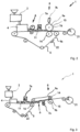
- FIG. 2 A second possible embodiment of a device 1 according to the invention is shown in Figure 2 shown in a simplified representation.
- the goods provided in particular recycled goods, are fed to a processing system 2 via a funnel and processed there into individual fibers and/or fiber bundles.
- the individual fibers and/or fiber bundles are then deposited in a dry forming device 4 on the top of the horizontally extending part of the forming belt 5.
- the fiber mat 10 is slightly pre-compressed by a compression device 6 in front of a moistening device 7a, 7b to 70% of the specific volume of the fiber mat 10 in front of the compression device 6.
- the fiber mat thickness 11 after the compression device 6 is 70% of the fiber mat thickness 11 in front of the compression device 6.
- the individual fibers and / or fiber bundles 12 of the fiber mat 10 are then moistened by a moistening device 7a, 7b.
- the individual fibers and/or fiber bundles 12 of the fiber mat are moistened twice in succession by a moistening device 7a, 7b before they pass through the solidification device 8.
- the second moistening device 7b is formed by the support element 9a designed as a press roller 15 and a water application nozzle, the press roller 15 simultaneously functioning as an application element 7d.
- the two humidification devices 7a, 7b can both be used.
- the surface of the press roller 15 touches the fiber mat 10 directly in a contact area and has a structure or a porous layer for absorbing and storing water, which is applied to the surface through a water application nozzle or, in the case of steam, via a steam application box.
- the water is applied to the top of the fiber mat directly in front of the solidification device 8.
- the fiber mat 10 is fed back into a roll-up.
- the fiber mat 10 formed is laid down in such a way that a very high specific volume of more than 12 cm 3 /g is achieved.
- the amount of water applied is between 5% and 20% of the mass of the laid fiber mat 10.
- the moistening device 7a is followed by a solidification device 8 at a distance.
- the distance is chosen so that as little water as possible can penetrate into the interior of the individual fibers and/or fiber bundles and is available for binding to the surfaces of the individual fibers and/or fiber bundles 12.
- the solidification device 8 follows at the latest after 20 seconds after the application of water.
- the pressing time in the solidification device 8 is less than 1s but more than 0.01ms.
- a further embodiment of the device 1 of the invention is shown in a simplified representation, in which the solidification device 8 is not arranged on the forming belt 5, but in the area of a downstream support element 9a, which is designed as a belt.
- the individual fibers and/or fiber bundles 12 are formed again on the forming belt 5 into a loose fiber mat 10 with a fiber mat thickness 11 and optionally moistened by a moistening device 7a.
- the fiber mat 10 is then removed from the forming belt 5 by a support element 9a designed as a belt removed.
- the rotating, endless belt is guided over a first and a second roller, the second roller functioning as a pressing element 14 in the solidification device 8.
- the support elements 9a, 9b have contact surfaces which are in direct contact with the fiber mat 10. In this example, both contact surfaces are impermeable and designed in such a way that the fiber mat 10 is supported over the entire surface.
- a moistening device 7c can optionally be provided in front of the solidification device 8 in order to apply water to the underside of the fiber mat 10.
- a compression device 6 can again be arranged in front of it.
- the fiber mat 10 formed is laid down in such a way that a very high specific volume of more than 12 cm 3 /g is achieved. In this example, the amount of water applied is between 5% and 20% of the mass of the laid fiber mat 10.
- the moistening device 7a is followed by a solidification device 8 at a distance.
- the distance is chosen so that as little water as possible can penetrate into the interior of the individual fibers and/or fiber bundles and is available for binding to the surfaces of the individual fibers and/or fiber bundles 12.
- the solidification device 8 follows at the latest after 20 seconds after the application of water.
- the pressing time in the solidification device 8 is less than 1s but more than 0.01ms.
- the Figure 4a shows an example of a fiber mat 10 with applied water in cross section in a simplified representation.
- the water can be applied in liquid form or as vapor, which condenses when applied to the fiber mat 10.
- the individual fibers and/or fiber bundles 12 are formed into a fiber mat 10 in a loose fabric in the dry forming device 4 in such a way that the distance between the individual fibers and/or fiber bundles 12 leads to the formation of water drops 13 initially on the surface of the fiber mat 10.
- the solidification step then leads to a distribution of the water applied to the surface of the fiber mat 10 over the fiber mat thickness 11.
- the Figure 4b shows an example of a fiber mat 10 with applied water in a simplified top view.
- the devices 1 of the Figures 1 to 3 are suitable for the continuous production of an endless flat fiber mat 10.
- the Figure 5a shows a first possible variant of a device 1 according to the invention for the discontinuous production process in a simplified representation.
- the flat fiber mat 10 is produced piece by piece as a plate-like product 20. Such products 20 can, for example, be processed into boxes or crates in a further processing step.
- the individual fibers and/or fiber bundles 12 are fed to a dry forming device 4 and laid in a forming mold 17 assigned to the dry forming device 4 to form a piece of fiber mat 10. It is then moistened by a separate moistening device (not shown) and then solidified by pressing with a stamp 18 whose geometry is matched to the forming mold 17.
- the stamp 17 can be heated.
- the stamp comprises an application element 7d having a contact surface. This is connected to the stamp as a porous, compressible layer. After each pressing process, the application element is moistened.
- the stamp 18 and the forming mold 17 together form the solidification device 8 and the application element 7d and the forming mold 17 act as support elements 9a, 9b.
- the Figure 5b shows a second possible variant of a device 1 according to the invention for the discontinuous production process in a simplified representation.
- This device shows a section of the Figure 5a device shown.
- a three-dimensional product 20 is produced in one step.
- the flat fiber mat 10 is formed and solidified in a spatial forming mold 17 to produce a three-dimensional product 20.
- the forming mold 17 and the stamp 18 are adapted to the geometry of the product 20.
- Three-dimensional products 20 can be boxes, crates, etc. or parts thereof.
Landscapes
- Dry Formation Of Fiberboard And The Like (AREA)
- Paper (AREA)
- Nonwoven Fabrics (AREA)
Applications Claiming Priority (3)
| Application Number | Priority Date | Filing Date | Title |
|---|---|---|---|
| DE102018100735 | 2018-01-15 | ||
| PCT/EP2018/081512 WO2019137667A1 (fr) | 2018-01-15 | 2018-11-16 | Procédé et dispositif de fabrication d'une natte en fibres |
| EP18808249.9A EP3740614A1 (fr) | 2018-01-15 | 2018-11-16 | Procédé et dispositif de fabrication d'une natte en fibres |
Related Parent Applications (1)
| Application Number | Title | Priority Date | Filing Date |
|---|---|---|---|
| EP18808249.9A Division EP3740614A1 (fr) | 2018-01-15 | 2018-11-16 | Procédé et dispositif de fabrication d'une natte en fibres |
Publications (1)
| Publication Number | Publication Date |
|---|---|
| EP4345208A2 true EP4345208A2 (fr) | 2024-04-03 |
Family
ID=64477098
Family Applications (2)
| Application Number | Title | Priority Date | Filing Date |
|---|---|---|---|
| EP18808249.9A Pending EP3740614A1 (fr) | 2018-01-15 | 2018-11-16 | Procédé et dispositif de fabrication d'une natte en fibres |
| EP24152005.5A Pending EP4345208A2 (fr) | 2018-01-15 | 2018-11-16 | Procédé et dispositif de fabrication d'une natte en fibres |
Family Applications Before (1)
| Application Number | Title | Priority Date | Filing Date |
|---|---|---|---|
| EP18808249.9A Pending EP3740614A1 (fr) | 2018-01-15 | 2018-11-16 | Procédé et dispositif de fabrication d'une natte en fibres |
Country Status (3)
| Country | Link |
|---|---|
| EP (2) | EP3740614A1 (fr) |
| CN (1) | CN111601927B (fr) |
| WO (1) | WO2019137667A1 (fr) |
Families Citing this family (2)
| Publication number | Priority date | Publication date | Assignee | Title |
|---|---|---|---|---|
| DE102021125451A1 (de) | 2021-09-30 | 2023-03-30 | Voith Patent Gmbh | Verfahren und Maschine zur Herstellung einer Faserstoffbahn in einer Papiermaschine |
| DE102022122488A1 (de) | 2022-09-06 | 2024-03-07 | Voith Patent Gmbh | Vorrichtung zur Herstellung einer Fasermattenbahn und entsprechendes Verfahren |
Citations (1)
| Publication number | Priority date | Publication date | Assignee | Title |
|---|---|---|---|---|
| DE2314893A1 (de) | 1973-03-26 | 1974-10-03 | Kuesters Eduard | Verfahren zur herstellung von blattfoermigen flaechengebilden |
Family Cites Families (7)
| Publication number | Priority date | Publication date | Assignee | Title |
|---|---|---|---|---|
| US4028457A (en) * | 1973-04-16 | 1977-06-07 | Domtar Limited | Consolidation of dry formed webs |
| JPS5230630B2 (fr) * | 1974-07-08 | 1977-08-09 | ||
| US4377543A (en) * | 1981-10-13 | 1983-03-22 | Kimberly-Clark Corporation | Strength and softness control of dry formed sheets |
| DK172928B1 (da) * | 1998-05-01 | 1999-10-04 | Landbrugets Radgvningcenter | Fremgangsmade til fremstilling af enfibermatte,fibermatte samt anvendelse af en sadan fibermatte. |
| WO2012095928A1 (fr) * | 2011-01-12 | 2012-07-19 | セイコーエプソン株式会社 | Système et processus de recyclage de papier |
| DE102011007568A1 (de) * | 2011-04-18 | 2012-10-18 | Voith Patent Gmbh | Vorrichtung und Verfahren zur Herstellung einer Materialbahn |
| DE102011120630A1 (de) * | 2011-12-09 | 2013-06-13 | Aerocycle Gmbh | Verfahren zur Altpapieraufbereitung |
-
2018
- 2018-11-16 EP EP18808249.9A patent/EP3740614A1/fr active Pending
- 2018-11-16 EP EP24152005.5A patent/EP4345208A2/fr active Pending
- 2018-11-16 CN CN201880086474.9A patent/CN111601927B/zh active Active
- 2018-11-16 WO PCT/EP2018/081512 patent/WO2019137667A1/fr unknown
Patent Citations (1)
| Publication number | Priority date | Publication date | Assignee | Title |
|---|---|---|---|---|
| DE2314893A1 (de) | 1973-03-26 | 1974-10-03 | Kuesters Eduard | Verfahren zur herstellung von blattfoermigen flaechengebilden |
Also Published As
| Publication number | Publication date |
|---|---|
| CN111601927B (zh) | 2023-09-08 |
| EP3740614A1 (fr) | 2020-11-25 |
| CN111601927A (zh) | 2020-08-28 |
| WO2019137667A1 (fr) | 2019-07-18 |
Similar Documents
| Publication | Publication Date | Title |
|---|---|---|
| DE69711931T2 (de) | Anlage zur herstellung von einem nicht gewebten faserprodukt | |
| EP2129821B1 (fr) | Système pour traiter des non-tissés | |
| EP2139655B1 (fr) | Production d'éléments non tissés en fibres naturelles | |
| EP1266058A1 (fr) | Procede et dispositif de fabrication de non-tisses composites a l'aide de l'aiguilletage hydrodynamique | |
| WO2018153576A1 (fr) | Procédé et dispositif pour produire une bande de matière fibreuse dans une machine à papier | |
| EP2963167B1 (fr) | Procédé de fabrication de nattes en non tissé, notamment des nattes isolantes et nattes en non tissé obtenues selon ce procédé | |
| EP4345208A2 (fr) | Procédé et dispositif de fabrication d'une natte en fibres | |
| DE102014107725A1 (de) | Verfahren zur Herstellung eines strukturierbaren mehrschichtigen Vlieses und mehrschichtiges Vlies | |
| DE102008057557A1 (de) | Verfahren und Kalibrier- und Verschweißeinheit zur Herstellung von flexiblen Dämm-und/oder Schallschutzplatten oder flexiblem Halbzeug zur Weiterverarbeitung in Heißpressen | |
| DE1461251A1 (de) | Verfahren zum Herstellen eines Vlieses und nach diesem Verfahren hergestelltes Erzeugnis | |
| EP3017105B1 (fr) | Procédé et dispositif pour fabriquer un non-tissé | |
| DE10151368A1 (de) | Fasermatte, daraus hergestelltes Formteil und Verfahren zu dessen Herstellung | |
| DE3325669A1 (de) | Verfahren und vorrichtung zur herstellung von faservliesbahnen | |
| WO2015000685A1 (fr) | Procédé et dispositif de fabrication de non-tissé | |
| DE102005048758A1 (de) | Stabiles Faserlaminat sowie Verfahren und Vorrichtung zur Herstellung desselben | |
| EP3239397B1 (fr) | Procédé et installation de fabrication d'un produit plat en fibres imprégnées | |
| DE2120936C3 (de) | Verfahren zur Herstellung und Aufbereitung von Fasern aus lignozellulosehaltigem Material | |
| DE102007044163A1 (de) | Verfahren zur Herstellung von Dämm- und/oder Schallschutzplatten aus Holzfasern im Trockenverfahren und eine Kalibrier- und Aushärtevorrichtung | |
| DE10004448A1 (de) | Verfahren und Vorrichtung zur Herstellung von Verbundvliesstoffen mittels der hydrodynamischen Vernadelung | |
| DE3518254A1 (de) | Verfahren zur herstellung von rekonstituiertem tabak | |
| WO2015000688A1 (fr) | Procédé et dispositif de fabrication de non-tissé structuré et/ou perforé, en particulier par voie humide | |
| DE19619463A1 (de) | Tiefziehfähiges Material, insbesondere für Verpackungszwecke, und Verfahren zur Herstellung eines derartigen Materials | |
| DE2530661C3 (de) | Verfahren zur Herstellung eines Polsterungsbogens für Verpackungszwecke o.dgl | |
| EP1446080A1 (fr) | Produit plat | |
| DE202024103637U1 (de) | Vorrichtung zur Herstellung einer Faserplatte |
Legal Events
| Date | Code | Title | Description |
|---|---|---|---|
| PUAI | Public reference made under article 153(3) epc to a published international application that has entered the european phase |
Free format text: ORIGINAL CODE: 0009012 |
|
| STAA | Information on the status of an ep patent application or granted ep patent |
Free format text: STATUS: THE APPLICATION HAS BEEN PUBLISHED |
|
| AC | Divisional application: reference to earlier application |
Ref document number: 3740614 Country of ref document: EP Kind code of ref document: P |
|
| AK | Designated contracting states |
Kind code of ref document: A2 Designated state(s): AL AT BE BG CH CY CZ DE DK EE ES FI FR GB GR HR HU IE IS IT LI LT LU LV MC MK MT NL NO PL PT RO RS SE SI SK SM TR |