EP4344595A1 - Beleuchtungseinrichtung für einen staubsauger - Google Patents
Beleuchtungseinrichtung für einen staubsauger Download PDFInfo
- Publication number
- EP4344595A1 EP4344595A1 EP23193689.9A EP23193689A EP4344595A1 EP 4344595 A1 EP4344595 A1 EP 4344595A1 EP 23193689 A EP23193689 A EP 23193689A EP 4344595 A1 EP4344595 A1 EP 4344595A1
- Authority
- EP
- European Patent Office
- Prior art keywords
- lighting device
- lighting
- light exit
- reflector element
- lighting elements
- Prior art date
- Legal status (The legal status is an assumption and is not a legal conclusion. Google has not performed a legal analysis and makes no representation as to the accuracy of the status listed.)
- Granted
Links
Images


Classifications
-
- A—HUMAN NECESSITIES
- A47—FURNITURE; DOMESTIC ARTICLES OR APPLIANCES; COFFEE MILLS; SPICE MILLS; SUCTION CLEANERS IN GENERAL
- A47L—DOMESTIC WASHING OR CLEANING; SUCTION CLEANERS IN GENERAL
- A47L9/00—Details or accessories of suction cleaners, e.g. mechanical means for controlling the suction or for effecting pulsating action; Storing devices specially adapted to suction cleaners or parts thereof; Carrying-vehicles specially adapted for suction cleaners
- A47L9/28—Installation of the electric equipment, e.g. adaptation or attachment to the suction cleaner; Controlling suction cleaners by electric means
- A47L9/2805—Parameters or conditions being sensed
-
- A—HUMAN NECESSITIES
- A47—FURNITURE; DOMESTIC ARTICLES OR APPLIANCES; COFFEE MILLS; SPICE MILLS; SUCTION CLEANERS IN GENERAL
- A47L—DOMESTIC WASHING OR CLEANING; SUCTION CLEANERS IN GENERAL
- A47L9/00—Details or accessories of suction cleaners, e.g. mechanical means for controlling the suction or for effecting pulsating action; Storing devices specially adapted to suction cleaners or parts thereof; Carrying-vehicles specially adapted for suction cleaners
- A47L9/28—Installation of the electric equipment, e.g. adaptation or attachment to the suction cleaner; Controlling suction cleaners by electric means
- A47L9/2857—User input or output elements for control, e.g. buttons, switches or displays
-
- A—HUMAN NECESSITIES
- A47—FURNITURE; DOMESTIC ARTICLES OR APPLIANCES; COFFEE MILLS; SPICE MILLS; SUCTION CLEANERS IN GENERAL
- A47L—DOMESTIC WASHING OR CLEANING; SUCTION CLEANERS IN GENERAL
- A47L9/00—Details or accessories of suction cleaners, e.g. mechanical means for controlling the suction or for effecting pulsating action; Storing devices specially adapted to suction cleaners or parts thereof; Carrying-vehicles specially adapted for suction cleaners
- A47L9/28—Installation of the electric equipment, e.g. adaptation or attachment to the suction cleaner; Controlling suction cleaners by electric means
- A47L9/30—Arrangement of illuminating devices
-
- A—HUMAN NECESSITIES
- A47—FURNITURE; DOMESTIC ARTICLES OR APPLIANCES; COFFEE MILLS; SPICE MILLS; SUCTION CLEANERS IN GENERAL
- A47L—DOMESTIC WASHING OR CLEANING; SUCTION CLEANERS IN GENERAL
- A47L2201/00—Robotic cleaning machines, i.e. with automatic control of the travelling movement or the cleaning operation
Definitions
- the invention relates to a lighting device for a vacuum cleaner for visualizing operating states of the vacuum cleaner, the lighting device having lighting elements, the lighting elements being arranged next to one another in the lighting device in the shape of a ring or ring segment, the lighting device having a reflector element and a light exit element, the reflector element being designed for this purpose to reflect light emitted by the lighting elements in the direction of the light exit element.
- the DE 10 2018 100 904 A1 discloses a vacuum robot with a light ring for visualizing various operating states of the vacuum robot.
- This light ring is formed by a large number of light-emitting diodes, which are arranged in a ring shape directly on the top of the housing.
- the individual light-emitting diodes are clearly visible when switched on and off, so that they do not produce a harmonious lighting behavior with a homogeneous luminance.
- the invention therefore presents the problem of providing a lighting device for a vacuum cleaner which has improved lighting behavior.
- the reflector element forms receptacles in which the lighting elements are arranged, the receptacles of the reflector element shielding the lighting elements from one another.
- the operating states of a vacuum cleaner can be, for example, an error message, a device status or a sensor result. By visualizing operating states, the user should be informed about the current state of the vacuum cleaner in a simple and intuitive way.
- a state can be an internal device status or an external status that results from an interaction between the vacuum cleaner and its environment.
- the lighting elements of the lighting device are preferably LED light-emitting diodes. In alternative embodiments, however, other lighting elements can also be provided in the lighting device.
- the reflector element of the lighting device is designed to reflect light emitted by the lighting elements.
- the reflector element forms this Recordings, in each of which a lighting element of the lighting device is arranged.
- the receptacle of the reflector element is designed and arranged relative to one another in such a way that it shields the individual lighting elements of the lighting device from one another. The recordings thereby prevent the lighting elements from directly illuminating each other.
- the receptacles of the reflector element form side walls which separate the individual lighting elements of the lighting device from one another.
- the receptacles of the reflector element are arranged next to each other in a ring shape or ring segment shape in the lighting device.
- the lighting device according to the invention enables a homogeneous luminance.
- the light exit element is arranged at a distance from the reflector element and the lighting elements on the lighting device.
- a distance of at least four millimeters between the lighting elements and the light exit element is particularly advantageous.
- a distance of at least five millimeters is preferred between the sections of the reflector element which reflect the main component of the light emitted by the lighting elements and the light exit element.
- the spacing between the light exit element and the lighting elements or the reflector element results in the most homogeneous possible illumination of the light entry surface of the light exit element.
- the light exit element is made of a translucent material.
- the degree of translucency is selected so that the light exit element achieves further homogenization of the lighting behavior of the lighting device without significantly reducing its luminosity.
- the light exit element forms a light entry surface and a light exit surface, with a distance between the light entry surface and the light exit surface being larger along the entire cross section in the radial direction than in the axial direction.
- the light entry surface is the surface on which the light emitted by the lighting elements strikes the light exit element.
- the light exit surface is the surface from which the light emitted by the lighting device emerges.
- the distance between the light entry surface is larger in the axial direction than in the axial direction, since more emitted light hits the light entry surface in the radial direction. In order to achieve a homogeneous luminance on the entire exit surface, greater scattering in the light exit element is required in the radial direction.
- the lighting elements are arranged on a circuit board.
- the circuit board is the electronic component for supplying energy and controlling the lighting elements.
- the individual lighting elements of the lighting device are arranged on a common circuit board. This simplifies the assembly process of the lighting device, since all lighting elements can be mounted in the lighting device together with the required electronics in one assembly step.
- the circuit board is designed as an additional reflector element.
- the circuit board is provided with a white print for this purpose. As a result, the light emitted by the lighting elements is reflected back and forth several times between the circuit board and the cover element.
- the lighting device has a housing, with the circuit board being arranged in a bead on an upper side of the housing. This allows a clear placement of the circuit board in relation to the housing of the lighting device. This eliminates a potential source of error during the assembly of the lighting device from the outset.
- the lighting device has a cover element, wherein the cover element is arranged on an upper side of the lighting device, wherein the cover element forms the reflector element.
- the reflector element is ring-shaped or ring-segment-shaped and has indentations along the outer circumference for receiving lighting elements.
- the reflector element is integrated into the cover element of the lighting device in such a way that the reflector element encloses the lighting elements both laterally and from above.
- the indentations in the reflector element are only open in the direction of the light exit element.
- the reflector element forms 12 indentations which are arranged next to one another in a ring shape.
- the lighting device has between 8 and 24 lighting elements, particularly preferably between 12 and 16 lighting elements.
- a comparatively high number of lighting elements enables a uniform luminance of the lighting device along its entire circumference.
- a vacuum cleaner with a lighting device can be both manually operated vacuum cleaners such as floor or stick vacuum cleaners and autonomously operating vacuum cleaners such as vacuum or vacuum mopping robots.
- FIG 1 shows a perspective view of a vacuum robot 12 with a lighting device 10 according to the invention.
- the vacuum robot 12 has a housing 36 with a D-shaped basic shape, which forms a front 38 with a straight housing edge and a back 40 with a rounded housing edge.
- On the front 38 of the vacuum robot 12 is a sensor tower 42 for a lidar sensor (not shown in Figure 1 ) for localization and navigation of the vacuum robot 12 arranged.
- the sensor tower 42 stands up from the housing 36 of the vacuum robot 12 in order to enlarge the detection range of the lidar sensor.
- At the top of the sensor tower 42 there is an annular lighting device 10 for visualizing operating states of the vacuum robot 12.
- the vacuum robot 12 can use this lighting device 10 to communicate error states such as “stuck” or no “dust container inserted” to the user.
- the lighting device 10 can also be used as a direction change indicator or to display distance information about recognized objects.
- a user can be informed about current processes such as a charging or cleaning process via the lighting device 10.
- various other uses are conceivable.
- FIG. 2 shows a sectional view of the lighting device 10.
- the lighting device 10 is arranged on the top 32 of the sensor tower 42 of the vacuum robot 12.
- the housing 28 of the sensor tower 42 forms an annular bead 30 on the top 32.
- the circuit board 26 with the lighting elements 14 inserted thereon is placed in this bead 30.
- the lighting elements 14 are arranged approximately in the middle of the circuit board 26.
- the light exit element 18 is arranged on the circumferential edge of the sensor tower 42, which is fixed in a form-fitting manner by the housing 28 of the sensor tower 42 and the cover element 34 placed on the sensor tower 42 from above.
- the cover element 34 forms the reflector element 16 on the underside, which faces the circuit board 26 in the assembled state.
- the reflector element 16 encloses the lighting elements 14 on the inside, which faces the vertical axis of the sensor tower 42. From the lighting elements 14 in the direction of the vertical Light emitted from the axis of the sensor tower 42 is reflected by the reflector element 16 in the direction of the light exit element 18.
- Figure 3 shows a sectional view of a quarter segment of the lighting device 10 with a reflector element 16, which forms three receptacles 20 for lighting elements 14 in this segment piece.
- the receptacles 20 for the lighting elements 14 are arranged next to each other along a common radius in a ring segment shape.
- the recordings 20 form indentations 48 in which the lighting elements 14 are arranged.
- the indentations 48 are designed so that they completely accommodate the lighting elements 14. As a result, the lighting elements are arranged completely within the indentations 48.
- the lighting elements 14 of the lighting device 10 are completely separated from one another by the side walls 44 of the indentations 48.
- the indentations 48 of the reflector element 16 are open in the direction of the light exit element 18, so that the reflector element 16 reflects the light emitted by the lighting elements 14 in the direction of the light exit element 18.
- the light exit element 18 is arranged at a distance from the lighting elements 14 and the reflector element 16 on the lighting device 10. The distance between the lighting elements 14 and the light exit element 18 prevents the formation of so-called hotspots on the light exit surface of the light exit element 18.
- Figure 4 shows the sectional view of a segment of the lighting device 10 with a reflector element 16, which forms a receptacle 20 for a lighting element 14 in this segment piece.
- the recess 48 is delimited by two side walls 44.
- the recess 48 has a depth 46 of 3.7 millimeters and is thus significantly larger than the arranged lighting element 14.
- the recess 48 extends over an angle 50 of 30 degrees, so that the lighting device 10 has a total of 12 recesses 48 with lighting elements 14.
- the side walls 44 of the reflector element 16 have a rounded shape in order to ensure uniform reflection behavior of the reflector element 16.
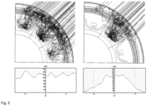
- Figure 5 shows the result of a simulation of the lighting behavior of the lighting device 10 according to the invention.
- the upper left image shows the beam path of the emitted light from three lighting elements 14 arranged adjacent to one another. Below this illustration, a diagram is shown which shows the humanly perceptible brightness curve of the lighting device 10 in the segment shown.
- the reflector element 16 and the light exit element 18 produce a very homogeneous luminance along the entire segment of the lighting device 10.
- the upper right picture of Figure 5 shows the result of a simulation of the lighting behavior of the lighting device 10 with only one activated lighting element 14. In this case, only the centrally arranged lighting element 14 emits light rays, with the two outer lighting elements 14 being deactivated.
- a diagram is shown which shows the humanly perceptible brightness curve of the lighting device 10 in this segment. It can be seen here that, due to the design and arrangement of the reflector element 16 and the light exit element 18, the luminance drops evenly from the illuminated image 20 of the lighting device 10 to the neighboring non-illuminated images 20.
Landscapes
- Engineering & Computer Science (AREA)
- Mechanical Engineering (AREA)
- Arrangement Of Elements, Cooling, Sealing, Or The Like Of Lighting Devices (AREA)
- Electric Vacuum Cleaner (AREA)
Abstract
Description
- Die Erfindung betrifft eine Beleuchtungseinrichtung für einen Staubsauger zur Visualisierung von Betriebszuständen des Staubsaugers, wobei die Beleuchtungseinrichtung Leuchtelemente aufweist, wobei die Leuchtelemente ringförmig oder ringsegmentförmig nebeneinander in der Beleuchtungseinrichtung angeordnet sind, wobei die Beleuchtungseinrichtung ein Reflektorelement und ein Lichtaustrittselement aufweist, wobei das Reflektorelement dazu ausgebildet ist von den Leuchtelementen emittiertes Licht in Richtung des Lichtaustrittselement zu reflektieren.
- Die
DE 10 2018 100 904 A1 offenbart einen Saugroboter mit einem Leuchtring zur Visualisierung verschiedener Betriebszustände des Saugroboters. Dieser Leuchtring wird durch eine Vielzahl an Leuchtdioden gebildet, welche in einer Ringform unmittelbar auf der Gehäuseoberseite angeordnet sind. Die einzelnen Leuchtdioden sind dabei im ein- und ausgeschalteten Zustand eindeutig erkennbar, sodass diese kein harmonisch-wirkendes Leuchtverhalten mit einer homogenen Leuchtdichte erzeugen. Der Erfindung stellt sich somit das Problem eine Beleuchtungseinrichtung für einen Staubsauger zur Verfügung zu stellen, welche ein verbessertes Leuchtverhalten aufweist. - Erfindungsgemäß wird dieses Problem durch ein Beleuchtungseinrichtung mit den Merkmalen von Patentanspruch 1 und durch einen Staubsauger mit den Merkmalen von Patentanspruch 10 gelöst. Erfindungsgemäß bildet das Reflektorelement dazu Aufnahmen aus, in welchen die Leuchtelemente angeordnet sind, wobei die Aufnahmen des Reflektorelementes die Leuchtelemente voneinander abschirmen.
- Bei Betriebszuständen eines Staubsaugers kann es sich dabei beispielsweise um eine Fehlermeldung, einen Geräte-Status oder ein Sensor-Ergebnis handeln. Durch die Visualisierung von Betriebszuständen soll der Benutzer auf einfache und intuitive Weise über einen aktuellen Zustand des Staubsaugers informiert werden. Bei einem solchem Zustand kann es sich dabei, um einen internen Geräte-Status oder um einen externen Status handeln, welcher aus einer Interaktion des Staubsaugers mit seiner Umgebung resultiert.
- Bei den Leuchtelementen der Beleuchtungseinrichtung handelt es sich vorzugsweise um LED-Leuchtdioden. In alternativen Ausführungsformen können aber auch andere Leuchtelemente in der Beleuchtungseinrichtung vorgesehen werden.
- Das Reflektorelement der Beleuchtungseinrichtung ist dazu ausgebildet von den Leuchtelementen emittiertes Licht zu reflektieren. Hierzu bildet das Reflektorelement Aufnahmen aus, in welchen jeweils ein Leuchtelement der Beleuchtungseinrichtung angeordnet ist. Die Aufnahme des Reflektorelementes sind dabei so ausgebildet und zueinander angeordnet, dass diese die einzelnen Leuchtelemente der Beleuchtungseinrichtung voneinander abschirmen. Die Aufnahmen verhindern hierdurch eine direkte gegenseitige Beleuchtung der Leuchtelemente. Die Aufnahmen des Reflektorelementes bilden Seitenwände aus, welche die einzelnen Leuchtelemente der Beleuchtungseinrichtung voneinander separieren. Die Aufnahmen des Reflektorelementes sind dabei nebeneinander ringförmig oder ringsegmentförmig in der Beleuchtungseinrichtung angeordnet. Durch die erfindungsgemäße Beleuchtungseinrichtung wird eine homogene Leuchtdichte ermöglicht.
- Gemäß einer vorteilhaften Ausführungsform ist es bevorzugt, dass das Lichtaustrittselement beabstandet vom dem Reflektorelement und den Leuchtelementen an der Beleuchtungseinrichtung angeordnet ist. Besonders vorteilhaft ist hierbei ein Abstand von mindestens vier Millimetern zwischen den Leuchtelementen und dem Lichtaustrittselement. Zwischen den Abschnitten des Reflektorelementes, welche den Hauptbestandteil des emittierten Lichts der Leuchtelemente reflektieren und dem Lichtaustrittelement ist ein Abstand von mindestens fünf Millimetern bevorzugt. Die Beabstandung zwischen dem Lichtaustrittselement und den Leuchtelementen respektive dem Reflektorelement resultiert in einer schon möglichst homogenen Beleuchtung der Lichteintrittsfläche des Lichtaustrittselementes.
- In einer weiteren Ausführungsform ist es bevorzugt, dass das Lichtaustrittselement aus einem transluzenten Material ausgebildet ist. Der Grad der Transluzenz ist dabei so gewählt, dass das Lichtaustrittselement eine weitere Homogenisierung des Leuchtverhaltens der Beleuchtungseinrichtung erreicht, ohne dessen Leuchtstärke im signifikanten Umfang zu reduzieren.
- Bevorzugt ist, dass das Lichtaustrittselement eine Lichteintrittsfläche und eine Lichtaustrittsfläche ausbildet, wobei ein Abstand zwischen der Lichteintrittsfläche und der Lichtaustrittsfläche entlang des gesamten Querschnitts in radialer Richtung größer ausgebildet ist als in axialer Richtung. Die Lichteintrittsfläche ist dabei die Fläche, auf welche das von den Leuchtelementen emittierte Licht in das Lichtaustrittselement auftrifft. Die Lichtaustrittsfläche ist die Fläche, aus welcher das von der Beleuchtungseinrichtung emittierte Licht austritt. Der Abstand zwischen Lichteintrittsfläche ist in axialer Richtung größer als in axialer Richtung, da in radialer Richtung mehr emittiertes Licht auf die Lichteintrittsfläche auftrifft. Zur Erreichung einer homogenen Leuchtdichte auf der gesamten Austrittsfläche bedarf es daher in radialer Richtung eine stärkere Streuung im Lichtaustrittselement.
- Zudem ist es bevorzugt, dass die Leuchtelemente auf einer Leiterplatte angeordnet sind. Die Leiterplatte ist das elektronische Bauteil zur Energieversorgung und Steuerung der Leuchtelemente. Die einzelnen Leuchtelemente der Beleuchtungseinrichtung sind dabei auf einer gemeinsamen Leiterplatte angeordnet. Hierdurch wird der Montageprozess der Beleuchtungseinrichtung vereinfacht, da alle Leuchtelemente zusammen mit der erforderlichen Elektronik in einem Montageschritt in der Beleuchtungseinrichtung montiert werden können.
- Weiterhin ist es bevorzugt, dass die Leiterplatte als zusätzliches Reflektorelement ausgebildet ist. In einer vorteilhaften Ausführungsform ist die Leiterplatte hierzu mit einem weißen Aufdruck versehen. Hierdurch wird das von den Leuchtelementen emittiertes Licht mehrfach zwischen Leiterplatte und Deckelelement hin und her reflektiert.
- In einer alternativen Ausführungsform ist es bevorzugt, dass die Beleuchtungseinrichtung ein Gehäuse aufweist, wobei die Leiterplatte in einer Sicke auf einer Oberseite des Gehäuses angeordnet ist. Dies erlaubt eine eindeutige Platzierung der Leiterplatte in Bezug auf das Gehäuse der Beleuchtungseinrichtung. Hierdurch wird eine potenzielle Fehlerquelle im Rahmen der Montage der Beleuchtungseinrichtung von vorneherein ausgeschlossen.
- Weiterhin ist es bevorzugt, dass die Beleuchtungseinrichtung einen Deckelelement aufweist, wobei das Deckelelement auf einer Oberseite der Beleuchtungseinrichtung angeordnet ist, wobei das Deckelelement das Reflektorelement ausbildet. Das Reflektorelement ist ringförmig oder ringsegmentförmig ausgebildet und weist entlang des äußeren Umfangs Einbuchtungen zur Aufnahme von Leuchtelementen auf. Das Reflektorelement ist dabei so in das Deckelelement der Beleuchtungseinrichtung integriert, dass das Reflektorelement die Leuchtelemente sowohl seitlich als auch von oben umschließt. Die Einbuchtungen im Reflektorelement sind lediglich in Richtung des Lichtaustrittselementes geöffnet. In einer besonders bevorzugten Ausführungsform bildet das Reflektorelement 12 Einbuchtungen aus, welche ringförmig nebeneinander angeordnet sind. Die Integration des Reflektorelementes mit dem Deckelelement vereinfacht den Aufbau der Beleuchtungseinrichtung und reduziert hierdurch dessen Montageaufwand.
- Es ist bevorzugt, dass die Beleuchtungseinrichtung zwischen 8 und 24 Leuchtelemente, besonders bevorzugt zwischen 12 und 16 Leuchtelemente, aufweist. Eine vergleichsweise hohe Anzahl an Leuchtelementen ermöglicht eine gleichmäßige Leuchtdichte der Beleuchtungseinrichtung entlang deren gesamten Umfangs.
- Bei einem Staubsauger mit einer erfindungsgemäßen Beleuchtungseinrichtung kann es sich sowohl um manuell geführte Staubsauger wie Boden- oder Stickstaubsauger als auch um autonom agierende Staubsauger wie Saug- oder Saugwischroboter handeln.
- Ein Ausführungsbeispiel der Erfindung ist in den Zeichnungen rein schematisch dargestellt und wird nachfolgend näher beschrieben. Es zeigen:
- Figur 1
- Perspektivische Ansicht eines Saugroboters mit einer Beleuchtungseinrichtung;
- Figur 2
- Schnittansicht der Beleuchtungseinrichtung;
- Figur 3
- Schnittansicht eines Abschnitts der Beleuchtungseinrichtung;
- Figur 4
- Schnittansicht eines Segments der Beleuchtungseinrichtung;
- Figur 5
- Darstellung des Leuchtverhaltens der Beleuchtungseinrichtung
-
Figur 1 zeigt eine perspektivische Ansicht eines Saugroboters 12 mit einer erfindungsgemäßen Beleuchtungseinrichtung 10. Der Saugroboter 12 verfügt über ein Gehäuse 36 mit einer D-förmigen Grundform, welche eine Vorderseite 38 mit einer geraden Gehäusekante und eine Rückseite 40 mit einer abgerundeten Gehäusekante ausbildet. An der Vorderseite 38 des Saugroboters 12 ist ein Sensorturm 42 für einen Lidar-Sensor (nicht gezeigt inFigur 1 ) zur Lokalisation und Navigation des Saugroboters 12 angeordnet. Der Sensorturm 42 steht dabei vom Gehäuse 36 des Saugroboters 12 empor, um den Erfassungsbereich des Lidar-Sensors zu vergrößern. Auf der Spitze des Sensorturms 42 ist eine ringförmige Beleuchtungseinrichtung 10 zur Visualisierung von Betriebszuständen des Saugroboters 12 angeordnet. Über diese Beleuchtungseinrichtung 10 kann der Saugroboter 12 beispielweise Fehlerzustände wie "Festgefahren" oder kein "Staubbehälter eingesetzt" an den Benutzer kommunizieren. Die Beleuchtungseinrichtung 10 kann aber auch dazu eingesetzt werden als Fahrtrichtungswechselanzeige oder zur Wiedergabe von Abstandsinformationen zu erkannten Objekten eingesetzt werden. Zudem kann ein Benutzer über die Beleuchtungseinrichtung 10 über aktuelle Prozesse wie einen Lade- oder einen Reinigungsvorgang informiert werden. Neben den aufgeführten Anwendungsbeispielen für die Beleuchtungseinrichtung 10 sind diverse andere Verwendungszwecke denkbar. -
Figur 2 zeigt eine Schnittansicht der Beleuchtungseinrichtung 10. Die Beleuchtungseinrichtung 10 ist dabei auf der Oberseite 32 des Sensorturms 42 des Saugroboters 12 angeordnet. Hierzu bildet das Gehäuse 28 des Sensorturms 42 auf der Oberseite 32 eine ringförmige Sicke 30 aus. In diese Sicke 30 ist die Leiterplatte 26 mit denen darauf eingesetzten Leuchtelementen 14 platziert. Die Leuchtelemente 14 sind dabei annähernd mittig auf der Leiterplatte 26 angeordnet. Am umlaufenden Rand des Sensorturms 42 ist das Lichtaustrittselement 18 angeordnet, welches formschlüssig durch das Gehäuse 28 des Sensorturms 42 und das von oben auf den Sensorturm 42 aufgesetzte Deckelelement 34 fixiert wird. Das Deckelelement 34 bildet auf der Unterseite, welche im montierten Zustand der Leiterplatte 26 zugewandt ist, das Reflektorelement 16 aus. Wie in der Schnittansicht vonFigur 2 gezeigt, umschließt das Reflektorelement 16 die Leuchtelemente 14 an deren Innenseite, welche der vertikalen Achse des Sensorturms 42 zugewandt ist. Von den Leuchtelementen 14 in Richtung der vertikalen Achse des Sensorturms 42 emittiertes Licht wird durch das Reflektorelement 16 in Richtung des Lichtaustrittselementes 18 reflektiert. -
Figur 3 zeigt eine Schnittansicht eines Viertelsegments der Beleuchtungseinrichtung 10 mit einem Reflektorelement 16, welches in diesem Segmentstück drei Aufnahmen 20 für Leuchtelemente 14 ausbildet. Die Aufnahmen 20 für die Leuchtelemente 14 sind dabei nebeneinander entlang eines gemeinsamen Radius in einer Ringsegment-Form angeordnet. Die Aufnahmen 20 bilden dabei Einbuchtungen 48 aus, in welchen die Leuchtelemente 14 angeordnet sind. Die Einbuchtungen 48 sind dabei so ausgeführt, dass diese die Leuchtelemente 14 vollständig aufnehmen. Hierdurch sind die Leuchtelemente vollständig innerhalb der Einbuchtungen 48 angeordnet. Die Leuchtelemente 14 der Beleuchtungseinrichtung 10 werden durch die Seitenwände 44 der Einbuchtungen 48 vollständig voneinander getrennt. Zwischen den Seitenwänden 44 der Einbuchtungen 48 und dem Lichtaustrittselement 18 besteht eine Lücke, diese ist aber so ausgebildet, dass hierdurch nur zuvor reflektiertes Licht passieren kann. Eine direkte gegenseitige Beleuchtung der Leuchtelemente 14 wird durch die Seitenwände der Einbuchtungen verhindert. Die Einbuchtungen 48 des Reflektorelementes 16 sind in Richtung des Lichtaustrittselements 18 geöffnet, sodass das Reflektorelement 16 das von den Leuchtelementen 14 emittierte Licht in Richtung des Lichtaustrittselementes 18 reflektiert. Das Lichtaustrittselement 18 ist beabstandet von den Leuchtelementen 14 und dem Reflektorelement 16 an der Beleuchtungseinrichtung 10 angeordnet. Der Abstand zwischen den Leuchtelementen 14 und dem Lichtaustrittselement 18 verhindert das Bilden von sogenannten Hotspots auf der Lichtaustrittsfläche des Lichtaustrittselementes 18. -
Figur 4 zeigt die Schnittansicht eines Segments der Beleuchtungseinrichtung 10 mit einem Reflektorelement 16, welches in diesem Segmentstück eine Aufnahme 20 für ein Leuchtelement 14 ausbildet. Die Einbuchtung 48 wird durch zwei Seitenwände 44 begrenzt. Die Einbuchtung 48 weist eine Tiefe 46 von 3,7 Millimetern auf und ist somit deutlich größer als das angeordnete Leuchtelement 14. Die Einbuchtung 48 erstreckt sich über einen Winkel 50 von 30 Grad, sodass die Beleuchtungseinrichtung 10 in Summe 12 Einbuchtungen 48 mit Leuchtelementen 14 aufweist. Die Seitenwände 44 des Reflektorelementes 16 verfügen über eine abgerundete Formgebung, um ein gleichmäßiges Reflexionsverhalten des Reflektorelementes 16 zu gewährleisten. -
Figur 5 zeigt das Ergebnis einer Simulation des Leuchtverhaltens der erfindungsgemäßen Beleuchtungseinrichtung 10. Im oberen linken Bild wird der Strahlengang des emittierten Lichts von drei benachbart zueinander angeordneten Leuchtelementen 14 angezeigt. Unterhalb dieser Darstellung ist ein Diagramm gezeigt, welches den menschlich wahrnehmbaren Helligkeitsverlauf der Beleuchtungseinrichtung 10 in dem dargestellten Segment aufzeigt. - Hierbei wird ersichtlich, dass das Reflektorelement 16 und das Lichtaustrittselement 18 eine sehr homogene Leuchtdichte entlang des gesamten Segments der Beleuchtungseinrichtung 10 bewirken.
- Das obere rechte Bild von
Figur 5 zeigt das Ergebnis einer Simulation des Leuchtverhaltens der Beleuchtungseinrichtung 10 mit nur einem aktivierten Leuchtelement 14. Hierbei emittiert nur das mittig angeordnete Leuchtelement 14 Lichtstrahlen, wobei die beiden äußeren Leuchtelemente 14 deaktiviert sind. Unterhalb dieser Darstellung ist ein Diagramm gezeigt, welches den menschlich wahrnehmbaren Helligkeitsverlauf der Beleuchtungseinrichtung 10 in diesem Segment aufzeigt. Hierbei wird ersichtlich, dass infolge der Ausgestaltung und Anordnung des Reflektorelementes 16 und des Lichtaustrittelementes 18 die Leuchtdichte ausgehend von der beleuchteten Aufnahme 20 der Beleuchtungseinrichtung 10 zu den benachbarten nicht beleuchteten Aufnahmen 20 gleichmäßig abfällt. -
- 10
- Beleuchtungseinrichtung
- 12
- Staubsauger / Saugroboter
- 14
- Leuchtelement
- 16
- Reflektorelement
- 18
- Lichtaustrittselement
- 20
- Aufnahme
- 22
- Lichteintrittsfläche
- 24
- Lichtaustrittsfläche
- 26
- Leiterplatte
- 28
- Gehäuse
- 30
- Sicke
- 32
- Oberseite
- 34
- Deckelelement
- 36
- Gehäuse Saugroboter
- 38
- Vorderseite Saugroboter
- 40
- Rückseite Saugroboter
- 42
- Sensorturm
- 44
- Seitenwände
- 46
- Tiefe Einbuchtung
- 48
- Einbuchtung
- 50
- Winkel Einbuchtung
Claims (11)
- Beleuchtungseinrichtung (10) für einen Staubsauger (12) zur Visualisierung von Betriebszuständen des Staubsaugers, wobei die Beleuchtungseinrichtung Leuchtelemente (14) aufweist, wobei die Leuchtelemente ringförmig oder ringsegmentförmig nebeneinander in der Beleuchtungseinrichtung angeordnet sind, wobei die Beleuchtungseinrichtung ein Reflektorelement (16) und ein Lichtaustrittselement (18) aufweist, wobei das Reflektorelement dazu ausgebildet ist von den Leuchtelementen emittiertes Licht in Richtung des Lichtaustrittselement zu reflektieren,
dadurch gekennzeichnet,
dass das Reflektorelement Aufnahmen (20) ausbildet, wobei in den Aufnahmen die Leuchtelemente angeordnet sind, wobei die Aufnahmen des Reflektorelementes die Leuchtelemente voneinander abschirmen. - Beleuchtungseinrichtung (10) nach einem der vorhergehenden Ansprüche,
dadurch gekennzeichnet,
dass das Lichtaustrittselement (18) beabstandet vom dem Reflektorelement (16) und den Leuchtelementen (14) an der Beleuchtungseinrichtung angeordnet ist. - Beleuchtungseinrichtung (10) nach einem der vorhergehenden Ansprüche,
dadurch gekennzeichnet,
dass das Reflektorelement (16) einen Abstand von mindesten 1,5 Millimetern zum Lichtaustrittselement (18) aufweist. - Beleuchtungseinrichtung (10) nach Anspruch 3,
dadurch gekennzeichnet,
dass das Lichtaustrittselement (18) aus einem transluzenten Material ausgebildet ist. - Beleuchtungseinrichtung (10) nach einem der vorhergehenden Ansprüche,
dadurch gekennzeichnet,
dass das Lichtaustrittselement (18) eine Lichteintrittsfläche (22) und eine Lichtaustrittsfläche (24) ausbildet, wobei ein Abstand zwischen der Lichteintrittsfläche und der Lichtaustrittsfläche entlang des gesamten Querschnitts in radialer Richtung größer ausgebildet ist als in axialer Richtung. - Beleuchtungseinrichtung (10) nach einem der vorhergehenden Ansprüche,
dadurch gekennzeichnet,
dass die Leuchtelemente (14) auf einer Leiterplatte (26) angeordnet sind. - Beleuchtungseinrichtung (10) nach Anspruch 6,
dadurch gekennzeichnet,
dass die Leiterplatte (26) als zusätzliches Reflektorelement ausgebildet ist. - Beleuchtungseinrichtung (10) nach einem der vorhergehenden Ansprüche,
dadurch gekennzeichnet,
dass die Beleuchtungseinrichtung ein Gehäuse (28) aufweist, wobei die Leiterplatte (26) in einer Sicke (30) auf einer Oberseite (32) des Gehäuses (28) angeordnet ist. - Beleuchtungseinrichtung (10) nach einem der vorhergehenden Ansprüche,
dadurch gekennzeichnet,
dass die Beleuchtungseinrichtung einen Deckelelement (34) aufweist, wobei das Deckelelement auf einer Oberseite der Beleuchtungseinrichtung angeordnet ist, wobei das Deckelelement das Reflektorelement (16) ausbildet. - Beleuchtungseinrichtung (10) nach einem der vorhergehenden Ansprüche,
dadurch gekennzeichnet,
dass die Beleuchtungseinrichtung zwischen 8 und 24 Leuchtelemente (14), besonders bevorzugt zwischen 12 und 16 Leuchtelemente, aufweist. - Staubsauger (12), insbesondere Saugroboter, mit einer Beleuchtungseinrichtung (10) nach Anspruch 1.
Applications Claiming Priority (1)
| Application Number | Priority Date | Filing Date | Title |
|---|---|---|---|
| BE20225777A BE1030924B1 (de) | 2022-09-29 | 2022-09-29 | Beleuchtungseinrichtung für einen Staubsauger |
Publications (3)
| Publication Number | Publication Date |
|---|---|
| EP4344595A1 true EP4344595A1 (de) | 2024-04-03 |
| EP4344595C0 EP4344595C0 (de) | 2025-02-19 |
| EP4344595B1 EP4344595B1 (de) | 2025-02-19 |
Family
ID=85157459
Family Applications (1)
| Application Number | Title | Priority Date | Filing Date |
|---|---|---|---|
| EP23193689.9A Active EP4344595B1 (de) | 2022-09-29 | 2023-08-28 | Beleuchtungseinrichtung für einen staubsauger |
Country Status (2)
| Country | Link |
|---|---|
| EP (1) | EP4344595B1 (de) |
| BE (1) | BE1030924B1 (de) |
Citations (2)
| Publication number | Priority date | Publication date | Assignee | Title |
|---|---|---|---|---|
| DE102018100904A1 (de) | 2018-01-17 | 2019-07-18 | Miele & Cie. Kg | Saugroboter und Verfahren zum Betrieb eines Saugroboters |
| US20200138260A1 (en) * | 2018-11-07 | 2020-05-07 | Sharkninja Operating, Llc | Illuminator optic for robotic cleaner |
-
2022
- 2022-09-29 BE BE20225777A patent/BE1030924B1/de not_active IP Right Cessation
-
2023
- 2023-08-28 EP EP23193689.9A patent/EP4344595B1/de active Active
Patent Citations (2)
| Publication number | Priority date | Publication date | Assignee | Title |
|---|---|---|---|---|
| DE102018100904A1 (de) | 2018-01-17 | 2019-07-18 | Miele & Cie. Kg | Saugroboter und Verfahren zum Betrieb eines Saugroboters |
| US20200138260A1 (en) * | 2018-11-07 | 2020-05-07 | Sharkninja Operating, Llc | Illuminator optic for robotic cleaner |
Also Published As
| Publication number | Publication date |
|---|---|
| EP4344595C0 (de) | 2025-02-19 |
| BE1030924A1 (de) | 2024-04-23 |
| EP4344595B1 (de) | 2025-02-19 |
| BE1030924B1 (de) | 2024-04-29 |
Similar Documents
| Publication | Publication Date | Title |
|---|---|---|
| DE102012112151B4 (de) | Kraftfahrzeugrückleuchte mit zumindest einer Schlusslichtfunktion, einer Blinklichtfunktion und einer Bremslichtfunktion, die einen ersten und mindestens einen zweiten Lichtleiter umfasst | |
| DE4339738C2 (de) | Codierer | |
| DE102004042915B4 (de) | Leuchte zur Ausleuchtung von Gebäudeflächen oder Gebäudeteilflächen | |
| DE102011055973B4 (de) | Anzeigevorrichtung eines Getriebes eines Fahrzeuges | |
| DE102016221918A1 (de) | Beleuchtungsvorrichtung, insbesondere für ein Kraftfahrzeug | |
| DE102021116722A1 (de) | Beleuchtungsvorrichtung eines kühlergrills für ein automobil | |
| DE102007042069A1 (de) | Bedienungspultanordnung für eine Wäschemaschine | |
| DE102008042472A1 (de) | Leuchtring | |
| WO2006007903A1 (de) | Differential für eine fahrzeugachse | |
| DE102005042143B4 (de) | Entfernbare Markierungsvorrichtung für eine Form | |
| EP4001854A1 (de) | Sensor | |
| EP4344595B1 (de) | Beleuchtungseinrichtung für einen staubsauger | |
| EP0770202A1 (de) | Beleuchtete anzeigevorrichtung und beleuchteter zeiger | |
| DE102008008531A1 (de) | Unterflurzeiger mit passivem Leuchtkörper | |
| DE102020113177A1 (de) | Beleuchtungsvorrichtung für den Innenraum eines Kraftfahrzeugs | |
| DE10230023C5 (de) | Optischer Signalgeber, insbesondere für die Bedienblende eines Haushaltsgroßgerätes | |
| DE10341219A1 (de) | Leuchte zur Anbringung an einer Gebäudefläche oder Gebäudeteilfläche | |
| DE202013101815U1 (de) | Anordnung zur Lichtabgabe mit einer LED-Lichtquelle und einem Reflektor | |
| DE112018001994B4 (de) | Schrittmotor und Anzeigeeinrichtungsinstrument für ein Fahrzeug | |
| DE102020121803A1 (de) | Kraftfahrzeug mit einem Kühlergrill | |
| DE10153756A1 (de) | Leuchte mit segmentiertem Innenreflektor | |
| WO2023072555A1 (de) | Kraftfahrzeugbeleuchtungsmodul | |
| DE60019523T2 (de) | Beleuchtbares Zeigerinstrument | |
| WO2023280639A1 (de) | Beleuchtungsvorrichtung für ein kraftfahrzeug | |
| DE202017103188U1 (de) | Optische Anordnung für eine Lichtquelle |
Legal Events
| Date | Code | Title | Description |
|---|---|---|---|
| PUAI | Public reference made under article 153(3) epc to a published international application that has entered the european phase |
Free format text: ORIGINAL CODE: 0009012 |
|
| STAA | Information on the status of an ep patent application or granted ep patent |
Free format text: STATUS: THE APPLICATION HAS BEEN PUBLISHED |
|
| AK | Designated contracting states |
Kind code of ref document: A1 Designated state(s): AL AT BE BG CH CY CZ DE DK EE ES FI FR GB GR HR HU IE IS IT LI LT LU LV MC ME MK MT NL NO PL PT RO RS SE SI SK SM TR |
|
| STAA | Information on the status of an ep patent application or granted ep patent |
Free format text: STATUS: REQUEST FOR EXAMINATION WAS MADE |
|
| 17P | Request for examination filed |
Effective date: 20241004 |
|
| RBV | Designated contracting states (corrected) |
Designated state(s): AL AT BE BG CH CY CZ DE DK EE ES FI FR GB GR HR HU IE IS IT LI LT LU LV MC ME MK MT NL NO PL PT RO RS SE SI SK SM TR |
|
| GRAP | Despatch of communication of intention to grant a patent |
Free format text: ORIGINAL CODE: EPIDOSNIGR1 |
|
| STAA | Information on the status of an ep patent application or granted ep patent |
Free format text: STATUS: GRANT OF PATENT IS INTENDED |
|
| INTG | Intention to grant announced |
Effective date: 20241120 |
|
| GRAS | Grant fee paid |
Free format text: ORIGINAL CODE: EPIDOSNIGR3 |
|
| GRAA | (expected) grant |
Free format text: ORIGINAL CODE: 0009210 |
|
| STAA | Information on the status of an ep patent application or granted ep patent |
Free format text: STATUS: THE PATENT HAS BEEN GRANTED |
|
| AK | Designated contracting states |
Kind code of ref document: B1 Designated state(s): AL AT BE BG CH CY CZ DE DK EE ES FI FR GB GR HR HU IE IS IT LI LT LU LV MC ME MK MT NL NO PL PT RO RS SE SI SK SM TR |
|
| REG | Reference to a national code |
Ref country code: GB Ref legal event code: FG4D Free format text: NOT ENGLISH |
|
| REG | Reference to a national code |
Ref country code: CH Ref legal event code: EP |
|
| REG | Reference to a national code |
Ref country code: IE Ref legal event code: FG4D Free format text: LANGUAGE OF EP DOCUMENT: GERMAN |
|
| REG | Reference to a national code |
Ref country code: DE Ref legal event code: R096 Ref document number: 502023000587 Country of ref document: DE |
|
| U01 | Request for unitary effect filed |
Effective date: 20250219 |
|
| U07 | Unitary effect registered |
Designated state(s): AT BE BG DE DK EE FI FR IT LT LU LV MT NL PT RO SE SI Effective date: 20250225 |
|
| REG | Reference to a national code |
Ref country code: GB Ref legal event code: 746 Effective date: 20250521 |
|
| PG25 | Lapsed in a contracting state [announced via postgrant information from national office to epo] |
Ref country code: RS Free format text: LAPSE BECAUSE OF FAILURE TO SUBMIT A TRANSLATION OF THE DESCRIPTION OR TO PAY THE FEE WITHIN THE PRESCRIBED TIME-LIMIT Effective date: 20250519 |
|
| PG25 | Lapsed in a contracting state [announced via postgrant information from national office to epo] |
Ref country code: PL Free format text: LAPSE BECAUSE OF FAILURE TO SUBMIT A TRANSLATION OF THE DESCRIPTION OR TO PAY THE FEE WITHIN THE PRESCRIBED TIME-LIMIT Effective date: 20250219 |
|
| PG25 | Lapsed in a contracting state [announced via postgrant information from national office to epo] |
Ref country code: ES Free format text: LAPSE BECAUSE OF FAILURE TO SUBMIT A TRANSLATION OF THE DESCRIPTION OR TO PAY THE FEE WITHIN THE PRESCRIBED TIME-LIMIT Effective date: 20250219 |
|
| PG25 | Lapsed in a contracting state [announced via postgrant information from national office to epo] |
Ref country code: IS Free format text: LAPSE BECAUSE OF FAILURE TO SUBMIT A TRANSLATION OF THE DESCRIPTION OR TO PAY THE FEE WITHIN THE PRESCRIBED TIME-LIMIT Effective date: 20250619 Ref country code: NO Free format text: LAPSE BECAUSE OF FAILURE TO SUBMIT A TRANSLATION OF THE DESCRIPTION OR TO PAY THE FEE WITHIN THE PRESCRIBED TIME-LIMIT Effective date: 20250519 |
|
| PG25 | Lapsed in a contracting state [announced via postgrant information from national office to epo] |
Ref country code: HR Free format text: LAPSE BECAUSE OF FAILURE TO SUBMIT A TRANSLATION OF THE DESCRIPTION OR TO PAY THE FEE WITHIN THE PRESCRIBED TIME-LIMIT Effective date: 20250219 |
|
| PG25 | Lapsed in a contracting state [announced via postgrant information from national office to epo] |
Ref country code: GR Free format text: LAPSE BECAUSE OF FAILURE TO SUBMIT A TRANSLATION OF THE DESCRIPTION OR TO PAY THE FEE WITHIN THE PRESCRIBED TIME-LIMIT Effective date: 20250520 |
|
| PG25 | Lapsed in a contracting state [announced via postgrant information from national office to epo] |
Ref country code: SM Free format text: LAPSE BECAUSE OF FAILURE TO SUBMIT A TRANSLATION OF THE DESCRIPTION OR TO PAY THE FEE WITHIN THE PRESCRIBED TIME-LIMIT Effective date: 20250219 |
|
| U20 | Renewal fee for the european patent with unitary effect paid |
Year of fee payment: 3 Effective date: 20250901 |
|
| PG25 | Lapsed in a contracting state [announced via postgrant information from national office to epo] |
Ref country code: CZ Free format text: LAPSE BECAUSE OF FAILURE TO SUBMIT A TRANSLATION OF THE DESCRIPTION OR TO PAY THE FEE WITHIN THE PRESCRIBED TIME-LIMIT Effective date: 20250219 |
|
| PG25 | Lapsed in a contracting state [announced via postgrant information from national office to epo] |
Ref country code: SK Free format text: LAPSE BECAUSE OF FAILURE TO SUBMIT A TRANSLATION OF THE DESCRIPTION OR TO PAY THE FEE WITHIN THE PRESCRIBED TIME-LIMIT Effective date: 20250219 |
|
| PLBE | No opposition filed within time limit |
Free format text: ORIGINAL CODE: 0009261 |
|
| STAA | Information on the status of an ep patent application or granted ep patent |
Free format text: STATUS: NO OPPOSITION FILED WITHIN TIME LIMIT |
|
| 26N | No opposition filed |
Effective date: 20251120 |
|
| PG25 | Lapsed in a contracting state [announced via postgrant information from national office to epo] |
Ref country code: MC Free format text: LAPSE BECAUSE OF FAILURE TO SUBMIT A TRANSLATION OF THE DESCRIPTION OR TO PAY THE FEE WITHIN THE PRESCRIBED TIME-LIMIT Effective date: 20250219 |
|
| PG25 | Lapsed in a contracting state [announced via postgrant information from national office to epo] |
Ref country code: IE Free format text: LAPSE BECAUSE OF NON-PAYMENT OF DUE FEES Effective date: 20250828 |