EP4339381A1 - Wasserstoppmechanismus für wasserauslassvorrichtung und wasserauslassvorrichtung - Google Patents
Wasserstoppmechanismus für wasserauslassvorrichtung und wasserauslassvorrichtung Download PDFInfo
- Publication number
- EP4339381A1 EP4339381A1 EP22211494.4A EP22211494A EP4339381A1 EP 4339381 A1 EP4339381 A1 EP 4339381A1 EP 22211494 A EP22211494 A EP 22211494A EP 4339381 A1 EP4339381 A1 EP 4339381A1
- Authority
- EP
- European Patent Office
- Prior art keywords
- water outlet
- water
- pad members
- outlet device
- pad
- Prior art date
- Legal status (The legal status is an assumption and is not a legal conclusion. Google has not performed a legal analysis and makes no representation as to the accuracy of the status listed.)
- Pending
Links
Images


Classifications
-
- B—PERFORMING OPERATIONS; TRANSPORTING
- B05—SPRAYING OR ATOMISING IN GENERAL; APPLYING FLUENT MATERIALS TO SURFACES, IN GENERAL
- B05B—SPRAYING APPARATUS; ATOMISING APPARATUS; NOZZLES
- B05B1/00—Nozzles, spray heads or other outlets, with or without auxiliary devices such as valves, heating means
- B05B1/14—Nozzles, spray heads or other outlets, with or without auxiliary devices such as valves, heating means with multiple outlet openings; with strainers in or outside the outlet opening
- B05B1/16—Nozzles, spray heads or other outlets, with or without auxiliary devices such as valves, heating means with multiple outlet openings; with strainers in or outside the outlet opening having selectively- effective outlets
-
- E—FIXED CONSTRUCTIONS
- E03—WATER SUPPLY; SEWERAGE
- E03C—DOMESTIC PLUMBING INSTALLATIONS FOR FRESH WATER OR WASTE WATER; SINKS
- E03C1/00—Domestic plumbing installations for fresh water or waste water; Sinks
- E03C1/02—Plumbing installations for fresh water
- E03C1/04—Water-basin installations specially adapted to wash-basins or baths
- E03C1/0408—Water installations especially for showers
-
- B—PERFORMING OPERATIONS; TRANSPORTING
- B05—SPRAYING OR ATOMISING IN GENERAL; APPLYING FLUENT MATERIALS TO SURFACES, IN GENERAL
- B05B—SPRAYING APPARATUS; ATOMISING APPARATUS; NOZZLES
- B05B1/00—Nozzles, spray heads or other outlets, with or without auxiliary devices such as valves, heating means
- B05B1/14—Nozzles, spray heads or other outlets, with or without auxiliary devices such as valves, heating means with multiple outlet openings; with strainers in or outside the outlet opening
- B05B1/18—Roses; Shower heads
- B05B1/185—Roses; Shower heads characterised by their outlet element; Mounting arrangements therefor
-
- B—PERFORMING OPERATIONS; TRANSPORTING
- B05—SPRAYING OR ATOMISING IN GENERAL; APPLYING FLUENT MATERIALS TO SURFACES, IN GENERAL
- B05B—SPRAYING APPARATUS; ATOMISING APPARATUS; NOZZLES
- B05B1/00—Nozzles, spray heads or other outlets, with or without auxiliary devices such as valves, heating means
- B05B1/30—Nozzles, spray heads or other outlets, with or without auxiliary devices such as valves, heating means designed to control volume of flow, e.g. with adjustable passages
- B05B1/3006—Nozzles, spray heads or other outlets, with or without auxiliary devices such as valves, heating means designed to control volume of flow, e.g. with adjustable passages the controlling element being actuated by the pressure of the fluid to be sprayed
-
- E—FIXED CONSTRUCTIONS
- E03—WATER SUPPLY; SEWERAGE
- E03C—DOMESTIC PLUMBING INSTALLATIONS FOR FRESH WATER OR WASTE WATER; SINKS
- E03C1/00—Domestic plumbing installations for fresh water or waste water; Sinks
- E03C1/02—Plumbing installations for fresh water
- E03C1/04—Water-basin installations specially adapted to wash-basins or baths
- E03C1/0408—Water installations especially for showers
- E03C1/0409—Shower handles
-
- E—FIXED CONSTRUCTIONS
- E03—WATER SUPPLY; SEWERAGE
- E03C—DOMESTIC PLUMBING INSTALLATIONS FOR FRESH WATER OR WASTE WATER; SINKS
- E03C1/00—Domestic plumbing installations for fresh water or waste water; Sinks
- E03C1/12—Plumbing installations for waste water; Basins or fountains connected thereto; Sinks
- E03C1/122—Pipe-line systems for waste water in building
- E03C1/1222—Arrangements of devices in domestic waste water pipe-line systems
- E03C1/1225—Arrangements of devices in domestic waste water pipe-line systems of air admittance valves
Definitions
- the present disclosure relates to a water stopping mechanism configured for a water outlet device and the water outlet device.
- the present disclosure provides a water stopping mechanism configured for a water outlet device and the water outlet device to solve the deficiencies in the background.
- a water stopping mechanism configured for a water outlet device comprises one or more pad members configured for elastic deformation, the one or more pad members are configured to be movably disposed in a water outlet chamber of the water outlet device, and the one or more pad members at least define a position-providing space; and the one or more pad members comprise a water stopping position and an open position.
- the one or more pad members When in the water stopping position, the one or more pad members elastically hermetically seal and abut an outer peripheral of one or more water outlet ports of the water outlet chamber to achieve water stopping and hermetical sealing; the one or more pad members are configured to move toward the position-providing space due to increasing of water pressure in the water outlet chamber to terminate the water stopping and the hermetical sealing so as to move from the water stopping position to the open position, and the one or more pad members elastically deform to accumulate an elastic force.
- it further comprises a ventilation hole, the ventilation hole is in communication with the position-providing space and outside air; and when the one or more pad members move toward the position-providing space, the ventilation hole is configured to maintain an air pressure balance.
- the ventilation hole is in communication with the one or more water outlet ports.
- the one or more pad members comprise a pad body and a deformation member which are integrated to each other, and the deformation member is configured for elastic deformation; and the pad body is configured to hermetically seal and abut the outer peripheral of the one or more water outlet ports, and the deformation member is configured to apply the elastic force to the pad body toward the one or more water outlet ports.
- a periphery of the pad body is enclosed by the deformation member, a side of the pad body, the water outlet chamber and the deformation member define the position-providing space, and another side of the pad body hermetically seals and abuts the outer peripheral of the one or more water outlet ports.
- the outer peripheral of the one or more water outlet ports comprises an annular surrounding wall, and the pad body hermetically seals and abuts an upper side of the annular surrounding wall.
- it comprises a plurality of pad members, and the plurality of pad members respectively correspond to a plurality of water outlet ports.
- it further comprises a connecting member connected to and disposed between the plurality of pad members, and the connecting member is configured to be connected to the water outlet device.
- the one or more pad members comprise a connecting block
- the deformation member is connected to and disposed between the pad body and the connecting block
- the connecting block is configured to be fixedly connected to the water outlet device.
- the present disclosure further provides a water outlet device comprising the water stopping mechanism configured for the water outlet device.
- a water outlet device is provided, the water outlet device is a handheld shower or an overhead shower.
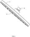
- the water outlet device is the overhead shower, and the water outlet device has a disk shape as a whole and comprises an upper shell 1, a water diverter 2 and a lower panel 3, the upper shell 1 and the lower panel 3 are connected together by covering to define an inner space, the water diverter 2 is disposed in the inner space, a water outlet chamber 4 is defined between the water diverter 2 and the lower panel 3,
- the water outlet device further comprises a water inlet joint 5, the water inlet joint 5 is connected to the upper shell 1 and is in communication with the water outlet chamber 4, the water inlet joint 5 is configured to be in communication with an outer water source and be in communication with the water outlet chamber 4,
- the lower panel 3 comprises a plurality of water outlet ports 31, a water outlet direction of one or more water outlet ports 31 extends along a direction away from the upper shell 1, and the plurality of water outlet ports 31 are uniformly and separately arranged on the lower panel 3.
- the water outlet device comprises a water stopping mechanism 6 disposed in the water outlet chamber 4, the water stopping mechanism 6 comprises one or more pad members 61 configured for elastic deformation, specifically, the water stopping mechanism 6 comprises a plurality of pad members 61, the plurality of pad members 61 correspond to the plurality of water outlet ports 31, the number of the one or more pad members 61 is the same as the number of the one or more water outlet ports 31 in a one-to-one correspondence, alternatively, the number of the one or more pad members 61 is different from the number of the one or more water outlet ports 31, the one or more pad members 61 correspond to some water outlet ports 31 which easily leak water when the water is shut off, alternatively, one pad member 61 corresponds to an outer peripheral of the plurality of water outlet ports 31 so as to hermetically seal the plurality of water outlet ports 31.
- the one or more pad members 61 are integrally formed by elastic materials such as silicone, rubber, and the like, the plurality of pad members 61 are connected together by a same connecting member 62 to form a disk-shaped member, and the disk-shaped member is clamped between the water diverter 2 and the lower panel 3.
- the one or more pad members 61 can be independently fixed between the water diverter 2 and the lower panel 3, alternatively, the one or more pad members 61 can be divided into groups, and each group of the one or more pad members 61 can be connected together by a connecting member 62 to define an integrated member.
- the one or more pad members 61 are movably disposed in the water outlet chamber 4 of the water outlet device, and the one or more pad members 61 at least defines a position-providing space 63; the one or more pad members 61 comprise a water stopping position and an open position.
- the one or more pad members 61 elastically abut an outer peripheral of the one or more water outlet ports 31 of the water outlet chamber 4 to achieve water stopping and hermetical sealing.
- the one or more pad members 61 move toward the position-providing space 63 due to increasing of water pressure in the water outlet chamber 4 to terminate the water stopping and the hermetical sealing so as to move from the water stopping position to the open position, and the one or more pad members 61 elastically deform to accumulate an elastic force.
- the one or more pad members 61 When in the water stopping position, the water outlet chamber 4 is not supplied with water, the one or more pad members 61 elastically abut the outer peripheral of the one or more water outlet ports 31 to achieve the water stopping and the hermetical sealing, when the water outlet chamber 4 is supplied with the water, at this time, the one or more pad members 61 are driven by the water pressure to move toward the position-providing space 63 to move from the water stopping position to the open position due to terminating the water stopping and the hermetical sealing, at this time, the one or more pad members 61 elastically deform to accumulate the elastic force, when supplying of the water to the water outlet chamber 4 is stopped, the elastic force accumulated in the one or more pad members 61 springs back to enable the one or more pad members 61 to hermetically seal and abut the outer peripheral of the one or more water outlet ports 31 again.
- the one or more pad members 61 are configured for automatic feedback according to a change of the water pressure so as to close the one or more water outlet ports 31 to
- the water stopping mechanism 6 further comprises a ventilation hole 611, and the ventilation hole 611 is in communication with the position-providing space 63 and outside air, when the one or more pad members 61 move toward the position-providing space 63, the ventilation hole 611 is configured to maintain an air pressure balance between the position-providing space 63 and the outside air to avoid the one or more pad members 61 having moving difficulty due to an excessive air pressure generated in the position-providing space 63. More specifically, because the one or more water outlet ports 31 are in communication with the outside air, in this embodiment, the ventilation hole 611 is located on the one or more pad members 61 to be in communication with the one or more water outlet ports 31. Referring to FIGS. 7 and 8 , in simple replacement embodiments, the ventilation hole 611 is located on the water diverter 2, and the ventilation hole is directly in communication with the outside air.
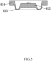
- the one or more pad members 61 comprises a pad body 612 and a deformation member 613 which are integrated to each other, and the deformation member 613 is configured for elastic deformation; the pad body 612 is configured to hermetically seal and abut the outer peripheral of the one or more water outlet ports 31, and the deformation member 613 is configured to apply the elastic force to the pad body 612 toward the one or more water outlet ports 31.
- the pad body 612 is circle-disk-shaped, a periphery of the pad body 612 is enclosed by the deformation member 613, a section of a side of the deformation member 613 adjacent to the pad body 612 is U-shaped, the pad body 612 is configured to move through the deformation member 613, the deformation member 613 is configured to apply a corresponding elastic force to the pad body 612, when the pad body 612 is in the water stopping position, a hermetical sealing connection between the pad body 612 and the one or more water outlet ports 31 is more stable, when the pad body 612 is in the open position, the elastic force is accumulated to enable the pad body 612 to be configured to be reset to the water stopping position once the water pressure is stopped, and a water stopping process is fast and convenient.
- a side of the pad body 612, the water outlet chamber 4 and the deformation member 613 define the position-providing space 63, and another side of the pad body 612 is configured to hermetically seal and abut the outer peripheral of the one or more water outlet ports 31.
- the outer peripheral of the one or more water outlet ports 31 comprises an annular surrounding wall 32, the pad body 612 hermetically seals and abuts an upper side of the annular surrounding wall 32, and the pad body 612 hermetically seals and abuts an upper edge of the annular surrounding wall 32 to achieve the water stopping and the hermetical sealing.
- the pad member 61 further comprises a connecting block 614, the deformation member 613 is connected to and disposed between the pad body 612 and the connecting block 614, and the connecting block 614 is configured to be fixedly connected to the water outlet device.
- the deformation member 613 drives the pad body 612 to elastically hermetically seal and abut the upper edge of the annular surrounding wall 32 to achieve the water stopping of the one or more water outlet ports 31.
- the pad body 612 moves toward the position-providing space 63 due to increasing of the water pressure, at this time, a connection of the hermetical sealing and the water stopping between the pad body 612 and the annular surrounding wall is terminated, the water flow can flow into the one or more water outlet ports 31 from the upper edge of the annular surrounding wall 32, meanwhile, the deformation member 613 accumulates the elastic force, and during this process, the ventilation hole 611 has a function of balancing the air pressure between the position-providing space 63 and the outside air.
- the elastic force accumulated in the deformation member 613 is released to drive the pad body 612 to hermetically seal and abut the upper edge of the annular surrounding wall 32 again to achieve the
- the present invention may be summarized as follows:
- the present disclosure discloses a water stopping mechanism configured for a water outlet device, the water stopping mechanism comprises one or more pad members configured for elastic deformation, the one or more pad members are configured to be movably disposed in a water outlet chamber of the water outlet device, and the one or more pad members at least define a position-providing space; and the one or more pad members comprise a water stopping position and an open position: when in the water stopping position, the one or more pad members elastically hermetically seal and abut an outer peripheral of one or more water outlet ports of the water outlet chamber to achieve water stopping and hermetical sealing; the one or more pad members are configured to move toward the position-providing space due to increasing of water pressure in the water outlet chamber to terminate the water stopping and the hermetical sealing so as to move from the water stopping position to the open position, and the one or more pad members elastically deform to accumulate an elastic force.
- the one or more pad members are configured for automatic feedback according to a change of the water pressure so as to
Landscapes
- Health & Medical Sciences (AREA)
- Life Sciences & Earth Sciences (AREA)
- Engineering & Computer Science (AREA)
- Hydrology & Water Resources (AREA)
- Public Health (AREA)
- Water Supply & Treatment (AREA)
- Nozzles (AREA)
- Domestic Plumbing Installations (AREA)
Applications Claiming Priority (1)
| Application Number | Priority Date | Filing Date | Title |
|---|---|---|---|
| CN202211130350.0A CN117732623A (zh) | 2022-09-15 | 2022-09-15 | 适用于出水装置的止水机构和出水装置 |
Publications (1)
| Publication Number | Publication Date |
|---|---|
| EP4339381A1 true EP4339381A1 (de) | 2024-03-20 |
Family
ID=84389197
Family Applications (1)
| Application Number | Title | Priority Date | Filing Date |
|---|---|---|---|
| EP22211494.4A Pending EP4339381A1 (de) | 2022-09-15 | 2022-12-05 | Wasserstoppmechanismus für wasserauslassvorrichtung und wasserauslassvorrichtung |
Country Status (3)
| Country | Link |
|---|---|
| US (1) | US20240091795A1 (de) |
| EP (1) | EP4339381A1 (de) |
| CN (1) | CN117732623A (de) |
Citations (6)
| Publication number | Priority date | Publication date | Assignee | Title |
|---|---|---|---|---|
| CN103240199A (zh) * | 2013-04-11 | 2013-08-14 | 王思源 | 无滴水稳压花洒 |
| WO2016203270A1 (en) * | 2015-06-19 | 2016-12-22 | Kohler Mira Limited | Spray head |
| EP3276231A1 (de) * | 2016-07-22 | 2018-01-31 | Hansgrohe SE | Brausestrahlerzeugungsvorrichtung |
| DE102018121773A1 (de) * | 2018-09-06 | 2020-03-12 | Grohe Ag | Brausekopf für eine Sanitärarmatur mit einer Mehrzahl von Membranventilen |
| EP3623054A1 (de) * | 2018-09-13 | 2020-03-18 | Toto Ltd. | Duschkopf |
| WO2021037421A1 (de) * | 2019-08-26 | 2021-03-04 | Grohe Ag | Brausekopf für eine sanitärarmatur mit einer mehrzahl von membranventilen |
-
2022
- 2022-09-15 CN CN202211130350.0A patent/CN117732623A/zh active Pending
- 2022-11-29 US US18/070,542 patent/US20240091795A1/en active Pending
- 2022-12-05 EP EP22211494.4A patent/EP4339381A1/de active Pending
Patent Citations (6)
| Publication number | Priority date | Publication date | Assignee | Title |
|---|---|---|---|---|
| CN103240199A (zh) * | 2013-04-11 | 2013-08-14 | 王思源 | 无滴水稳压花洒 |
| WO2016203270A1 (en) * | 2015-06-19 | 2016-12-22 | Kohler Mira Limited | Spray head |
| EP3276231A1 (de) * | 2016-07-22 | 2018-01-31 | Hansgrohe SE | Brausestrahlerzeugungsvorrichtung |
| DE102018121773A1 (de) * | 2018-09-06 | 2020-03-12 | Grohe Ag | Brausekopf für eine Sanitärarmatur mit einer Mehrzahl von Membranventilen |
| EP3623054A1 (de) * | 2018-09-13 | 2020-03-18 | Toto Ltd. | Duschkopf |
| WO2021037421A1 (de) * | 2019-08-26 | 2021-03-04 | Grohe Ag | Brausekopf für eine sanitärarmatur mit einer mehrzahl von membranventilen |
Also Published As
| Publication number | Publication date |
|---|---|
| US20240091795A1 (en) | 2024-03-21 |
| CN117732623A (zh) | 2024-03-22 |
Similar Documents
| Publication | Publication Date | Title |
|---|---|---|
| WO2017156831A1 (zh) | 燃气比例阀 | |
| JP2010531945A (ja) | 膜ポンプ | |
| JP2002530610A (ja) | 弁 | |
| EP4339381A1 (de) | Wasserstoppmechanismus für wasserauslassvorrichtung und wasserauslassvorrichtung | |
| KR20100112928A (ko) | 팬 모터 케이스 실링부재 및 팬 모터 케이스 | |
| JP7104855B2 (ja) | シートエアバッグの圧力制御装置 | |
| CN109340380B (zh) | 电磁阀 | |
| CN108397583B (zh) | 安全阀及使用该安全阀的壁挂炉供暖系统 | |
| CN215568113U (zh) | 阀组件及膜片泵 | |
| KR101462340B1 (ko) | 소음 저감장치 및 이를 구비한 유축기용 압력 조절장치 | |
| CN110906028A (zh) | 一种三通阀结构 | |
| CN112228589A (zh) | 一种阀门结构及电磁阀装置 | |
| CN220185938U (zh) | 燃气负压阀 | |
| EP4501460A1 (de) | Flüssigkeitsauslassvorrichtung und flüssigkeitsauslasssystem | |
| CN211875164U (zh) | 一种三通阀结构 | |
| CN217874337U (zh) | 燃气比例阀以及具有燃气比例阀的灶具 | |
| CN214367917U (zh) | 一种阀门结构及电磁阀装置 | |
| CN218690563U (zh) | 一种适用于出水装置的止水机构和出水装置 | |
| CN218845127U (zh) | 气门组件及比例阀 | |
| CN209910134U (zh) | 新风机的壳体组件及具有其的新风机 | |
| CN212080243U (zh) | 阀芯单元和燃气阀 | |
| CN115999010A (zh) | 可调泄压阀及其装配方法 | |
| CN107750307B (zh) | 隔膜泵总成 | |
| CN223524576U (zh) | 气阀组件及空气波压力治疗仪 | |
| CN223182964U (zh) | 加热不燃烧装置 |
Legal Events
| Date | Code | Title | Description |
|---|---|---|---|
| STAA | Information on the status of an ep patent application or granted ep patent |
Free format text: STATUS: EXAMINATION IS IN PROGRESS |
|
| PUAI | Public reference made under article 153(3) epc to a published international application that has entered the european phase |
Free format text: ORIGINAL CODE: 0009012 |
|
| 17P | Request for examination filed |
Effective date: 20221207 |
|
| AK | Designated contracting states |
Kind code of ref document: A1 Designated state(s): AL AT BE BG CH CY CZ DE DK EE ES FI FR GB GR HR HU IE IS IT LI LT LU LV MC ME MK MT NL NO PL PT RO RS SE SI SK SM TR |
|
| RBV | Designated contracting states (corrected) |
Designated state(s): AL AT BE BG CH CY CZ DE DK EE ES FI FR GB GR HR HU IE IS IT LI LT LU LV MC ME MK MT NL NO PL PT RO RS SE SI SK SM TR |