EP4339381A1 - Water stopping mechanism configured for water outlet device and water outlet device - Google Patents
Water stopping mechanism configured for water outlet device and water outlet device Download PDFInfo
- Publication number
- EP4339381A1 EP4339381A1 EP22211494.4A EP22211494A EP4339381A1 EP 4339381 A1 EP4339381 A1 EP 4339381A1 EP 22211494 A EP22211494 A EP 22211494A EP 4339381 A1 EP4339381 A1 EP 4339381A1
- Authority
- EP
- European Patent Office
- Prior art keywords
- water outlet
- water
- pad members
- outlet device
- pad
- Prior art date
- Legal status (The legal status is an assumption and is not a legal conclusion. Google has not performed a legal analysis and makes no representation as to the accuracy of the status listed.)
- Pending
Links
- XLYOFNOQVPJJNP-UHFFFAOYSA-N water Substances O XLYOFNOQVPJJNP-UHFFFAOYSA-N 0.000 title claims abstract description 229
- 230000007246 mechanism Effects 0.000 title claims abstract description 24
- 230000002093 peripheral effect Effects 0.000 claims abstract description 19
- 238000007789 sealing Methods 0.000 claims abstract description 18
- 230000005489 elastic deformation Effects 0.000 claims abstract description 8
- 238000009423 ventilation Methods 0.000 claims description 18
- 238000004891 communication Methods 0.000 claims description 12
- 230000008859 change Effects 0.000 abstract description 4
- 238000000034 method Methods 0.000 description 3
- 230000008569 process Effects 0.000 description 2
- 238000009825 accumulation Methods 0.000 description 1
- 230000007812 deficiency Effects 0.000 description 1
- 239000013013 elastic material Substances 0.000 description 1
- 238000012986 modification Methods 0.000 description 1
- 230000004048 modification Effects 0.000 description 1
- 229920001296 polysiloxane Polymers 0.000 description 1
Images


Classifications
-
- B—PERFORMING OPERATIONS; TRANSPORTING
- B05—SPRAYING OR ATOMISING IN GENERAL; APPLYING FLUENT MATERIALS TO SURFACES, IN GENERAL
- B05B—SPRAYING APPARATUS; ATOMISING APPARATUS; NOZZLES
- B05B1/00—Nozzles, spray heads or other outlets, with or without auxiliary devices such as valves, heating means
- B05B1/14—Nozzles, spray heads or other outlets, with or without auxiliary devices such as valves, heating means with multiple outlet openings; with strainers in or outside the outlet opening
- B05B1/16—Nozzles, spray heads or other outlets, with or without auxiliary devices such as valves, heating means with multiple outlet openings; with strainers in or outside the outlet opening having selectively- effective outlets
-
- E—FIXED CONSTRUCTIONS
- E03—WATER SUPPLY; SEWERAGE
- E03C—DOMESTIC PLUMBING INSTALLATIONS FOR FRESH WATER OR WASTE WATER; SINKS
- E03C1/00—Domestic plumbing installations for fresh water or waste water; Sinks
- E03C1/02—Plumbing installations for fresh water
- E03C1/04—Water-basin installations specially adapted to wash-basins or baths
- E03C1/0408—Water installations especially for showers
-
- B—PERFORMING OPERATIONS; TRANSPORTING
- B05—SPRAYING OR ATOMISING IN GENERAL; APPLYING FLUENT MATERIALS TO SURFACES, IN GENERAL
- B05B—SPRAYING APPARATUS; ATOMISING APPARATUS; NOZZLES
- B05B1/00—Nozzles, spray heads or other outlets, with or without auxiliary devices such as valves, heating means
- B05B1/14—Nozzles, spray heads or other outlets, with or without auxiliary devices such as valves, heating means with multiple outlet openings; with strainers in or outside the outlet opening
- B05B1/18—Roses; Shower heads
- B05B1/185—Roses; Shower heads characterised by their outlet element; Mounting arrangements therefor
-
- B—PERFORMING OPERATIONS; TRANSPORTING
- B05—SPRAYING OR ATOMISING IN GENERAL; APPLYING FLUENT MATERIALS TO SURFACES, IN GENERAL
- B05B—SPRAYING APPARATUS; ATOMISING APPARATUS; NOZZLES
- B05B1/00—Nozzles, spray heads or other outlets, with or without auxiliary devices such as valves, heating means
- B05B1/30—Nozzles, spray heads or other outlets, with or without auxiliary devices such as valves, heating means designed to control volume of flow, e.g. with adjustable passages
- B05B1/3006—Nozzles, spray heads or other outlets, with or without auxiliary devices such as valves, heating means designed to control volume of flow, e.g. with adjustable passages the controlling element being actuated by the pressure of the fluid to be sprayed
-
- E—FIXED CONSTRUCTIONS
- E03—WATER SUPPLY; SEWERAGE
- E03C—DOMESTIC PLUMBING INSTALLATIONS FOR FRESH WATER OR WASTE WATER; SINKS
- E03C1/00—Domestic plumbing installations for fresh water or waste water; Sinks
- E03C1/12—Plumbing installations for waste water; Basins or fountains connected thereto; Sinks
- E03C1/122—Pipe-line systems for waste water in building
- E03C1/1222—Arrangements of devices in domestic waste water pipe-line systems
- E03C1/1225—Arrangements of devices in domestic waste water pipe-line systems of air admittance valves
Definitions
- the present disclosure relates to a water stopping mechanism configured for a water outlet device and the water outlet device.
- the present disclosure provides a water stopping mechanism configured for a water outlet device and the water outlet device to solve the deficiencies in the background.
- a water stopping mechanism configured for a water outlet device comprises one or more pad members configured for elastic deformation, the one or more pad members are configured to be movably disposed in a water outlet chamber of the water outlet device, and the one or more pad members at least define a position-providing space; and the one or more pad members comprise a water stopping position and an open position.
- the one or more pad members When in the water stopping position, the one or more pad members elastically hermetically seal and abut an outer peripheral of one or more water outlet ports of the water outlet chamber to achieve water stopping and hermetical sealing; the one or more pad members are configured to move toward the position-providing space due to increasing of water pressure in the water outlet chamber to terminate the water stopping and the hermetical sealing so as to move from the water stopping position to the open position, and the one or more pad members elastically deform to accumulate an elastic force.
- it further comprises a ventilation hole, the ventilation hole is in communication with the position-providing space and outside air; and when the one or more pad members move toward the position-providing space, the ventilation hole is configured to maintain an air pressure balance.
- the ventilation hole is in communication with the one or more water outlet ports.
- the one or more pad members comprise a pad body and a deformation member which are integrated to each other, and the deformation member is configured for elastic deformation; and the pad body is configured to hermetically seal and abut the outer peripheral of the one or more water outlet ports, and the deformation member is configured to apply the elastic force to the pad body toward the one or more water outlet ports.
- a periphery of the pad body is enclosed by the deformation member, a side of the pad body, the water outlet chamber and the deformation member define the position-providing space, and another side of the pad body hermetically seals and abuts the outer peripheral of the one or more water outlet ports.
- the outer peripheral of the one or more water outlet ports comprises an annular surrounding wall, and the pad body hermetically seals and abuts an upper side of the annular surrounding wall.
- it comprises a plurality of pad members, and the plurality of pad members respectively correspond to a plurality of water outlet ports.
- it further comprises a connecting member connected to and disposed between the plurality of pad members, and the connecting member is configured to be connected to the water outlet device.
- the one or more pad members comprise a connecting block
- the deformation member is connected to and disposed between the pad body and the connecting block
- the connecting block is configured to be fixedly connected to the water outlet device.
- the present disclosure further provides a water outlet device comprising the water stopping mechanism configured for the water outlet device.
- a water outlet device is provided, the water outlet device is a handheld shower or an overhead shower.
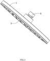
- the water outlet device is the overhead shower, and the water outlet device has a disk shape as a whole and comprises an upper shell 1, a water diverter 2 and a lower panel 3, the upper shell 1 and the lower panel 3 are connected together by covering to define an inner space, the water diverter 2 is disposed in the inner space, a water outlet chamber 4 is defined between the water diverter 2 and the lower panel 3,
- the water outlet device further comprises a water inlet joint 5, the water inlet joint 5 is connected to the upper shell 1 and is in communication with the water outlet chamber 4, the water inlet joint 5 is configured to be in communication with an outer water source and be in communication with the water outlet chamber 4,
- the lower panel 3 comprises a plurality of water outlet ports 31, a water outlet direction of one or more water outlet ports 31 extends along a direction away from the upper shell 1, and the plurality of water outlet ports 31 are uniformly and separately arranged on the lower panel 3.
- the water outlet device comprises a water stopping mechanism 6 disposed in the water outlet chamber 4, the water stopping mechanism 6 comprises one or more pad members 61 configured for elastic deformation, specifically, the water stopping mechanism 6 comprises a plurality of pad members 61, the plurality of pad members 61 correspond to the plurality of water outlet ports 31, the number of the one or more pad members 61 is the same as the number of the one or more water outlet ports 31 in a one-to-one correspondence, alternatively, the number of the one or more pad members 61 is different from the number of the one or more water outlet ports 31, the one or more pad members 61 correspond to some water outlet ports 31 which easily leak water when the water is shut off, alternatively, one pad member 61 corresponds to an outer peripheral of the plurality of water outlet ports 31 so as to hermetically seal the plurality of water outlet ports 31.
- the one or more pad members 61 are integrally formed by elastic materials such as silicone, rubber, and the like, the plurality of pad members 61 are connected together by a same connecting member 62 to form a disk-shaped member, and the disk-shaped member is clamped between the water diverter 2 and the lower panel 3.
- the one or more pad members 61 can be independently fixed between the water diverter 2 and the lower panel 3, alternatively, the one or more pad members 61 can be divided into groups, and each group of the one or more pad members 61 can be connected together by a connecting member 62 to define an integrated member.
- the one or more pad members 61 are movably disposed in the water outlet chamber 4 of the water outlet device, and the one or more pad members 61 at least defines a position-providing space 63; the one or more pad members 61 comprise a water stopping position and an open position.
- the one or more pad members 61 elastically abut an outer peripheral of the one or more water outlet ports 31 of the water outlet chamber 4 to achieve water stopping and hermetical sealing.
- the one or more pad members 61 move toward the position-providing space 63 due to increasing of water pressure in the water outlet chamber 4 to terminate the water stopping and the hermetical sealing so as to move from the water stopping position to the open position, and the one or more pad members 61 elastically deform to accumulate an elastic force.
- the one or more pad members 61 When in the water stopping position, the water outlet chamber 4 is not supplied with water, the one or more pad members 61 elastically abut the outer peripheral of the one or more water outlet ports 31 to achieve the water stopping and the hermetical sealing, when the water outlet chamber 4 is supplied with the water, at this time, the one or more pad members 61 are driven by the water pressure to move toward the position-providing space 63 to move from the water stopping position to the open position due to terminating the water stopping and the hermetical sealing, at this time, the one or more pad members 61 elastically deform to accumulate the elastic force, when supplying of the water to the water outlet chamber 4 is stopped, the elastic force accumulated in the one or more pad members 61 springs back to enable the one or more pad members 61 to hermetically seal and abut the outer peripheral of the one or more water outlet ports 31 again.
- the one or more pad members 61 are configured for automatic feedback according to a change of the water pressure so as to close the one or more water outlet ports 31 to
- the water stopping mechanism 6 further comprises a ventilation hole 611, and the ventilation hole 611 is in communication with the position-providing space 63 and outside air, when the one or more pad members 61 move toward the position-providing space 63, the ventilation hole 611 is configured to maintain an air pressure balance between the position-providing space 63 and the outside air to avoid the one or more pad members 61 having moving difficulty due to an excessive air pressure generated in the position-providing space 63. More specifically, because the one or more water outlet ports 31 are in communication with the outside air, in this embodiment, the ventilation hole 611 is located on the one or more pad members 61 to be in communication with the one or more water outlet ports 31. Referring to FIGS. 7 and 8 , in simple replacement embodiments, the ventilation hole 611 is located on the water diverter 2, and the ventilation hole is directly in communication with the outside air.
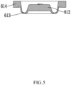
- the one or more pad members 61 comprises a pad body 612 and a deformation member 613 which are integrated to each other, and the deformation member 613 is configured for elastic deformation; the pad body 612 is configured to hermetically seal and abut the outer peripheral of the one or more water outlet ports 31, and the deformation member 613 is configured to apply the elastic force to the pad body 612 toward the one or more water outlet ports 31.
- the pad body 612 is circle-disk-shaped, a periphery of the pad body 612 is enclosed by the deformation member 613, a section of a side of the deformation member 613 adjacent to the pad body 612 is U-shaped, the pad body 612 is configured to move through the deformation member 613, the deformation member 613 is configured to apply a corresponding elastic force to the pad body 612, when the pad body 612 is in the water stopping position, a hermetical sealing connection between the pad body 612 and the one or more water outlet ports 31 is more stable, when the pad body 612 is in the open position, the elastic force is accumulated to enable the pad body 612 to be configured to be reset to the water stopping position once the water pressure is stopped, and a water stopping process is fast and convenient.
- a side of the pad body 612, the water outlet chamber 4 and the deformation member 613 define the position-providing space 63, and another side of the pad body 612 is configured to hermetically seal and abut the outer peripheral of the one or more water outlet ports 31.
- the outer peripheral of the one or more water outlet ports 31 comprises an annular surrounding wall 32, the pad body 612 hermetically seals and abuts an upper side of the annular surrounding wall 32, and the pad body 612 hermetically seals and abuts an upper edge of the annular surrounding wall 32 to achieve the water stopping and the hermetical sealing.
- the pad member 61 further comprises a connecting block 614, the deformation member 613 is connected to and disposed between the pad body 612 and the connecting block 614, and the connecting block 614 is configured to be fixedly connected to the water outlet device.
- the deformation member 613 drives the pad body 612 to elastically hermetically seal and abut the upper edge of the annular surrounding wall 32 to achieve the water stopping of the one or more water outlet ports 31.
- the pad body 612 moves toward the position-providing space 63 due to increasing of the water pressure, at this time, a connection of the hermetical sealing and the water stopping between the pad body 612 and the annular surrounding wall is terminated, the water flow can flow into the one or more water outlet ports 31 from the upper edge of the annular surrounding wall 32, meanwhile, the deformation member 613 accumulates the elastic force, and during this process, the ventilation hole 611 has a function of balancing the air pressure between the position-providing space 63 and the outside air.
- the elastic force accumulated in the deformation member 613 is released to drive the pad body 612 to hermetically seal and abut the upper edge of the annular surrounding wall 32 again to achieve the
- the present invention may be summarized as follows:
- the present disclosure discloses a water stopping mechanism configured for a water outlet device, the water stopping mechanism comprises one or more pad members configured for elastic deformation, the one or more pad members are configured to be movably disposed in a water outlet chamber of the water outlet device, and the one or more pad members at least define a position-providing space; and the one or more pad members comprise a water stopping position and an open position: when in the water stopping position, the one or more pad members elastically hermetically seal and abut an outer peripheral of one or more water outlet ports of the water outlet chamber to achieve water stopping and hermetical sealing; the one or more pad members are configured to move toward the position-providing space due to increasing of water pressure in the water outlet chamber to terminate the water stopping and the hermetical sealing so as to move from the water stopping position to the open position, and the one or more pad members elastically deform to accumulate an elastic force.
- the one or more pad members are configured for automatic feedback according to a change of the water pressure so as to
Abstract
The present disclosure discloses a water stopping mechanism configured for a water outlet device, the water stopping mechanism comprises one or more pad members configured for elastic deformation, the one or more pad members are configured to be movably disposed in a water outlet chamber of the water outlet device, and the one or more pad members at least define a position-providing space; and the one or more pad members comprise a water stopping position and an open position: when in the water stopping position, the one or more pad members elastically hermetically seal and abut an outer peripheral of one or more water outlet ports of the water outlet chamber to achieve water stopping and hermetical sealing; the one or more pad members are configured to move toward the position-providing space due to increasing of water pressure in the water outlet chamber to terminate the water stopping and the hermetical sealing so as to move from the water stopping position to the open position, and the one or more pad members elastically deform to accumulate an elastic force. The one or more pad members are configured for automatic feedback according to a change of the water pressure so as to close the one or more water outlet ports to prevent the water from leaking when the supply of the water is stopped.
Description
- The present disclosure relates to a water stopping mechanism configured for a water outlet device and the water outlet device.
- Take a shower rod as an example of a water outlet device in a family home now; an upper part of the shower rod is equipped with an overhead shower, after water is shut off by a water mixing valve, dripping water will continue for a long time due to water accumulation in a cavity of the conventional overhead shower, at night or in other quieter situations, a noise generated by water droplets will affect the quality of life, and if someone passes through the shower room, it is easy to slip and cause damage.
- The present disclosure provides a water stopping mechanism configured for a water outlet device and the water outlet device to solve the deficiencies in the background.
- In order to solve the technical problem, a first technical solution of the present disclosure is as follows.
- A water stopping mechanism configured for a water outlet device comprises one or more pad members configured for elastic deformation, the one or more pad members are configured to be movably disposed in a water outlet chamber of the water outlet device, and the one or more pad members at least define a position-providing space; and the one or more pad members comprise a water stopping position and an open position.
- When in the water stopping position, the one or more pad members elastically hermetically seal and abut an outer peripheral of one or more water outlet ports of the water outlet chamber to achieve water stopping and hermetical sealing; the one or more pad members are configured to move toward the position-providing space due to increasing of water pressure in the water outlet chamber to terminate the water stopping and the hermetical sealing so as to move from the water stopping position to the open position, and the one or more pad members elastically deform to accumulate an elastic force.
- In a preferred embodiment, it further comprises a ventilation hole, the ventilation hole is in communication with the position-providing space and outside air; and when the one or more pad members move toward the position-providing space, the ventilation hole is configured to maintain an air pressure balance.
- In a preferred embodiment, the ventilation hole is in communication with the one or more water outlet ports.
- In a preferred embodiment, the one or more pad members comprise a pad body and a deformation member which are integrated to each other, and the deformation member is configured for elastic deformation; and the pad body is configured to hermetically seal and abut the outer peripheral of the one or more water outlet ports, and the deformation member is configured to apply the elastic force to the pad body toward the one or more water outlet ports.
- In a preferred embodiment, a periphery of the pad body is enclosed by the deformation member, a side of the pad body, the water outlet chamber and the deformation member define the position-providing space, and another side of the pad body hermetically seals and abuts the outer peripheral of the one or more water outlet ports.
- In a preferred embodiment, the outer peripheral of the one or more water outlet ports comprises an annular surrounding wall, and the pad body hermetically seals and abuts an upper side of the annular surrounding wall.
- In a preferred embodiment, it comprises a plurality of pad members, and the plurality of pad members respectively correspond to a plurality of water outlet ports.
- In a preferred embodiment, it further comprises a connecting member connected to and disposed between the plurality of pad members, and the connecting member is configured to be connected to the water outlet device.
- In a preferred embodiment, the one or more pad members comprise a connecting block, the deformation member is connected to and disposed between the pad body and the connecting block, and the connecting block is configured to be fixedly connected to the water outlet device.
- The present disclosure further provides a water outlet device comprising the water stopping mechanism configured for the water outlet device.
- Compared with the existing techniques, the technical solution has the following advantages.
- 1. When in the water stopping position, the water outlet chamber is not supplied with water, and the one or more pad members elastically hermetically seal and abut the outer peripheral of the one or more water outlet ports to achieve the water stopping and the hermetical sealing. When the water outlet chamber is supplied with the water, the one or more pad members are driven by the water pressure to move toward the position-providing space. At this time, the water stopping and the hermetical sealing is terminated to enable the one or more pad members to move from the water stopping position to the open position. At this time, the one or more pad members elastically deform to accumulate the elastic force. When the supply of water to the water outlet chamber is stopped, the one or more pad members hermetically seal and abut the outer peripheral of one or more water outlet ports again due to spring-back of the elastic force accumulated in the one or more pad members. The one or more pad members are configured for automatic feedback according to a change of the water pressure so as to close the one or more water outlet ports to prevent the water from leaking when the supply of the water is stopped.
- 2. The water stopping mechanism further comprises one or more ventilation holes, and the one or more ventilation holes are in communication with the position-providing space and outside air, when the one or more pad members move toward the position-providing space, the one or more ventilation holes are configured to maintain an air pressure balance between the position-providing space and the outside air to avoid the one or more pad members having moving difficulty due to an excessive air pressure generated in the position-providing space.
-
-
FIG. 1 illustrates a perspective view of a water outlet device in a preferred embodiment in the present disclosure. -
FIG. 2 illustrates a sectional view of the water outlet device in the preferred embodiment in the present disclosure. -
FIG. 3 illustrates an enlarged view of a portion ofFIG. 2 . -
FIG. 4 illustrates a perspective view of a single pad member in the preferred embodiment in the present disclosure. -
FIG. 5 illustrates a sectional view of the single pad member in the preferred embodiment in the present disclosure. -
FIG. 6 illustrates a perspective view of a plurality of pad members connected together to define an integrated member by a connecting member in the preferred embodiment in the present disclosure. -
FIG. 7 illustrates a sectional view of a water outlet device in some simple replacement embodiments in the present disclosure. -
FIG. 8 illustrates a perspective view of a single pad member in some simple replacement embodiments in the present disclosure. - The present disclosure will be further described below in combination with the accompanying drawings and embodiments.
- Referring to
FIGS. 1 to 6 , a water outlet device is provided, the water outlet device is a handheld shower or an overhead shower. In the present disclosure, the water outlet device is the overhead shower, and the water outlet device has a disk shape as a whole and comprises anupper shell 1, awater diverter 2 and alower panel 3, theupper shell 1 and thelower panel 3 are connected together by covering to define an inner space, thewater diverter 2 is disposed in the inner space, a water outlet chamber 4 is defined between thewater diverter 2 and thelower panel 3, the water outlet device further comprises a water inlet joint 5, the water inlet joint 5 is connected to theupper shell 1 and is in communication with the water outlet chamber 4, the water inlet joint 5 is configured to be in communication with an outer water source and be in communication with the water outlet chamber 4, thelower panel 3 comprises a plurality ofwater outlet ports 31, a water outlet direction of one or morewater outlet ports 31 extends along a direction away from theupper shell 1, and the plurality ofwater outlet ports 31 are uniformly and separately arranged on thelower panel 3. - The water outlet device comprises a
water stopping mechanism 6 disposed in the water outlet chamber 4, thewater stopping mechanism 6 comprises one ormore pad members 61 configured for elastic deformation, specifically, thewater stopping mechanism 6 comprises a plurality ofpad members 61, the plurality ofpad members 61 correspond to the plurality ofwater outlet ports 31, the number of the one ormore pad members 61 is the same as the number of the one or morewater outlet ports 31 in a one-to-one correspondence, alternatively, the number of the one ormore pad members 61 is different from the number of the one or morewater outlet ports 31, the one ormore pad members 61 correspond to somewater outlet ports 31 which easily leak water when the water is shut off, alternatively, onepad member 61 corresponds to an outer peripheral of the plurality ofwater outlet ports 31 so as to hermetically seal the plurality ofwater outlet ports 31. - The one or
more pad members 61 are integrally formed by elastic materials such as silicone, rubber, and the like, the plurality ofpad members 61 are connected together by a same connectingmember 62 to form a disk-shaped member, and the disk-shaped member is clamped between thewater diverter 2 and thelower panel 3. Alternatively, the one ormore pad members 61 can be independently fixed between thewater diverter 2 and thelower panel 3, alternatively, the one ormore pad members 61 can be divided into groups, and each group of the one ormore pad members 61 can be connected together by a connectingmember 62 to define an integrated member. - The one or
more pad members 61 are movably disposed in the water outlet chamber 4 of the water outlet device, and the one ormore pad members 61 at least defines a position-providingspace 63; the one ormore pad members 61 comprise a water stopping position and an open position. When in the water stopping position, the one ormore pad members 61 elastically abut an outer peripheral of the one or morewater outlet ports 31 of the water outlet chamber 4 to achieve water stopping and hermetical sealing. The one ormore pad members 61 move toward the position-providingspace 63 due to increasing of water pressure in the water outlet chamber 4 to terminate the water stopping and the hermetical sealing so as to move from the water stopping position to the open position, and the one ormore pad members 61 elastically deform to accumulate an elastic force. - When in the water stopping position, the water outlet chamber 4 is not supplied with water, the one or
more pad members 61 elastically abut the outer peripheral of the one or morewater outlet ports 31 to achieve the water stopping and the hermetical sealing, when the water outlet chamber 4 is supplied with the water, at this time, the one ormore pad members 61 are driven by the water pressure to move toward the position-providingspace 63 to move from the water stopping position to the open position due to terminating the water stopping and the hermetical sealing, at this time, the one ormore pad members 61 elastically deform to accumulate the elastic force, when supplying of the water to the water outlet chamber 4 is stopped, the elastic force accumulated in the one ormore pad members 61 springs back to enable the one ormore pad members 61 to hermetically seal and abut the outer peripheral of the one or morewater outlet ports 31 again. The one ormore pad members 61 are configured for automatic feedback according to a change of the water pressure so as to close the one or morewater outlet ports 31 to prevent the water from leaking from the one or morewater outlet ports 31 when supplying of the water is stopped. - The
water stopping mechanism 6 further comprises aventilation hole 611, and theventilation hole 611 is in communication with the position-providingspace 63 and outside air, when the one ormore pad members 61 move toward the position-providingspace 63, theventilation hole 611 is configured to maintain an air pressure balance between the position-providingspace 63 and the outside air to avoid the one ormore pad members 61 having moving difficulty due to an excessive air pressure generated in the position-providingspace 63. More specifically, because the one or morewater outlet ports 31 are in communication with the outside air, in this embodiment, theventilation hole 611 is located on the one ormore pad members 61 to be in communication with the one or morewater outlet ports 31. Referring toFIGS. 7 and8 , in simple replacement embodiments, theventilation hole 611 is located on thewater diverter 2, and the ventilation hole is directly in communication with the outside air. - The one or
more pad members 61 comprises apad body 612 and adeformation member 613 which are integrated to each other, and thedeformation member 613 is configured for elastic deformation; thepad body 612 is configured to hermetically seal and abut the outer peripheral of the one or morewater outlet ports 31, and thedeformation member 613 is configured to apply the elastic force to thepad body 612 toward the one or morewater outlet ports 31. Thepad body 612 is circle-disk-shaped, a periphery of thepad body 612 is enclosed by thedeformation member 613, a section of a side of thedeformation member 613 adjacent to thepad body 612 is U-shaped, thepad body 612 is configured to move through thedeformation member 613, thedeformation member 613 is configured to apply a corresponding elastic force to thepad body 612, when thepad body 612 is in the water stopping position, a hermetical sealing connection between thepad body 612 and the one or morewater outlet ports 31 is more stable, when thepad body 612 is in the open position, the elastic force is accumulated to enable thepad body 612 to be configured to be reset to the water stopping position once the water pressure is stopped, and a water stopping process is fast and convenient. More specifically, a side of thepad body 612, the water outlet chamber 4 and thedeformation member 613 define the position-providingspace 63, and another side of thepad body 612 is configured to hermetically seal and abut the outer peripheral of the one or morewater outlet ports 31. The outer peripheral of the one or morewater outlet ports 31 comprises an annular surroundingwall 32, thepad body 612 hermetically seals and abuts an upper side of the annular surroundingwall 32, and thepad body 612 hermetically seals and abuts an upper edge of the annular surroundingwall 32 to achieve the water stopping and the hermetical sealing. - For an example in which a
single pad member 61 is connected to the water outlet device, thepad member 61 further comprises a connectingblock 614, thedeformation member 613 is connected to and disposed between thepad body 612 and the connectingblock 614, and the connectingblock 614 is configured to be fixedly connected to the water outlet device. - While in use, when the water is not supplied, the
deformation member 613 drives thepad body 612 to elastically hermetically seal and abut the upper edge of the annular surroundingwall 32 to achieve the water stopping of the one or morewater outlet ports 31. When the water is supplied to the water outlet chamber 4, thepad body 612 moves toward the position-providingspace 63 due to increasing of the water pressure, at this time, a connection of the hermetical sealing and the water stopping between thepad body 612 and the annular surrounding wall is terminated, the water flow can flow into the one or morewater outlet ports 31 from the upper edge of the annular surroundingwall 32, meanwhile, thedeformation member 613 accumulates the elastic force, and during this process, theventilation hole 611 has a function of balancing the air pressure between the position-providingspace 63 and the outside air. When the water supply is stopped, the elastic force accumulated in thedeformation member 613 is released to drive thepad body 612 to hermetically seal and abut the upper edge of the annular surroundingwall 32 again to achieve the hermetical sealing and the water stopping again. - The present invention may be summarized as follows: The present disclosure discloses a water stopping mechanism configured for a water outlet device, the water stopping mechanism comprises one or more pad members configured for elastic deformation, the one or more pad members are configured to be movably disposed in a water outlet chamber of the water outlet device, and the one or more pad members at least define a position-providing space; and the one or more pad members comprise a water stopping position and an open position: when in the water stopping position, the one or more pad members elastically hermetically seal and abut an outer peripheral of one or more water outlet ports of the water outlet chamber to achieve water stopping and hermetical sealing; the one or more pad members are configured to move toward the position-providing space due to increasing of water pressure in the water outlet chamber to terminate the water stopping and the hermetical sealing so as to move from the water stopping position to the open position, and the one or more pad members elastically deform to accumulate an elastic force. The one or more pad members are configured for automatic feedback according to a change of the water pressure so as to close the one or more water outlet ports to prevent the water from leaking when the supply of the water is stopped.
- The aforementioned embodiments are merely some embodiments of the present disclosure, and the scope of the disclosure is not limited thereto. Thus, it is intended that the present disclosure cover any modifications and variations of the presently presented embodiments provided they are made without departing from the appended claims and the specification of the present disclosure.
Claims (10)
- A water stopping mechanism (6) configured for a water outlet device, characterized in that, it comprises one or more pad members (61) configured for elastic deformation, the one or more pad members (61) are configured to be movably disposed in a water outlet chamber (4) of the water outlet device, and the one or more pad members (61) at least define a position-providing space (63); and the one or more pad members (61) comprise a water stopping position and an open position;
when in the water stopping position, the one or more pad members (61) elastically hermetically seal and abut an outer peripheral of one or more water outlet ports (31) of the water outlet chamber (4) to achieve water stopping and hermetical sealing; the one or more pad members (61) are configured to move toward the position-providing space (63) due to increasing of water pressure in the water outlet chamber (4) to terminate the water stopping and the hermetical sealing so as to move from the water stopping position to the open position, and the one or more pad members (61) elastically deform to accumulate an elastic force. - The water stopping mechanism configured for the water outlet device according to claim 1, characterized in that: it further comprises a ventilation hole (611), the ventilation hole (611) is in communication with the position-providing space (63) and outside air; and when the one or more pad members (61) move toward the position-providing space (63), the ventilation hole (611) is configured to maintain an air pressure balance.
- The water stopping mechanism configured for the water outlet device according to claim 2, characterized in that: the ventilation hole (611) is in communication with the one or more water outlet ports (31).
- The water stopping mechanism configured for the water outlet device according to any one or more of claims 1 to 3, characterized in that: the one or more pad members (61) comprise a pad body (612) and a deformation member (613) which are integrated to each other, and the deformation member (613) is configured for elastic deformation; and the pad body (612) is configured to hermetically seal and abut the outer peripheral of the one or more water outlet ports (31), and the deformation member (613) is configured to apply the elastic force to the pad body toward the one or more water outlet ports (31).
- The water stopping mechanism configured for the water outlet device according to claim 4, characterized in that: a periphery of the pad body (612) is enclosed by the deformation member (613), a side of the pad body (612), the water outlet chamber (4) and the deformation member (613) define the position-providing space (63), and another side of the pad body (612) hermetically seals and abuts the outer peripheral of the one or more water outlet ports (31).
- The water stopping mechanism configured for the water outlet device according to claim 4 and/or 5, characterized in that: the outer peripheral of the one or more water outlet ports (31) comprises an annular surrounding wall (32), and the pad body (612) hermetically seals and abuts an upper side of the annular surrounding wall (32).
- The water stopping mechanism configured for the water outlet device according to any one or more of claims 1-6, characterized in that: it comprises a plurality of pad members (61), and the plurality of pad members (61) respectively correspond to a plurality of water outlet ports (31).
- The water stopping mechanism configured for the water outlet device according to claim 7, characterized in that: it further comprises a connecting member (62) connected to and disposed between the plurality of pad members (61), and the connecting member (62) is configured to be connected to the water outlet device.
- The water stopping mechanism configured for the water outlet device according to any one or more of claims 4-8, characterized in that: the one or more pad members (61) comprise a connecting block (614), the deformation member (613) is connected to and disposed between the pad body (612) and the connecting block (614), and the connecting block (614) is configured to be fixedly connected to the water outlet device.
- A water outlet device, characterized in that, it comprises the water stopping mechanism (6) configured for the water outlet device according to any one or more of claims 1-9.
Applications Claiming Priority (1)
| Application Number | Priority Date | Filing Date | Title |
|---|---|---|---|
| CN202211130350.0A CN117732623A (en) | 2022-09-15 | 2022-09-15 | Water stopping mechanism suitable for water outlet device and water outlet device |
Publications (1)
| Publication Number | Publication Date |
|---|---|
| EP4339381A1 true EP4339381A1 (en) | 2024-03-20 |
Family
ID=84389197
Family Applications (1)
| Application Number | Title | Priority Date | Filing Date |
|---|---|---|---|
| EP22211494.4A Pending EP4339381A1 (en) | 2022-09-15 | 2022-12-05 | Water stopping mechanism configured for water outlet device and water outlet device |
Country Status (3)
| Country | Link |
|---|---|
| US (1) | US20240091795A1 (en) |
| EP (1) | EP4339381A1 (en) |
| CN (1) | CN117732623A (en) |
Citations (6)
| Publication number | Priority date | Publication date | Assignee | Title |
|---|---|---|---|---|
| CN103240199A (en) * | 2013-04-11 | 2013-08-14 | 王思源 | Dripless pressure-stabilized sprinkler |
| WO2016203270A1 (en) * | 2015-06-19 | 2016-12-22 | Kohler Mira Limited | Spray head |
| EP3276231A1 (en) * | 2016-07-22 | 2018-01-31 | Hansgrohe SE | Spray jet generating device |
| DE102018121773A1 (en) * | 2018-09-06 | 2020-03-12 | Grohe Ag | Shower head for a sanitary fitting with a plurality of diaphragm valves |
| EP3623054A1 (en) * | 2018-09-13 | 2020-03-18 | Toto Ltd. | Shower head |
| WO2021037421A1 (en) * | 2019-08-26 | 2021-03-04 | Grohe Ag | Shower head for a sanitary fitting, comprising a plurality of diaphragm valves |
-
2022
- 2022-09-15 CN CN202211130350.0A patent/CN117732623A/en active Pending
- 2022-11-29 US US18/070,542 patent/US20240091795A1/en active Pending
- 2022-12-05 EP EP22211494.4A patent/EP4339381A1/en active Pending
Patent Citations (6)
| Publication number | Priority date | Publication date | Assignee | Title |
|---|---|---|---|---|
| CN103240199A (en) * | 2013-04-11 | 2013-08-14 | 王思源 | Dripless pressure-stabilized sprinkler |
| WO2016203270A1 (en) * | 2015-06-19 | 2016-12-22 | Kohler Mira Limited | Spray head |
| EP3276231A1 (en) * | 2016-07-22 | 2018-01-31 | Hansgrohe SE | Spray jet generating device |
| DE102018121773A1 (en) * | 2018-09-06 | 2020-03-12 | Grohe Ag | Shower head for a sanitary fitting with a plurality of diaphragm valves |
| EP3623054A1 (en) * | 2018-09-13 | 2020-03-18 | Toto Ltd. | Shower head |
| WO2021037421A1 (en) * | 2019-08-26 | 2021-03-04 | Grohe Ag | Shower head for a sanitary fitting, comprising a plurality of diaphragm valves |
Also Published As
| Publication number | Publication date |
|---|---|
| US20240091795A1 (en) | 2024-03-21 |
| CN117732623A (en) | 2024-03-22 |
Similar Documents
| Publication | Publication Date | Title |
|---|---|---|
| KR101925401B1 (en) | Automatic ventilation backflow prevention device | |
| US9429159B2 (en) | Pump | |
| WO2017156831A1 (en) | Gas proportional valve | |
| JP2010531945A (en) | Membrane pump | |
| JP2002530610A (en) | valve | |
| EP3669729A1 (en) | Packing and mounting mechanism for electric motor in small and medium-sized appliances | |
| EP4339381A1 (en) | Water stopping mechanism configured for water outlet device and water outlet device | |
| JP7104855B2 (en) | Seat airbag pressure controller | |
| CN106091316B (en) | Air outlet assembly and air conditioner with same | |
| CN112228589A (en) | Valve structure and solenoid valve device | |
| KR101462340B1 (en) | Apparatus for reducing noise and Appratus for controlling pressure for breast pump comprising the same | |
| CN111503324B (en) | Fluid flow control device and gas stove | |
| CN110906028A (en) | Three-way valve structure | |
| CN210510424U (en) | Gas self-closing valve | |
| CN211875164U (en) | Three-way valve structure | |
| CN108397583B (en) | Safety valve and wall-mounted furnace heating system using same | |
| CN218845127U (en) | Valve assembly and proportional valve | |
| KR20000011816A (en) | Device for supplying fuel by means of fuel supply unit provided in a housing | |
| KR200486743Y1 (en) | fan case fixation of Motor damper with hook assembly type | |
| CN212055954U (en) | Heat supply pipeline connecting valve | |
| CN214367917U (en) | Valve structure and solenoid valve device | |
| CN209910134U (en) | Shell assembly of fresh air fan and fresh air fan with shell assembly | |
| TWM586312U (en) | Direct drive type air pumping machine | |
| CN219147321U (en) | Cooking machine | |
| CN212830580U (en) | Sterile respirator |
Legal Events
| Date | Code | Title | Description |
|---|---|---|---|
| STAA | Information on the status of an ep patent application or granted ep patent |
Free format text: STATUS: EXAMINATION IS IN PROGRESS |
|
| PUAI | Public reference made under article 153(3) epc to a published international application that has entered the european phase |
Free format text: ORIGINAL CODE: 0009012 |
|
| 17P | Request for examination filed |
Effective date: 20221207 |
|
| AK | Designated contracting states |
Kind code of ref document: A1 Designated state(s): AL AT BE BG CH CY CZ DE DK EE ES FI FR GB GR HR HU IE IS IT LI LT LU LV MC ME MK MT NL NO PL PT RO RS SE SI SK SM TR |
|
| RBV | Designated contracting states (corrected) |
Designated state(s): AL AT BE BG CH CY CZ DE DK EE ES FI FR GB GR HR HU IE IS IT LI LT LU LV MC ME MK MT NL NO PL PT RO RS SE SI SK SM TR |