EP4339064A1 - Device with a mounting of a traction and buffing device of a coupling system for a railway vehicle - Google Patents
Device with a mounting of a traction and buffing device of a coupling system for a railway vehicle Download PDFInfo
- Publication number
- EP4339064A1 EP4339064A1 EP23195989.1A EP23195989A EP4339064A1 EP 4339064 A1 EP4339064 A1 EP 4339064A1 EP 23195989 A EP23195989 A EP 23195989A EP 4339064 A1 EP4339064 A1 EP 4339064A1
- Authority
- EP
- European Patent Office
- Prior art keywords
- housing structure
- connecting head
- connecting member
- head
- pull rod
- Prior art date
- Legal status (The legal status is an assumption and is not a legal conclusion. Google has not performed a legal analysis and makes no representation as to the accuracy of the status listed.)
- Pending
Links
- 230000008878 coupling Effects 0.000 title claims abstract description 13
- 238000010168 coupling process Methods 0.000 title claims abstract description 13
- 238000005859 coupling reaction Methods 0.000 title claims abstract description 13
- 238000005096 rolling process Methods 0.000 claims description 3
- 125000006850 spacer group Chemical group 0.000 description 6
- 230000006835 compression Effects 0.000 description 3
- 238000007906 compression Methods 0.000 description 3
- 238000010008 shearing Methods 0.000 description 3
- 230000003014 reinforcing effect Effects 0.000 description 2
- 229910001208 Crucible steel Inorganic materials 0.000 description 1
- 229910001141 Ductile iron Inorganic materials 0.000 description 1
- 238000009434 installation Methods 0.000 description 1
- 230000011664 signaling Effects 0.000 description 1
- 239000007787 solid Substances 0.000 description 1
- 239000000725 suspension Substances 0.000 description 1
Images

Classifications
-
- B—PERFORMING OPERATIONS; TRANSPORTING
- B61—RAILWAYS
- B61G—COUPLINGS; DRAUGHT AND BUFFING APPLIANCES
- B61G9/00—Draw-gear
- B61G9/04—Draw-gear combined with buffing appliances
- B61G9/06—Draw-gear combined with buffing appliances with rubber springs
-
- B—PERFORMING OPERATIONS; TRANSPORTING
- B61—RAILWAYS
- B61G—COUPLINGS; DRAUGHT AND BUFFING APPLIANCES
- B61G9/00—Draw-gear
- B61G9/20—Details; Accessories
Definitions
- the invention relates to a device with a holder for a pulling and pushing device of a coupling system for a rail vehicle according to the preamble of claim 1.
- a box-shaped spacer element is provided to bridge the distance, which has a pull rod on the front articulated support element connected and can be fastened on the back in a vehicle recess of the rail vehicle.
- This spacer element which can be fixed in the vehicle body of the rail vehicle using fasteners, has a stop surface on both sides next to the support element, onto which corresponding jaws in the vehicle body engage.
- At least one wedge surface is formed on the back of the spacer element, which interacts with adjustable wedges and by means of which the spacer element can be permanently clamped in the vehicle body. It can also be easily dismantled in the event of damage to the facility.
- a connecting arm preferably aligned parallel to the pull rod, is provided with a compression spring for a supporting compressive force on the pull rod. This means that at least a certain centering height position of the pull rod and thus the coupling can be set.
- the connecting arm with the compression spring is articulated on the one hand to a hub that projects laterally on the support element and on the other hand to a sleeve body of the tie rod.
- This device enables a solid and permanent fixation of the holder of the pulling and pushing device in a vehicle body and also enables this central alignment of the pull rod.
- the invention is based on the object of creating a device according to the type mentioned at the beginning, which limits the play of the connecting head with the spring elements that absorb tension or pressure, in addition to ensuring increased safety Ensuring the functionality of the suspension of the pulling and pushing device is achieved.
- a pressing means which is adjustable in the axial direction is mounted in the connecting head, which rests on the back of the spring element supporting the connecting head on the front side and forms an abutting surface on the front, which can be brought into contact with an end face of this connecting member which can be articulated on the connecting head, at least when the latter is pivoted is, in particular a play limitation is achieved between the connecting member, to which a coupling head is preferably attached, the connecting head and the spring elements.
- the abutting surface of the pressing means and this end face of the connecting member are approximately flat and, in the initial state, are preferably spaced apart and aligned approximately parallel to one another.
- this end face can be brought into rolling contact with the abutting surface of the pressing means.
- the pressing means is pressed with its abutting surface by the spring elements with a compressive force against this end face. This allows the play between the connecting head with the connecting member and the spring elements to be set in a selectable manner and thus the stability in the device can be adjusted.
- the invention provides that the pressure means, which can be adjusted in the axial direction in the connecting head, is composed of a pressure plate with the abutting surface, at least one connecting element and a guide disk attached to the front of the spring element.
- This design of the pressing means provides a simple solution and also enables increased stability of the coupling system.
- the invention is also characterized in that the housing structure can be fixed in the vehicle body of the rail vehicle by fastening means, and can be clamped between at least one jaw arranged in the vehicle body, which engages at the front end of the housing structure, and at least one wedge at the rear in the vehicle recess of the vehicle body .
- the at least one wedge is longitudinally adjustable by a fastening unit arranged parallel in the longitudinal direction of the wedge in such a way that the wedge is fixed in the clamping position after the housing structure has been tightened.
- Fig. 1 to Fig. 3 show a device 10 with a holder for a pulling and pushing device of a coupling system, in particular for a rail vehicle. It is very advantageously suitable for freight wagons in which vehicle recesses 14 'are provided in a vehicle body 14, in each of which a distance bridging is required, in which such a device 10 can be fastened.
- the device 10 is provided with a housing structure 15, a support element 16 arranged therein, a pull rod 11 which is displaceably mounted by the latter in the axial direction A and is provided with a connecting head 20 on the front, and on both sides of the support element 16 with several spring elements 13, 13 lined up on the pull rod 11 ' Mistake.
- the support element 16 is arranged approximately in the middle of the housing structure 15. However, depending on the number of spring elements 13, 13 'or the length of the housing structure, it could be placed in the front or rear part of the latter.
- On the front of the pull rod 11 there is a final spring element 13" and a guide disk 53 which abuts the connecting head 20.
- This connecting head 20 which is fork-like on the front, is designed with an articulation consisting of fork walls 27, 28 and a held joint pin 26 running transversely to the axial direction A which, for example, a connecting member 29 shown can be articulated with a coupling head. However, a coupling head could be articulated directly, which is not shown in more detail.
- This connecting member 29 is tubular at the front and has a bushing 29 'at the back, through whose bore 49 this pivot pin 26 protrudes removably.
- prestressed spring elements 13, 13 serve to dampen the tensile and compressive forces that arise during operation of the rail vehicle, in which, for example, nine can be provided at the front and four at the rear. However, depending on the strength requirements, a different number can be selected. Both these spring elements 13 'acting on tensile force and a stop 19 attached to the end of the pull rod 11 with a fastening means 18 as well as the spring elements 13 loaded under pressure are accommodated within the housing structure 15, through which the spring elements 13 are compressed with a defined pressing force on tension or pressure is made possible. In principle, only one spring element could be arranged in front of and behind the support element 16.
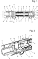
- a pressing means 50 which is adjustable in the axial direction A is mounted in the connecting head 20, as shown in particular Fig. 2 It can be seen that the back rests against the spring element 13" which supports the connecting head 20 at the front and forms an abutment surface 51' at the front, which can be brought into contact with an end face 29" of this connecting member 29 which can be articulated on the connecting head 20, at least when the same is pivoted.
- the connecting member 29 can be swiveled out to approximately 17° to one side or the other in relation to the axial direction A.
- the adjustable pressing means 50 is composed of a pressure plate 51 with the abutment surface 51 ', of at least one connecting element 52 guided in the connecting head 20 and a guide disk 53 which rests on the front side of the first spring element 13".
- the pressure plate 51 is in a chamber 54 by an adjustment stroke S Connecting head 20 is slidably mounted. In the unloaded initial state with the connecting member 29 not pivoted, as shown, the pressure plate 51 is in the extended end position, whereas when the connecting member 29 is pivoted it is guided displaceably up to the rear end position 54 'in the chamber 54.
- connecting elements 52 are fastened on the circumference in the axial direction A in the pressure plate 51, each of which consists, for example, of a bolt, a bearing bush 56 in the connecting head 20 and this guide disk 53.
- the connecting elements 52 are detachably fastened at the front in the guide disk 53.
- This adjustable pressing means 50 could be designed differently than explained above.
- this guide disk 53 could be dispensed with and the connecting elements 52 could be attached directly to holding elements on the frontmost spring element 13" or be in contact.
- the abutment surface 51 'and the end face 29" could already touch each other in the unloaded initial state, so that any play between them would be completely eliminated.
- Such play can therefore be set between zero or at least 13 mm or between 5 mm and 24 mm.
- This housing structure 15 is box-shaped with a square cross section and, together with the support element 16, it is preferably made in one piece from nodular cast iron or cast steel. In principle, it could be designed other than box-shaped and round, oval or similar in cross-section and composed of several parts.
- At the rear end it is provided with an opening 12 'so that the spring elements 13', the fastening means 18 and the stop 19 behind the support element 16 can be inserted into or removed from it.
- At least one, preferably several, recesses 12 are formed on all four side walls in the housing structure 15, which are dimensioned such that the nut 18 of the stop 19 and the spring elements 13 'are accessible for mounting from outside the housing structure 15 or through these recesses 12 also inserted or removed from the side can be. With these recesses 12, weight savings in the housing structure can also be achieved.
- the connecting head 20 and the housing structure 15 are designed with corresponding sliding guides 21, 22, through which the connecting head 20 with the pull rod 11 and the pressure means 50 adjustable therein are guided longitudinally in the housing structure 15 in the axial direction A.
- pairs of dovetail-shaped guideways are designed as sliding guides 21 on both sides of the pull rod 11, which are correspondingly provided in the housing structure 15 starting from the front end 15 'of the same and at legs 23, 24 of the connecting head 20.
- two such sliding guides 21, 22 and correspondingly four such legs 23, 24 are arranged in pairs on both sides of the connecting head 20, so that the latter can be moved back and forth in the axial direction A and is held in a form-fitting manner in the housing structure 15 when viewed transversely to the axial direction A.
- the connecting head 20 and the tie rod 11 connected to it are in the housing structure 15 from a basic position P0 starting in the unloaded operating state, as shown in Fig. 3 is illustrated, up to a stop position P1 present at an operational pressure load.
- the pressing means 50 is additionally pressed against the spring elements 13 in the pressure direction.
- the stroke length H1 of the connecting head 20 from the unloaded basic position P0 to this stop position P1 is dimensioned such that the spring elements 13, 13 'are compressed in the stop position P1 within the elastic range and they or the device are not damaged in whole or in part.
- the stroke length H1 is preferably selected so that the spring elements 13 are compressed in this stop position P1 shortly before the maximum possible compression.
- this stop position P1 could also be dimensioned such that at least some of the spring elements would be plastically deformed or these or possibly parts of the device 10 would be inoperable in the event of an impact.
- the connecting head 20 and with it the tie rod 11 are guided longitudinally in the axial direction A from this basic position P0 in the unloaded state to a fixed end position P2.
- the corresponding stroke length H2 corresponds to the maximum deflection of the spring elements 13" within the elastic range.
- This end position P2 is designed such that the connecting head 20 is still guided with its legs 23, 24 in the housing structure 15.
- the pressing means 50 When the connecting member 29 is pivoted in the opposite direction, it is pressed against the spring elements 13 in the pressure direction, so that its function is guaranteed.
- the housing structure 15 is preferably formed in the front half by the recesses 12 with frame-shaped side walls 17 running in the longitudinal direction, which are provided on the inside with the sliding guides 22 and strips 25 having the stop surfaces 25 '.
- At least one indication element 30 is assigned to the connecting head 20 as a shear bolt with a notch, which is clearly visible below the joint pin 26 and the fork wall 28. If it breaks, if it has been moved to the stop position and broken off there by a shearing element in a support unit 35 for the housing structure 15, this is displayed visually.
- the distance between the shear bolt and the stop position is dimensioned to be approximately the same length as the stroke length H1 of the connecting head 20 up to the stop position P1. In the event of such a break in the shearing element, the entire device must be checked and, if necessary, at least parts of it, along with the shearing element, must be replaced.
- this indication element could be designed instead of a bolt by electrical signaling, for example when the stop surfaces 24, 25 'contact between one of the legs 23, 24 and the bar 25, in which an electrical connection is made through an electrical line, not shown in detail, to a control center , a lamp and/or an acoustic indicator would be generated.
- this could also be done mechanically or electrically using another known indication element.
- the housing structure 15 is supported with several feet 45 on the underside on at least one, preferably on two multi-part support units 35 in the vehicle body 14.
- These support units 35 each include a bracket 36 which extends below the housing structure and screws 37 which can be actuated laterally to the housing structure 15 and which can be screwed into the vehicle body.
- These support units 35 enable the housing structure to be positioned during assembly and thus easier installation of the device 10.
- the housing structure 15 can be fixed in the vehicle body 14 by fasteners.
- jaws arranged in the vehicle body 14 and stops abutting them are provided at the front ends 15 'on both sides of the housing structure 15 and two clampable wedges 39 at the rear in the vehicle recess 14' of the vehicle body 14.
- the two wedges 39 are arranged to be longitudinally adjustable by at least one fastening unit 43 arranged parallel in their longitudinal direction, so that the wedges 39 are fixed in the clamping position after the housing structure 15 has been tightened.
- the fastening unit 43 has at least one adjusting means connected in the housing structure 15 to the wedge 39 by a web 39 ', preferably a screw 42, by means of which the wedge 39 is between the housing structure 15 and the vehicle body 14 can be adjusted and clamped.
- the respective wedge 39 can be fixed by the adjusting means, alias this screw 42 and lock nuts 46.
- the two wedges 39 are each assigned such an adjusting means and they are fastened individually. This achieves a further advantage that these wedges 39 usually remain at the set fixed height in the tenth of a millimeter range when the distance between the housing structure 15 and the vehicle body 14 changes.
- Positioning means 44 are also indicated on the transverse rib 47 for assembly purposes of the device.
- Fig. 4 and Fig. 5 show a variant of the connection head 20 of the device 10, in which the same components have the same reference numbers as in the device Fig. 3 are provided. Only the differences are shown below.
- the connecting head 20 and the housing structure 15 are formed with corresponding sliding guides 61, 62, through which the connecting head 20 with the pull rod 11 and the pressure means 50 adjustable therein is guided longitudinally in the housing structure 15 in the axial direction A.
- the sliding guides 61, 62 are formed by rectangularly angled guide tracks which are provided in the housing structure 15 starting from the front end 15 'of the same and correspondingly at the legs 23, 24 of the connecting head 20. Accordingly, two such sliding guides 61, 62 are formed in pairs on both sides. They have an advantage in their corners rounded, but they could also be angular without these roundings.
- the housing structure 15 in these sliding guides 61, 62 is reinforced by a frame 65 forming the outside, which is formed on the top and bottom by a transverse rib 66, 67 and on the side by the wall ends 63.
- This rectangular closed frame 65 then forms these sliding guides on the inside at its four corners.
- Projecting spacer plates 64 are also attached to the side of these wall ends 63, by means of which the housing structure 15 can be centered in the vehicle body 14. Depending on the play between the two, these spacer plates 64 can be used with a greater or lesser thickness.
- connection head Fig. 4 and Fig. 5 are the same as above for the connection head Fig. 1 to Fig. 3 has been explained.
- this reinforcing frame 65 in the sliding guides 61, 62 a higher rigidity of the guidance of the connecting head is achieved, particularly at the front of the housing structure.
- the corresponding sliding guides of the connecting head and the housing structure could be designed differently, for example as slide rails and rollers guided on them, instead of as dovetail or rectangular guide tracks.
- the connection head In principle, it could also be guided on the outside of the housing structure.
- the sliding guides on the connecting head would then be arranged on the inside and those of the housing structure on the outside.
- the housing structure and with it the connecting head could, for example, be tubular or rectangular in cross section with rounded corners.
- These sliding guides could accordingly also have a round, polygonal or other shape in cross section and be secured against rotation or torsionally rigid.
- This at least one stop 25 in the housing structure and the at least one corresponding stop surface on the respective leg 23, 24 could theoretically be omitted. In a simpler embodiment of the device 10, it could be built without such an indication element and without this reinforcing frame.
Landscapes
- Engineering & Computer Science (AREA)
- Mechanical Engineering (AREA)
- Clamps And Clips (AREA)
Abstract
Eine Einrichtung (10) mit einer Halterung und einer Zug- und Stossvorrichtung eines Kupplungssystems für ein Schienenfahrzeug ist mit einer Gehäusestruktur (15), einem in dieser angeordneten Stützelement (16), einer von letzterem in Achsrichtung (A) verschiebbar gelagerten Zugstange (11), einem mit der Zugstange (11) verbundenen Verbindungskopf (20) und zwischen ihm und dem Stützelement (16) mit vorzugsweise mehreren auf der Zugstange (11) aneinandergereihten Federelementen (13) versehen. Am Verbindungskopf (20) ist ein Verbindungsglied (29) für einen Kupplungskopf anlenkbar, während in ihm ein in Achsrichtung (A) verstellbares Andrückmittel gelagert ist, das rückseitig an dem den Verbindungskopf (20) stirnseitig abstützenden Federelement (13") ansteht und frontseitig eine Stossfläche bildet. Diese Stossfläche ist mit einer endseitigen Stirnfläche dieses am Verbindungskopf (20) anlenkbaren Verbindungsgliedes (29) zumindest bei einem Schwenken desselben in Kontakt bringbar. Damit wird eine Spielbegrenzung zwischen dem Verbindungsglied, dem Verbindungskopf und den Federelementen erzielt.A device (10) with a holder and a pulling and pushing device of a coupling system for a rail vehicle is provided with a housing structure (15), a support element (16) arranged therein, and a pull rod (11) which is displaceably mounted by the latter in the axial direction (A). , a connecting head (20) connected to the pull rod (11) and between it and the support element (16) with preferably several spring elements (13) lined up on the pull rod (11). A connecting member (29) for a coupling head can be articulated on the connecting head (20), while a pressing means which is adjustable in the axial direction (A) is mounted in it, which rests on the back of the spring element (13") which supports the front of the connecting head (20) and on the front Forms abutting surface. This abutting surface can be brought into contact with an end face of this connecting member (29), which can be articulated on the connecting head (20), at least when the same is pivoted. This limits the play between the connecting member, the connecting head and the spring elements.
Description
Die Erfindung betrifft eine Einrichtung mit einer Halterung einer Zug- und Stossvorrichtung eines Kupplungssystems für ein Schienenfahrzeug nach dem Oberbegriff des Anspruchs 1.The invention relates to a device with a holder for a pulling and pushing device of a coupling system for a rail vehicle according to the preamble of claim 1.
Bei einer bekannten gattungsmässigen Einrichtung gemäss der Druckschrift
Zusätzlich ist ein vorzugsweise parallel zur Zugstange ausgerichteter Verbindungsarm mit einer Druckfeder für eine stützende Druckkraft auf die Zugstange vorgesehen. Damit kann zumindest eine bestimmte zentrierende Höhenposition der Zugstange und damit der Kupplung eingestellt werden. Der Verbindungsarm mit der Druckfeder ist dabei einerseits an einer am Stützelement seitlich vorstehenden Nabe und andererseits an einem Hülsenkörper der Zugstange angelenkt.In addition, a connecting arm, preferably aligned parallel to the pull rod, is provided with a compression spring for a supporting compressive force on the pull rod. This means that at least a certain centering height position of the pull rod and thus the coupling can be set. The connecting arm with the compression spring is articulated on the one hand to a hub that projects laterally on the support element and on the other hand to a sleeve body of the tie rod.
Mit dieser Einrichtung wird eine solide und dauerhafte Fixierung der Halterung der Zug- und Stossvorrichtung in einem Fahrzeugkasten und zudem diese zentrische Ausrichtung der Zugstange ermöglicht.This device enables a solid and permanent fixation of the holder of the pulling and pushing device in a vehicle body and also enables this central alignment of the pull rod.
Der Erfindung liegt die Aufgabe zugrunde, eine Einrichtung nach der eingangs erwähnten Gattung zu schaffen, dass mit ihr eine Spielbegrenzung des Verbindungskopfs mit den auf Zug bzw. Druck aufnehmenden Federelementen erzielt wird, nebst dem, dass eine erhöhte Sicherheit der Gewährleistung der Funktionstüchtigkeit der Federung der Zug- und Stossvorrichtung erzielt wird.The invention is based on the object of creating a device according to the type mentioned at the beginning, which limits the play of the connecting head with the spring elements that absorb tension or pressure, in addition to ensuring increased safety Ensuring the functionality of the suspension of the pulling and pushing device is achieved.
Diese Aufgabe ist erfindungsgemäss durch die Merkmale des Anspruchs 1 gelöst.This task is solved according to the invention by the features of claim 1.
Mit dieser erfindungsgemässen Lösung, dass im Verbindungskopf ein in Achsrichtung verstellbares Andrückmittel gelagert ist, das rückseitig an dem den Verbindungskopf stirnseitig abstützenden Federelement ansteht und frontseitig eine Stossfläche bildet, die mit einer endseitigen Stirnfläche dieses am Verbindungskopf anlenkbaren Verbindungsgliedes zumindest bei einem Schwenken desselben in Kontakt bringbar ist, wird insbesondere eine Spielbegrenzung zwischen dem Verbindungsglied, an dem vorzugsweise ein Kupplungskopf befestigt ist, dem Verbindungskopf und den Federelementen erzielt.With this solution according to the invention, a pressing means which is adjustable in the axial direction is mounted in the connecting head, which rests on the back of the spring element supporting the connecting head on the front side and forms an abutting surface on the front, which can be brought into contact with an end face of this connecting member which can be articulated on the connecting head, at least when the latter is pivoted is, in particular a play limitation is achieved between the connecting member, to which a coupling head is preferably attached, the connecting head and the spring elements.
Sehr vorteilhaft sind die Stossfläche des Andrückmittels und diese Stirnfläche des Verbindungsgliedes annähernd eben ausgebildet und im Ausgangszustand vorzugsweise beabstandet und annähernd parallel zueinander ausgerichtet. Hingegen beim Auslenken des Verbindungsgliedes ist diese Stirnfläche mit der Stossfläche des Andrückmittels abwälzend in Kontakt bringbar. Dabei wird das Andrückmittel mit seiner Stossfläche von den Federelementen mit einer Druckkraft gegen diese Stirnfläche gedrückt. Damit kann das Spiel zwischen dem Verbindungskopf mit dem Verbindungsglied und den Federelementen wählbar festgelegt und damit die Stabilität in der Einrichtung angepasst werden.Very advantageously, the abutting surface of the pressing means and this end face of the connecting member are approximately flat and, in the initial state, are preferably spaced apart and aligned approximately parallel to one another. On the other hand, when the connecting member is deflected, this end face can be brought into rolling contact with the abutting surface of the pressing means. The pressing means is pressed with its abutting surface by the spring elements with a compressive force against this end face. This allows the play between the connecting head with the connecting member and the spring elements to be set in a selectable manner and thus the stability in the device can be adjusted.
Die Erfindung sieht vor, dass das im Verbindungskopf in Achsrichtung verstellbare Andrückmittel aus einer Druckplatte mit der Stossfläche, aus wenigstens einem Verbindungselement und einer am Federelement stirnseitig anstehenden Führungsscheibe zusammengesetzt ist. Mit dieser Ausbildung des Andrückmittels ist eine einfache Lösung und überdies die erhöhte Stabilität des Kupplungssystems ermöglicht.The invention provides that the pressure means, which can be adjusted in the axial direction in the connecting head, is composed of a pressure plate with the abutting surface, at least one connecting element and a guide disk attached to the front of the spring element. This design of the pressing means provides a simple solution and also enables increased stability of the coupling system.
Die Erfindung zeichnet sich noch dadurch aus, dass die Gehäusestruktur durch Befestigungsmittel im Fahrzeugkasten des Schienenfahrzeugs fixierbar ist, wobei sie zwischen wenigstens einer im Fahrzeugkasten angeordneten Backe, die beim vorderen Ende der Gehäusestruktur angreift, und mindestens einem Keil hinten in der Fahrzeugausnehmung des Fahrzeugkastens festspannbar ist. Der mindestens eine Keil ist von einer in Längsrichtung des Keils parallel angeordneten Befestigungseinheit derart längsverstellbar, dass der Keil nach dem Festspannen der Gehäusestruktur in der Klemmposition fixiert ist.The invention is also characterized in that the housing structure can be fixed in the vehicle body of the rail vehicle by fastening means, and can be clamped between at least one jaw arranged in the vehicle body, which engages at the front end of the housing structure, and at least one wedge at the rear in the vehicle recess of the vehicle body . The at least one wedge is longitudinally adjustable by a fastening unit arranged parallel in the longitudinal direction of the wedge in such a way that the wedge is fixed in the clamping position after the housing structure has been tightened.
Die Erfindung sowie weitere Vorteile derselben sind anhand von Ausführungsbeispielen unter Bezugnahme auf die Zeichnung nachfolgend näher erläutert. Es zeigt:
- Fig. 1
- einen Längsschnitt einer erfindungsgemässen Einrichtung mit einer Halterung und einer Zug- und Stossvorrichtung einer Kupplung;
- Fig. 2
- einen perspektivischen Teilschnitt der Einrichtung nach
Fig. 1 teils vertikal und teils horizontal; - Fig. 3
- eine perspektivische Seitenansicht der Einrichtung nach
Fig. 1 ; - Fig. 4
- eine perspektivische Seitenansicht der vorderen Bereichs einer Variante einer Einrichtung; und
- Fig. 5
- eine Vorderansicht der Einrichtung nach
Fig. 4 .
- Fig. 1
- a longitudinal section of a device according to the invention with a holder and a pulling and pushing device of a coupling;
- Fig. 2
- a partial perspective section of the facility
Fig. 1 partly vertical and partly horizontal; - Fig. 3
- a perspective side view of the facility
Fig. 1 ; - Fig. 4
- a perspective side view of the front area of a variant of a device; and
- Fig. 5
- a front view of the facility
Fig. 4 .
Die Einrichtung 10 ist mit einer Gehäusestruktur 15, einem in dieser angeordneten Stützelement 16, einer von letzterem in Achsrichtung A verschiebbar gelagerten, vorderseitig mit einem Verbindungskopf 20 versehenen Zugstange 11 und beidseitig des Stützelementes 16 jeweils mit mehreren auf der Zugstange 11 aneinandergereihten Federelementen 13, 13' versehen. Das Stützelement 16 ist annähernd in der Mitte der Gehäusestruktur 15 angeordnet. Es könnte aber je nach Anzahl der Federelemente 13, 13' bzw. der Länge der Gehäusestruktur im vorderen oder hinteren Teil von letzterer platziert sein. Auf der Zugstange 11 ist vorne ein abschliessendes Federelement 13" und eine am Verbindungskopf 20 anstossende Führungsscheibe 53 draufgesetzt. Dieser vorderseitig gabelartig ausgebildete Verbindungskopf 20 ist mit einer Anlenkung bestehend aus Gabelwänden 27, 28 und einem gehaltenen quer zur Achsrichtung A verlaufenden Gelenkzapfen 26 ausgebildet, an den zum Beispiel ein gezeigtes Verbindungsglied 29 mit einem Kupplungskopf anlenkbar ist. Es könnte aber direkt ein Kupplungskopf angelenkt sein, was nicht näher gezeigt ist. Dieses Verbindungsglied 29 ist vorne rohrförmig ausgebildet und weist rückseitig eine Büchse 29' auf, durch deren Bohrung 49 dieser Gelenkzapfen 26 wegnehmbar ragt.The
Diese vorgespannten Federelemente 13, 13' dienen zum Dämpfen der im Betrieb des Schienenfahrzeugs entstehenden Zug- und Druckkräfte, bei denen zum Beispiel vorne neun und hinten vier vorgesehen sein können. Es können aber je nach Anforderung der Kräfte eine andere Anzahl gewählt werden. Sowohl diese auf Zugkraft wirkenden Federelemente 13' und ein am Ende der Zugstange 11 befestigter Anschlag 19 mit einem Befestigungsmittel 18 als auch die auf Druck belasteten Federelemente 13 sind innerhalb der Gehäusestruktur 15 untergebracht, durch die ein Zusammendrücken der Federelemente 13 mit einer definierten Presskraft auf Zug bzw. Druck ermöglicht wird. Im Prinzip könnte auch jeweils vor und hinter dem Stützelement 16 nur ein Federelement angeordnet sein.These
Erfindungsgemäss ist im Verbindungskopf 20 ein in Achsrichtung A verstellbares Andrückmittel 50 gelagert, wie insbesondere aus
Das verstellbare Andrückmittel 50 ist aus einer Druckplatte 51 mit der Stossfläche 51', aus wenigstens einem im Verbindungskopf 20 geführten Verbindungselement 52 und einem am ersten Federelement 13" stirnseitig anstehenden Führungsscheibe 53 zusammengesetzt. Die Druckplatte 51 ist um einen Verstellhub S in einer Kammer 54 im Verbindungskopf 20 verschiebbar gelagert. Im unbelasteten Ausgangszustand bei unverschwenktem Verbindungsglied 29, wie dargestellt, befindet sich die Druckplatte 51 in der ausgeschobenen Endposition, indes bei verschwenktem Verbindungsglied 29 ist sie bis gegen die hintere Endposition 54' in der Kammer 54 verschiebbar geführt. Mit Vorteil sind mehrere Verbindungselemente 52 am Umfang in Achsrichtung A in der Druckplatte 51 befestigt, die jeweils zum Beispiel aus einem Bolzen, einer Lagerbüchse 56 im Verbindungskopf 20 sowie dieser Führungsscheibe 53 bestehen. Die Verbindungselemente 52 sind dabei stirnseitig in der Führungsscheibe 53 lösbar befestigt.The
Dieses verstellbare Andrückmittel 50 könnte anders als oben erläutert ausgestaltet sein. Im Prinzip könnte auf diese Führungsscheibe 53 verzichtet werden und die Verbindungselemente 52 könnten direkt an Halteelementen beim vordersten Federelement 13" befestigt sein oder in Kontakt stehen.This
Bei einem horizontalen Ausschwenken des Verbindungsgliedes 29 drückt die hinterseitige Stirnfläche 29" seiner rückseitigen Büchse 29' an die Stossfläche 51' des Andrückmittels und es erfolgt ein abwälzender Kontakt, so dass das Andrückmittel 50 mit seiner Stossfläche gegen die Federelemente 13 mit einer Druckkraft gedrückt wird. Vorteilhaft sind dabei diese Stossfläche 51' des Andrückmittels 50 und diese Stirnfläche 29" des Verbindungsgliedes 29 annähernd eben ausgebildet und im unbelasteten Ausgangszustand, wie dargestellt, vorzugsweise beabstandet und annähernd parallel zueinander ausgerichtet. Die eine oder die andere oder beide Flächen könnten aber auch statt eben zumindest in ihren seitlichen Randbereichen leicht bombiert oder abgerundet sein, damit nicht eine Kantenberührung zwischen diesen entsteht. Im Prinzip könnten sich die Stossfläche 51' und die Stirnfläche 29" auch bereits im unbelasteten Ausgangszustand berühren, so dass ein Spiel zwischen diesen gänzlich aufgehoben würde. Ein solches Spiel kann somit zwischen Null bzw. mindestens 13 mm oder zwischen 5 mm bis 24 mm festgelegt sein.When the connecting
Gemäss
Bei dieser rückseitigen Öffnung 12' in der Gehäusestruktur 15 können ihre endseitigen Stege 41 zur Verstärkung derselben jeweils oben und/oder unten mit wenigstens je einer diese verbindenden Querrippe 47 versehen sein.In this rear opening 12 'in the
Im Rahmen der Erfindung sind der Verbindungskopf 20 und die Gehäusestruktur 15 mit korrespondierenden Gleitführungen 21, 22 ausgebildet, durch welche der Verbindungskopf 20 mit der Zugstange 11 und dem in diesem verstellbaren Andrückmittel 50 in der Gehäusestruktur 15 in Achsrichtung A längsgeführt sind.Within the scope of the invention, the connecting
Mit dieser neuartigen Ausbildung von Gleitführungen 21, 22 wird diese äusserst stabile Führung des Verbindungskopfs 20 mit dem Andrückmittel 50 und der Zugstange 11 in der Gehäusestruktur 15 erzielt, bei der die Zugstange 11 am vorderen Ende durch den Verbindungskopf 20 und rückseitig durch das Stützelement 16 längsgeführt ist. Es ist ein sphärisch ausgebildetes Drehgelenk 16' im Stützelement 16 angedeutet, welches aber nicht zwingend erforderlich ist, in dem die Zugstange gelagert ist.With this new design of sliding
Ausserdem besteht mit diesen Gleitführungen 21, 22 ein weiterer Vorteil darin, dass ein einfaches Montieren der Einrichtung 10 ermöglicht wird, indem der Verbindungskopf 20 mit dem Andrückmittel 50 und mit der Zugstange 11 in die Gehäusestruktur 15 eingeführt wird, bis dass die Gleitführungen 21, 22 zueinander in Kontakt stehen. Die Zugstange 11 wird dabei durch die Federelemente 13 und das Stützelement 16 hindurchgeführt und mit dem Anschlag 19 und dem Befestigungsmittel 18 befestigt. Beim Demontieren kann in umgekehrter Reihenfolge vorgegangen werden.In addition, with these sliding
Zweckmässigerweise sind beidseitig der Zugstange 11 paarweise schwalbenschwanzförmige Führungsbahnen als Gleitführungen 21 ausgebildet, die korrespondierend in der Gehäusestruktur 15 ausgehend vom vorderen Ende 15' derselben und bei Schenkeln 23, 24 des Verbindungskopfs 20 vorgesehen sind. Vorteilhaft sind paarweise beidseitig je zwei solche Gleitführungen 21, 22 und entsprechend vier solche Schenkel 23, 24 beim Verbindungskopf 20 angeordnet, so dass letzterer in Achsrichtung A hin- und her bewegbar und aber quer zur Achsrichtung A betrachtet formschlüssig in der Gehäusestruktur 15 gehalten ist.Conveniently, pairs of dovetail-shaped guideways are designed as sliding
Der Verbindungskopf 20 und die mit diesem verbundene Zugstange 11 sind in der Gehäusestruktur 15 von einer im unbelasteten Betriebszustand ausgehenden Grundposition P0, wie dies in
Die Hublänge H1 des Verbindungskopfs 20 von der unbelasteten Grundposition P0 bis zu dieser Anschlagsposition P1 ist derart bemessen, dass die Federelemente 13, 13' in der Anschlagsposition P1 innerhalb des elastischen Bereichs zusammengedrückt und sie bzw. die Einrichtung ganz oder teilweise nicht beschädigt sind. Vorzugsweise ist dabei die Hublänge H1 so gewählt, dass die Federelemente 13 in dieser Anschlagsposition P1 kurz vor der maximal möglichen Kompression zusammengedrückt sind. Zu diesem Zweck sind stirnseitig bei den Schenkeln 23, 24 des Verbindungskopfs 20 und in der Gehäusestruktur 15 korrespondierende Anschlagflächen 25' angeordnet, die sich in der Anschlagsposition P1 einander berühren. Im Prinzip könnte diese Anschlagsposition P1 auch so bemessen sein, dass zumindest ein Teil der Federelemente plastisch verformt würden bzw. diese oder gegebenenfalls Teile der Einrichtung 10 bei einem Impact funktionsuntüchtig wären.The stroke length H1 of the connecting
Bei einer Zugbelastung der Zug- und Stossvorrichtung beim Fahren des Schienenfahrzeugs sind der Verbindungskopf 20 und mit ihm die Zugstange 11 in der Achsrichtung A von dieser Grundposition P0 im unbelasteten Zustand bis zu einer festgelegten Endposition P2 längsgeführt. Die entsprechende Hublänge H2 entspricht der maximalen Einfederung der Federelemente 13" innerhalb des elastischen Bereichs. Diese Endposition P2 ist derart ausgelegt, dass der Verbindungskopf 20 mit seinen Schenkeln 23, 24 in der Gehäusestruktur 15 noch geführt ist. Bei einer solchen Zugbelastung wird das Andrückmittel 50 bei einem Verschwenken des Verbindungsgliedes 29 entgegengesetzt gegen die Federelemente 13 in Druckrichtung gedrückt, so dass seine Funktion gewährleistet ist.When the pulling and pushing device is subjected to a tensile load when the rail vehicle is moving, the connecting
Die Gehäusestruktur 15 ist vorzugsweise in der vorderen Hälfte durch die Ausnehmungen 12 mit in Längsrichtung verlaufenden rahmenförmigen Seitenwänden 17 ausgebildet, die innenseitig mit den Gleitführungen 22 und die Anschlagflächen 25' aufweisenden Leisten 25 versehen sind.The
Dem Verbindungskopf 20 ist wenigstens ein Indikationselement 30 als Abscherbolzen mit einer Kerbe zugeordnet, welches unterhalb des Gelenkzapfens 26 und der Gabelwand 28 gut sichtbar befestigt ist. Bei einem Bruch desselben, wenn es bis zur Anschlagsposition bewegt und dort durch ein Scherelement bei einer Trageinheit 35 für die Gehäusestruktur 15 abgebrochen worden ist, wird dies visuell angezeigt. Die Distanz zwischen dem Abscherbolzen und der Anschlagsposition ist annähernd gleich lang wie die Hublänge H1 des Verbindungskopfs 20 bis zur Anschlagsposition P1 dimensioniert. Bei einem solchen Bruch des Scherelementes muss die gesamte Einrichtung geprüft und gegebenenfalls nebst dem Scherelement zumindest Teile von ihr ausgewechselt werden.At least one
Selbstverständlich könnte dieses Indikationselement statt als Bolzen durch eine elektrische Signalgebung zum Beispiel bei einem Kontakt der Anschlagflächen 24, 25' zwischen einem der Schenkel 23, 24 und der Leiste 25 ausgestaltet sein, bei dem eine elektrische Verbindung durch eine nicht näher gezeigte Elektroleitung zu einer Zentrale, zu einer Lampe und/ oder zu einem akustischen Indikator erzeugt würde. Dies könnte aber auch durch ein anderes bekanntes Indikationselement mechanisch oder elektrisch erfolgen.Of course, this indication element could be designed instead of a bolt by electrical signaling, for example when the stop surfaces 24, 25 'contact between one of the
In
Ausserdem ist die Gehäusestruktur 15 mit mehreren unterseitigen Füssen 45 auf wenigstens einer, vorzugsweise auf zwei mehrteiligen Trageinheiten 35 im Fahrzeugkasten 14 abgestützt. Diese Trageinheiten 35 umfassen jeweils ein sich unterhalb der Gehäusestruktur erstreckenden Bügel 36 und seitlich zur Gehäusestruktur 15 betätigbaren Schrauben 37, die im Fahrzeugkasten festschraubbar sind. Diese Trageinheiten 35 ermöglichen beim Montieren ein Positionieren der Gehäusestruktur und damit einen einfacheren Einbau der Einrichtung 10.In addition, the
Die Gehäusestruktur 15 ist durch Befestigungsmittel im Fahrzeugkasten 14 fixierbar. Zu diesem Zwecke sind im Fahrzeugkasten 14 angeordnete Backen und an diese anstossende Anschläge bei den vorderen Enden 15' beidseitig der Gehäusestruktur 15 und rückseitig zwei festspannbare Keile 39 hinten in der Fahrzeugausnehmung 14' des Fahrzeugkastens 14 vorgesehen. Die beiden Keile 39 sind von mindestens einer in ihrer Längsrichtung parallel angeordneten Befestigungseinheit 43 längsverstellbar angeordnet, so dass die Keile 39 nach dem Festspannen der Gehäusestruktur 15 in der Klemmposition fixiert sind.The
Die Befestigungseinheit 43 weist wenigstens ein in der Gehäusestruktur 15 mit dem Keil 39 durch einen Steg 39' verbundenes Verstellmittel auf, vorzugsweise eine Schraube 42, mittels welchem der Keil 39 zwischen der Gehäusestruktur 15 und dem Fahrzeugkasten 14 verstellbar und festklemmbar ist. In der Klemmposition ist der jeweilige Keil 39 durch das Verstellmittel alias diese Schraube 42 und Kontermuttern 46 fixierbar. Vorteilhaft sind den beiden Keilen 39 jeweils ein solches Verstellmittel zugeordnet und sie werden einzeln befestigt. Damit wird als weiterer Vorteil erreicht, dass diese Keile 39 bei einer Veränderung der Distanz zwischen der Gehäusestruktur 15 und dem Fahrzeugkasten 14 üblicherweise im Zehntelmillimeterbereich auf der eingestellten fixen Höhe verbleiben. Es sind ferner noch Positioniermittel 44 bei der Querrippe 47 für Montagezwecke der Einrichtung angedeutet.The
Statt schwalbenschwanzförmige Führungsbahnen, wie bei der Variante nach
Dabei ist die Gehäusestruktur 15 bei diesen Gleitführungen 61, 62 durch einen diese aussen bildenden Rahmen 65 verstärkt, der ober- und unterseitig durch je eine Querrippe 66, 67 und seitlich durch die Wandabschlüsse 63 gebildet ist. Dieser rechteckige geschlossene Rahmen 65 bildet dann innen bei seinen vier Ecken diese Gleitführungen. Seitlich bei diesen Wandabschlüssen 63 sind ausserdem vorstehende Distanzplatten 64 befestigt, mittels denen eine Zentrierung der Gehäusestruktur 15 im Fahrzeugkasten 14 ermöglicht wird. Je nach Spiel zwischen den beiden können diese Distanzplatten 64 mit einer mehr oder weniger grossen Dicke eingesetzt werden.The
Die Funktionsweise dieses Verbindungskopfs nach
Die Erfindung ist mit dem oben erläuterten Ausführungsbeispiel ausreichend dargetan.The invention is sufficiently demonstrated with the exemplary embodiment explained above.
Als Variante könnten die korrespondierenden Gleitführungen des Verbindungskopfs und der Gehäusestruktur statt als schwalbenschwanz- oder rechteckförmige Führungsbahnen andersförmig zum Beispiel als Gleitschienen und auf diesen geführten Rollen ausgebildet sein. Der Verbindungskopf könnte im Prinzip auch aussenseitig der Gehäusestruktur geführt sein. Die Gleitführungen beim Verbindungskopf wären dann innen- und diejenigen der Gehäusestruktur entsprechend aussenseitig angeordnet. Ebenso könnte die Gehäusestruktur und mit ihr der Verbindungskopf beispielsweise rohrförmig oder im Querschnitt rechteckförmig mit abgerundeten Ecken geformt sein. Diese Gleitführungen könnten entsprechend ebenfalls im Querschnitt rund, mehreckig oder andersförmig ausgebildet und dabei drehgesichert bzw. torsionssteif sein.As a variant, the corresponding sliding guides of the connecting head and the housing structure could be designed differently, for example as slide rails and rollers guided on them, instead of as dovetail or rectangular guide tracks. The connection head In principle, it could also be guided on the outside of the housing structure. The sliding guides on the connecting head would then be arranged on the inside and those of the housing structure on the outside. Likewise, the housing structure and with it the connecting head could, for example, be tubular or rectangular in cross section with rounded corners. These sliding guides could accordingly also have a round, polygonal or other shape in cross section and be secured against rotation or torsionally rigid.
Dieser wenigstens eine Anschlag 25 in der Gehäusestruktur und die wenigstens eine korrespondierende Anschlagfläche beim jeweiligen Schenkel 23, 24 könnten theoretisch weggelassen werden. Bei einer einfacheren Ausführung der Einrichtung 10 könnte diese ohne ein solches Indikationselement und ohne diesen Verstärkungsrahmen gebaut sein.This at least one
Claims (13)
im Verbindungskopf (20) ein in Achsrichtung (A) verstellbares Andrückmittel (50) gelagert ist, das rückseitig an dem den Verbindungskopf (20) stirnseitig abstützenden Federelement (13") ansteht und frontseitig eine Stossfläche (51') bildet, die mit einer endseitigen Stirnfläche (29") dieses am Verbindungskopf (20) anlenkbaren Verbindungsgliedes (29) zumindest bei einem Schwenken desselben in Kontakt bringbar ist.Device with a holder and a pulling and pushing device of a coupling system for a rail vehicle, which has a housing structure (15), a support element (16) arranged therein, a pull rod (11) which is displaceably mounted by the latter in the axial direction (A), a with the connecting head (20) connected to the pull rod (11) and between it and the support element (16) is provided with preferably several spring elements (13) lined up on the pull rod (11), with a connecting member (29) for a coupling head on the connecting head (20). is articulated, characterized in that
A pressing means (50) is mounted in the connecting head (20), which can be adjusted in the axial direction (A), which rests on the back of the spring element (13") which supports the connecting head (20) at the front and forms an abutment surface (51') on the front, which is connected to an end End face (29") of this connecting member (29), which can be articulated on the connecting head (20), can be brought into contact at least when it is pivoted.
das im Verbindungskopf (20) in Achsrichtung (A) verstellbare Andrückmittel (50) aus einer Druckplatte (51) mit der Stossfläche (51'), aus wenigstens einem geführten Verbindungselement (52) und einer am Federelement (13") stirnseitig anstehenden Führungsscheibe (53) zusammengesetzt ist.Device according to claim 1 or 2, characterized in that
the pressure means (50), which can be adjusted in the connecting head (20) in the axial direction (A), consists of a pressure plate (51) with the abutment surface (51 '), at least one guided connecting element (52) and a guide disk located on the front side of the spring element (13") ( 53) is composed.
der gabelartig ausgebildete Verbindungskopf (20) zueinander beabstandete Gabelwände (27, 28) und wenigstens einen von diesen gehaltenen quer zur Achsrichtung (A) verlaufenden Gelenkzapfen (26) aufweist, welcher im montierten Zustand durch eine Bohrung (49) einer endseitigen Büchse (29') des Verbindungsgliedes (29) ragt, wobei endseitig bei der Büchse (29') diese Stirnfläche (29") gebildet ist, welche benachbart zu der Stossfläche (51') des verstellbaren Andrückmittels (50) angrenzt.Device according to one of the preceding claims 1 to 4, characterized in that
the fork-like connecting head (20) has fork walls (27, 28) spaced apart from one another and at least one pivot pin (26) held by these and running transversely to the axial direction (A), which in the assembled state passes through a bore (49) in an end bushing (29' ) of the connecting member (29), with this end face (29") being formed at the end of the bushing (29 '), which is adjacent to the abutting surface (51') of the adjustable pressing means (50).
die Gehäusestruktur (15) durch Befestigungsmittel im Fahrzeugkasten (14) des Schienenfahrzeugs fixierbar ist, wobei sie zwischen wenigstens einer im Fahrzeugkasten angeordneten Backe, die beim vorderen Ende (15') der Gehäusestruktur (15) angreift, und mindestens einem Keil (39) hinten in der Fahrzeugausnehmung (14') des Fahrzeugkastens (14) festspannbar ist.Device according to one of the preceding claims 1 to 5, characterized in that
the housing structure (15) can be fixed in the vehicle body (14) of the rail vehicle by fastening means, being between at least one jaw arranged in the vehicle body, which engages the front end (15 ') of the housing structure (15), and at least one wedge (39) at the rear can be clamped in the vehicle recess (14 ') of the vehicle body (14).
der Verbindungskopf (20) und die Gehäusestruktur (15) mit korrespondierenden Gleitführungen (21, 22, 61, 62) ausgebildet sind, durch welche der Verbindungskopf (20) mit der Zugstange (11) und das in diesem verstellbare Andrückmittel (50) in der Gehäusestruktur (15) in Achsrichtung (A) längsgeführt sind.Device according to one of the preceding claims 1 to 8, characterized in that
the connecting head (20) and the housing structure (15) are designed with corresponding sliding guides (21, 22, 61, 62), through which the connecting head (20) is connected to the pull rod (11) and the pressure means (50) adjustable in this Housing structure (15) is guided longitudinally in the axial direction (A).
die Gehäusestruktur (15) durch einen Rahmen (65) verstärkt ist, bei dem innenseitig die Gleitführungen (61, 62) für die Führung des Verbindungskopfs (20) gebildet sind.Device according to one of the preceding claims 9 to 11, characterized in that
the housing structure (15) is reinforced by a frame (65), in which the sliding guides (61, 62) for guiding the connecting head (20) are formed on the inside.
Applications Claiming Priority (2)
| Application Number | Priority Date | Filing Date | Title |
|---|---|---|---|
| CH001067/2022A CH720032B1 (en) | 2022-09-13 | 2022-09-13 | Device for a mounting of a draw and buffer device of a coupling, in particular of a rail vehicle. |
| CH000399/2023A CH720035A2 (en) | 2022-09-13 | 2023-04-18 | Device with a bracket and a pulling and pushing device of a coupling system for a rail vehicle |
Publications (1)
| Publication Number | Publication Date |
|---|---|
| EP4339064A1 true EP4339064A1 (en) | 2024-03-20 |
Family
ID=89898836
Family Applications (1)
| Application Number | Title | Priority Date | Filing Date |
|---|---|---|---|
| EP23195989.1A Pending EP4339064A1 (en) | 2022-09-13 | 2023-09-07 | Device with a mounting of a traction and buffing device of a coupling system for a railway vehicle |
Country Status (1)
| Country | Link |
|---|---|
| EP (1) | EP4339064A1 (en) |
Cited By (1)
| Publication number | Priority date | Publication date | Assignee | Title |
|---|---|---|---|---|
| EP4434843A1 (en) * | 2023-03-20 | 2024-09-25 | KNORR-BREMSE Systeme für Schienenfahrzeuge GmbH | Traction and buffing device, especially for a central buffer coupling |
Citations (4)
| Publication number | Priority date | Publication date | Assignee | Title |
|---|---|---|---|---|
| DE2228539A1 (en) * | 1971-07-02 | 1973-01-11 | Mini Verkehrswesen | PULLING AND PUSHING DEVICE FOR CENTRAL BUFFER COUPLINGS OF RAIL VEHICLES |
| EP1858741B1 (en) * | 2005-03-17 | 2009-04-29 | Faiveley Transport Remscheid GmbH | Pulling and pushing device for a central buffer coupling of rail vehicles |
| EP3792137A1 (en) | 2019-09-12 | 2021-03-17 | Faiveley Transport Schwab AG | Device for fixing a traction and pushing direction of a coupling, especially a rail vehicle |
| WO2022223426A1 (en) * | 2021-04-19 | 2022-10-27 | Voith Patent Gmbh | Draw and buffer gear for a railway coupling, and railway coupling |
-
2023
- 2023-09-07 EP EP23195989.1A patent/EP4339064A1/en active Pending
Patent Citations (4)
| Publication number | Priority date | Publication date | Assignee | Title |
|---|---|---|---|---|
| DE2228539A1 (en) * | 1971-07-02 | 1973-01-11 | Mini Verkehrswesen | PULLING AND PUSHING DEVICE FOR CENTRAL BUFFER COUPLINGS OF RAIL VEHICLES |
| EP1858741B1 (en) * | 2005-03-17 | 2009-04-29 | Faiveley Transport Remscheid GmbH | Pulling and pushing device for a central buffer coupling of rail vehicles |
| EP3792137A1 (en) | 2019-09-12 | 2021-03-17 | Faiveley Transport Schwab AG | Device for fixing a traction and pushing direction of a coupling, especially a rail vehicle |
| WO2022223426A1 (en) * | 2021-04-19 | 2022-10-27 | Voith Patent Gmbh | Draw and buffer gear for a railway coupling, and railway coupling |
Cited By (1)
| Publication number | Priority date | Publication date | Assignee | Title |
|---|---|---|---|---|
| EP4434843A1 (en) * | 2023-03-20 | 2024-09-25 | KNORR-BREMSE Systeme für Schienenfahrzeuge GmbH | Traction and buffing device, especially for a central buffer coupling |
Similar Documents
| Publication | Publication Date | Title |
|---|---|---|
| EP3792137B1 (en) | Device for fixing a traction and pushing direction of a coupling, especially a rail vehicle | |
| EP0060498B1 (en) | Apparatus for connecting two abutting reinforcing bar ends by a sleeve | |
| DE2535315A1 (en) | COMPRESSION DEVICE | |
| DE2644096C2 (en) | Support and guide bends for cast strands, in particular for cast slab strands | |
| EP4339064A1 (en) | Device with a mounting of a traction and buffing device of a coupling system for a railway vehicle | |
| DE1580908B2 (en) | HANGING FOR CIRCULAR CABLE CARS | |
| DE2325148C3 (en) | Device for assembling profiles for metal structures | |
| CH720035A2 (en) | Device with a bracket and a pulling and pushing device of a coupling system for a rail vehicle | |
| DE1257190B (en) | Device for supporting the buffer bar against the frame head carrier of rail vehicles | |
| EP0484783B1 (en) | Device for bracing and balancing the press tool holder and crankcase in an upsetting press | |
| DE2757703C2 (en) | Jaw crusher | |
| DE4022764C2 (en) | Removable trailer attachment | |
| EP4588751A1 (en) | Device with a traction and buffing device of a coupling system for a railway vehicle | |
| AT394009B (en) | TRACK BRAKE ELEMENT | |
| CH716600B1 (en) | Device for holding a pull and push direction of a coupling, in particular of a rail vehicle. | |
| EP3708287B1 (en) | Carrier for a welding machine, in particular for a grid welding machine | |
| EP4434843A1 (en) | Traction and buffing device, especially for a central buffer coupling | |
| DE1816956C3 (en) | Fastening device for a wheel handlebar | |
| DE2749664A1 (en) | Clamping mechanism for coal transporter pipes - has additional coupling accommodating higher loading with great play | |
| DE709694C (en) | Guide stick holder | |
| DE2315369A1 (en) | COUPLING JOINT FOR INDEPENDENT CENTER BUFFER COUPLINGS ON RAIL VEHICLES | |
| DE2655537C2 (en) | Rail brake damper | |
| DE3307778A1 (en) | Quick-connector arrangement | |
| DE9110041U1 (en) | Belt conveyor | |
| DE10237045A1 (en) | Telescopic adjustable-length coupling rod for rail wagons has three or four transverse force transfer points between tubes at each part separation point |
Legal Events
| Date | Code | Title | Description |
|---|---|---|---|
| PUAI | Public reference made under article 153(3) epc to a published international application that has entered the european phase |
Free format text: ORIGINAL CODE: 0009012 |
|
| STAA | Information on the status of an ep patent application or granted ep patent |
Free format text: STATUS: THE APPLICATION HAS BEEN PUBLISHED |
|
| AK | Designated contracting states |
Kind code of ref document: A1 Designated state(s): AL AT BE BG CH CY CZ DE DK EE ES FI FR GB GR HR HU IE IS IT LI LT LU LV MC ME MK MT NL NO PL PT RO RS SE SI SK SM TR |
|
| STAA | Information on the status of an ep patent application or granted ep patent |
Free format text: STATUS: REQUEST FOR EXAMINATION WAS MADE |
|
| 17P | Request for examination filed |
Effective date: 20240828 |
|
| RBV | Designated contracting states (corrected) |
Designated state(s): AL AT BE BG CH CY CZ DE DK EE ES FI FR GB GR HR HU IE IS IT LI LT LU LV MC ME MK MT NL NO PL PT RO RS SE SI SK SM TR |