EP4339064A1 - Dispositif avec un support d'un dispositif de traction et de poussée d'un système d'attelage pour un véhicule ferroviaire - Google Patents
Dispositif avec un support d'un dispositif de traction et de poussée d'un système d'attelage pour un véhicule ferroviaire Download PDFInfo
- Publication number
- EP4339064A1 EP4339064A1 EP23195989.1A EP23195989A EP4339064A1 EP 4339064 A1 EP4339064 A1 EP 4339064A1 EP 23195989 A EP23195989 A EP 23195989A EP 4339064 A1 EP4339064 A1 EP 4339064A1
- Authority
- EP
- European Patent Office
- Prior art keywords
- housing structure
- connecting head
- connecting member
- head
- pull rod
- Prior art date
- Legal status (The legal status is an assumption and is not a legal conclusion. Google has not performed a legal analysis and makes no representation as to the accuracy of the status listed.)
- Pending
Links
Images

Classifications
-
- B—PERFORMING OPERATIONS; TRANSPORTING
- B61—RAILWAYS
- B61G—COUPLINGS; DRAUGHT AND BUFFING APPLIANCES
- B61G9/00—Draw-gear
- B61G9/04—Draw-gear combined with buffing appliances
- B61G9/06—Draw-gear combined with buffing appliances with rubber springs
-
- B—PERFORMING OPERATIONS; TRANSPORTING
- B61—RAILWAYS
- B61G—COUPLINGS; DRAUGHT AND BUFFING APPLIANCES
- B61G9/00—Draw-gear
- B61G9/20—Details; Accessories
Definitions
- the invention relates to a device with a holder for a pulling and pushing device of a coupling system for a rail vehicle according to the preamble of claim 1.
- a box-shaped spacer element is provided to bridge the distance, which has a pull rod on the front articulated support element connected and can be fastened on the back in a vehicle recess of the rail vehicle.
- This spacer element which can be fixed in the vehicle body of the rail vehicle using fasteners, has a stop surface on both sides next to the support element, onto which corresponding jaws in the vehicle body engage.
- At least one wedge surface is formed on the back of the spacer element, which interacts with adjustable wedges and by means of which the spacer element can be permanently clamped in the vehicle body. It can also be easily dismantled in the event of damage to the facility.
- a connecting arm preferably aligned parallel to the pull rod, is provided with a compression spring for a supporting compressive force on the pull rod. This means that at least a certain centering height position of the pull rod and thus the coupling can be set.
- the connecting arm with the compression spring is articulated on the one hand to a hub that projects laterally on the support element and on the other hand to a sleeve body of the tie rod.
- This device enables a solid and permanent fixation of the holder of the pulling and pushing device in a vehicle body and also enables this central alignment of the pull rod.
- the invention is based on the object of creating a device according to the type mentioned at the beginning, which limits the play of the connecting head with the spring elements that absorb tension or pressure, in addition to ensuring increased safety Ensuring the functionality of the suspension of the pulling and pushing device is achieved.
- a pressing means which is adjustable in the axial direction is mounted in the connecting head, which rests on the back of the spring element supporting the connecting head on the front side and forms an abutting surface on the front, which can be brought into contact with an end face of this connecting member which can be articulated on the connecting head, at least when the latter is pivoted is, in particular a play limitation is achieved between the connecting member, to which a coupling head is preferably attached, the connecting head and the spring elements.
- the abutting surface of the pressing means and this end face of the connecting member are approximately flat and, in the initial state, are preferably spaced apart and aligned approximately parallel to one another.
- this end face can be brought into rolling contact with the abutting surface of the pressing means.
- the pressing means is pressed with its abutting surface by the spring elements with a compressive force against this end face. This allows the play between the connecting head with the connecting member and the spring elements to be set in a selectable manner and thus the stability in the device can be adjusted.
- the invention provides that the pressure means, which can be adjusted in the axial direction in the connecting head, is composed of a pressure plate with the abutting surface, at least one connecting element and a guide disk attached to the front of the spring element.
- This design of the pressing means provides a simple solution and also enables increased stability of the coupling system.
- the invention is also characterized in that the housing structure can be fixed in the vehicle body of the rail vehicle by fastening means, and can be clamped between at least one jaw arranged in the vehicle body, which engages at the front end of the housing structure, and at least one wedge at the rear in the vehicle recess of the vehicle body .
- the at least one wedge is longitudinally adjustable by a fastening unit arranged parallel in the longitudinal direction of the wedge in such a way that the wedge is fixed in the clamping position after the housing structure has been tightened.
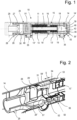
- Fig. 1 to Fig. 3 show a device 10 with a holder for a pulling and pushing device of a coupling system, in particular for a rail vehicle. It is very advantageously suitable for freight wagons in which vehicle recesses 14 'are provided in a vehicle body 14, in each of which a distance bridging is required, in which such a device 10 can be fastened.
- the device 10 is provided with a housing structure 15, a support element 16 arranged therein, a pull rod 11 which is displaceably mounted by the latter in the axial direction A and is provided with a connecting head 20 on the front, and on both sides of the support element 16 with several spring elements 13, 13 lined up on the pull rod 11 ' Mistake.
- the support element 16 is arranged approximately in the middle of the housing structure 15. However, depending on the number of spring elements 13, 13 'or the length of the housing structure, it could be placed in the front or rear part of the latter.
- On the front of the pull rod 11 there is a final spring element 13" and a guide disk 53 which abuts the connecting head 20.
- This connecting head 20 which is fork-like on the front, is designed with an articulation consisting of fork walls 27, 28 and a held joint pin 26 running transversely to the axial direction A which, for example, a connecting member 29 shown can be articulated with a coupling head. However, a coupling head could be articulated directly, which is not shown in more detail.
- This connecting member 29 is tubular at the front and has a bushing 29 'at the back, through whose bore 49 this pivot pin 26 protrudes removably.
- prestressed spring elements 13, 13 serve to dampen the tensile and compressive forces that arise during operation of the rail vehicle, in which, for example, nine can be provided at the front and four at the rear. However, depending on the strength requirements, a different number can be selected. Both these spring elements 13 'acting on tensile force and a stop 19 attached to the end of the pull rod 11 with a fastening means 18 as well as the spring elements 13 loaded under pressure are accommodated within the housing structure 15, through which the spring elements 13 are compressed with a defined pressing force on tension or pressure is made possible. In principle, only one spring element could be arranged in front of and behind the support element 16.
- a pressing means 50 which is adjustable in the axial direction A is mounted in the connecting head 20, as shown in particular Fig. 2 It can be seen that the back rests against the spring element 13" which supports the connecting head 20 at the front and forms an abutment surface 51' at the front, which can be brought into contact with an end face 29" of this connecting member 29 which can be articulated on the connecting head 20, at least when the same is pivoted.
- the connecting member 29 can be swiveled out to approximately 17° to one side or the other in relation to the axial direction A.
- the adjustable pressing means 50 is composed of a pressure plate 51 with the abutment surface 51 ', of at least one connecting element 52 guided in the connecting head 20 and a guide disk 53 which rests on the front side of the first spring element 13".
- the pressure plate 51 is in a chamber 54 by an adjustment stroke S Connecting head 20 is slidably mounted. In the unloaded initial state with the connecting member 29 not pivoted, as shown, the pressure plate 51 is in the extended end position, whereas when the connecting member 29 is pivoted it is guided displaceably up to the rear end position 54 'in the chamber 54.
- connecting elements 52 are fastened on the circumference in the axial direction A in the pressure plate 51, each of which consists, for example, of a bolt, a bearing bush 56 in the connecting head 20 and this guide disk 53.
- the connecting elements 52 are detachably fastened at the front in the guide disk 53.
- This adjustable pressing means 50 could be designed differently than explained above.
- this guide disk 53 could be dispensed with and the connecting elements 52 could be attached directly to holding elements on the frontmost spring element 13" or be in contact.
- the abutment surface 51 'and the end face 29" could already touch each other in the unloaded initial state, so that any play between them would be completely eliminated.
- Such play can therefore be set between zero or at least 13 mm or between 5 mm and 24 mm.
- This housing structure 15 is box-shaped with a square cross section and, together with the support element 16, it is preferably made in one piece from nodular cast iron or cast steel. In principle, it could be designed other than box-shaped and round, oval or similar in cross-section and composed of several parts.
- At the rear end it is provided with an opening 12 'so that the spring elements 13', the fastening means 18 and the stop 19 behind the support element 16 can be inserted into or removed from it.
- At least one, preferably several, recesses 12 are formed on all four side walls in the housing structure 15, which are dimensioned such that the nut 18 of the stop 19 and the spring elements 13 'are accessible for mounting from outside the housing structure 15 or through these recesses 12 also inserted or removed from the side can be. With these recesses 12, weight savings in the housing structure can also be achieved.
- the connecting head 20 and the housing structure 15 are designed with corresponding sliding guides 21, 22, through which the connecting head 20 with the pull rod 11 and the pressure means 50 adjustable therein are guided longitudinally in the housing structure 15 in the axial direction A.
- pairs of dovetail-shaped guideways are designed as sliding guides 21 on both sides of the pull rod 11, which are correspondingly provided in the housing structure 15 starting from the front end 15 'of the same and at legs 23, 24 of the connecting head 20.
- two such sliding guides 21, 22 and correspondingly four such legs 23, 24 are arranged in pairs on both sides of the connecting head 20, so that the latter can be moved back and forth in the axial direction A and is held in a form-fitting manner in the housing structure 15 when viewed transversely to the axial direction A.
- the connecting head 20 and the tie rod 11 connected to it are in the housing structure 15 from a basic position P0 starting in the unloaded operating state, as shown in Fig. 3 is illustrated, up to a stop position P1 present at an operational pressure load.
- the pressing means 50 is additionally pressed against the spring elements 13 in the pressure direction.
- the stroke length H1 of the connecting head 20 from the unloaded basic position P0 to this stop position P1 is dimensioned such that the spring elements 13, 13 'are compressed in the stop position P1 within the elastic range and they or the device are not damaged in whole or in part.
- the stroke length H1 is preferably selected so that the spring elements 13 are compressed in this stop position P1 shortly before the maximum possible compression.
- this stop position P1 could also be dimensioned such that at least some of the spring elements would be plastically deformed or these or possibly parts of the device 10 would be inoperable in the event of an impact.
- the connecting head 20 and with it the tie rod 11 are guided longitudinally in the axial direction A from this basic position P0 in the unloaded state to a fixed end position P2.
- the corresponding stroke length H2 corresponds to the maximum deflection of the spring elements 13" within the elastic range.
- This end position P2 is designed such that the connecting head 20 is still guided with its legs 23, 24 in the housing structure 15.
- the pressing means 50 When the connecting member 29 is pivoted in the opposite direction, it is pressed against the spring elements 13 in the pressure direction, so that its function is guaranteed.
- the housing structure 15 is preferably formed in the front half by the recesses 12 with frame-shaped side walls 17 running in the longitudinal direction, which are provided on the inside with the sliding guides 22 and strips 25 having the stop surfaces 25 '.
- At least one indication element 30 is assigned to the connecting head 20 as a shear bolt with a notch, which is clearly visible below the joint pin 26 and the fork wall 28. If it breaks, if it has been moved to the stop position and broken off there by a shearing element in a support unit 35 for the housing structure 15, this is displayed visually.
- the distance between the shear bolt and the stop position is dimensioned to be approximately the same length as the stroke length H1 of the connecting head 20 up to the stop position P1. In the event of such a break in the shearing element, the entire device must be checked and, if necessary, at least parts of it, along with the shearing element, must be replaced.
- this indication element could be designed instead of a bolt by electrical signaling, for example when the stop surfaces 24, 25 'contact between one of the legs 23, 24 and the bar 25, in which an electrical connection is made through an electrical line, not shown in detail, to a control center , a lamp and/or an acoustic indicator would be generated.
- this could also be done mechanically or electrically using another known indication element.
- the housing structure 15 is supported with several feet 45 on the underside on at least one, preferably on two multi-part support units 35 in the vehicle body 14.
- These support units 35 each include a bracket 36 which extends below the housing structure and screws 37 which can be actuated laterally to the housing structure 15 and which can be screwed into the vehicle body.
- These support units 35 enable the housing structure to be positioned during assembly and thus easier installation of the device 10.
- the housing structure 15 can be fixed in the vehicle body 14 by fasteners.
- jaws arranged in the vehicle body 14 and stops abutting them are provided at the front ends 15 'on both sides of the housing structure 15 and two clampable wedges 39 at the rear in the vehicle recess 14' of the vehicle body 14.
- the two wedges 39 are arranged to be longitudinally adjustable by at least one fastening unit 43 arranged parallel in their longitudinal direction, so that the wedges 39 are fixed in the clamping position after the housing structure 15 has been tightened.
- the fastening unit 43 has at least one adjusting means connected in the housing structure 15 to the wedge 39 by a web 39 ', preferably a screw 42, by means of which the wedge 39 is between the housing structure 15 and the vehicle body 14 can be adjusted and clamped.
- the respective wedge 39 can be fixed by the adjusting means, alias this screw 42 and lock nuts 46.
- the two wedges 39 are each assigned such an adjusting means and they are fastened individually. This achieves a further advantage that these wedges 39 usually remain at the set fixed height in the tenth of a millimeter range when the distance between the housing structure 15 and the vehicle body 14 changes.
- Positioning means 44 are also indicated on the transverse rib 47 for assembly purposes of the device.
- Fig. 4 and Fig. 5 show a variant of the connection head 20 of the device 10, in which the same components have the same reference numbers as in the device Fig. 3 are provided. Only the differences are shown below.
- the connecting head 20 and the housing structure 15 are formed with corresponding sliding guides 61, 62, through which the connecting head 20 with the pull rod 11 and the pressure means 50 adjustable therein is guided longitudinally in the housing structure 15 in the axial direction A.
- the sliding guides 61, 62 are formed by rectangularly angled guide tracks which are provided in the housing structure 15 starting from the front end 15 'of the same and correspondingly at the legs 23, 24 of the connecting head 20. Accordingly, two such sliding guides 61, 62 are formed in pairs on both sides. They have an advantage in their corners rounded, but they could also be angular without these roundings.
- the housing structure 15 in these sliding guides 61, 62 is reinforced by a frame 65 forming the outside, which is formed on the top and bottom by a transverse rib 66, 67 and on the side by the wall ends 63.
- This rectangular closed frame 65 then forms these sliding guides on the inside at its four corners.
- Projecting spacer plates 64 are also attached to the side of these wall ends 63, by means of which the housing structure 15 can be centered in the vehicle body 14. Depending on the play between the two, these spacer plates 64 can be used with a greater or lesser thickness.
- connection head Fig. 4 and Fig. 5 are the same as above for the connection head Fig. 1 to Fig. 3 has been explained.
- this reinforcing frame 65 in the sliding guides 61, 62 a higher rigidity of the guidance of the connecting head is achieved, particularly at the front of the housing structure.
- the corresponding sliding guides of the connecting head and the housing structure could be designed differently, for example as slide rails and rollers guided on them, instead of as dovetail or rectangular guide tracks.
- the connection head In principle, it could also be guided on the outside of the housing structure.
- the sliding guides on the connecting head would then be arranged on the inside and those of the housing structure on the outside.
- the housing structure and with it the connecting head could, for example, be tubular or rectangular in cross section with rounded corners.
- These sliding guides could accordingly also have a round, polygonal or other shape in cross section and be secured against rotation or torsionally rigid.
- This at least one stop 25 in the housing structure and the at least one corresponding stop surface on the respective leg 23, 24 could theoretically be omitted. In a simpler embodiment of the device 10, it could be built without such an indication element and without this reinforcing frame.
Landscapes
- Engineering & Computer Science (AREA)
- Mechanical Engineering (AREA)
- Clamps And Clips (AREA)
Applications Claiming Priority (2)
| Application Number | Priority Date | Filing Date | Title |
|---|---|---|---|
| CH001067/2022A CH720032B1 (de) | 2022-09-13 | 2022-09-13 | Einrichtung für eine Halterung einer Zug- und Stossvorrichtung einer Kupplung insbesondere eines Schienenfahrzeugs. |
| CH000399/2023A CH720035A2 (de) | 2022-09-13 | 2023-04-18 | Einrichtung mit einer Halterung und einer Zug- und Stossvorrichtung eines Kupplungssystems für ein Schienenfahrzeug |
Publications (1)
| Publication Number | Publication Date |
|---|---|
| EP4339064A1 true EP4339064A1 (fr) | 2024-03-20 |
Family
ID=89898836
Family Applications (1)
| Application Number | Title | Priority Date | Filing Date |
|---|---|---|---|
| EP23195989.1A Pending EP4339064A1 (fr) | 2022-09-13 | 2023-09-07 | Dispositif avec un support d'un dispositif de traction et de poussée d'un système d'attelage pour un véhicule ferroviaire |
Country Status (1)
| Country | Link |
|---|---|
| EP (1) | EP4339064A1 (fr) |
Cited By (1)
| Publication number | Priority date | Publication date | Assignee | Title |
|---|---|---|---|---|
| EP4434843A1 (fr) * | 2023-03-20 | 2024-09-25 | KNORR-BREMSE Systeme für Schienenfahrzeuge GmbH | Dispositif de tamponnement et de traction, notamment pour attelage central |
Citations (4)
| Publication number | Priority date | Publication date | Assignee | Title |
|---|---|---|---|---|
| DE2228539A1 (de) * | 1971-07-02 | 1973-01-11 | Mini Verkehrswesen | Zug- und stossvorrichtung fuer mittelpufferkupplungen von schienenfahrzeugen |
| EP1858741B1 (fr) * | 2005-03-17 | 2009-04-29 | Faiveley Transport Remscheid GmbH | Dispositif de traction et de poussee pour des attelages a tampon central de vehicules sur rails |
| EP3792137A1 (fr) | 2019-09-12 | 2021-03-17 | Faiveley Transport Schwab AG | Dispositif pour le maintien d'une direction de traction et de poussée d'un accouplement, en particulier d'un véhicule ferroviaire |
| WO2022223426A1 (fr) * | 2021-04-19 | 2022-10-27 | Voith Patent Gmbh | Dispositif de traction et de tampon pour accouplement de chemin de fer, et accouplement de chemin de fer |
-
2023
- 2023-09-07 EP EP23195989.1A patent/EP4339064A1/fr active Pending
Patent Citations (4)
| Publication number | Priority date | Publication date | Assignee | Title |
|---|---|---|---|---|
| DE2228539A1 (de) * | 1971-07-02 | 1973-01-11 | Mini Verkehrswesen | Zug- und stossvorrichtung fuer mittelpufferkupplungen von schienenfahrzeugen |
| EP1858741B1 (fr) * | 2005-03-17 | 2009-04-29 | Faiveley Transport Remscheid GmbH | Dispositif de traction et de poussee pour des attelages a tampon central de vehicules sur rails |
| EP3792137A1 (fr) | 2019-09-12 | 2021-03-17 | Faiveley Transport Schwab AG | Dispositif pour le maintien d'une direction de traction et de poussée d'un accouplement, en particulier d'un véhicule ferroviaire |
| WO2022223426A1 (fr) * | 2021-04-19 | 2022-10-27 | Voith Patent Gmbh | Dispositif de traction et de tampon pour accouplement de chemin de fer, et accouplement de chemin de fer |
Cited By (1)
| Publication number | Priority date | Publication date | Assignee | Title |
|---|---|---|---|---|
| EP4434843A1 (fr) * | 2023-03-20 | 2024-09-25 | KNORR-BREMSE Systeme für Schienenfahrzeuge GmbH | Dispositif de tamponnement et de traction, notamment pour attelage central |
Similar Documents
| Publication | Publication Date | Title |
|---|---|---|
| EP3792137B1 (fr) | Dispositif pour le maintien d'une direction de traction et de poussée d'un accouplement, en particulier d'un véhicule ferroviaire | |
| EP0060498B1 (fr) | Appareil pour l'assemblage bout à bout de deux tiges de renforcement au moyen d'un manchon d'accouplement | |
| DE2644096C2 (de) | Stütz- und Führungsbogen für Gußstränge, insbesondere für Brammengußstränge | |
| EP2009157A1 (fr) | Dispositif d'accouplement pour un cadre à lisses | |
| EP4339064A1 (fr) | Dispositif avec un support d'un dispositif de traction et de poussée d'un système d'attelage pour un véhicule ferroviaire | |
| EP4588751A1 (fr) | Dispositif avec un dispositif de traction et tamponnement d'un système d'attelage pour un véhicule ferroviaire | |
| DE1580908B2 (de) | Gehaenge fuer umlauf-seilschwebebahnen | |
| CH720035A2 (de) | Einrichtung mit einer Halterung und einer Zug- und Stossvorrichtung eines Kupplungssystems für ein Schienenfahrzeug | |
| EP2887047A1 (fr) | Cadre coulissant, dispositif de contrôle et procédé de détermination d'au moins une propriété d'un échantillon | |
| DE1257190B (de) | Vorrichtung zum Abstuetzen des Pufferbalkens gegenueber dem Rahmenkopftraeger von Schienenfahrzeugen | |
| DE102019132222A1 (de) | Verbindungselement zur Verbindung eines Schalungsunterstützungskopfes mit einer Rohrstütze | |
| EP0484783B1 (fr) | Dispositif pour le haubanage et l'équilibrage du porte-outil de pressage et de la boîte de manivelle d'une presse à refouler | |
| DE2757703C2 (de) | Backenbrecher | |
| DE4022764C2 (de) | Abnehmbare Anhängerkupplung | |
| AT394009B (de) | Gleisbremselement | |
| CH716600B1 (de) | Einrichtung für eine Halterung einer Zug- und Stossrichtung einer Kupplung insbesondere eines Schienenfahrzeugs. | |
| EP3708287B1 (fr) | Chariot de déplacement pour une machine à souder, en particulier pour une machine à souder de grillage | |
| EP4434843A1 (fr) | Dispositif de tamponnement et de traction, notamment pour attelage central | |
| DE20019891U1 (de) | Vorrichtung zum zeitweiligen Verbinden eines bewegbaren Gegenstandes mit einer Halteschiene | |
| DE20105680U1 (de) | Befestigungseinrichtung für Absperrungen an Gleisen | |
| DE1816956C3 (de) | Befestigungsvorrichtung für einen Radlenker | |
| DE2749664A1 (de) | Verbindungs- und sicherungsvorrichtung fuer die foerderanlagen mit oder ohne fuehrungen fuer gewinnungsanlagen insbesondere fuer kohle | |
| DE709694C (de) | Spurlattenhalter | |
| EP4703232A1 (fr) | Dispositif de support pour le centrage ou la déviation, de préférence d'une tête d'accouplement d'un véhicule ferroviaire | |
| DE2315369A1 (de) | Kupplungsgelenk fuer selbsttaetige mittelpufferkupplungen an schienenfahrzeugen |
Legal Events
| Date | Code | Title | Description |
|---|---|---|---|
| PUAI | Public reference made under article 153(3) epc to a published international application that has entered the european phase |
Free format text: ORIGINAL CODE: 0009012 |
|
| STAA | Information on the status of an ep patent application or granted ep patent |
Free format text: STATUS: THE APPLICATION HAS BEEN PUBLISHED |
|
| AK | Designated contracting states |
Kind code of ref document: A1 Designated state(s): AL AT BE BG CH CY CZ DE DK EE ES FI FR GB GR HR HU IE IS IT LI LT LU LV MC ME MK MT NL NO PL PT RO RS SE SI SK SM TR |
|
| STAA | Information on the status of an ep patent application or granted ep patent |
Free format text: STATUS: REQUEST FOR EXAMINATION WAS MADE |
|
| 17P | Request for examination filed |
Effective date: 20240828 |
|
| RBV | Designated contracting states (corrected) |
Designated state(s): AL AT BE BG CH CY CZ DE DK EE ES FI FR GB GR HR HU IE IS IT LI LT LU LV MC ME MK MT NL NO PL PT RO RS SE SI SK SM TR |
|
| GRAP | Despatch of communication of intention to grant a patent |
Free format text: ORIGINAL CODE: EPIDOSNIGR1 |
|
| STAA | Information on the status of an ep patent application or granted ep patent |
Free format text: STATUS: GRANT OF PATENT IS INTENDED |