EP4339050B1 - Steuerung für ein fahrzeug und verfahren - Google Patents
Steuerung für ein fahrzeug und verfahren Download PDFInfo
- Publication number
- EP4339050B1 EP4339050B1 EP23206807.2A EP23206807A EP4339050B1 EP 4339050 B1 EP4339050 B1 EP 4339050B1 EP 23206807 A EP23206807 A EP 23206807A EP 4339050 B1 EP4339050 B1 EP 4339050B1
- Authority
- EP
- European Patent Office
- Prior art keywords
- vehicle
- controller
- speed
- period
- gradient
- Prior art date
- Legal status (The legal status is an assumption and is not a legal conclusion. Google has not performed a legal analysis and makes no representation as to the accuracy of the status listed.)
- Active
Links
Images


Classifications
-
- B—PERFORMING OPERATIONS; TRANSPORTING
- B60—VEHICLES IN GENERAL
- B60T—VEHICLE BRAKE CONTROL SYSTEMS OR PARTS THEREOF; BRAKE CONTROL SYSTEMS OR PARTS THEREOF, IN GENERAL; ARRANGEMENT OF BRAKING ELEMENTS ON VEHICLES IN GENERAL; PORTABLE DEVICES FOR PREVENTING UNWANTED MOVEMENT OF VEHICLES; VEHICLE MODIFICATIONS TO FACILITATE COOLING OF BRAKES
- B60T7/00—Brake-action initiating means
- B60T7/12—Brake-action initiating means for automatic initiation; for initiation not subject to will of driver or passenger
- B60T7/22—Brake-action initiating means for automatic initiation; for initiation not subject to will of driver or passenger initiated by contact of vehicle, e.g. bumper, with an external object, e.g. another vehicle, or by means of contactless obstacle detectors mounted on the vehicle
-
- B—PERFORMING OPERATIONS; TRANSPORTING
- B60—VEHICLES IN GENERAL
- B60T—VEHICLE BRAKE CONTROL SYSTEMS OR PARTS THEREOF; BRAKE CONTROL SYSTEMS OR PARTS THEREOF, IN GENERAL; ARRANGEMENT OF BRAKING ELEMENTS ON VEHICLES IN GENERAL; PORTABLE DEVICES FOR PREVENTING UNWANTED MOVEMENT OF VEHICLES; VEHICLE MODIFICATIONS TO FACILITATE COOLING OF BRAKES
- B60T8/00—Arrangements for adjusting wheel-braking force to meet varying vehicular or ground-surface conditions, e.g. limiting or varying distribution of braking force
- B60T8/24—Arrangements for adjusting wheel-braking force to meet varying vehicular or ground-surface conditions, e.g. limiting or varying distribution of braking force responsive to vehicle inclination or change of direction, e.g. negotiating bends
- B60T8/245—Longitudinal vehicle inclination
-
- B—PERFORMING OPERATIONS; TRANSPORTING
- B60—VEHICLES IN GENERAL
- B60T—VEHICLE BRAKE CONTROL SYSTEMS OR PARTS THEREOF; BRAKE CONTROL SYSTEMS OR PARTS THEREOF, IN GENERAL; ARRANGEMENT OF BRAKING ELEMENTS ON VEHICLES IN GENERAL; PORTABLE DEVICES FOR PREVENTING UNWANTED MOVEMENT OF VEHICLES; VEHICLE MODIFICATIONS TO FACILITATE COOLING OF BRAKES
- B60T8/00—Arrangements for adjusting wheel-braking force to meet varying vehicular or ground-surface conditions, e.g. limiting or varying distribution of braking force
- B60T8/32—Arrangements for adjusting wheel-braking force to meet varying vehicular or ground-surface conditions, e.g. limiting or varying distribution of braking force responsive to a speed condition, e.g. acceleration or deceleration
- B60T8/86—Arrangements for adjusting wheel-braking force to meet varying vehicular or ground-surface conditions, e.g. limiting or varying distribution of braking force responsive to a speed condition, e.g. acceleration or deceleration wherein the brakes are automatically applied in accordance with a speed condition and having means for overriding the automatic braking device when a skid condition occurs
-
- B—PERFORMING OPERATIONS; TRANSPORTING
- B60—VEHICLES IN GENERAL
- B60W—CONJOINT CONTROL OF VEHICLE SUB-UNITS OF DIFFERENT TYPE OR DIFFERENT FUNCTION; CONTROL SYSTEMS SPECIALLY ADAPTED FOR HYBRID VEHICLES; ROAD VEHICLE DRIVE CONTROL SYSTEMS FOR PURPOSES NOT RELATED TO THE CONTROL OF A PARTICULAR SUB-UNIT
- B60W10/00—Conjoint control of vehicle sub-units of different type or different function
- B60W10/18—Conjoint control of vehicle sub-units of different type or different function including control of braking systems
-
- B—PERFORMING OPERATIONS; TRANSPORTING
- B60—VEHICLES IN GENERAL
- B60W—CONJOINT CONTROL OF VEHICLE SUB-UNITS OF DIFFERENT TYPE OR DIFFERENT FUNCTION; CONTROL SYSTEMS SPECIALLY ADAPTED FOR HYBRID VEHICLES; ROAD VEHICLE DRIVE CONTROL SYSTEMS FOR PURPOSES NOT RELATED TO THE CONTROL OF A PARTICULAR SUB-UNIT
- B60W30/00—Purposes of road vehicle drive control systems not related to the control of a particular sub-unit, e.g. of systems using conjoint control of vehicle sub-units
- B60W30/18—Propelling the vehicle
- B60W30/18009—Propelling the vehicle related to particular drive situations
- B60W30/18063—Creeping
-
- B—PERFORMING OPERATIONS; TRANSPORTING
- B60—VEHICLES IN GENERAL
- B60W—CONJOINT CONTROL OF VEHICLE SUB-UNITS OF DIFFERENT TYPE OR DIFFERENT FUNCTION; CONTROL SYSTEMS SPECIALLY ADAPTED FOR HYBRID VEHICLES; ROAD VEHICLE DRIVE CONTROL SYSTEMS FOR PURPOSES NOT RELATED TO THE CONTROL OF A PARTICULAR SUB-UNIT
- B60W30/00—Purposes of road vehicle drive control systems not related to the control of a particular sub-unit, e.g. of systems using conjoint control of vehicle sub-units
- B60W30/18—Propelling the vehicle
- B60W30/18009—Propelling the vehicle related to particular drive situations
- B60W30/18109—Braking
- B60W30/18118—Hill holding
-
- B—PERFORMING OPERATIONS; TRANSPORTING
- B60—VEHICLES IN GENERAL
- B60W—CONJOINT CONTROL OF VEHICLE SUB-UNITS OF DIFFERENT TYPE OR DIFFERENT FUNCTION; CONTROL SYSTEMS SPECIALLY ADAPTED FOR HYBRID VEHICLES; ROAD VEHICLE DRIVE CONTROL SYSTEMS FOR PURPOSES NOT RELATED TO THE CONTROL OF A PARTICULAR SUB-UNIT
- B60W40/00—Estimation or calculation of non-directly measurable driving parameters for road vehicle drive control systems not related to the control of a particular sub unit, e.g. by using mathematical models
- B60W40/02—Estimation or calculation of non-directly measurable driving parameters for road vehicle drive control systems not related to the control of a particular sub unit, e.g. by using mathematical models related to ambient conditions
- B60W40/06—Road conditions
- B60W40/076—Slope angle of the road
-
- B—PERFORMING OPERATIONS; TRANSPORTING
- B60—VEHICLES IN GENERAL
- B60W—CONJOINT CONTROL OF VEHICLE SUB-UNITS OF DIFFERENT TYPE OR DIFFERENT FUNCTION; CONTROL SYSTEMS SPECIALLY ADAPTED FOR HYBRID VEHICLES; ROAD VEHICLE DRIVE CONTROL SYSTEMS FOR PURPOSES NOT RELATED TO THE CONTROL OF A PARTICULAR SUB-UNIT
- B60W40/00—Estimation or calculation of non-directly measurable driving parameters for road vehicle drive control systems not related to the control of a particular sub unit, e.g. by using mathematical models
- B60W40/10—Estimation or calculation of non-directly measurable driving parameters for road vehicle drive control systems not related to the control of a particular sub unit, e.g. by using mathematical models related to vehicle motion
- B60W40/105—Speed
-
- B—PERFORMING OPERATIONS; TRANSPORTING
- B60—VEHICLES IN GENERAL
- B60W—CONJOINT CONTROL OF VEHICLE SUB-UNITS OF DIFFERENT TYPE OR DIFFERENT FUNCTION; CONTROL SYSTEMS SPECIALLY ADAPTED FOR HYBRID VEHICLES; ROAD VEHICLE DRIVE CONTROL SYSTEMS FOR PURPOSES NOT RELATED TO THE CONTROL OF A PARTICULAR SUB-UNIT
- B60W2520/00—Input parameters relating to overall vehicle dynamics
- B60W2520/04—Vehicle stop
-
- B—PERFORMING OPERATIONS; TRANSPORTING
- B60—VEHICLES IN GENERAL
- B60W—CONJOINT CONTROL OF VEHICLE SUB-UNITS OF DIFFERENT TYPE OR DIFFERENT FUNCTION; CONTROL SYSTEMS SPECIALLY ADAPTED FOR HYBRID VEHICLES; ROAD VEHICLE DRIVE CONTROL SYSTEMS FOR PURPOSES NOT RELATED TO THE CONTROL OF A PARTICULAR SUB-UNIT
- B60W2520/00—Input parameters relating to overall vehicle dynamics
- B60W2520/10—Longitudinal speed
-
- B—PERFORMING OPERATIONS; TRANSPORTING
- B60—VEHICLES IN GENERAL
- B60W—CONJOINT CONTROL OF VEHICLE SUB-UNITS OF DIFFERENT TYPE OR DIFFERENT FUNCTION; CONTROL SYSTEMS SPECIALLY ADAPTED FOR HYBRID VEHICLES; ROAD VEHICLE DRIVE CONTROL SYSTEMS FOR PURPOSES NOT RELATED TO THE CONTROL OF A PARTICULAR SUB-UNIT
- B60W2540/00—Input parameters relating to occupants
- B60W2540/12—Brake pedal position
-
- B—PERFORMING OPERATIONS; TRANSPORTING
- B60—VEHICLES IN GENERAL
- B60W—CONJOINT CONTROL OF VEHICLE SUB-UNITS OF DIFFERENT TYPE OR DIFFERENT FUNCTION; CONTROL SYSTEMS SPECIALLY ADAPTED FOR HYBRID VEHICLES; ROAD VEHICLE DRIVE CONTROL SYSTEMS FOR PURPOSES NOT RELATED TO THE CONTROL OF A PARTICULAR SUB-UNIT
- B60W2552/00—Input parameters relating to infrastructure
- B60W2552/15—Road slope, i.e. the inclination of a road segment in the longitudinal direction
Definitions
- the present invention relates to a controller for a vehicle and a method.
- a controller for a vehicle and a method In particular, but not exclusively it relates to a controller for a vehicle and a method for controlling application of brakes of a road vehicle, such as a car.
- aspects of the invention relate to a controller, a system, a vehicle, a method, a computer program and a non-transitory computer-readable storage medium having instructions stored therein.
- a vehicle In vehicles with an internal combustion engine and an automatic transmission, it is common for a vehicle to have a “creep” function such that, without any torque being requested by the driver, a small amount of torque is provided to road wheels to cause movement of the vehicle by up 10 kilometres per hour.
- This "creep torque” can simplify low speed maneuvering because it allows a driver to modulate speed of the vehicle using just the brake pedal.
- the "creep” function originates from the behavior of the torque converter of the transmission of such vehicles, but it is not an inherent property of an electric vehicle. In some electric vehicles a creep function has been implemented in the powertrain controller, and in some of these vehicles the creep function is a selectable option to the driver. In other electric vehicles no such creep function is provided.
- An advantage of having no creep torque is that the driver is able to modulate speed of the vehicle using only the accelerator pedal, particularly when off-accelerator regeneration is high.
- a disadvantage of having no creep torque is that when the vehicle is brought to rest on a relatively flat road without applying braking torque, after a small period of time the vehicle may start to roll in either direction, possibly in a manner that is imperceptible to the driver.
- WO2016068773 discloses a method and system for decelerating a vehicle, wherein when a driver request for a propelling torque is reduced, a brake torque is applied by means of an electric machine to decelerate the vehicle to a stationary state. A brake torque applied by the electric machine is continued to be applied after the vehicle has achieved a stationary state in order to keep the vehicle in the stationary state.
- the controller comprises input means configured to receive the indication of a measured speed of the vehicle; processing means configured to determine whether the gradient on which the vehicle is located is less than the threshold gradient, and determine whether the received indication of the measured speed of the vehicle is less than the threshold speed; and output means configured to provide the output signal to cause the brake of the vehicle to be automatically applied to hold the vehicle stationary, in dependence on: the determination that the measured speed of the vehicle is less than the threshold speed; and the determination that the gradient is less than the threshold gradient, wherein the input means is configured to receive the indications of depressions of at least one user operable pedal, and the processing means is configured to, in dependence on the at least one user operable pedal being depressed, provide the output signal to cause the brake of the vehicle to be automatically applied only after the expiration of a first period of time having a first duration in which the indication of measured speed is within a first speed range including zero.
- the input means and the output means are provided by a transceiver configured to enable communication over a data bus.
- the controller is configured to determine whether the gradient is below the threshold gradient by monitoring the indication of measured speed of the vehicle over a first period of time. This provides the advantage that the gradient may be easily measured without the use of additional sensors such as an inertial measurement unit.
- the controller is configured to determine whether the gradient is below the threshold gradient by determining whether the measured speed of the vehicle remains within a first speed range, including zero, for a first period of time that has a predefined first duration. This provides the advantage that the gradient may be easily measured, and also only allows the brakes to be applied after a period of time in which the vehicle has been at least approximately stationary.
- the controller is configured to receive indications of depressions of at least one user operable pedal, and provide the output signal to cause the brake of the vehicle to be automatically applied after the expiration of the first period of time with the predefined first duration, only after a predefined pedal release period has elapsed during which the at least one user operable pedal is not depressed.
- the controller is configured to provide the output signal in dependence on the measured speed of the vehicle either having crossed zero since the start of the first period of time or having been within a second range that is smaller than the first range and which includes zero since the start of the first period of time.
- the controller is configured to provide the output signal in dependence on the measured speed of the vehicle either having crossed zero or having been zero since the start of the first period of time.
- the controller is configured to receive indications of depressions of at least one user operable pedal, and in dependence on the at least one user operable pedal being depressed, provide an output signal to cause brakes of the vehicle to be automatically applied only after the expiration of a second period of time in which the indication of measured speed is within the first speed range; and the second period of time has a predefined second duration that is longer than the predefined first duration.
- the controller is configured to: receive indications of torque demand; and provide an output signal to cause brakes of the vehicle to be automatically applied only after the expiration of the second period of time in dependence on receiving an indication of a torque demand being received.
- the controller is configured to receive the indication of the measured speed of the vehicle from a sensing means configured to measure speed of rotation of an electric motor arranged to drive the vehicle.
- the vehicle is an electric vehicle.
- the controller is configured to: receive an indication of a selected direction of travel; and provide the output signal only when said indication is received.
- the controller comprises an electronic memory device and having instructions stored therein; and an electronic processor electrically coupled to the electronic memory device and configured to access the electronic memory device and execute the instructions.
- a system comprising the controller of any one of the previous paragraphs and a brake system configured to apply a brake in dependence on receiving the output signal from the controller.
- the system comprises a sensor for providing the indication of measured speed of the vehicle and the sensor is arranged to measure rotational speed of a motor of the vehicle.
- a vehicle comprising the controller of any one of the previous paragraphs or the system of any one of the previous paragraphs.
- said determining whether the gradient is below the threshold gradient comprises monitoring the indication of measured speed of the vehicle over a first period of time.
- said determining whether the gradient is below the threshold gradient comprises determining whether the measured speed of the vehicle remains within a first speed range, including zero, for a first period of time that has a predefined first duration.
- the method comprises receiving indications of depressions of at least one user operable pedal, and providing the output signal to cause the brake of the vehicle to be automatically applied after the expiration of the first period of time with the predefined first duration, only after a pedal release period has elapsed during which the at least one user operable pedal is not depressed.
- the method comprises providing the output signal in dependence on the measured speed of the vehicle either having crossed zero or having been within a second range that is smaller than the first range and which includes zero since the start of the first period of time.
- the method comprises providing the output signal in dependence on the measured speed of the vehicle either having crossed zero or having been zero since the start of the first period of time.
- the method comprises receiving indications of depressions of at least one user operable pedal, and in dependence on the at least one user operable pedal being depressed, providing an output signal to cause brakes of the vehicle to be automatically applied only after the expiration of a second period of time in which the indication of measured speed is within the first speed range; and the second period of time has a predefined second duration that is longer than the predefined first duration.
- the method comprises receiving indications of torque demand; and providing an output signal to cause brakes of the vehicle to be automatically applied only after the expiration of the second period of time in dependence on receiving an indication of a torque demand being received.
- the method comprises receiving the indication of the measured speed of the vehicle from a sensor which measures the rotational speed of an electric motor arranged to drive the vehicle.
- the method comprises: receiving an indication of a selected direction of travel; and providing the output signal only when said indication is received.
- a non-transitory computer-readable storage medium having instructions stored therein which when executed on a processor cause the processor to perform the method according to any one of the previous paragraphs.
- the vehicle 100 is shown in Fig. 1 after having been stopped on a road with a slight uphill gradient of 1 or 2 degrees to the horizontal.
- the vehicle 100 was brought to rest by the driver (not shown) releasing the accelerator pedal 108 and without depressing the brake pedal 109.
- the vehicle 100 may be momentarily kept in its present position by frictional resistance to rolling, but the vehicle 100 may start to roll unexpectedly, for example, triggered by movement of people in the vehicle 100 or a gust of wind. If the driver is not paying attention, the movement of the vehicle 100 may go unnoticed.
- the vehicle 100 is provided with a system (200 shown in Fig. 2 ) which automatically causes the brakes (209 in Fig. 2 ) of the vehicle 100 to be applied to hold the vehicle 100 stationary and prevent undesirable movement of the vehicle 100.
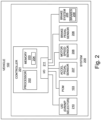
- FIG. 2 A schematic diagram of a system 200 for automatically causing brakes 209 of the vehicle 100 to be applied to hold the vehicle 100 stationary is shown in Fig. 2 .
- the system 200 comprises a controller 201.
- the controller 201 comprises an electronic processor 202 and an electronic memory device 203 having instructions 204 stored therein.
- the electronic processor 202 is electrically coupled to the electronic memory device 203 and it is configured to access the electronic memory device 203 and execute the instructions 204, to cause the controller 201 to perform the processes that will be described below.
- the controller 201 comprises input/output means 211 to enable signals to be received by the controller 201 from other components of the vehicle 100 and to enable the controller 201 to transmit signals to other components of the vehicle 100.
- the input/output means 211 may be provided by a transceiver configured to enable communication over a data bus.
- the controller 201 is configured to receive signals from a brake pedal sensor 206 configured to detect pressure being applied to the brake pedal 109 and provide a signal to the controller 201 indicative of whether or not the brake pedal 109 has been pressed.
- the controller 201 is also configured to receive signals indicative of whether or not the driver of the vehicle 100 is requesting torque by depression of the accelerator pedal 108. In the present embodiment, these signals are received from an accelerator pedal sensor 207 configured to detect the position of the accelerator pedal 108 and provide signals indicative of depression or release of the accelerator pedal 108 to the controller 201.
- the controller 201 is also configured to receive signals from a motor speed sensor 208 indicative of the rotational velocity of the electric motor 102, which is also indicative of the speed of the vehicle 100. Due to the gear ratio of the transmission system 104, the electric motor 102 turns many times for each revolution of the driven wheels 101. Consequently, measurement of the rotational velocity of the electric motor 102 provides a very accurate indication of speed of the vehicle 100, even at very low speeds of the vehicle 100. This enables the controller 201 to determine from the received signals when the vehicle 100 is stationary with a relatively small measurement error.
- speed generally refers to a scalar quantity equal to the magnitude of a velocity, and therefore it is always positive.
- speed of the vehicle “measured speed” or “vehicle speed” as used herein refers to a scalar quantity with a positive sign for forward motion of the vehicle 100 and a negative sign for backward motion of the vehicle.
- the vehicle 100 comprises a user input device 210 configured to enable a user to select a direction of travel, i.e. drive or reverse (D or R), or alternatively neutral or park (N or P).
- the controller 201 is configured to receive signals indicative of whether a direction of travel is currently selected. In the present embodiment the indication of the selected direction of travel is received from the user input device 210 but in alternative embodiments it may be received from the powertrain control module 103.
- the controller 201 is configured to provide output signals to a brake system 205 to cause the brakes 209 of the vehicle 100 to be applied to hold the vehicle 100 stationary.
- the brake system 205 may be an antilock braking system.
- the output signals are provided by the controller 201 in dependence on the indications of speed received from the motor speed sensor 208 and a determination that the gradient on which the vehicle 100 is positioned is less than a threshold gradient.
- the controller 201 determines that the gradient is less than a threshold gradient when the magnitude of the speed of the vehicle 100 is less than a threshold speed throughout a predefined period of time.
- the threshold speed may be set at 1 kilometre per hour.
- the threshold speed is dependent on the direction of movement of the vehicle 100, but in either case the controller 201 determines that the gradient is less than a threshold gradient when the speed of the vehicle 100 remains within a first range of speeds that includes zero during the predefined period.
- the first range is from -1 kilometer per hour to +1 kilometer per hour.
- the time at which the output signal is provided by the controller 201 depends on whether the brake pedal sensor 206 indicates that the brake pedal 109 is depressed and/or the accelerator pedal sensor 208 indicating that the accelerator pedal 108 is depressed.
- the powertrain control module 103 has a creep function that causes the motor 102 to provide a small amount of torque when drive is selected and the accelerator pedal is not depressed.
- the creep function may be switched on or off by a user input device, and the controller is only configured to automatically cause the brakes to be applied, when the creep function is switched off.
- the vehicle 100 has a driver assist function, such as an autonomous cruise control system, and a user input device to enable a user to switch on or off the driver assist function.
- the controller 201 is only configured to automatically cause the brakes to be applied, when the driver assist function is switched off.
- FIG. 3 A functional flow block diagram illustrating operations performed by the controller 201 is shown in Fig. 3 .
- the controller 201 is configured to receive the measured speed of the vehicle 100 and perform a low speed detection function 301 to detect when the speed of the vehicle 100 is within a first range of speeds that includes zero. When the measured speed is within the first range of speeds, an indication of this is provided to a first timer 302 and also to a second timer 303.
- the first timer 302 and the second timer 303 are arranged to start only when they receive an indication that the measured speed is within the first range of speeds and that the drive or reverse directions of travel have been selected by the driver. If the measured speed goes outside of the first range of speeds and/or the drive or reverse are deselected, the timers 302 and 303 are stopped and reset.
- the first timer 302 times a first period that has a predefined first duration and the second timer times a second period having a predefined second duration that is longer than the predefined first duration.
- the predefined first duration is about 2 seconds.
- the first timer 302 is arranged to provide an output to indicate when the first period has expired and the output is maintained by the first timer 302 while ever the measured speed remains within the first range of speeds and the drive/reverse selection is maintained.
- the second timer 303 provides an output to indicate when the second period has expired and the output is maintained by the second timer while ever the measured speed remains within the first range of speeds and the drive/reverse selection is maintained.
- the controller 201 is also configured to perform a zero speed detection function 304 in which the measured speeds received by the controller 201 are compared to a second range of speeds that includes zero.
- the second range of speeds is substantially smaller than the first range of speeds and is typically arranged to be approximately equal to zero plus or minus the measurement accuracy of the motor speed sensor 208.
- the second range of speeds may be from -0.1 to +0.1 kilometres per hour, or even smaller.
- the zero speed detection function 304 is configured to provide an output indicating that the vehicle 100 is stationary when a measured speed is within the second range of speeds.
- the measured speed changes from a positive value to a negative value indicating that the speed of the vehicle 100 has crossed zero.
- the measured speed changes from a negative value to a positive value indicating that the speed of the vehicle 100 has crossed zero.
- the zero speed detection function 304 is also configured to detect when the speed of the vehicle 100 has crossed zero and provide an indication that the vehicle 100 is stationary when this is detected.
- the controller 201 is configured to provide an output signal 305 to the brake system 205 to request that the brake system 205 to apply the brakes 209 to hold the vehicle 100 stationary.
- the request for brakes to be applied is latched until any one of a second set of requirements is met.
- the second set of requirements may comprise: the brake system 205 confirming that the brakes 209 have been applied; selection of neutral (rather than drive or reverse); confirmation that the park pawl is engaged when park is selected (rather than drive or reverse); a driver pressing the accelerator pedal to cause the vehicle to be moved in the selected direction of travel; a driver pressing the brake pedal, which indicates that the driver is taking control of the vehicle; creep function or a driver assist function being switched on.
- the controller 201 is also configured to receive a signal from the accelerator pedal sensor 208 indicative of when the accelerator pedal 108 is being depressed, and, in the present embodiment, receive a signal from the brake pedal sensor 206 indicative of when the brake pedal 109 is being depressed.
- the controller 201 comprises a pedal release timer 306 arranged to: start when these signals both indicate that the pedals 108 and 109 have gone from a pressed state to a released state; and stop and reset when the signals indicate that either of the pedals 108 and 109 has gone from a released state to a pressed state.
- the pedal release timer 306 is configure to provide an output when the period from it being started exceeds a predefined pedal release duration, and to maintain the output while ever both the accelerator pedal 108 and the brake pedal 109 continue to be released.
- the predefined pedal release duration is about 0.5 seconds.
- the controller 201 is also configured to provide a low torque detection function 306, in which a received signal indicating the current powertrain torque demand is compared to a small threshold value and to indicate when the powertrain torque demand is low, i.e. less than that threshold value.
- the controller 201 is configured to provide an output signal 305 to the brake system 205 to cause the brake system 205 to apply the brakes 209 to hold the vehicle 100 stationary when: the first timer 302 provides an output indicating that the first period of first duration has been exceeded; the zero speed detection function 304 indicates that the vehicle 100 is stationary; the pedal release timer 306 indicates that the pedals 108 and 109 have been released for at least the predefined pedal release duration; and the low torque detection function 307 indicates that the powertrain torque demand is low.
- the controller 201 is configured to automatically provide an output signal 305 to the brake system 205 to cause the brake system 205 to apply the brakes 209 to hold the vehicle 100 stationary, after a period of time of defined duration has elapsed beginning when the measured speed is within the first range of speeds. If the powertrain torque demand is low, and the accelerator pedal 108 and the brake pedal 109 are both released, the output signal 305 may be provided after a relatively short first period of time measured by the first timer 302. Alternatively, if either of the pedals 108 and 109 is depressed and/or the torque demand of the powertrain is high, the output signal 305 may be provided only after a relatively longer second period of time measured by the second timer 303.
- the brake pedal 109 and accelerator pedal 108 are both released and the speed of the vehicle 100 remains less than a threshold speed for the duration of the first period, timed by the first timer 302, this indicates that the gradient on which the vehicle 100 is positioned is less than a threshold gradient. i.e. if the vehicle 100 were on a steeper slope it would accelerate more rapidly and its speed would not remain within the first range of speeds used by the low speed detection function 301 for the whole period measured by the first timer 302.
- the controller 201 is configured to receive a signal from a gradient sensing means which may comprise an inertial measurement unit.
- the gradient sensing means or the controller 201 may be configured to determine when the gradient measured by the gradient sensing means is less than a predefined threshold gradient.
- the controller 201 may then be arranged to provide the output signal 305 to the brake system 205 when: the sensed gradient is below the threshold gradient; the measured speed is below a threshold speed (or within a first range); and a direction of travel (drive/reverse) is selected. Therefore, in such an embodiment, the first timer 302 is not necessary. It will be understood that the implementation of the second timer is also optional.
- the second timer 303 is omitted and the controller 201 only provides an output signal when: the first timer 302 has exceeded its predefined duration; the measured speed remains within the first range; the measured speed has been zero or crossed zero since the first timer was started; a direction of travel (drive/reverse) is selected; and at least the accelerator pedal is not depressed.
- the first timer 302 is omitted and the controller 201 only provides an output signal when: the second timer 303 has exceeded its predefined duration; the measured speed remains within the first range; the measured speed has been zero or crossed zero since the second timer 303 was started; and a direction of travel (drive/reverse) is selected.
- the controller 201 may not include the zero speed detection function 304 and it may be configured to provide the output signal 305 whenever drive or reverse are selected and either the second timer 303 has timed out or the first timer 302 and the pedal release timer 306 have timed out.
- the pedal release timer 306 is started in dependence on receiving an indication of the accelerator pedal 108 being released and does not depend on the brake pedal 109 being released.
- Graphs illustrating some examples of the behavior of the controller 201 are shown in Figs. 4 to 7 .
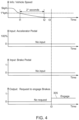
- Each one of Figs. 4 to 7 shows four graphs with time along the horizontal axis. Along the vertical axis the graphs show, from top graph to bottom graph: vehicle speed; accelerator pedal pressure; brake pedal pressure; and the output signal 305 from the controller 201 to the brake system 205 to request application of the brakes 209.
- the vehicle 100 is slowing down from a speed of 5 kilometres per hour.
- the first timer 302 is started and it continues to run as the speed remains below the 1 kilometre per hour threshold speed.
- the first timer exceeds its predefined first duration, in this case 2 seconds, and the vehicle 100 is still not stationary. Consequently, in terms of Fig. 3 , the zero speed detection function 304 has not yet provided a necessary output to enable the controller 201 to provide its output signal 305 to the brake system 205.
- the zero speed detection function 304 Shortly after t2, at time t3 the vehicle 100 becomes stationary as determined by the zero speed detection function 304.
- the brake pedal 109 and the accelerator pedal 108 are never depressed during this example, and therefore when the vehicle 100 becomes stationary at t3, the controller 201 provides an output signal 305 to request the brake system 205 to apply the brakes 209.
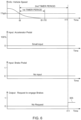
- the vehicle 100 is slowing down from a speed of 5 kilometres per hour.
- the first timer 302 is started and it continues to run as the speed remains below the 1 kilometre per hour threshold speed.
- the speed goes through 0 kilometres per hour and becomes negative as the vehicle 100 rolls backwards in the opposite direction to its initial direction of travel. Therefore, in terms of Fig. 3 , the zero speed detection function 304 detects that the speed has crossed zero at time t5 and provides an output signal to indicate this.
- the controller 201 provides an output signal 305 at time t6.
- the graphs illustrate the vehicle 100 slowing down on an uphill gradient while a small input is received at the accelerator pedal 108.
- the speed of the vehicle 100 goes below a threshold speed of the 1 kilometre per hour at time t8 and the first and second timers 302 and 303 are started.
- the speed then becomes at time t9, and remains at 0 kilometres per hour because the torque generated by the electric motor 102 is just sufficient to hold the vehicle 100 stationary on the uphill gradient.
- t9 at t10, which is 2 seconds after time t8, the first timer 302 times out but the controller 201 is unable to provide an output signal 305 to the brake system 205 because the driver is still pressing the accelerator pedal 108 to keep the vehicle 100 stationary.
- the second timer 303 times out and consequently the controller 201 provides the output signal 305 to the brake system.
- Fig. 7 the vehicle 100 is slowing down while a small input is received at the accelerator pedal.
- the speed of the vehicle 100 goes below a threshold speed of the 1 kilometre per hour at time t12, but it never becomes stationary. Consequently in terms of Fig. 3 , the zero speed detection function 304 does not provide an output indicating that the vehicle 100 is stationary and so the controller 201 is not enabled to provide an output signal 305. The driver is therefore able to drive the vehicle 100 at very low speeds without interference of automatic brake application.
- FIG. 8 A flowchart illustrating a method 800 performable by the controller 201 is shown in Fig. 8 .
- an indication of measured speed of the vehicle 100 is received.
- FIG. 9 A flowchart illustrating a second method 900 performable by the controller 201 is shown in Fig. 9 , in which the determination that the gradient is less than a threshold gradient is achieved by monitoring speed of the vehicle 100.
- an indication of measured speed of the vehicle 100 is received.
- a first timer is started at block 903 and another indication of measured speed is received at block 904.
- block 905 it is determined if the measured speed is still in the first range and if it is not the processes at blocks 901 and 902 are repeated until the speed is once again in the first range.
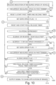
- FIG. 10 A flowchart illustrating a third method 1000 performable by the controller 201 is shown in Figs. 10 and 11 .
- an indication of measured speed of the vehicle 1000 is received.
- a first timer 302 and a second timer 303 are reset and started at block 1003 and a zero speed flag is reset to zero at block 1004.
- a pedal release timer 306 is then reset to zero and started at block 1005.
- the method returns to block 1001. If the current measured speed is still in the range, then at block 1011 it is determined whether the zero speed flag is set to 1. If it is, then it is determined at block 1012 whether the pedal release timer 306 has exceeded a pedal timer duration, i.e. it is determined whether a predefined pedal release period (for example, with a duration of 0.5 seconds) has elapsed since the pedal release timer 306 was started at block 1005. If it has, then it is determined at block 1013 whether the first timer has exceeded a first duration. If it has, then an output signal is provided at block 1014, for example to the brake system 206 to cause application of brakes 209.
- a pedal timer duration i.e. it is determined whether a predefined pedal release period (for example, with a duration of 0.5 seconds) has elapsed since the pedal release timer 306 was started at block 1005. If it has, then it is determined at block 1013 whether the first timer has exceeded a first duration. If it has, then an output
- the method 1000 simply returns to block 1001.
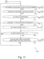
- a process at block 1015 is performed, which is shown on Fig. 11 .
- the zero speed flag is set to 1 and, if it is, it is determined at block 1021 if the second timer 303 has exceed a second duration. As mentioned above, the second duration is longer than the first duration. If the second timer 303 has exceeded the second duration, then the output is provided at block 1014 to cause the brakes 209 to be applied. If the processes at blocks 1020 or 1021 provide a negative result, the method returns to block 1015 and the processes at blocks 1015 to 1020 and 1021 are repeated.
- the pedal release timer 306 is reset and started at block 1005 (shown in Fig. 10 ) and the method 1000 may continue with the processes of blocks 1006 to 1014 as described above.
- the expiry of the pedal release timer 306 may be all that is still required for the output signal to be provided at block 1014. Therefore, for example, if the pedal timer duration is 0.5 seconds, then the brakes 209 may be automatically applied in accordance with block 1014, 0.5 seconds after the pedals are released.
- controller(s) described herein can each comprise a control unit or computational device having one or more electronic processors.
- a vehicle and/or a system thereof may comprise a single control unit or electronic controller or alternatively different functions of the controller(s) may be embodied in, or hosted in, different control units or controllers.
- a set of instructions could be provided which, when executed, cause said controller(s) or control unit(s) to implement the control techniques described herein (including the described method(s)).
- the set of instructions may be embedded in one or more electronic processors, or alternatively, the set of instructions could be provided as software to be executed by one or more electronic processor(s).
- a first controller may be implemented in software run on one or more electronic processors, and one or more other controllers may also be implemented in software run on or more electronic processors, optionally the same one or more processors as the first controller. It will be appreciated, however, that other arrangements are also useful.
- the set of instructions described above may be embedded in a computer-readable storage medium (e.g., a non-transitory computer-readable storage medium) that may comprise any mechanism for storing information in a form readable by a machine or electronic processors/computational device, including, without limitation: a magnetic storage medium (e.g., floppy diskette); optical storage medium (e.g., CD-ROM); magneto optical storage medium; read only memory (ROM); random access memory (RAM); erasable programmable memory (e.g., EPROM or EEPROM); flash memory; or electrical or other types of medium for storing such information/instructions.
- a computer-readable storage medium e.g., a non-transitory computer-readable storage medium
- a magnetic storage medium e.g., floppy diskette
- optical storage medium e.g., CD-ROM
- magneto optical storage medium e.g., magneto optical storage medium
- ROM read only memory
- RAM random access memory
- the blocks illustrated in the Figs. 8 to 11 may represent steps in a method and/or sections of code in the computer program 204.
- the illustration of a particular order to the blocks does not necessarily imply that there is a required or preferred order for the blocks and the order and arrangement of the block may be varied. Furthermore, it may be possible for some steps to be omitted.
Landscapes
- Engineering & Computer Science (AREA)
- Transportation (AREA)
- Mechanical Engineering (AREA)
- Automation & Control Theory (AREA)
- Physics & Mathematics (AREA)
- Mathematical Physics (AREA)
- Chemical & Material Sciences (AREA)
- Combustion & Propulsion (AREA)
- Regulating Braking Force (AREA)
- Electric Propulsion And Braking For Vehicles (AREA)
Claims (15)
- Steuerung (201) für ein Fahrzeug (100), wobei die Steuerung (201) konfiguriert ist zum:Empfangen einer Angabe einer gemessenen Geschwindigkeit des Fahrzeugs (100);Bestimmen, ob ein Gradient, auf dem sich das Fahrzeug (100) befindet, unterhalb eines Schwellengradienten liegt; undBereitstellen eines Ausgangssignals, um zu bewirken, dass eine Bremse (209) des Fahrzeugs (100) automatisch angewendet wird, um das Fahrzeug (100) stationär zu halten, in Abhängigkeit von:der empfangenen Angabe der gemessenen Geschwindigkeit des Fahrzeugs (100), die unter einer Schwellengeschwindigkeit liegt; undder Bestimmung, dass der Gradient unter dem Schwellengradienten liegt,dadurch gekennzeichnet, dass die Steuerung (201) konfiguriert ist, um Angaben eines Herunterdrückens von mindestens einem von dem Benutzer betätigbaren Pedals (108, 109) empfängt und in Abhängigkeit davon, dass das mindestens eine von dem Benutzer betätigbare Pedal (108, 109) heruntergedrückt wird, Bereitstellen des Ausgangssignals, um zu bewirken, dass die Bremse (209) des Fahrzeugs (100) nur nach dem Ablauf einer ersten Zeitperiode, die eine erste Dauer aufweist, in der die Angabe der gemessenen Geschwindigkeit innerhalb eines ersten Geschwindigkeitsbereichs einschließlich Null liegt, automatisch angewendet wird.
- Steuerung (201) nach Anspruch 1, wobei die Steuerung (201) konfiguriert ist, um zu bestimmen, ob der Gradient unter dem Schwellengradienten liegt, durch Überwachen der Angabe der gemessenen Geschwindigkeit des Fahrzeugs (100) über eine zweite Zeitperiode.
- Steuerung (201) nach Anspruch 1, wobei die Steuerung (201) konfiguriert ist, um zu bestimmen, ob der Gradient unter dem Schwellengradienten liegt, durch Bestimmen, ob die gemessene Geschwindigkeit des Fahrzeugs (100) innerhalb des ersten Geschwindigkeitsbereichs für eine zweite Zeitperiode, die eine vordefinierte zweite Dauer aufweist, verbleibt.
- Steuerung (201) nach Anspruch 3, wobei die Steuerung (201) konfiguriert ist, um das Ausgangssignal bereitzustellen, um zu bewirken, dass die Bremse (209) des Fahrzeugs (100) nach dem Ablauf der zweiten Zeitperiode mit der vordefinierten zweiten Dauer, nur nachdem eine vordefinierte Löseperiode des Pedals (108, 109) verstrichen ist, während der das mindestens eine von dem Benutzer betätigbare Pedal (108, 109) nicht heruntergedrückt ist, automatisch angewendet wird.
- Steuerung (201) nach einem der Ansprüche 3 oder 4, wobei die Steuerung (201) konfiguriert ist, um das Ausgangssignal in Abhängigkeit von mindestens einem bereitzustellen von:der gemessenen Geschwindigkeit des Fahrzeugs (100), die seit dem Beginn der zweiten Zeitperiode null überschritten hat,der gemessenen Geschwindigkeit des Fahrzeugs (100), die innerhalb eines zweiten Bereichs lag, der kleiner als der erste Bereich ist, und der seit dem Beginn der ersten Zeitperiode null einschließt, oderder gemessenen Geschwindigkeit des Fahrzeugs (100), die seit dem Beginn der ersten Zeitperiode entweder null überschritten hat oder null war.
- Steuerung (201) nach einem der vorstehenden Ansprüche, wobei die vordefinierte erste Dauer der ersten Zeitperiode länger als die vordefinierte zweite Dauer der zweiten Zeitperiode ist.
- Steuerung (201) nach einem der vorstehenden Ansprüche, wobei die Steuerung (201) konfiguriert ist zum: Empfangen von Angaben von Drehmomentbedarf; und Bereitstellen eines Ausgangssignals, um zu bewirken, dass die Bremse (209) des Fahrzeugs (100) nur nach dem Ablauf der zweiten Zeitperiode in Abhängigkeit von dem Empfangen einer Angabe eines empfangenen Drehmomentbedarfs automatisch angewendet wird.
- Steuerung (201) nach einem der Ansprüche 1 bis 7, wobei die Steuerung (201) konfiguriert ist zum: Empfangen einer Angabe einer ausgewählten Fahrtrichtung; und Bereitstellen des Ausgangssignals nur wenn die Angabe empfangen wird.
- Steuerung (201) nach einem der Ansprüche 1 bis 8, wobei die Steuerung (201) eine elektronische Speichervorrichtung (203), und die darin gespeicherte Anweisungen (204) aufweist, umfasst; und einen elektronischen Prozessor (202), der mit der elektronischen Speichervorrichtung (203) elektrisch gekoppelt und konfiguriert ist, um auf die elektronische Speichervorrichtung (203) zuzugreifen und die Anweisungen (204) auszuführen.
- System (200), umfassend die Steuerung (201) nach einem der Ansprüche 1 bis 9 und ein Bremssystem (205), das konfiguriert ist, um eine Bremse (209) in Abhängigkeit von dem Empfangen des Ausgangssignals von der Steuerung (201) anzuwenden.
- Fahrzeug (100), umfassend die Steuerung (201) nach einem der Ansprüche 1 bis 9 oder das System (200) nach Anspruch 10.
- Verfahren (1000) zum Steuern der Anwendung einer Bremse (209) an einem Fahrzeug (100), das Verfahren (1000) umfassend:Empfangen (1001) einer Angabe einer gemessenen Geschwindigkeit des Fahrzeugs (100);Bestimmen (1013), ob ein Gradient, auf dem sich das Fahrzeug (100) befindet, unterhalb eines Schwellengradienten liegt; undBewirken (1014), dass eine Bremse (209) des Fahrzeugs (100) angewendet wird, um das Fahrzeug (100) stationär zu halten, in Abhängigkeit von: der empfangenen Angabe der gemessenen Geschwindigkeit des Fahrzeugs (100), die unter einer Schwellengeschwindigkeit liegt; und der Bestimmung, dass der Gradient unter dem Schwellengradienten liegt,dadurch gekennzeichnet, dass das Verfahren (1000) das Empfangen von Angaben des Herunterdrückens von mindestens einem von dem Benutzer betätigbaren Pedals (108, 109) empfängt und in Abhängigkeit davon, dass das mindestens eine von dem Benutzer betätigbare Pedal (108, 109) heruntergedrückt wird, Bewirken, dass die Bremse (209) des Fahrzeugs (100) nur nach dem Ablauf einer ersten Zeitperiode, die eine erste vordefinierte Dauer aufweist, in der die Angabe der gemessenen Geschwindigkeit innerhalb eines ersten Geschwindigkeitsbereichs einschließlich Null liegt, automatisch angewendet wird.
- Verfahren (1000) nach Anspruch 12, wobei das Bestimmen, ob der Gradient unter dem Schwellengradienten liegt, mindestens eines umfasst von:Überwachen der Angabe der gemessenen Geschwindigkeit des Fahrzeugs (100) über eine erste Zeitperiode oderBestimmen, ob die gemessene Geschwindigkeit des Fahrzeugs (100) innerhalb des ersten Geschwindigkeitsbereichs für eine zweite Zeitperiode, die eine vordefinierte zweite Dauer aufweist, verbleibt.
- Computerprogramm, das, wenn es durch einen Prozessor (202) ausgeführt wird, bewirkt, dass der Prozessor (202) das Verfahren (1000) nach einem der Ansprüche 12 oder 13 durchführt.
- Nichtflüchtiges computerlesbares Speichermedium, das Anweisungen (204) aufweist, die darin gespeichert sind, die, wenn sie auf einem Prozessor (202) ausgeführt werden, bewirken, dass der Prozessor (202) das Verfahren (1000) nach einem der Ansprüche 12 oder 13 durchführt.
Applications Claiming Priority (3)
| Application Number | Priority Date | Filing Date | Title |
|---|---|---|---|
| GB1803014.8A GB2571322B (en) | 2018-02-26 | 2018-02-26 | A controller for a vehicle and a method |
| EP19706382.9A EP3758996B1 (de) | 2018-02-26 | 2019-01-29 | Steuerung für ein fahrzeug und verfahren |
| PCT/EP2019/052043 WO2019162046A1 (en) | 2018-02-26 | 2019-01-29 | A controller for a vehicle and a method |
Related Parent Applications (2)
| Application Number | Title | Priority Date | Filing Date |
|---|---|---|---|
| EP19706382.9A Division EP3758996B1 (de) | 2018-02-26 | 2019-01-29 | Steuerung für ein fahrzeug und verfahren |
| EP19706382.9A Division-Into EP3758996B1 (de) | 2018-02-26 | 2019-01-29 | Steuerung für ein fahrzeug und verfahren |
Publications (2)
| Publication Number | Publication Date |
|---|---|
| EP4339050A1 EP4339050A1 (de) | 2024-03-20 |
| EP4339050B1 true EP4339050B1 (de) | 2025-06-04 |
Family
ID=61903291
Family Applications (2)
| Application Number | Title | Priority Date | Filing Date |
|---|---|---|---|
| EP19706382.9A Active EP3758996B1 (de) | 2018-02-26 | 2019-01-29 | Steuerung für ein fahrzeug und verfahren |
| EP23206807.2A Active EP4339050B1 (de) | 2018-02-26 | 2019-01-29 | Steuerung für ein fahrzeug und verfahren |
Family Applications Before (1)
| Application Number | Title | Priority Date | Filing Date |
|---|---|---|---|
| EP19706382.9A Active EP3758996B1 (de) | 2018-02-26 | 2019-01-29 | Steuerung für ein fahrzeug und verfahren |
Country Status (5)
| Country | Link |
|---|---|
| US (2) | US11745708B2 (de) |
| EP (2) | EP3758996B1 (de) |
| CN (2) | CN111770862B (de) |
| GB (1) | GB2571322B (de) |
| WO (1) | WO2019162046A1 (de) |
Families Citing this family (3)
| Publication number | Priority date | Publication date | Assignee | Title |
|---|---|---|---|---|
| JP7133752B2 (ja) * | 2018-03-28 | 2022-09-09 | 株式会社アドヴィックス | 走行制御装置 |
| KR20220166415A (ko) * | 2021-06-10 | 2022-12-19 | 현대자동차주식회사 | 전자식 주차 브레이크 시스템의 제어 방법 |
| US12221105B2 (en) * | 2022-08-22 | 2025-02-11 | Arvinmeritor Technology, Llc | System and method of controlling torque provided with an axle assembly |
Family Cites Families (17)
| Publication number | Priority date | Publication date | Assignee | Title |
|---|---|---|---|---|
| JP2001287632A (ja) * | 2000-04-05 | 2001-10-16 | Toyota Central Res & Dev Lab Inc | 制動力制御装置 |
| JP2005271822A (ja) * | 2004-03-25 | 2005-10-06 | Mitsubishi Fuso Truck & Bus Corp | 車両の自動減速制御装置 |
| DE102005046015A1 (de) * | 2004-09-28 | 2006-04-13 | Continental Teves Ag & Co. Ohg | Verfahren zum Durchführen eines Bremsvorgangs und Bremsvorrichtung |
| FR2927040B1 (fr) * | 2008-02-05 | 2010-04-16 | Renault Sas | Procede de fonctionnement d'un systeme d'assistance au demarrage d'un vehicule automobile en cote |
| KR101230903B1 (ko) * | 2010-12-08 | 2013-02-07 | 현대자동차주식회사 | 전기자동차의 등판밀림방지를 위한 크립토크 제어 방법 |
| JP5168416B2 (ja) * | 2011-02-18 | 2013-03-21 | トヨタ自動車株式会社 | 車両用制御システム |
| JP5853690B2 (ja) * | 2011-12-28 | 2016-02-09 | 日産自動車株式会社 | 車両のエンジン自動停止制御装置 |
| WO2014027111A1 (en) * | 2012-08-16 | 2014-02-20 | Jaguar Land Rover Limited | Vehicle speed control system |
| US8793035B2 (en) * | 2012-08-31 | 2014-07-29 | Ford Global Technologies, Llc | Dynamic road gradient estimation |
| US9454508B2 (en) * | 2012-08-31 | 2016-09-27 | Ford Global Technologies, Llc | Kinematic road gradient estimation |
| US9126597B2 (en) * | 2013-03-14 | 2015-09-08 | Robert Bosch Gmbh | Hill hold decay |
| US9151383B2 (en) * | 2013-05-29 | 2015-10-06 | Fca Us Llc | Interactive transmission shift techniques |
| GB2523177B (en) * | 2014-02-18 | 2017-05-10 | Jaguar Land Rover Ltd | Vehicle movement on an inclined surface |
| GB2527512A (en) * | 2014-06-23 | 2015-12-30 | Jaguar Land Rover Ltd | Control of a multi-speed vehicle transmission |
| SE539496C2 (en) * | 2014-10-29 | 2017-10-03 | Scania Cv Ab | Method and system for decelerating a vehicle |
| CN106143474B (zh) | 2015-03-25 | 2019-02-26 | 比亚迪股份有限公司 | 混合动力汽车及其驱动控制方法和装置 |
| JP6694405B2 (ja) * | 2017-03-17 | 2020-05-13 | 本田技研工業株式会社 | 輸送機器の制御装置 |
-
2018
- 2018-02-26 GB GB1803014.8A patent/GB2571322B/en active Active
-
2019
- 2019-01-29 CN CN201980015057.XA patent/CN111770862B/zh active Active
- 2019-01-29 CN CN202311387399.9A patent/CN117416351A/zh active Pending
- 2019-01-29 WO PCT/EP2019/052043 patent/WO2019162046A1/en not_active Ceased
- 2019-01-29 EP EP19706382.9A patent/EP3758996B1/de active Active
- 2019-01-29 EP EP23206807.2A patent/EP4339050B1/de active Active
- 2019-01-29 US US16/971,217 patent/US11745708B2/en active Active
-
2023
- 2023-07-14 US US18/352,782 patent/US12233838B2/en active Active
Also Published As
| Publication number | Publication date |
|---|---|
| CN111770862B (zh) | 2023-11-10 |
| GB2571322B (en) | 2020-05-27 |
| US20210101574A1 (en) | 2021-04-08 |
| CN111770862A (zh) | 2020-10-13 |
| WO2019162046A1 (en) | 2019-08-29 |
| EP4339050A1 (de) | 2024-03-20 |
| US12233838B2 (en) | 2025-02-25 |
| EP3758996A1 (de) | 2021-01-06 |
| EP3758996B1 (de) | 2023-12-06 |
| GB201803014D0 (en) | 2018-04-11 |
| GB2571322A (en) | 2019-08-28 |
| US20240017706A1 (en) | 2024-01-18 |
| US11745708B2 (en) | 2023-09-05 |
| CN117416351A (zh) | 2024-01-19 |
Similar Documents
| Publication | Publication Date | Title |
|---|---|---|
| US12233838B2 (en) | Controller for a vehicle and method | |
| US8396641B2 (en) | Inter-vehicle distance control device | |
| KR101475687B1 (ko) | 자동차를 위한 경사로 출발 보조 방법 | |
| US10202121B2 (en) | Stop control device | |
| EP2266856A1 (de) | Bestimmung der Fahrtrichtung eines Fahrzeugs bei langsamer Geschwindigkeit | |
| US20100262329A1 (en) | System and method for controlling the release of an automatic parking brake device onboard an automobile | |
| CN112339559A (zh) | 车辆控制装置以及车辆控制方法 | |
| KR101795130B1 (ko) | 전기 자동차의 크립주행 제어 장치 및 그 방법 | |
| US20060170284A1 (en) | Driving assistance function for a vehicle stationary on a slope | |
| CN103523016A (zh) | 用于在滑行期间运行车辆的方法 | |
| WO2007039810A1 (en) | Deceleration control apparatus and method for vehicle | |
| JP2005507823A (ja) | 自動車の縦ガイド装置 | |
| US20080087509A1 (en) | Method and Device for Actuating a Braking System, in Particular a Parking Brake of a Motor Vehicle | |
| EP3758995B1 (de) | Steuerung und verfahren zur steuerung der geschwindigkeit eines fahrzeugs | |
| SE1150846A1 (sv) | Metod, och en regleranordning, i samband med aktivering av hill-hold-funktionen för ett fordon | |
| JP2011240927A (ja) | 車間距離制御装置 | |
| JP2000149161A (ja) | 車両の制御装置 | |
| JP5169539B2 (ja) | 降坂路走行速度制御装置 | |
| WO2026000736A1 (zh) | 驻车制动控制方法、控制装置、车辆及存储介质 | |
| US7917273B2 (en) | Driving assistance function on following a queue of vehicles | |
| WO2012017513A1 (ja) | 車両用情報処理装置 | |
| JP4534840B2 (ja) | ブレーキ制御装置 | |
| CN121492869A (zh) | 用于线控车辆的自动静止保持与防溜车控制方法及装置 | |
| CN117698693A (zh) | 自动泊车控制方法和装置 |
Legal Events
| Date | Code | Title | Description |
|---|---|---|---|
| PUAI | Public reference made under article 153(3) epc to a published international application that has entered the european phase |
Free format text: ORIGINAL CODE: 0009012 |
|
| STAA | Information on the status of an ep patent application or granted ep patent |
Free format text: STATUS: THE APPLICATION HAS BEEN PUBLISHED |
|
| AC | Divisional application: reference to earlier application |
Ref document number: 3758996 Country of ref document: EP Kind code of ref document: P |
|
| AK | Designated contracting states |
Kind code of ref document: A1 Designated state(s): AL AT BE BG CH CY CZ DE DK EE ES FI FR GB GR HR HU IE IS IT LI LT LU LV MC MK MT NL NO PL PT RO RS SE SI SK SM TR |
|
| P01 | Opt-out of the competence of the unified patent court (upc) registered |
Free format text: CASE NUMBER: APP_33577/2024 Effective date: 20240605 |
|
| STAA | Information on the status of an ep patent application or granted ep patent |
Free format text: STATUS: REQUEST FOR EXAMINATION WAS MADE |
|
| 17P | Request for examination filed |
Effective date: 20240920 |
|
| RBV | Designated contracting states (corrected) |
Designated state(s): AL AT BE BG CH CY CZ DE DK EE ES FI FR GB GR HR HU IE IS IT LI LT LU LV MC MK MT NL NO PL PT RO RS SE SI SK SM TR |
|
| RIC1 | Information provided on ipc code assigned before grant |
Ipc: B60W 40/076 20120101ALI20241128BHEP Ipc: B60W 30/18 20120101ALI20241128BHEP Ipc: B60W 10/18 20120101AFI20241128BHEP |
|
| GRAP | Despatch of communication of intention to grant a patent |
Free format text: ORIGINAL CODE: EPIDOSNIGR1 |
|
| STAA | Information on the status of an ep patent application or granted ep patent |
Free format text: STATUS: GRANT OF PATENT IS INTENDED |
|
| INTG | Intention to grant announced |
Effective date: 20250103 |
|
| GRAS | Grant fee paid |
Free format text: ORIGINAL CODE: EPIDOSNIGR3 |
|
| GRAA | (expected) grant |
Free format text: ORIGINAL CODE: 0009210 |
|
| STAA | Information on the status of an ep patent application or granted ep patent |
Free format text: STATUS: THE PATENT HAS BEEN GRANTED |
|
| AC | Divisional application: reference to earlier application |
Ref document number: 3758996 Country of ref document: EP Kind code of ref document: P |
|
| AK | Designated contracting states |
Kind code of ref document: B1 Designated state(s): AL AT BE BG CH CY CZ DE DK EE ES FI FR GB GR HR HU IE IS IT LI LT LU LV MC MK MT NL NO PL PT RO RS SE SI SK SM TR |
|
| REG | Reference to a national code |
Ref country code: GB Ref legal event code: FG4D |
|
| REG | Reference to a national code |
Ref country code: CH Ref legal event code: EP |
|
| REG | Reference to a national code |
Ref country code: DE Ref legal event code: R096 Ref document number: 602019070960 Country of ref document: DE |
|
| REG | Reference to a national code |
Ref country code: IE Ref legal event code: FG4D |
|
| REG | Reference to a national code |
Ref country code: NL Ref legal event code: MP Effective date: 20250604 |
|
| PG25 | Lapsed in a contracting state [announced via postgrant information from national office to epo] |
Ref country code: FI Free format text: LAPSE BECAUSE OF FAILURE TO SUBMIT A TRANSLATION OF THE DESCRIPTION OR TO PAY THE FEE WITHIN THE PRESCRIBED TIME-LIMIT Effective date: 20250604 Ref country code: ES Free format text: LAPSE BECAUSE OF FAILURE TO SUBMIT A TRANSLATION OF THE DESCRIPTION OR TO PAY THE FEE WITHIN THE PRESCRIBED TIME-LIMIT Effective date: 20250604 |
|
| REG | Reference to a national code |
Ref country code: LT Ref legal event code: MG9D |
|
| PG25 | Lapsed in a contracting state [announced via postgrant information from national office to epo] |
Ref country code: GR Free format text: LAPSE BECAUSE OF FAILURE TO SUBMIT A TRANSLATION OF THE DESCRIPTION OR TO PAY THE FEE WITHIN THE PRESCRIBED TIME-LIMIT Effective date: 20250905 Ref country code: NO Free format text: LAPSE BECAUSE OF FAILURE TO SUBMIT A TRANSLATION OF THE DESCRIPTION OR TO PAY THE FEE WITHIN THE PRESCRIBED TIME-LIMIT Effective date: 20250904 |
|
| PG25 | Lapsed in a contracting state [announced via postgrant information from national office to epo] |
Ref country code: PL Free format text: LAPSE BECAUSE OF FAILURE TO SUBMIT A TRANSLATION OF THE DESCRIPTION OR TO PAY THE FEE WITHIN THE PRESCRIBED TIME-LIMIT Effective date: 20250604 |
|
| PG25 | Lapsed in a contracting state [announced via postgrant information from national office to epo] |
Ref country code: BG Free format text: LAPSE BECAUSE OF FAILURE TO SUBMIT A TRANSLATION OF THE DESCRIPTION OR TO PAY THE FEE WITHIN THE PRESCRIBED TIME-LIMIT Effective date: 20250604 |
|
| PG25 | Lapsed in a contracting state [announced via postgrant information from national office to epo] |
Ref country code: HR Free format text: LAPSE BECAUSE OF FAILURE TO SUBMIT A TRANSLATION OF THE DESCRIPTION OR TO PAY THE FEE WITHIN THE PRESCRIBED TIME-LIMIT Effective date: 20250604 |
|
| PG25 | Lapsed in a contracting state [announced via postgrant information from national office to epo] |
Ref country code: RS Free format text: LAPSE BECAUSE OF FAILURE TO SUBMIT A TRANSLATION OF THE DESCRIPTION OR TO PAY THE FEE WITHIN THE PRESCRIBED TIME-LIMIT Effective date: 20250904 |
|
| PG25 | Lapsed in a contracting state [announced via postgrant information from national office to epo] |
Ref country code: LV Free format text: LAPSE BECAUSE OF FAILURE TO SUBMIT A TRANSLATION OF THE DESCRIPTION OR TO PAY THE FEE WITHIN THE PRESCRIBED TIME-LIMIT Effective date: 20250604 |
|
| PG25 | Lapsed in a contracting state [announced via postgrant information from national office to epo] |
Ref country code: NL Free format text: LAPSE BECAUSE OF FAILURE TO SUBMIT A TRANSLATION OF THE DESCRIPTION OR TO PAY THE FEE WITHIN THE PRESCRIBED TIME-LIMIT Effective date: 20250604 |
|
| PG25 | Lapsed in a contracting state [announced via postgrant information from national office to epo] |
Ref country code: PT Free format text: LAPSE BECAUSE OF FAILURE TO SUBMIT A TRANSLATION OF THE DESCRIPTION OR TO PAY THE FEE WITHIN THE PRESCRIBED TIME-LIMIT Effective date: 20251006 |
|
| REG | Reference to a national code |
Ref country code: AT Ref legal event code: MK05 Ref document number: 1800079 Country of ref document: AT Kind code of ref document: T Effective date: 20250604 |
|
| PG25 | Lapsed in a contracting state [announced via postgrant information from national office to epo] |
Ref country code: IS Free format text: LAPSE BECAUSE OF FAILURE TO SUBMIT A TRANSLATION OF THE DESCRIPTION OR TO PAY THE FEE WITHIN THE PRESCRIBED TIME-LIMIT Effective date: 20251004 |
|
| PG25 | Lapsed in a contracting state [announced via postgrant information from national office to epo] |
Ref country code: SM Free format text: LAPSE BECAUSE OF FAILURE TO SUBMIT A TRANSLATION OF THE DESCRIPTION OR TO PAY THE FEE WITHIN THE PRESCRIBED TIME-LIMIT Effective date: 20250604 Ref country code: AT Free format text: LAPSE BECAUSE OF FAILURE TO SUBMIT A TRANSLATION OF THE DESCRIPTION OR TO PAY THE FEE WITHIN THE PRESCRIBED TIME-LIMIT Effective date: 20250604 |
|
| PG25 | Lapsed in a contracting state [announced via postgrant information from national office to epo] |
Ref country code: CZ Free format text: LAPSE BECAUSE OF FAILURE TO SUBMIT A TRANSLATION OF THE DESCRIPTION OR TO PAY THE FEE WITHIN THE PRESCRIBED TIME-LIMIT Effective date: 20250604 |
|
| PG25 | Lapsed in a contracting state [announced via postgrant information from national office to epo] |
Ref country code: EE Free format text: LAPSE BECAUSE OF FAILURE TO SUBMIT A TRANSLATION OF THE DESCRIPTION OR TO PAY THE FEE WITHIN THE PRESCRIBED TIME-LIMIT Effective date: 20250604 |
|
| PG25 | Lapsed in a contracting state [announced via postgrant information from national office to epo] |
Ref country code: SK Free format text: LAPSE BECAUSE OF FAILURE TO SUBMIT A TRANSLATION OF THE DESCRIPTION OR TO PAY THE FEE WITHIN THE PRESCRIBED TIME-LIMIT Effective date: 20250604 |
|
| PG25 | Lapsed in a contracting state [announced via postgrant information from national office to epo] |
Ref country code: IT Free format text: LAPSE BECAUSE OF FAILURE TO SUBMIT A TRANSLATION OF THE DESCRIPTION OR TO PAY THE FEE WITHIN THE PRESCRIBED TIME-LIMIT Effective date: 20250604 |
|
| REG | Reference to a national code |
Ref country code: DE Ref legal event code: R097 Ref document number: 602019070960 Country of ref document: DE |
|
| PGFP | Annual fee paid to national office [announced via postgrant information from national office to epo] |
Ref country code: GB Payment date: 20260220 Year of fee payment: 8 |
|
| PLBE | No opposition filed within time limit |
Free format text: ORIGINAL CODE: 0009261 |
|
| STAA | Information on the status of an ep patent application or granted ep patent |
Free format text: STATUS: NO OPPOSITION FILED WITHIN TIME LIMIT |
|
| PG25 | Lapsed in a contracting state [announced via postgrant information from national office to epo] |
Ref country code: DK Free format text: LAPSE BECAUSE OF FAILURE TO SUBMIT A TRANSLATION OF THE DESCRIPTION OR TO PAY THE FEE WITHIN THE PRESCRIBED TIME-LIMIT Effective date: 20250604 |
|
| PGFP | Annual fee paid to national office [announced via postgrant information from national office to epo] |
Ref country code: DE Payment date: 20260121 Year of fee payment: 8 |
|
| REG | Reference to a national code |
Ref country code: CH Ref legal event code: L10 Free format text: ST27 STATUS EVENT CODE: U-0-0-L10-L00 (AS PROVIDED BY THE NATIONAL OFFICE) Effective date: 20260416 |
|
| PGFP | Annual fee paid to national office [announced via postgrant information from national office to epo] |
Ref country code: FR Payment date: 20260218 Year of fee payment: 8 |