EP4339041A1 - Gas generator - Google Patents
Gas generator Download PDFInfo
- Publication number
- EP4339041A1 EP4339041A1 EP22807428.2A EP22807428A EP4339041A1 EP 4339041 A1 EP4339041 A1 EP 4339041A1 EP 22807428 A EP22807428 A EP 22807428A EP 4339041 A1 EP4339041 A1 EP 4339041A1
- Authority
- EP
- European Patent Office
- Prior art keywords
- filter
- plate portion
- bottom plate
- housing
- gas generator
- Prior art date
- Legal status (The legal status is an assumption and is not a legal conclusion. Google has not performed a legal analysis and makes no representation as to the accuracy of the status listed.)
- Withdrawn
Links
- 238000002485 combustion reaction Methods 0.000 claims abstract description 57
- 229910052751 metal Inorganic materials 0.000 claims abstract description 18
- 239000002184 metal Substances 0.000 claims abstract description 18
- 230000004323 axial length Effects 0.000 claims abstract description 15
- 239000007789 gas Substances 0.000 description 203
- 239000003795 chemical substances by application Substances 0.000 description 55
- 230000004913 activation Effects 0.000 description 44
- 230000006835 compression Effects 0.000 description 40
- 238000007906 compression Methods 0.000 description 40
- 230000000052 comparative effect Effects 0.000 description 28
- 238000012795 verification Methods 0.000 description 24
- 239000003623 enhancer Substances 0.000 description 23
- 229920005989 resin Polymers 0.000 description 22
- 239000011347 resin Substances 0.000 description 22
- 238000012360 testing method Methods 0.000 description 22
- 239000000463 material Substances 0.000 description 20
- 238000010586 diagram Methods 0.000 description 13
- 239000002585 base Substances 0.000 description 11
- 230000002265 prevention Effects 0.000 description 11
- 238000010276 construction Methods 0.000 description 10
- -1 polybutylene terephthalate Polymers 0.000 description 10
- 229910000831 Steel Inorganic materials 0.000 description 9
- 230000006870 function Effects 0.000 description 9
- 238000000465 moulding Methods 0.000 description 9
- 239000010959 steel Substances 0.000 description 9
- 239000011230 binding agent Substances 0.000 description 8
- 230000000694 effects Effects 0.000 description 7
- FGIUAXJPYTZDNR-UHFFFAOYSA-N potassium nitrate Chemical compound [K+].[O-][N+]([O-])=O FGIUAXJPYTZDNR-UHFFFAOYSA-N 0.000 description 6
- 238000007789 sealing Methods 0.000 description 6
- 239000000853 adhesive Substances 0.000 description 5
- 230000001070 adhesive effect Effects 0.000 description 5
- 239000002245 particle Substances 0.000 description 5
- XEEYBQQBJWHFJM-UHFFFAOYSA-N Iron Chemical compound [Fe] XEEYBQQBJWHFJM-UHFFFAOYSA-N 0.000 description 4
- 239000012790 adhesive layer Substances 0.000 description 4
- 238000001746 injection moulding Methods 0.000 description 4
- 230000009467 reduction Effects 0.000 description 4
- VWDWKYIASSYTQR-UHFFFAOYSA-N sodium nitrate Chemical compound [Na+].[O-][N+]([O-])=O VWDWKYIASSYTQR-UHFFFAOYSA-N 0.000 description 4
- 239000010935 stainless steel Substances 0.000 description 4
- 229910001220 stainless steel Inorganic materials 0.000 description 4
- 229920005992 thermoplastic resin Polymers 0.000 description 4
- OKTJSMMVPCPJKN-UHFFFAOYSA-N Carbon Chemical compound [C] OKTJSMMVPCPJKN-UHFFFAOYSA-N 0.000 description 3
- 229910002651 NO3 Inorganic materials 0.000 description 3
- NHNBFGGVMKEFGY-UHFFFAOYSA-N Nitrate Chemical compound [O-][N+]([O-])=O NHNBFGGVMKEFGY-UHFFFAOYSA-N 0.000 description 3
- 239000004743 Polypropylene Substances 0.000 description 3
- VYPSYNLAJGMNEJ-UHFFFAOYSA-N Silicium dioxide Chemical compound O=[Si]=O VYPSYNLAJGMNEJ-UHFFFAOYSA-N 0.000 description 3
- 230000008878 coupling Effects 0.000 description 3
- 238000010168 coupling process Methods 0.000 description 3
- 238000005859 coupling reaction Methods 0.000 description 3
- 238000000034 method Methods 0.000 description 3
- 239000000203 mixture Substances 0.000 description 3
- 239000007800 oxidant agent Substances 0.000 description 3
- 238000005192 partition Methods 0.000 description 3
- 229920001155 polypropylene Polymers 0.000 description 3
- 238000003466 welding Methods 0.000 description 3
- ULRPISSMEBPJLN-UHFFFAOYSA-N 2h-tetrazol-5-amine Chemical compound NC1=NN=NN1 ULRPISSMEBPJLN-UHFFFAOYSA-N 0.000 description 2
- 229910000838 Al alloy Inorganic materials 0.000 description 2
- QGZKDVFQNNGYKY-UHFFFAOYSA-N Ammonia Chemical compound N QGZKDVFQNNGYKY-UHFFFAOYSA-N 0.000 description 2
- 229920002292 Nylon 6 Polymers 0.000 description 2
- 229920002302 Nylon 6,6 Polymers 0.000 description 2
- UCKMPCXJQFINFW-UHFFFAOYSA-N Sulphide Chemical compound [S-2] UCKMPCXJQFINFW-UHFFFAOYSA-N 0.000 description 2
- 230000004308 accommodation Effects 0.000 description 2
- 239000002253 acid Substances 0.000 description 2
- 239000000654 additive Substances 0.000 description 2
- 230000000996 additive effect Effects 0.000 description 2
- 229910052782 aluminium Inorganic materials 0.000 description 2
- XAGFODPZIPBFFR-UHFFFAOYSA-N aluminium Chemical compound [Al] XAGFODPZIPBFFR-UHFFFAOYSA-N 0.000 description 2
- 230000015572 biosynthetic process Effects 0.000 description 2
- 239000004927 clay Substances 0.000 description 2
- 239000010960 cold rolled steel Substances 0.000 description 2
- 238000001816 cooling Methods 0.000 description 2
- 230000007797 corrosion Effects 0.000 description 2
- 238000005260 corrosion Methods 0.000 description 2
- AXZAYXJCENRGIM-UHFFFAOYSA-J dipotassium;tetrabromoplatinum(2-) Chemical compound [K+].[K+].[Br-].[Br-].[Br-].[Br-].[Pt+2] AXZAYXJCENRGIM-UHFFFAOYSA-J 0.000 description 2
- 238000006073 displacement reaction Methods 0.000 description 2
- 239000003822 epoxy resin Substances 0.000 description 2
- 239000000945 filler Substances 0.000 description 2
- 239000012530 fluid Substances 0.000 description 2
- 239000000446 fuel Substances 0.000 description 2
- 239000008187 granular material Substances 0.000 description 2
- 230000006872 improvement Effects 0.000 description 2
- 229910052742 iron Inorganic materials 0.000 description 2
- 238000005304 joining Methods 0.000 description 2
- 239000000155 melt Substances 0.000 description 2
- 239000003607 modifier Substances 0.000 description 2
- JKQOBWVOAYFWKG-UHFFFAOYSA-N molybdenum trioxide Chemical compound O=[Mo](=O)=O JKQOBWVOAYFWKG-UHFFFAOYSA-N 0.000 description 2
- 229910001120 nichrome Inorganic materials 0.000 description 2
- 229920006122 polyamide resin Polymers 0.000 description 2
- 229920001707 polybutylene terephthalate Polymers 0.000 description 2
- 229920000647 polyepoxide Polymers 0.000 description 2
- 229920000139 polyethylene terephthalate Polymers 0.000 description 2
- 239000005020 polyethylene terephthalate Substances 0.000 description 2
- 229920001451 polypropylene glycol Polymers 0.000 description 2
- 229920001296 polysiloxane Polymers 0.000 description 2
- 235000010333 potassium nitrate Nutrition 0.000 description 2
- 239000004323 potassium nitrate Substances 0.000 description 2
- 229910001487 potassium perchlorate Inorganic materials 0.000 description 2
- 230000004044 response Effects 0.000 description 2
- 239000002893 slag Substances 0.000 description 2
- 238000010998 test method Methods 0.000 description 2
- 229920001187 thermosetting polymer Polymers 0.000 description 2
- IDCPFAYURAQKDZ-UHFFFAOYSA-N 1-nitroguanidine Chemical compound NC(=N)N[N+]([O-])=O IDCPFAYURAQKDZ-UHFFFAOYSA-N 0.000 description 1
- GDDNTTHUKVNJRA-UHFFFAOYSA-N 3-bromo-3,3-difluoroprop-1-ene Chemical compound FC(F)(Br)C=C GDDNTTHUKVNJRA-UHFFFAOYSA-N 0.000 description 1
- 239000005995 Aluminium silicate Substances 0.000 description 1
- 229920002134 Carboxymethyl cellulose Polymers 0.000 description 1
- DQEFEBPAPFSJLV-UHFFFAOYSA-N Cellulose propionate Chemical compound CCC(=O)OCC1OC(OC(=O)CC)C(OC(=O)CC)C(OC(=O)CC)C1OC1C(OC(=O)CC)C(OC(=O)CC)C(OC(=O)CC)C(COC(=O)CC)O1 DQEFEBPAPFSJLV-UHFFFAOYSA-N 0.000 description 1
- LJJVKGKEIAPKAL-UHFFFAOYSA-E Cl(=O)(=O)(=O)[O-].[K+].[W+4].[Zr+4].Cl(=O)(=O)(=O)[O-].Cl(=O)(=O)(=O)[O-].Cl(=O)(=O)(=O)[O-].Cl(=O)(=O)(=O)[O-].Cl(=O)(=O)(=O)[O-].Cl(=O)(=O)(=O)[O-].Cl(=O)(=O)(=O)[O-].Cl(=O)(=O)(=O)[O-] Chemical compound Cl(=O)(=O)(=O)[O-].[K+].[W+4].[Zr+4].Cl(=O)(=O)(=O)[O-].Cl(=O)(=O)(=O)[O-].Cl(=O)(=O)(=O)[O-].Cl(=O)(=O)(=O)[O-].Cl(=O)(=O)(=O)[O-].Cl(=O)(=O)(=O)[O-].Cl(=O)(=O)(=O)[O-].Cl(=O)(=O)(=O)[O-] LJJVKGKEIAPKAL-UHFFFAOYSA-E 0.000 description 1
- 229920001651 Cyanoacrylate Polymers 0.000 description 1
- 229920002943 EPDM rubber Polymers 0.000 description 1
- 229910000519 Ferrosilicon Inorganic materials 0.000 description 1
- 229920002907 Guar gum Polymers 0.000 description 1
- 229920000663 Hydroxyethyl cellulose Polymers 0.000 description 1
- 239000004354 Hydroxyethyl cellulose Substances 0.000 description 1
- MWCLLHOVUTZFKS-UHFFFAOYSA-N Methyl cyanoacrylate Chemical compound COC(=O)C(=C)C#N MWCLLHOVUTZFKS-UHFFFAOYSA-N 0.000 description 1
- 229920000168 Microcrystalline cellulose Polymers 0.000 description 1
- HSHXDCVZWHOWCS-UHFFFAOYSA-N N'-hexadecylthiophene-2-carbohydrazide Chemical compound CCCCCCCCCCCCCCCCNNC(=O)c1cccs1 HSHXDCVZWHOWCS-UHFFFAOYSA-N 0.000 description 1
- 239000000020 Nitrocellulose Substances 0.000 description 1
- 239000004698 Polyethylene Substances 0.000 description 1
- 239000004372 Polyvinyl alcohol Substances 0.000 description 1
- 229910052581 Si3N4 Inorganic materials 0.000 description 1
- 229920002472 Starch Polymers 0.000 description 1
- NOVLQCYVQBNEEU-UHFFFAOYSA-I [K+].[Zr+4].[O-][Cl](=O)(=O)=O.[O-][Cl](=O)(=O)=O.[O-][Cl](=O)(=O)=O.[O-][Cl](=O)(=O)=O.[O-][Cl](=O)(=O)=O Chemical compound [K+].[Zr+4].[O-][Cl](=O)(=O)=O.[O-][Cl](=O)(=O)=O.[O-][Cl](=O)(=O)=O.[O-][Cl](=O)(=O)=O.[O-][Cl](=O)(=O)=O NOVLQCYVQBNEEU-UHFFFAOYSA-I 0.000 description 1
- 229910052783 alkali metal Inorganic materials 0.000 description 1
- 150000001340 alkali metals Chemical class 0.000 description 1
- 229910052784 alkaline earth metal Inorganic materials 0.000 description 1
- 229910045601 alloy Inorganic materials 0.000 description 1
- 239000000956 alloy Substances 0.000 description 1
- PNEYBMLMFCGWSK-UHFFFAOYSA-N aluminium oxide Inorganic materials [O-2].[O-2].[O-2].[Al+3].[Al+3] PNEYBMLMFCGWSK-UHFFFAOYSA-N 0.000 description 1
- 235000012211 aluminium silicate Nutrition 0.000 description 1
- 229910021529 ammonia Inorganic materials 0.000 description 1
- 150000001540 azides Chemical class 0.000 description 1
- XOZUGNYVDXMRKW-AATRIKPKSA-N azodicarbonamide Chemical class NC(=O)\N=N\C(N)=O XOZUGNYVDXMRKW-AATRIKPKSA-N 0.000 description 1
- 230000008901 benefit Effects 0.000 description 1
- 239000000440 bentonite Substances 0.000 description 1
- 229910000278 bentonite Inorganic materials 0.000 description 1
- SVPXDRXYRYOSEX-UHFFFAOYSA-N bentoquatam Chemical compound O.O=[Si]=O.O=[Al]O[Al]=O SVPXDRXYRYOSEX-UHFFFAOYSA-N 0.000 description 1
- 239000001768 carboxy methyl cellulose Substances 0.000 description 1
- 235000010948 carboxy methyl cellulose Nutrition 0.000 description 1
- 239000008112 carboxymethyl-cellulose Substances 0.000 description 1
- 150000001768 cations Chemical class 0.000 description 1
- 229920002301 cellulose acetate Polymers 0.000 description 1
- 229920006217 cellulose acetate butyrate Polymers 0.000 description 1
- 229920006218 cellulose propionate Polymers 0.000 description 1
- 230000008859 change Effects 0.000 description 1
- YACLQRRMGMJLJV-UHFFFAOYSA-N chloroprene Chemical compound ClC(=C)C=C YACLQRRMGMJLJV-UHFFFAOYSA-N 0.000 description 1
- 239000000112 cooling gas Substances 0.000 description 1
- XTVVROIMIGLXTD-UHFFFAOYSA-N copper(II) nitrate Chemical compound [Cu+2].[O-][N+]([O-])=O.[O-][N+]([O-])=O XTVVROIMIGLXTD-UHFFFAOYSA-N 0.000 description 1
- GDVKFRBCXAPAQJ-UHFFFAOYSA-A dialuminum;hexamagnesium;carbonate;hexadecahydroxide Chemical compound [OH-].[OH-].[OH-].[OH-].[OH-].[OH-].[OH-].[OH-].[OH-].[OH-].[OH-].[OH-].[OH-].[OH-].[OH-].[OH-].[Mg+2].[Mg+2].[Mg+2].[Mg+2].[Mg+2].[Mg+2].[Al+3].[Al+3].[O-]C([O-])=O GDVKFRBCXAPAQJ-UHFFFAOYSA-A 0.000 description 1
- QGBSISYHAICWAH-UHFFFAOYSA-N dicyandiamide Chemical compound NC(N)=NC#N QGBSISYHAICWAH-UHFFFAOYSA-N 0.000 description 1
- 229920001971 elastomer Polymers 0.000 description 1
- 238000010894 electron beam technology Methods 0.000 description 1
- 239000000835 fiber Substances 0.000 description 1
- 239000011888 foil Substances 0.000 description 1
- 239000003365 glass fiber Substances 0.000 description 1
- 150000004676 glycans Chemical class 0.000 description 1
- 239000010439 graphite Substances 0.000 description 1
- 229910002804 graphite Inorganic materials 0.000 description 1
- NDEMNVPZDAFUKN-UHFFFAOYSA-N guanidine;nitric acid Chemical compound NC(N)=N.O[N+]([O-])=O.O[N+]([O-])=O NDEMNVPZDAFUKN-UHFFFAOYSA-N 0.000 description 1
- 150000002357 guanidines Chemical class 0.000 description 1
- 239000000665 guar gum Substances 0.000 description 1
- 235000010417 guar gum Nutrition 0.000 description 1
- 229960002154 guar gum Drugs 0.000 description 1
- 150000002429 hydrazines Chemical class 0.000 description 1
- 229910001701 hydrotalcite Inorganic materials 0.000 description 1
- 229960001545 hydrotalcite Drugs 0.000 description 1
- 235000019447 hydroxyethyl cellulose Nutrition 0.000 description 1
- 239000001866 hydroxypropyl methyl cellulose Substances 0.000 description 1
- 229920003088 hydroxypropyl methyl cellulose Polymers 0.000 description 1
- 235000010979 hydroxypropyl methyl cellulose Nutrition 0.000 description 1
- NLYAJNPCOHFWQQ-UHFFFAOYSA-N kaolin Chemical compound O.O.O=[Al]O[Si](=O)O[Si](=O)O[Al]=O NLYAJNPCOHFWQQ-UHFFFAOYSA-N 0.000 description 1
- WETZJIOEDGMBMA-UHFFFAOYSA-L lead styphnate Chemical compound [Pb+2].[O-]C1=C([N+]([O-])=O)C=C([N+]([O-])=O)C([O-])=C1[N+]([O-])=O WETZJIOEDGMBMA-UHFFFAOYSA-L 0.000 description 1
- 238000004519 manufacturing process Methods 0.000 description 1
- 238000005259 measurement Methods 0.000 description 1
- 229910044991 metal oxide Inorganic materials 0.000 description 1
- 150000004706 metal oxides Chemical class 0.000 description 1
- 239000008108 microcrystalline cellulose Substances 0.000 description 1
- 235000019813 microcrystalline cellulose Nutrition 0.000 description 1
- 229940016286 microcrystalline cellulose Drugs 0.000 description 1
- 239000011490 mineral wool Substances 0.000 description 1
- 230000004048 modification Effects 0.000 description 1
- 238000012986 modification Methods 0.000 description 1
- 238000004421 molding of ceramic Methods 0.000 description 1
- CWQXQMHSOZUFJS-UHFFFAOYSA-N molybdenum disulfide Chemical compound S=[Mo]=S CWQXQMHSOZUFJS-UHFFFAOYSA-N 0.000 description 1
- 229910052982 molybdenum disulfide Inorganic materials 0.000 description 1
- 229920001220 nitrocellulos Polymers 0.000 description 1
- 229940079938 nitrocellulose Drugs 0.000 description 1
- QIQXTHQIDYTFRH-UHFFFAOYSA-N octadecanoic acid Chemical compound CCCCCCCCCCCCCCCCCC(O)=O QIQXTHQIDYTFRH-UHFFFAOYSA-N 0.000 description 1
- 239000008188 pellet Substances 0.000 description 1
- VLTRZXGMWDSKGL-UHFFFAOYSA-M perchlorate Inorganic materials [O-]Cl(=O)(=O)=O VLTRZXGMWDSKGL-UHFFFAOYSA-M 0.000 description 1
- VLTRZXGMWDSKGL-UHFFFAOYSA-N perchloric acid Chemical compound OCl(=O)(=O)=O VLTRZXGMWDSKGL-UHFFFAOYSA-N 0.000 description 1
- 230000002093 peripheral effect Effects 0.000 description 1
- 239000004033 plastic Substances 0.000 description 1
- 229920003023 plastic Polymers 0.000 description 1
- 229920002401 polyacrylamide Polymers 0.000 description 1
- 229920000573 polyethylene Polymers 0.000 description 1
- 229920001282 polysaccharide Polymers 0.000 description 1
- 239000005017 polysaccharide Substances 0.000 description 1
- 229920002451 polyvinyl alcohol Polymers 0.000 description 1
- 229920000036 polyvinylpyrrolidone Polymers 0.000 description 1
- 239000001267 polyvinylpyrrolidone Substances 0.000 description 1
- 235000013855 polyvinylpyrrolidone Nutrition 0.000 description 1
- 239000000843 powder Substances 0.000 description 1
- 239000005060 rubber Substances 0.000 description 1
- 150000003839 salts Chemical class 0.000 description 1
- 230000035939 shock Effects 0.000 description 1
- 239000000377 silicon dioxide Substances 0.000 description 1
- HQVNEWCFYHHQES-UHFFFAOYSA-N silicon nitride Chemical compound N12[Si]34N5[Si]62N3[Si]51N64 HQVNEWCFYHHQES-UHFFFAOYSA-N 0.000 description 1
- 235000010344 sodium nitrate Nutrition 0.000 description 1
- 239000004317 sodium nitrate Substances 0.000 description 1
- 239000000243 solution Substances 0.000 description 1
- 239000008107 starch Substances 0.000 description 1
- 235000019698 starch Nutrition 0.000 description 1
- DHEQXMRUPNDRPG-UHFFFAOYSA-N strontium nitrate Inorganic materials [Sr+2].[O-][N+]([O-])=O.[O-][N+]([O-])=O DHEQXMRUPNDRPG-UHFFFAOYSA-N 0.000 description 1
- 239000000454 talc Substances 0.000 description 1
- 229910052623 talc Inorganic materials 0.000 description 1
- 150000003536 tetrazoles Chemical class 0.000 description 1
- 229910000048 titanium hydride Inorganic materials 0.000 description 1
- 229910052723 transition metal Inorganic materials 0.000 description 1
- 150000003624 transition metals Chemical class 0.000 description 1
- 150000003852 triazoles Chemical class 0.000 description 1
- 238000004804 winding Methods 0.000 description 1
Images


Classifications
-
- B—PERFORMING OPERATIONS; TRANSPORTING
- B60—VEHICLES IN GENERAL
- B60R—VEHICLES, VEHICLE FITTINGS, OR VEHICLE PARTS, NOT OTHERWISE PROVIDED FOR
- B60R21/00—Arrangements or fittings on vehicles for protecting or preventing injuries to occupants or pedestrians in case of accidents or other traffic risks
- B60R21/02—Occupant safety arrangements or fittings, e.g. crash pads
- B60R21/16—Inflatable occupant restraints or confinements designed to inflate upon impact or impending impact, e.g. air bags
- B60R21/26—Inflatable occupant restraints or confinements designed to inflate upon impact or impending impact, e.g. air bags characterised by the inflation fluid source or means to control inflation fluid flow
- B60R21/264—Inflatable occupant restraints or confinements designed to inflate upon impact or impending impact, e.g. air bags characterised by the inflation fluid source or means to control inflation fluid flow using instantaneous generation of gas, e.g. pyrotechnic
- B60R21/2644—Inflatable occupant restraints or confinements designed to inflate upon impact or impending impact, e.g. air bags characterised by the inflation fluid source or means to control inflation fluid flow using instantaneous generation of gas, e.g. pyrotechnic using only solid reacting substances, e.g. pellets, powder
-
- B—PERFORMING OPERATIONS; TRANSPORTING
- B60—VEHICLES IN GENERAL
- B60R—VEHICLES, VEHICLE FITTINGS, OR VEHICLE PARTS, NOT OTHERWISE PROVIDED FOR
- B60R21/00—Arrangements or fittings on vehicles for protecting or preventing injuries to occupants or pedestrians in case of accidents or other traffic risks
- B60R21/02—Occupant safety arrangements or fittings, e.g. crash pads
- B60R21/16—Inflatable occupant restraints or confinements designed to inflate upon impact or impending impact, e.g. air bags
- B60R21/26—Inflatable occupant restraints or confinements designed to inflate upon impact or impending impact, e.g. air bags characterised by the inflation fluid source or means to control inflation fluid flow
- B60R2021/26011—Inflatable occupant restraints or confinements designed to inflate upon impact or impending impact, e.g. air bags characterised by the inflation fluid source or means to control inflation fluid flow using a filter through which the inflation gas passes
-
- B—PERFORMING OPERATIONS; TRANSPORTING
- B60—VEHICLES IN GENERAL
- B60R—VEHICLES, VEHICLE FITTINGS, OR VEHICLE PARTS, NOT OTHERWISE PROVIDED FOR
- B60R21/00—Arrangements or fittings on vehicles for protecting or preventing injuries to occupants or pedestrians in case of accidents or other traffic risks
- B60R21/02—Occupant safety arrangements or fittings, e.g. crash pads
- B60R21/16—Inflatable occupant restraints or confinements designed to inflate upon impact or impending impact, e.g. air bags
- B60R21/26—Inflatable occupant restraints or confinements designed to inflate upon impact or impending impact, e.g. air bags characterised by the inflation fluid source or means to control inflation fluid flow
- B60R2021/26029—Ignitors
-
- B—PERFORMING OPERATIONS; TRANSPORTING
- B60—VEHICLES IN GENERAL
- B60R—VEHICLES, VEHICLE FITTINGS, OR VEHICLE PARTS, NOT OTHERWISE PROVIDED FOR
- B60R21/00—Arrangements or fittings on vehicles for protecting or preventing injuries to occupants or pedestrians in case of accidents or other traffic risks
- B60R21/02—Occupant safety arrangements or fittings, e.g. crash pads
- B60R21/16—Inflatable occupant restraints or confinements designed to inflate upon impact or impending impact, e.g. air bags
- B60R21/26—Inflatable occupant restraints or confinements designed to inflate upon impact or impending impact, e.g. air bags characterised by the inflation fluid source or means to control inflation fluid flow
- B60R2021/26076—Inflatable occupant restraints or confinements designed to inflate upon impact or impending impact, e.g. air bags characterised by the inflation fluid source or means to control inflation fluid flow characterised by casing
Definitions
- the present invention relates to a gas generator incorporated in a passenger protection apparatus which protects a driver and/or a passenger at the time of collision of a vehicle or the like, and particularly to a gas generator incorporated in an air bag apparatus equipped in a car.
- an air bag apparatus which is a passenger protection apparatus has conventionally widely been used.
- the air bag apparatus is equipped for the purpose of protecting a driver and/or a passenger against shock caused at the time of collision of a vehicle, and it receives a body of a driver or a passenger with an air bag serving as a cushion, as the air bag is expanded and developed instantaneously at the time of collision of the vehicle.
- the gas generator is equipment which is incorporated in this air bag apparatus, an igniter therein being ignited in response to power feed through a control unit at the time of collision of a vehicle to thereby burn a gas generating agent with flame caused by the igniter and instantaneously generate a large amount of gas, and thus expands and develops an air bag.
- Gas generators of various structures are available. What is called a disc-type gas generator is available as a gas generator suitably used for an air bag apparatus on a driver's seat side equipped in particular in a steering wheel or the like of a car.
- the disc-type gas generator includes a housing in a short cylindrical shape having axial opposing ends closed.
- gas discharge openings are provided in a circumferential wall portion of the housing, and a gas generating agent, an igniter, and the like are accommodated in the inside of the housing.
- a filter is generally arranged in the inside of the housing to surround a combustion chamber where a gas generating agent is accommodated.
- the filter is various in construction.
- Japanese Patent Laying-Open No. 2014-237389 discloses, as one of such filters, a filter made from a hollow cylindrical member made of a wound body or a braided body of metal wire rods.
- the filter described above is generally assembled to the housing by being sandwiched in an axial direction between a top plate portion and a bottom plate portion of the housing.
- Such an assembly structure is suitable from a point of view of stable fixing of the filter to the housing.
- axial end surfaces of the filter are in pressure contact with the top plate portion and the bottom plate portion of the housing at a moderate pressure.
- a leakage prevention member is arranged in a combustion chamber to cover a boundary portion between the housing and the filter. As the leakage prevention member covers the above-described gap, leakage of gas at the time of activation is prevented. In order to prevent leakage of gas with this leakage prevention member, a portion of the leakage prevention member that covers an inner circumferential surface at an axial end of the filter should sufficiently be large along the axial direction of the filter.
- the present invention was made to solve the problem described above, and an object thereof is to provide a gas generator in which gas generated in a combustion chamber can reliably pass through a filter and efficiency in use of the filter is hence enhanced.
- a gas generator based on the present invention includes a housing, a gas generating agent, an igniter, and a filter.
- the housing includes a circumferential wall portion, a top plate portion, and a bottom plate portion. One axial end of the circumferential wall portion is closed by the top plate portion, and the other axial end of the circumferential wall portion is closed by the bottom plate portion.
- the gas generating agent generates gas by being burnt, and is arranged in the inside of the housing.
- the igniter burns the gas generating agent and is assembled to the housing.
- the filter is disposed in the inside of the housing and is in a hollow cylindrical shape that surrounds, in a radial direction of the circumferential wall portion, a combustion chamber where the gas generating agent is accommodated.
- the circumferential wall portion is provided with a gas discharge opening for discharge of gas generated in the combustion chamber to the outside.
- the filter is made of a wound body or a braided body of metal wire rods. The filter is held by the housing in an axially compressed state by being sandwiched between the top plate portion and the bottom plate portion. When sandwiching between the top plate portion and the bottom plate portion is removed to apply no load, the filter has an axial length expanded by at least 1.0 mm as compared with a state in which the filter is sandwiched between the top plate portion and the bottom plate portion.
- an amount of gas generated by combustion of the gas generating agent is not less than 1.0 mol and not more than 3.0 mol.
- the gas generator based on the present invention preferably further includes a lower supporting member that covers a boundary portion between the top plate portion and the filter by abutting on a part of the top plate portion that defines the combustion chamber and an end of an inner circumferential surface of the filter on a side of the top plate portion and an upper supporting member that covers a boundary portion between the bottom plate portion and the filter by abutting on a part of the bottom plate portion that defines the combustion chamber and an end of the inner circumferential surface of the filter on a side of the bottom plate portion.
- a gas generator in which gas generated in a combustion chamber can reliably pass through a filter and efficiency in use of the filter is hence enhanced can be provided.
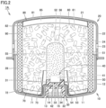
- Fig. 1 is a schematic diagram of a disc-type gas generator according to a first embodiment. A construction of a disc-type gas generator 1A according to the present embodiment will initially be described with reference to Fig. 1 .
- disc-type gas generator 1A has a short substantially cylindrical housing having axial one and the other ends closed, and is constructed to accommodate as internal construction components in an accommodation space provided in the housing, a holding portion 30, an igniter 40, a cup-shaped member 50, an enhancer agent 56, a gas generating agent 61, a lower supporting member 70, an upper supporting member 80, a cushion material 85, a filter 90, and the like.
- a combustion chamber 60 mainly accommodating gas generating agent 61 among the internal construction components described above is located in the accommodation space provided in the housing.
- the housing includes a lower shell 10 and an upper shell 20.
- Each of lower shell 10 and upper shell 20 is made, for example, of a press-formed product formed by press-working a plate-shaped member made of a rolled metal.
- a metal plate composed, for example, of stainless steel, iron steel, an aluminum alloy, a stainless alloy, or the like is made use of as the plate-shaped member made of metal which forms lower shell 10 and upper shell 20, and what is called a high tensile steel plate which is free from such a failure as fracture even at the time of application of tensile stress not lower than 440 MPa and not higher than 780 MPa is suitably made use of.
- Lower shell 10 and upper shell 20 are each formed in a substantially cylindrical shape with bottom, and the housing is constructed by combining and joining the shells such that open surfaces thereof face each other.
- Lower shell 10 has a bottom plate portion 11 and a cylindrical portion 12 and upper shell 20 has a top plate portion 21 and a cylindrical portion 22.
- Cylindrical portion 12 of lower shell 10 has an upper end press-fitted as being inserted in a lower end of cylindrical portion 22 of upper shell 20. Cylindrical portion 12 of lower shell 10 and cylindrical portion 22 of upper shell 20 are joined at a portion of abutment therebetween or in the vicinity thereof so that lower shell 10 and upper shell 20 are fixed. Electron-beam welding, laser welding, friction welding, or the like can suitably be made use of for joining lower shell 10 and upper shell 20 to each other.
- a portion of a circumferential wall portion of the housing close to bottom plate portion 11 is thus formed by cylindrical portion 12 of lower shell 10, and a portion of the circumferential wall portion of the housing close to top plate portion 21 is formed by cylindrical portion 22 of upper shell 20.
- One and the other axial ends of the housing are closed by bottom plate portion 11 of lower shell 10 and top plate portion 21 of upper shell 20, respectively.
- a protruding cylindrical portion 13 protruding toward top plate portion 21 is provided in a central portion of bottom plate portion 11 of lower shell 10, so that a depression portion 14 is formed in the central portion of bottom plate portion 11 of lower shell 10.
- Protruding cylindrical portion 13 is a site to which igniter 40 is fixed with holding portion 30 being interposed, and depression portion 14 is a site serving as a space for providing a female connector portion 34 in holding portion 30.
- Protruding cylindrical portion 13 is formed to be in a substantially cylindrical shape with bottom, and an opening 15 is provided at an axial end portion located on a side of top plate portion 21. Opening 15 is a site through which a pair of terminal pins 42 of igniter 40 passes.
- Igniter 40 serves to produce flames and includes an ignition portion 41 and a pair of terminal pins 42 described above.
- Ignition portion 41 contains an ignition agent producing flames by being ignited to burn at the time of activation and a resistor for igniting this ignition agent.
- the pair of terminal pins 42 is connected to ignition portion 41 for igniting the ignition agent.
- ignition portion 41 includes a squib cup formed like a cup and a plug closing an opening end of the squib cup and holding a pair of terminal pins 42 as being inserted therein.
- the resistor bridge wire
- the ignition agent is loaded in the squib cup so as to surround the resistor or to be in proximity to the resistor.
- a Nichrome wire or the like is generally made use of as a resistor, and ZPP (zirconium potassium perchlorate), ZWPP (zirconium tungsten potassium perchlorate), lead tricinate, or the like is generally made use of as the ignition agent.
- the squib cup and the plug described above are generally made of a metal or plastic.
- a prescribed amount of current flows in the resistor through terminal pin 42.
- Joule heat is generated in the resistor and the ignition agent starts burning. Flame at a high temperature caused by being burnt bursts the squib cup accommodating the ignition agent.
- a time period from flow of a current in the resistor until activation of igniter 40 is generally not longer than 2.0 milliseconds in a case that the Nichrome wire is employed as the resistor.
- Igniter 40 is attached to bottom plate portion 11 in such a manner that terminal pin 42 is introduced from the inside of lower shell 10 to pass through opening 15 provided in protruding cylindrical portion 13.
- holding portion 30 formed from a resin molded portion is provided around protruding cylindrical portion 13 provided in bottom plate portion 11, and igniter 40 is fixed to bottom plate portion 11 as being held by holding portion 30.
- Holding portion 30 is formed through injection molding (more specifically, insert molding) with the use of a mold, and formed by attaching an insulating fluid resin material to bottom plate portion 11 so as to reach a part of an outer surface from a part of an inner surface of bottom plate portion 11 through opening 15 provided in bottom plate portion 11 of lower shell 10 and solidifying the fluid resin material.
- a resin material excellent in heat resistance, durability, corrosion resistance, and the like after curing is suitably selected and made use of.
- a resin material excellent in heat resistance, durability, corrosion resistance, and the like after curing is suitably selected and made use of.
- a thermosetting resin represented by an epoxy resin and the like a thermoplastic resin represented by a polybutylene terephthalate resin, a polyethylene terephthalate resin, a polyamide resin (such as nylon 6 or nylon 66), a polypropylene sulfide resin, a polypropylene oxide resin, and the like can also be made use of.
- these thermoplastic resins are selected as a source material, in order to ensure mechanical strength of holding portion 30 after molding, glass fibers or the like are preferably contained as fillers in these resin materials. In a case where sufficient mechanical strength can be ensured only by a thermoplastic resin, however, a filler as described above does not have to be added.
- Holding portion 30 has an inner cover portion 31 covering a part of an inner surface of bottom plate portion 11 of lower shell 10, an outer cover portion 32 covering a part of an outer surface of bottom plate portion 11 of lower shell 10, and a coupling portion 33 located within opening 15 provided in bottom plate portion 11 of lower shell 10 and continuing to each of inner cover portion 31 and outer cover portion 32.
- Holding portion 30 is secured to bottom plate portion 11 at a surface on a side of bottom plate portion 11, of each of inner cover portion 31, outer cover portion 32, and coupling portion 33. Holding portion 30 is secured at each of a side surface and a lower surface of igniter 40 which is closer to a lower end of ignition portion 41, as well as a surface of a portion of igniter 40 which is closer to an upper end of terminal pin 42.
- opening 15 is completely buried by terminal pin 42 and holding portion 30, so that hermeticity of the space in the housing is ensured by sealability ensured in that portion.
- female connector portion 34 is formed in a portion of outer cover portion 32 of holding portion 30, which faces the outside.
- This female connector portion 34 is a site for receiving a male connector (not shown) of a harness for connecting igniter 40 and a control unit (not shown) to each other, and it is located in depression portion 14 provided in bottom plate portion 11 of lower shell 10.
- Injection molding described above may be carried out with the use of lower shell 10 obtained by providing an adhesive layer in advance at a prescribed position on a surface of bottom plate portion 11 in a portion to be covered with holding portion 30.
- the adhesive layer can be formed by applying an adhesive in advance to a prescribed position of bottom plate portion 11 and curing the adhesive.
- an adhesive containing as a source material, a resin material excellent in heat resistance, durability, corrosion resistance, and the like after curing is suitably made use of, and for example, an adhesive containing a cyanoacrylate-based resin or a silicone-based resin as a source material is particularly suitably made use of.
- the cured adhesive layer is located between bottom plate portion 11 and holding portion 30, so that holding portion 30 formed from a resin molded portion can more firmly be secured to bottom plate portion 11. Therefore, by providing the adhesive layer annularly along a circumferential direction so as to surround opening 15 provided in bottom plate portion 11, higher sealability can be ensured in that portion.
- igniter 40 can be fixed to lower shell 10 by injection molding holding portion 30 formed from the resin molded portion
- other alternative means can also be used for fixing igniter 40 to lower shell 10.
- Cup-shaped member 50 is assembled to bottom plate portion 11 so as to cover protruding cylindrical portion 13, holding portion 30, and igniter 40.
- Cup-shaped member 50 has a substantially cylindrical shape with bottom having an open end portion on the side of bottom plate portion 11, and contains an enhancer chamber 55 accommodating enhancer agent 56.
- Cup-shaped member 50 is arranged to protrude into combustion chamber 60 accommodating gas generating agent 61, such that enhancer chamber 55 provided therein faces ignition portion 41 of igniter 40.
- Cup-shaped member 50 has a cylindrical sidewall portion 51 which defines enhancer chamber 55 described above, a top wall portion 52 which defines enhancer chamber 55 and closes an axial end portion of sidewall portion 51 located on the side of top plate portion 21, and an extension portion 53 provided to extend radially outward from a portion of sidewall portion 51 on a side of an open end.
- Extension portion 53 is formed to extend along an inner surface of bottom plate portion 11 of lower shell 10.
- extension portion 53 is in a shape curved along a shape of an inner bottom surface of bottom plate portion 11 in a portion where protruding cylindrical portion 13 is provided and in the vicinity thereof and includes a tip end portion 54 extending like a flange in a radially outer portion thereof.
- Tip end portion 54 in extension portion 53 is arranged between bottom plate portion 11 and lower supporting member 70 along the axial direction of the housing and sandwiched between bottom plate portion 11 and lower supporting member 70 along the axial direction of the housing. Since lower supporting member 70 is pressed toward bottom plate portion 11 by gas generating agent 61, cushion material 85, upper supporting member 80, and top plate portion 21 arranged above, cup-shaped member 50 is in such a state that tip end portion 54 of extension portion 53 is pressed toward bottom plate portion 11 by lower supporting member 70 and fixed to bottom plate portion 11. Thus, cup-shaped member 50 is prevented from falling from bottom plate portion 11 without using swaging or press-fitting for fixing cup-shaped member 50.
- Cup-shaped member 50 has an opening in neither of sidewall portion 51 and top wall portion 52 and surrounds enhancer chamber 55 provided therein. This cup-shaped member 50 bursts or melts with increase in pressure in enhancer chamber 55 or conduction of heat generated therein when enhancer agent 56 is ignited as a result of activation of igniter 40, and mechanical strength thereof is relatively low.
- a member made of metal such as aluminum or an aluminum alloy or a member made of a resin such as a thermosetting resin represented by an epoxy resin and the like and a thermoplastic resin represented by a polybutylene terephthalate resin, a polyethylene terephthalate resin, a polyamide resin (such as nylon 6 or nylon 66), a polypropylene sulfide resin, a polypropylene oxide resin, and the like is suitably made use of for cup-shaped member 50.
- a resin such as a thermosetting resin represented by an epoxy resin and the like and a thermoplastic resin represented by a polybutylene terephthalate resin, a polyethylene terephthalate resin, a polyamide resin (such as nylon 6 or nylon 66), a polypropylene sulfide resin, a polypropylene oxide resin, and the like is suitably made use of for cup-shaped member 50.
- a method of fixing cup-shaped member 50 is not limited to a fixing method using lower supporting member 70 described above, and other fixing methods may be made use of.
- Enhancer agent 56 charged into enhancer chamber 55 generates thermal particles as it is ignited to burn by flames produced as a result of activation of igniter 40.
- Enhancer agent 56 should be able to reliably start burning gas generating agent 61, and generally, a composition composed of metal powders/oxidizing agent represented by B/KNO 3 , B/NaNO 3 , or Sr(NO 3 ) 2 , a composition composed of titanium hydride/potassium perchlorate, or a composition composed of B/5-aminotetrazole/potassium nitrate/molybdenum trioxide is employed.
- enhancer agent 56 a powdery enhancer agent, an enhancer agent formed in a prescribed shape by a binder, or the like is made use of.
- a shape of enhancer agent 56 formed by a binder includes, for example, various shapes such as a granule, a column, a sheet, a sphere, a cylinder with a single hole, a cylinder with multiple holes, a tablet, and the like.
- combustion chamber 60 accommodating gas generating agent 61 is located.
- cup-shaped member 50 is arranged to protrude into combustion chamber 60 formed in the housing, and a space provided in a portion of this cup-shaped member 50 facing the outer surface of sidewall portion 51 and a space provided in a portion thereof facing an outer surface of top wall portion 52 are provided as combustion chamber 60.
- filter 90 is arranged along an inner circumference of the housing. Filter 90 is held by the housing in an axially compressed state by being sandwiched between top plate portion 21 and bottom plate portion 11 of the housing. Filter 90 has a hollow cylindrical shape and is arranged such that a central axis thereof substantially matches with the axial direction of the housing.
- Gas generating agent 61 is an agent which is ignited by thermal particles generated as a result of activation of igniter 40 and produces gas as it burns.
- a non-azide-based gas generating agent is preferably employed as gas generating agent 61, and gas generating agent 61 is formed as a molding generally containing a fuel, an oxidizing agent, and an additive.
- a triazole derivative, a tetrazole derivative, a guanidine derivative, an azodicarbonamide derivative, a hydrazine derivative, or the like, or combination thereof is made use of.
- nitroguanidine, guanidine nitrate, cyanoguanidine, 5-aminotetrazole, and the like are suitably made use of.
- oxidizing agent for example, basic nitrate such as basic copper nitrate, perchlorate such as ammonium perchlorate or potassium perchlorate, nitrate containing cations selected from an alkali metal, an alkali earth metal, a transition metal, and ammonia, or the like is made use of.
- basic nitrate such as basic copper nitrate
- perchlorate such as ammonium perchlorate or potassium perchlorate
- nitrate for example, sodium nitrate, potassium nitrate, or the like is suitably made use of.
- a binder for example, an organic binder such as polyvinyl alcohol, metal salt of carboxymethyl cellulose, and stearate, or an inorganic binder such as synthetic hydrotalcite and Japanese acid clay can suitably be made use of.
- polysaccharide derivatives such as hydroxyethyl cellulose, hydroxypropyl methylcellulose, cellulose acetate, cellulose propionate, cellulose acetate butyrate, nitrocellulose, microcrystalline cellulose, guar gum, polyvinyl pyrrolidone, polyacrylamide, and starch and inorganic binders such as molybdenum disulfide, talc, bentonite, diatomite, kaolin, and alumina can also suitably be made use of.
- silicon nitride, silica, Japanese acid clay, or the like can suitably be made use of.
- a metal oxide, ferrosilicon, activated carbon, graphite, or the like can suitably be made use of.
- a shape of a molding of gas generating agent 61 includes various shapes such as a particulate shape including a granule, a pellet, and a column, and a disc shape.
- a molding with holes having through holes in the molding is also made use of.
- These shapes are preferably selected as appropriate depending on specifications of an air bag apparatus in which disc-type gas generator 1A is incorporated, and for example, a shape optimal for the specifications is preferably selected by selecting a shape allowing change over time of a rate of generation of gas during burning of gas generating agent 61.
- a size of a molding or an amount thereof for filling is preferably selected as appropriate, in consideration of a linear burning velocity, a pressure exponent, or the like of gas generating agent 61.
- Filter 90 is made of a wound body or a braided body of metal wire rods.
- a filter obtained by winding a metal wire rod of stainless steel or iron steel, a filter formed by press-working a mesh material into which metal wire rods are knitted to thereby pack the same, or the like can be made use of.
- the mesh material specifically, a wire gauze of stocking stitch, a plain-woven wire gauze, an aggregate of crimped metal wire rods, or the like can be made use of.
- Filter 90 functions as cooling means for cooling gas by removing heat at a high temperature of gas when gas produced in combustion chamber 60 passes through this filter 90 and also functions as removal means for removing residues (slug) or the like contained in gas. Therefore, in order to sufficiently cool gas and to prevent emission of residues to the outside, gas generated in combustion chamber 60 should reliably pass through filter 90.
- filter 90 In disc-type gas generator 1A according to the present embodiment, a filter relatively largely elastically deformable along the axial direction is employed as filter 90. Therefore, filter 90 has high resilience which is ability to greatly expand along the axial direction when the filter is unloaded from the state compressed along the axial direction. By employing such filter 90, gas generated in the combustion chamber can reliably pass through filter 90 and efficiency in use of filter 90 can be enhanced, which will be described later.
- Filter 90 is arranged to be distant from cylindrical portions 12 and 22 so as to provide a gap 28 of a prescribed size between cylindrical portion 12 of lower shell 10 and cylindrical portion 22 of upper shell 20 which form the circumferential wall portion of the housing. According to such a construction, gas can more smoothly flow in the inside of filter 90 and efficiency in use of filter 90 can be higher than in an example where filter 90 is arranged as being in contact with cylindrical portions 12 and 22.
- a plurality of gas discharge openings 23 are provided in cylindrical portion 22 of upper shell 20 in a portion facing filter 90.
- the plurality of gas discharge openings 23 serve for guiding gas which has passed through filter 90 to the outside of the housing.
- sealing tape 24 made of a metal as a sealing member is attached to close the plurality of gas discharge openings 23.
- An aluminum foil or the like having a tacky member applied to its one surface is suitably made use of as this sealing tape 24 and hermeticity of combustion chamber 60 is ensured by sealing tape 24.
- Lower supporting member 70 is a member that positions and holds filter 90 by coming in contact with the inner circumferential surface of filter 90 located on the side of bottom plate portion 11.
- Lower supporting member 70 has an annular shape and is arranged as substantially being applied to filter 90 and bottom plate portion 11 so as to cover a boundary portion between filter 90 and bottom plate portion 11. Thus, lower supporting member 70 is located between bottom plate portion 11 and gas generating agent 61 in the vicinity of the end portion of combustion chamber 60.
- Lower supporting member 70 includes a base portion 71 in a shape of an annular plate applied to bottom plate portion 11 along the inner bottom surface of bottom plate portion 11, an abutment portion 72 which abuts on an inner circumferential surface of filter 90 close to bottom plate portion 11, and a cylindrical partition wall portion 73 erected from base portion 71 toward top plate portion 21.
- Abutment portion 72 is provided to extend from an outer edge of base portion 71 and partition wall portion 73 is provided to extend from an inner edge of base portion 71.
- Lower supporting member 70 is made from a member which does not burst or melt even by combustion of enhancer agent 56 with activation of igniter 40.
- Lower supporting member 70 is formed, for example, by press-working a plate-shaped member made of metal, and suitably made of a member formed from a steel plate of common steel, special steel, or the like (such as a cold rolled steel plate or a stainless steel plate).
- Tip end portion 54 of extension portion 53 of cup-shaped member 50 described above is arranged between bottom plate portion 11 and base portion 71 of lower supporting member 70 along the axial direction of the housing.
- tip end portion 54 is held as being sandwiched between bottom plate portion 11 and base portion 71 along the axial direction of the housing.
- cup-shaped member 50 is in such a state that tip end portion 54 of extension portion 53 is pressed toward bottom plate portion 11 by base portion 71 of lower supporting member 70 and fixed to bottom plate portion 11.
- Upper supporting member 80 is arranged at the end portion of combustion chamber 60 located on the side of top plate portion 21.
- Upper supporting member 80 is a member that positions and holds filter 90 by coming in contact with the inner circumferential surface of filter 90 located on the side of top plate portion 21.
- Upper supporting member 80 is substantially in a shape of a disc and is arranged as being applied to filter 90 and top plate portion 21 so as to cover the boundary portion between filter 90 and top plate portion 21. Thus, upper supporting member 80 is located between top plate portion 21 and gas generating agent 61 in the vicinity of the end portion of combustion chamber 60.
- Upper supporting member 80 has a base portion 81 abutting on top plate portion 21 and an abutment portion 82 erected from a peripheral edge of base portion 81. Abutment portion 82 abuts on the inner circumferential surface of an axial end portion of filter 90 located on the side of top plate portion 21.
- Upper supporting member 80 is made from a member which does not burst or melt even by combustion of enhancer agent 56 with activation of igniter 40.
- upper supporting member 80 is formed, for example, by press-working a plate-shaped member made of metal, and suitably made of a member formed from a steel plate of common steel, special steel, or the like (such as a cold rolled steel plate or a stainless steel plate).
- annular cushion material 85 is arranged to be in contact with gas generating agent 61 accommodated in combustion chamber 60. Cushion material 85 is thus located between top plate portion 21 and gas generating agent 61 in a portion of combustion chamber 60 on the side of top plate portion 21 and presses gas generating agent 61 toward bottom plate portion 11.
- Cushion material 85 is provided for the purpose of preventing gas generating agent 61 made of a molding from being crushed by vibration or the like, and made of a member suitably formed of a molding of ceramic fibers, rock wool, or a foamed resin (such as foamed silicone, foamed polypropylene, or foamed polyethylene), or rubber represented by chloroprene and EPDM.
- a foamed resin such as foamed silicone, foamed polypropylene, or foamed polyethylene
- Fig. 2 is a schematic diagram showing a state at the time of activation, of the disc-type gas generator shown in Fig. 1 .
- An operation of disc-type gas generator 1A in the present embodiment described above will now be described with reference to Fig. 2 .
- a collision sensing means separately provided in the vehicle senses collision, and based thereon, igniter 40 is activated in response to power feed through a control unit separately provided in the vehicle.
- Enhancer agent 56 accommodated in enhancer chamber 55 is ignited to burn by flames produced as a result of activation of igniter 40, to thereby generate a large amount of thermal particles. Burning of this enhancer agent 56 bursts or melts cup-shaped member 50 and the thermal particles described above flow into combustion chamber 60.
- the thermal particles which have flowed in ignite and burn gas generating agent 61 accommodated in combustion chamber 60 and a large amount of gas is produced.
- Gas produced in combustion chamber 60 passes through filter 90. At that time, heat is removed from gas through filter 90 and gas is cooled, slug contained in gas is removed by filter 90, and gas flows into gap 28.
- sealing tape 24 which has closed gas discharge opening 23 provided in upper shell 20 is cleaved and gas is discharged to the outside of the housing through gas discharge opening 23. Discharged gas is introduced in the air bag provided adjacent to disc-type gas generator 1A and it expands and develops the air bag.
- filter 90 In disc-type gas generator 1A according to the present embodiment, as described above, a highly resilient filter is employed as filter 90. Therefore, even when axial compressive force applied to filter 90 becomes weaker due to deformation of the housing to expand axially outward, filter 90 expands along the axial direction based on resilience thereof, and accordingly, the state of pressure contact thereof with top plate portion 21 and bottom plate portion 11 is maintained. Therefore, since filter 90 expands to follow axial deformation of the housing even at the time of activation of disc-type gas generator 1A, no gap is created between the housing and filter 90 and gas generated in combustion chamber 60 reliably passes through filter 90.
- a filter that has an axial length expanded by at least 1.0 mm as compared with the state in which the filter is sandwiched between top plate portion 21 and bottom plate portion 11, when sandwiching between top plate portion 21 and bottom plate portion 11 is removed to apply no load, is employed as filter 90.
- the reason why such a filter 90 is employed is based on results in first and second verification tests which will be described later.
- filter 90 as above also achieves such an effect that compressive load necessary for sandwiching the filter between top plate portion 21 and bottom plate portion 11 can be low in assembly of filter 90 to the housing. Therefore, disc-type gas generator 1A according to the present embodiment can achieve also an effect of improvement in ease of assembly in manufacturing.
- lower supporting member 70 and upper supporting member 80 are provided in combustion chamber 60.
- Lower supporting member 70 and upper supporting member 80 are provided to position and hold filter 90.
- Lower supporting member 70 is provided to hold cup-shaped member 50 by sandwiching tip end portion 54 of cup-shaped member 50 between lower supporting member 70 and bottom plate portion 11.
- the lower supporting member and the upper supporting member perform not only the function described above but also a function as the leakage prevention member that prevents, by covering a gap that may be created between the housing and the filter at the time of activation, gas from flowing out through the gap.
- lower supporting member 70 and upper supporting member 80 do not perform such a function.
- disc-type gas generator 1A is constructed such that highly resilient filter 90 described above prevents creation of the gap described above without depending on lower supporting member 70 and upper supporting member 80 and gas generated in combustion chamber 60 thus reliably passes through filter 90.
- the axial lengths thereof should considerably be long such that respective abutment portions 72 and 82 of lower supporting member 70 and upper supporting member 80 reliably abut on the inner circumferential surface of filter 90.
- the lower supporting member and the upper supporting member do not perform the function as the leakage prevention member, and hence the axial lengths of abutment portions 72 and 82 can sufficiently be short.
- an area of portions of the inner circumferential surface of filter 90 covered with abutment portions 72 and 82 can be small. Consequently, gas generated in combustion chamber 60 passes through a larger portion of filter 90 and consequently efficiency in use of the filter is significantly enhanced. Decrease in axial lengths of respective abutment portions 72 and 82 of lower supporting member 70 and upper supporting member 80 can also lead to such a side benefit as reduction in material cost and reduction in weight of disc-type gas generator 1A.
- disc-type gas generator 1A As described above, with disc-type gas generator 1A according to the present embodiment, a disc-type gas generator in which gas generated in the combustion chamber can reliably pass through the filter and efficiency in use of the filter is hence enhanced can be obtained.
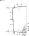
- Fig. 3 is a schematic diagram for illustrating the first verification test. For the sake of facilitated understanding, Fig. 3 shows only lower shell 10 and upper shell 20 that form the housing, holding portion 30, and igniter 40.
- a disc-type gas generator in which an amount of gas generated at the time of activation was 1.3 mol and a disc-type gas generator in which an amount of gas generated at the time of activation was 3.0 mol were prepared.
- Each of the disc-type gas generators was activated, and thereafter an amount of axial deformation of the housing in a portion of abutment on the filter (a portion shown with a reference FP in the figure) was measured.
- the housing of the disc-type gas generator in which the amount of gas generated at the time of activation was 1.3 mol had an outer diameter of 58 mm, an axial length of 38 mm, and a thickness in bottom plate portion 11 and top plate portion 21 of 1.5 mm.
- the housing of the disc-type gas generator in which an amount of gas generated at the time of activation was 3.0 mol had an outer diameter of 70 mm, an axial length of 60 mm, and a thickness in bottom plate portion 11 and top plate portion 21 of 1.5 mm.
- bottom plate portion 11 of lower shell 10 and top plate portion 21 of upper shell 20 were displaced from positions before activation shown with dashed lines in the figure to positions shown with solid lines in the figure.
- the amount of axial deformation of the housing in portions FP of abutment on the filter described above corresponds to the sum of an amount of displacement Gal of bottom plate portion 11 and an amount of displacement Ga2 of top plate portion 21.
- the amount of axial deformation of the housing in portions FP of abutment on the filter was 0.8 mm in the disc-type gas generator in which the amount of gas generated at the time of activation was 1.3 mol and 1.0 mm in the disc-type gas generator in which the amount of gas generated at the time of activation was 3.0 mol.
- filter 90 the filter that had the axial length expanded by at least 1.0 mm as compared with the state in which the filter was sandwiched between top plate portion 21 and bottom plate portion 11, when sandwiching between top plate portion 21 and bottom plate portion 11 was removed to apply no load, filter 90 expanded to follow axial deformation of the housing even at the time of activation of the gas generator and creation of the gap between the housing and filter 90 could effectively be suppressed.
- Fig. 4 is a schematic diagram showing a test procedure in the second verification test.
- Figs. 5 to 8 show graphs or tables of results in the second verification test.
- Example 1 a highly resilient filter (that is, a filter high in resilience in the axial direction) expected to be assembled to the disc-type gas generator in which the amount of gas generated at the time of activation was 1.3 mol was prepared as Example 1, and a highly resilient filter expected to be assembled to the disc-type gas generator in which the amount of gas generated at the time of activation was 3.0 mol was prepared as Example 2.
- a filter low in resilience that is, a filter poor in resilience in the axial direction
- a filter low in resilience expected to be assembled to the disc-type gas generator in which the amount of gas generated at the time of activation was 3.0 mol was prepared as Comparative Example 1
- Comparative Example 2 a filter low in resilience expected to be assembled to the disc-type gas generator in which the amount of gas generated at the time of activation was 3.0 mol
- the filters according to Example 1 and Comparative Example 1 each had an outer diameter of 50 mm, an axial length of 37 mm, and a thickness of 3.5 mm.
- the filters according to Example 2 and Comparative Example 2 each had an outer diameter of 60 mm, an axial length of 60 mm, and a thickness of 4.5 mm.
- filters 90 according to Examples 1 and 2 and Comparative Examples 1 and 2 were compressed by a prescribed amount along the axial direction, and thereafter compression applied to filters 90 was removed. At that time, relation between a compressive load F applied to filter 90 and an amount of compression Ha along the axial direction of the filter and relation between amount of compression Ha along the axial direction of filter 90 and an amount of resilience Hc along the axial direction of filter 90 were measured.
- a compression tester 100 was used for filter 90 to compress filter 90 in a direction shown with an arrow AR1 in the figure as shown in Fig. 4 (B) , and relation between amount of compression Ha along the axial direction of the filter and compressive load F applied to filter 90 at that time was measured. Thereafter, from the state in which compressive load F was applied to filter 90 with the use of compression tester 100 as shown in Fig. 4 (B) , compression tester 100 was moved backward in a direction shown with an arrow AR2 in the figure as shown in Fig. 4 (C) to remove compression onto filter 90 for unloading. Filter 90 was thus allowed to expand (that is, to recover the original state) along the axial direction and relation between amount of compression Ha along the axial direction of filter 90 and amount of resilience Hc along the axial direction of filter 90 at that time was measured.
- Fig. 5 shows a graph of relation between amount of compression Ha and compressive load F of the filter according to Example 1 and relation between amount of compression Ha and compressive load F of the filter according to Comparative Example 1.
- Fig. 6 shows a graph of relation between amount of compression Ha and compressive load F of the filter according to Example 2 and relation between amount of compression Ha and compressive load F of the filter according to Comparative Example 2.
- the filter according to Example 2 and the filter according to Comparative Example 2 were compared with each other. Throughout a range from a point where amount of compression Ha exceeded 0.0 mm to at least 3.0 mm, at equivalent amount of compression Ha, compressive load F of the filter according to Example 2 was lower than compressive load F of the filter according to Comparative Example 2. This tendency was most noticeable in a range of amounts of compression Ha from approximately 0.5 mm to approximately 3.0 mm, and compressive load F of the filter according to Example 2 was lower by approximately 0.4 kN to approximately 0.6 kN than compressive load F of the filter according to Comparative Example 2.
- disc-type gas generator 1A according to the first embodiment described above achieved an effect of improvement in ease of assembly in assembly of the filter.
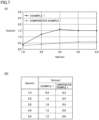
- Fig. 7 (A) shows a graph of relation between amount of compression Ha and amount of resilience Hc of the filter according to Example 1 and relation between amount of compression Ha and amount of resilience Hc of the filter according to Comparative Example 1, and Fig. 7 (B) shows a table thereof.
- amount of compression Ha was 1.0 mm
- amount of resilience Hc of the filter according to Example 1 was 0.4 mm and amount of resilience Hc of the filter according to Comparative Example 1 was 0.3 mm.
- amounts of compression Ha were 2.0 mm, 3.0 mm, 4.0 mm, and 5.0 mm
- amount of resilience Hc of the filter according to Example 1 was larger than 1.0 mm in each case
- amount of resilience Hc of the filter according to Comparative Example 1 was smaller than 1.0 mm in each case.
- amount of resilience Hc was largest when amount of compression Ha was 3.0 mm
- amount of resilience Hc at that time was 1.6 mm.
- amount of resilience Hc was 1.2 mm when amount of compression Ha was 2.0 mm.
- Fig. 8 (A) shows a graph of relation between amount of compression Ha and amount of resilience Hc of the filter according to Example 2 and relation between amount of compression Ha and amount of resilience Hc of the filter according to Comparative Example 2, and Fig. 8 (B) shows a table thereof.
- amount of compression Ha was 1.0 mm
- amount of resilience Hc of the filter according to Example 2 was 0.7 mm
- amount of resilience Hc of the filter according to Comparative Example 2 was 0.6 mm.
- amount of resilience Hc of the filter according to Example 2 was larger than 1.0 mm in each case
- amount of resilience Hc of the filter according to Comparative Example 2 was smaller than 1.0 mm in each case.
- amount of resilience Hc was largest when amount of compression Ha was 5.0 mm in the range of measurement, and amount of resilience Hc at that time was 2.6 mm.
- amount of resilience Hc was 2.0 mm when amount of compression Ha was 3.0 mm.
- the disc-type gas generator in which the amount of gas generated at the time of activation was 1.3 mol and the disc-type gas generator in which the amount of gas generated at the time of activation was 3.0 mol were prepared and verification thereof was conducted. It is estimated that the effect described in the first embodiment above is achieved also by employing a highly resilient filter (more specifically, a filter that has an axial length expanded by at least 1.0 mm when sandwiching between the top plate portion and the bottom plate portion is removed to apply no load) as the filter to be assembled to the disc-type gas generator in which the amount of gas generated at the time of activation is 1.0 mol encompassed in the standard disc-type gas generator described above.
- a highly resilient filter more specifically, a filter that has an axial length expanded by at least 1.0 mm when sandwiching between the top plate portion and the bottom plate portion is removed to apply no load
- the amount of axial deformation of the housing in the portion of abutment on the filter at the time of activation of the disc-type gas generator in which the amount of generated gas was 1.3 mol was 0.8 mm.
- the amount of axial deformation of the housing can be suppressed to 0.8 mm or less. Therefore, it is considered that, with the use of the highly resilient filter described above, the state of pressure contact of the filter with the top plate portion and the bottom plate portion is maintained owing to resilience thereof even at the time of activation of the disc-type gas generator.
- Fig. 9 (A) is a schematic diagram showing operations assumed when the disc-type gas generator in which the filter according to Example 1 or 2 is assembled is activated
- Fig. 9 (B) is a schematic diagram showing operations assumed when the disc-type gas generator in which the filter according to Comparative Example 1 or 2 is assembled is activated.
- a disc-type gas generator 1A' in which the highly resilient filter (that is, the filter according to Example 1 or 2) is assembled, filter 90 expands to follow axial deformation of the housing even at the time of activation thereof. Therefore, no gap is created between top plate portion 21 and filter 90 and between bottom plate portion 11 and filter 90. Therefore, gas generated in combustion chamber 60 reliably passes through filter 90.
- the highly resilient filter that is, the filter according to Example 1 or 2
- a gap Gb is created between both or one of top plate portion 21 and bottom plate portion 11 and filter 90 (the figure assumes and illustrates an example where a gap is created between top plate portion 21 and filter 90).
- gap Gb was 0.4 mm in the disc-type gas generator in which the amount of gas generated at the time of activation was 1.3 mol and 0.3 mm in the disc-type gas generator in which the amount of gas generated at the time of activation was 3.0 mol. Therefore, when no measures are taken in disc-type gas generator 1X, some of gas generated in the combustion chamber flows out through gap Gb into a gap portion 28 without passing through filter 90.
- lower supporting member 70 and upper supporting member 80 should function as the leakage prevention members as described above to prevent leakage of gas through gap Gb.
- the axial lengths of respective abutment portions 72 and 82 of lower supporting member 70 and upper supporting member 80 should considerably be long.
- lower supporting member 70 and upper supporting member 80 do not have to perform such a function as the leakage prevention member, and hence the axial lengths of abutment portions 72 and 82 can sufficiently be short.
- an area of portions of the inner circumferential surface of filter 90 covered with abutment portions 72 and 82 can be small and hence gas generated in combustion chamber 60 passes through a larger portion of filter 90. Consequently, efficiency in use of filter 90 can significantly be enhanced and reduction in material cost or weight can be achieved.
- Fig. 10 is a schematic diagram of a disc-type gas generator according to a second embodiment.
- a disc-type gas generator 1B in the present embodiment will be described below with reference to Fig. 10 .
- disc-type gas generator 1B in the present embodiment is different from disc-type gas generator 1A in the first embodiment described above only in construction thereof that upper supporting member 80 is not provided in combustion chamber 60.
- lower supporting member 70 and upper supporting member 80 provided in combustion chamber 60 position and hold filter 90
- only lower supporting member 70 provided in combustion chamber 60 positions and holds filter 90
- the disc-type gas generator in which both of a lower support portion and the upper supporting member are provided in the combustion chamber is illustrated and described
- the disc-type gas generator in which the lower supporting member is provided in the combustion chamber but the upper supporting member is not provided in the combustion chamber is illustrated and described.
- the present invention may be applied to a disc-type gas generator in which the upper supporting member is provided in the combustion chamber but the lower supporting member is not provided in the combustion chamber or to a disc-type gas generator in which neither of an upper support portion and the lower supporting member is provided in the combustion chamber.
- 1A, 1A', 1B, 1X disc-type gas generator 10 lower shell; 11 bottom plate portion; 12 cylindrical portion; 13 protruding cylindrical portion; 14 depression portion; 15 opening; 20 upper shell; 21 top plate portion; 22 cylindrical portion; 23 gas discharge opening; 24 sealing tape; 28 gap; 30 holding portion; 31 inner cover portion; 32 outer cover portion; 33 coupling portion; 34 female connector portion; 40 igniter; 41 ignition portion; 42 terminal pin; 50 cup-shaped member; 51 sidewall portion; 52 top wall portion; 53 extension portion; 54 tip end portion; 55 enhancer chamber; 56 enhancer agent; 60 combustion chamber; 61 gas generating agent; 70 lower supporting member; 71 base portion; 72 abutment portion; 73 partition wall portion; 80 upper supporting member; 81 base portion; 82 abutment portion; 85 cushion material; 90 filter; 100 compression tester
Landscapes
- Physics & Mathematics (AREA)
- Fluid Mechanics (AREA)
- Engineering & Computer Science (AREA)
- Mechanical Engineering (AREA)
- Air Bags (AREA)
Applications Claiming Priority (2)
| Application Number | Priority Date | Filing Date | Title |
|---|---|---|---|
| JP2021081849A JP2022175461A (ja) | 2021-05-13 | 2021-05-13 | ガス発生器 |
| PCT/JP2022/019645 WO2022239727A1 (ja) | 2021-05-13 | 2022-05-09 | ガス発生器 |
Publications (1)
| Publication Number | Publication Date |
|---|---|
| EP4339041A1 true EP4339041A1 (en) | 2024-03-20 |
Family
ID=84029637
Family Applications (1)
| Application Number | Title | Priority Date | Filing Date |
|---|---|---|---|
| EP22807428.2A Withdrawn EP4339041A1 (en) | 2021-05-13 | 2022-05-09 | Gas generator |
Country Status (4)
| Country | Link |
|---|---|
| US (1) | US20240239297A1 (enExample) |
| EP (1) | EP4339041A1 (enExample) |
| JP (1) | JP2022175461A (enExample) |
| WO (1) | WO2022239727A1 (enExample) |
Family Cites Families (16)
| Publication number | Priority date | Publication date | Assignee | Title |
|---|---|---|---|---|
| US5221107A (en) * | 1990-12-18 | 1993-06-22 | Trw Inc. | Prefilter assembly |
| WO1994025315A1 (en) * | 1993-04-29 | 1994-11-10 | Automotive Systems Laboratory, Inc. | Inflator having a rupturable igniter tube |
| US5551724A (en) * | 1993-09-14 | 1996-09-03 | Morton International, Inc. | Treatment of inflatable restraint system inflator particulate-containing gas with expanded metal |
| US5556130A (en) * | 1994-10-05 | 1996-09-17 | Morton International, Inc. | Single side wall air bag inflator |
| US5938236A (en) * | 1996-07-17 | 1999-08-17 | Nippon Kayaku Kabushiki-Kaisha | Gas generator for an air bag |
| WO2000068043A1 (en) * | 1999-05-11 | 2000-11-16 | Automotive Systems Laboratory, Inc. | Dual chamber inflator |
| JP4532124B2 (ja) * | 2004-01-07 | 2010-08-25 | ダイセル化学工業株式会社 | エアバッグガス発生器用フィルタ |
| EP1669258A1 (de) * | 2004-12-08 | 2006-06-14 | Delphi Technologies, Inc. | Gasgenerator |
| JP2007160954A (ja) * | 2005-12-09 | 2007-06-28 | Daicel Chem Ind Ltd | 車両の乗員拘束装置用ガス発生器 |
| US7503581B2 (en) * | 2006-03-22 | 2009-03-17 | Daicel Chemical Industries, Ltd. | Gas generator for occupant restraining device for vehicle |
| JP4402705B2 (ja) * | 2007-05-21 | 2010-01-20 | 富士フィルター工業株式会社 | エアバッグインフレーター用フィルター、およびその製造方法 |
| JP6023663B2 (ja) | 2013-06-07 | 2016-11-09 | 日本化薬株式会社 | ガス発生器用フィルタおよびガス発生器 |
| CN108698556B (zh) * | 2016-02-23 | 2021-04-02 | 日本化药株式会社 | 气体发生器 |
| JP2017149228A (ja) * | 2016-02-23 | 2017-08-31 | 日本化薬株式会社 | ガス発生器 |
| JP2019069677A (ja) * | 2017-10-06 | 2019-05-09 | 株式会社ダイセル | ガス発生器 |
| JP7089910B2 (ja) * | 2018-03-12 | 2022-06-23 | 株式会社ダイセル | 火工装置用の筒状フィルタ、前記筒状フィルタの製造方法、前記筒状フィルタを使用した火工装置 |
-
2021
- 2021-05-13 JP JP2021081849A patent/JP2022175461A/ja not_active Withdrawn
-
2022
- 2022-05-09 US US18/558,586 patent/US20240239297A1/en not_active Abandoned
- 2022-05-09 WO PCT/JP2022/019645 patent/WO2022239727A1/ja not_active Ceased
- 2022-05-09 EP EP22807428.2A patent/EP4339041A1/en not_active Withdrawn
Also Published As
| Publication number | Publication date |
|---|---|
| US20240239297A1 (en) | 2024-07-18 |
| WO2022239727A1 (ja) | 2022-11-17 |
| JP2022175461A (ja) | 2022-11-25 |
Similar Documents
| Publication | Publication Date | Title |
|---|---|---|
| US10953842B2 (en) | Gas generator | |
| US9902364B2 (en) | Gas generator | |
| US11110885B2 (en) | Gas generator | |
| US10870409B2 (en) | Gas generator | |
| US10759377B2 (en) | Gas generator | |
| US11052865B2 (en) | Gas generator | |
| US11247164B2 (en) | Filter for gas generator and gas generator | |
| EP4339041A1 (en) | Gas generator | |
| JP2015157618A (ja) | ガス発生器 | |
| JP6579991B2 (ja) | ガス発生器 | |
| US12365304B2 (en) | Igniter and gas generator | |
| JP2016107702A (ja) | ガス発生器 | |
| CN117320930A (zh) | 气体发生器 | |
| EP4474035A1 (en) | Winding filter | |
| JP2025151222A (ja) | ガス発生器 | |
| WO2025243749A1 (ja) | ガス発生器 | |
| JP2024042621A (ja) | ガス発生器をモジュールに取り付ける際の位置合わせ機構 | |
| JP2020152223A (ja) | ガス発生器 | |
| JP2020131910A (ja) | ガス発生器 | |
| JP2021024459A (ja) | ガス発生器 |
Legal Events
| Date | Code | Title | Description |
|---|---|---|---|
| STAA | Information on the status of an ep patent application or granted ep patent |
Free format text: STATUS: THE INTERNATIONAL PUBLICATION HAS BEEN MADE |
|
| PUAI | Public reference made under article 153(3) epc to a published international application that has entered the european phase |
Free format text: ORIGINAL CODE: 0009012 |
|
| STAA | Information on the status of an ep patent application or granted ep patent |
Free format text: STATUS: REQUEST FOR EXAMINATION WAS MADE |
|
| 17P | Request for examination filed |
Effective date: 20231102 |
|
| AK | Designated contracting states |
Kind code of ref document: A1 Designated state(s): AL AT BE BG CH CY CZ DE DK EE ES FI FR GB GR HR HU IE IS IT LI LT LU LV MC MK MT NL NO PL PT RO RS SE SI SK SM TR |
|
| DAV | Request for validation of the european patent (deleted) | ||
| DAX | Request for extension of the european patent (deleted) | ||
| STAA | Information on the status of an ep patent application or granted ep patent |
Free format text: STATUS: THE APPLICATION HAS BEEN WITHDRAWN |
|
| 18W | Application withdrawn |
Effective date: 20241008 |