EP4339010A2 - Vorrichtung zur übertragung elektrischer energie mit einem zentriersystem - Google Patents
Vorrichtung zur übertragung elektrischer energie mit einem zentriersystem Download PDFInfo
- Publication number
- EP4339010A2 EP4339010A2 EP23181030.0A EP23181030A EP4339010A2 EP 4339010 A2 EP4339010 A2 EP 4339010A2 EP 23181030 A EP23181030 A EP 23181030A EP 4339010 A2 EP4339010 A2 EP 4339010A2
- Authority
- EP
- European Patent Office
- Prior art keywords
- electrical energy
- energy transfer
- lateral surface
- transfer device
- housing
- Prior art date
- Legal status (The legal status is an assumption and is not a legal conclusion. Google has not performed a legal analysis and makes no representation as to the accuracy of the status listed.)
- Granted
Links
Images

Classifications
-
- B—PERFORMING OPERATIONS; TRANSPORTING
- B60—VEHICLES IN GENERAL
- B60L—PROPULSION OF ELECTRICALLY-PROPELLED VEHICLES; SUPPLYING ELECTRIC POWER FOR AUXILIARY EQUIPMENT OF ELECTRICALLY-PROPELLED VEHICLES; ELECTRODYNAMIC BRAKE SYSTEMS FOR VEHICLES IN GENERAL; MAGNETIC SUSPENSION OR LEVITATION FOR VEHICLES; MONITORING OPERATING VARIABLES OF ELECTRICALLY-PROPELLED VEHICLES; ELECTRIC SAFETY DEVICES FOR ELECTRICALLY-PROPELLED VEHICLES
- B60L53/00—Methods of charging batteries, specially adapted for electric vehicles; Charging stations or on-board charging equipment therefor; Exchange of energy storage elements in electric vehicles
- B60L53/30—Constructional details of charging stations
- B60L53/35—Means for automatic or assisted adjustment of the relative position of charging devices and vehicles
- B60L53/38—Means for automatic or assisted adjustment of the relative position of charging devices and vehicles specially adapted for charging by inductive energy transfer
-
- B—PERFORMING OPERATIONS; TRANSPORTING
- B60—VEHICLES IN GENERAL
- B60L—PROPULSION OF ELECTRICALLY-PROPELLED VEHICLES; SUPPLYING ELECTRIC POWER FOR AUXILIARY EQUIPMENT OF ELECTRICALLY-PROPELLED VEHICLES; ELECTRODYNAMIC BRAKE SYSTEMS FOR VEHICLES IN GENERAL; MAGNETIC SUSPENSION OR LEVITATION FOR VEHICLES; MONITORING OPERATING VARIABLES OF ELECTRICALLY-PROPELLED VEHICLES; ELECTRIC SAFETY DEVICES FOR ELECTRICALLY-PROPELLED VEHICLES
- B60L53/00—Methods of charging batteries, specially adapted for electric vehicles; Charging stations or on-board charging equipment therefor; Exchange of energy storage elements in electric vehicles
- B60L53/10—Methods of charging batteries, specially adapted for electric vehicles; Charging stations or on-board charging equipment therefor; Exchange of energy storage elements in electric vehicles characterised by the energy transfer between the charging station and the vehicle
- B60L53/12—Inductive energy transfer
-
- H—ELECTRICITY
- H02—GENERATION; CONVERSION OR DISTRIBUTION OF ELECTRIC POWER
- H02J—CIRCUIT ARRANGEMENTS OR SYSTEMS FOR SUPPLYING OR DISTRIBUTING ELECTRIC POWER; SYSTEMS FOR STORING ELECTRIC ENERGY
- H02J50/00—Circuit arrangements or systems for wireless supply or distribution of electric power
- H02J50/90—Circuit arrangements or systems for wireless supply or distribution of electric power involving detection or optimisation of position, e.g. alignment
-
- B—PERFORMING OPERATIONS; TRANSPORTING
- B60—VEHICLES IN GENERAL
- B60L—PROPULSION OF ELECTRICALLY-PROPELLED VEHICLES; SUPPLYING ELECTRIC POWER FOR AUXILIARY EQUIPMENT OF ELECTRICALLY-PROPELLED VEHICLES; ELECTRODYNAMIC BRAKE SYSTEMS FOR VEHICLES IN GENERAL; MAGNETIC SUSPENSION OR LEVITATION FOR VEHICLES; MONITORING OPERATING VARIABLES OF ELECTRICALLY-PROPELLED VEHICLES; ELECTRIC SAFETY DEVICES FOR ELECTRICALLY-PROPELLED VEHICLES
- B60L53/00—Methods of charging batteries, specially adapted for electric vehicles; Charging stations or on-board charging equipment therefor; Exchange of energy storage elements in electric vehicles
- B60L53/30—Constructional details of charging stations
- B60L53/302—Cooling of charging equipment
-
- B—PERFORMING OPERATIONS; TRANSPORTING
- B60—VEHICLES IN GENERAL
- B60L—PROPULSION OF ELECTRICALLY-PROPELLED VEHICLES; SUPPLYING ELECTRIC POWER FOR AUXILIARY EQUIPMENT OF ELECTRICALLY-PROPELLED VEHICLES; ELECTRODYNAMIC BRAKE SYSTEMS FOR VEHICLES IN GENERAL; MAGNETIC SUSPENSION OR LEVITATION FOR VEHICLES; MONITORING OPERATING VARIABLES OF ELECTRICALLY-PROPELLED VEHICLES; ELECTRIC SAFETY DEVICES FOR ELECTRICALLY-PROPELLED VEHICLES
- B60L53/00—Methods of charging batteries, specially adapted for electric vehicles; Charging stations or on-board charging equipment therefor; Exchange of energy storage elements in electric vehicles
- B60L53/30—Constructional details of charging stations
- B60L53/34—Plug-like or socket-like devices specially adapted for contactless inductive charging of electric vehicles
-
- B—PERFORMING OPERATIONS; TRANSPORTING
- B60—VEHICLES IN GENERAL
- B60L—PROPULSION OF ELECTRICALLY-PROPELLED VEHICLES; SUPPLYING ELECTRIC POWER FOR AUXILIARY EQUIPMENT OF ELECTRICALLY-PROPELLED VEHICLES; ELECTRODYNAMIC BRAKE SYSTEMS FOR VEHICLES IN GENERAL; MAGNETIC SUSPENSION OR LEVITATION FOR VEHICLES; MONITORING OPERATING VARIABLES OF ELECTRICALLY-PROPELLED VEHICLES; ELECTRIC SAFETY DEVICES FOR ELECTRICALLY-PROPELLED VEHICLES
- B60L53/00—Methods of charging batteries, specially adapted for electric vehicles; Charging stations or on-board charging equipment therefor; Exchange of energy storage elements in electric vehicles
- B60L53/30—Constructional details of charging stations
- B60L53/35—Means for automatic or assisted adjustment of the relative position of charging devices and vehicles
-
- H—ELECTRICITY
- H01—ELECTRIC ELEMENTS
- H01F—MAGNETS; INDUCTANCES; TRANSFORMERS; SELECTION OF MATERIALS FOR THEIR MAGNETIC PROPERTIES
- H01F38/00—Adaptations of transformers or inductances for specific applications or functions
- H01F38/14—Inductive couplings
-
- H—ELECTRICITY
- H02—GENERATION; CONVERSION OR DISTRIBUTION OF ELECTRIC POWER
- H02J—CIRCUIT ARRANGEMENTS OR SYSTEMS FOR SUPPLYING OR DISTRIBUTING ELECTRIC POWER; SYSTEMS FOR STORING ELECTRIC ENERGY
- H02J50/00—Circuit arrangements or systems for wireless supply or distribution of electric power
- H02J50/005—Mechanical details of housing or structure aiming to accommodate the power transfer means, e.g. mechanical integration of coils, antennas or transducers into emitting or receiving devices
-
- H—ELECTRICITY
- H02—GENERATION; CONVERSION OR DISTRIBUTION OF ELECTRIC POWER
- H02J—CIRCUIT ARRANGEMENTS OR SYSTEMS FOR SUPPLYING OR DISTRIBUTING ELECTRIC POWER; SYSTEMS FOR STORING ELECTRIC ENERGY
- H02J50/00—Circuit arrangements or systems for wireless supply or distribution of electric power
- H02J50/10—Circuit arrangements or systems for wireless supply or distribution of electric power using inductive coupling
-
- H02J7/70—
-
- B—PERFORMING OPERATIONS; TRANSPORTING
- B60—VEHICLES IN GENERAL
- B60L—PROPULSION OF ELECTRICALLY-PROPELLED VEHICLES; SUPPLYING ELECTRIC POWER FOR AUXILIARY EQUIPMENT OF ELECTRICALLY-PROPELLED VEHICLES; ELECTRODYNAMIC BRAKE SYSTEMS FOR VEHICLES IN GENERAL; MAGNETIC SUSPENSION OR LEVITATION FOR VEHICLES; MONITORING OPERATING VARIABLES OF ELECTRICALLY-PROPELLED VEHICLES; ELECTRIC SAFETY DEVICES FOR ELECTRICALLY-PROPELLED VEHICLES
- B60L2200/00—Type of vehicles
- B60L2200/10—Air crafts
-
- H—ELECTRICITY
- H02—GENERATION; CONVERSION OR DISTRIBUTION OF ELECTRIC POWER
- H02J—CIRCUIT ARRANGEMENTS OR SYSTEMS FOR SUPPLYING OR DISTRIBUTING ELECTRIC POWER; SYSTEMS FOR STORING ELECTRIC ENERGY
- H02J7/00—Circuit arrangements for charging or depolarising batteries or for supplying loads from batteries
- H02J7/02—Circuit arrangements for charging or depolarising batteries or for supplying loads from batteries for charging batteries from AC mains by converters
Definitions
- the present application relates to an electrical energy transfer device comprising a centering system. This device is intended to equip a flying vehicle and a ground module.
- a contactless electrical energy transfer device comprises an electrical energy transmitter system 10 as well as an electrical energy receiver system 12, the transmitter and receiver systems being movable relative to each other and configured to allow a transfer of electrical energy by magnetic induction when they are in a close state, close to each other.
- the transmitter system 10 comprises a first housing 14 which has a first face F14 oriented towards the receiver system 12. It also comprises, inside the first housing 14, moving away from the first face F14, at least one first coil 16 (also called transmitter) positioned in the first housing 14, a layer of ferromagnetic elements 18 made of ferrite for example and a shielding plate 20.
- the receiver system 12 comprises a second housing 22 which has a second face F22 oriented towards the transmitter system 10. It also comprises, inside the second housing 22, moving away from the second face F22, at least one second coil 24 also called receiver positioned in the second housing 22, a layer of ferromagnetic elements 26 made of ferrite for example and a shielding plate 28.
- the first and second coils 16, 24 each have a double D shape and the first and second housings 14, 22 are filled with a filler resin.
- the first and second coils 16, 24 are planar and comprise turns wound concentrically around winding axes A16, A24, in first and second planes P1, P2.
- the present invention aims to remedy all or part of the drawbacks of the prior art.
- the subject of the invention is an electrical energy transfer device comprising a first part which comprises a first front face and at least one first electrical energy transfer element as well as a second part which comprises at least a second electrical energy transfer element, the first and second parts being movable relative to each other in a direction of ruzement between a spaced state and a close state, the first and second energy transfer elements electrical being configured to ensure a transfer of electrical energy between them in the close state.
- the first part comprises a first housing opening out at the level of the first front face of the first part and comprising at least a first lateral surface, said first housing being configured to at least partially accommodate the second part, the second part having a second side surface for each first side surface of the housing of the first part, the second part having a general shape complementary to the shape of the first housing.
- each first electrical energy transfer element is positioned at the first lateral surface and each second electrical energy transfer element is positioned at the second lateral surface and approximately centered relative to one of the first elements. transfer of electrical energy when the first and second parts are in the close state.
- the first part also comprises at least one layer of ferromagnetic elements surrounding the first lateral surface, each first electrical energy transfer element being positioned between the layer of ferromagnetic elements and the first surface.
- the first and second parts are necessarily positioned so as to ensure optimal transfer of electrical energy thanks to the housing which allows the first and second electrical energy transfer elements to be centered relative to each other.
- the layer of ferromagnetic elements has a geometry substantially identical to the first lateral surface up to one homothety.
- the electrical energy transfer device comprises several first or second electrical energy transfer elements offset relative to each other in the direction of approximation.
- each first lateral surface is a surface of revolution.
- At least one first lateral surface has cross sections which decrease as they move away from the first frontal face.
- the housing comprises two first lateral surfaces, including a first distal lateral surface spaced from the first frontal face, having cross sections which decrease away from the first frontal face as well as a first opening lateral surface, adjacent to the first frontal face, positioned between the first distal lateral surface and the first frontal face, having constant cross sections.
- the first part comprises at least one centering pin oriented parallel to the direction of ratment.
- the second part comprises at least one second housing configured to house the at least one centering pin.
- the first part comprises a ferromagnetic element positioned in the centering pin.
- At least one of the parts among the first and second parts comprises a guide sensor to help position the first and second parts relative to each other in a centered manner.
- the electrical energy transfer device comprises at least one locking system configured to maintain the first and second parts in the close state.
- the locking system comprises a helical spring in the shape of a torus, a first peripheral groove positioned at the level of the first lateral surface of the first part and configured to partially accommodate, at least in the close state, the spring helical in the shape of a torus as well that a second peripheral groove positioned at the level of the second lateral surface of the second part and configured to partially accommodate, at least in the close state, the helical spring in the form of a torus, the first and second peripheral grooves being positioned in screw -facing each other when the first and second parts are in the close state.
- each first electrical energy transfer element is a first coil or a turn of a first coil.
- each second electrical energy transfer element is a second coil or a turn of a second coil.
- the first part comprises at least one cooling system configured to maintain the layer of ferromagnetic elements at a temperature below a given threshold.
- the cooling system comprises a cooling circuit which has an inlet of a heat transfer fluid, an outlet of the heat transfer fluid as well as a section of circuit connected between the inlet and the outlet of the heat transfer fluid, said section of circuit being wound at the first side surface between each first electrical energy transfer element.
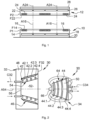
- An electrical energy transfer device 30 comprises a first part 32 as well as a second part 34, the first and second parts 32, 34 being movable relative to each other in a direction of approximation between a separated state , visible on the figure 2 , as well as a close state, visible on the Figure 3 , in which a transfer of electrical energy is carried out between the first and second parts 32, 34.
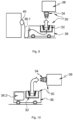
- the electrical energy transfer device 30 is used to ensure a transfer of electrical energy between a ground module 36 integrating the first part 32 and a flying vehicle 38, integrating the second part 34, which can be an airplane, a eVTOL type flying vehicle (for “electric vertical take-off and landing” in English), a drone or any other flying vehicle.
- the transfer of electrical energy can be used to recharge at least one electrical energy storage system present in the flying vehicle 38 and/or to power at least one electrical equipment present in the flying vehicle 38.
- the ground module 36 is static. According to other applications visible on the figures 9 and 10 , the ground module 36 is mobile and corresponds to a land vehicle. According to a configuration visible on the Figure 9 , the mobile ground module 36 is connected by an electrical cable 36.1 to a power supply 40 for power the first part 32 of the electrical energy transfer device 30. According to another configuration visible on the Figure 10 , the mobile ground module 36 comprises at least one rechargeable electrical energy storage system 36.2 to power the first part 32 of the electrical energy transfer device 30.
- the electrical energy transfer device 30 comprises a contactless electrical energy transfer system between a first electrical circuit C32 secured to the first part 32 and a second electrical circuit C34 secured to the second part 34.
- the first part 32 corresponds to an electrical energy transmitter system and the second part 34 corresponds to an electrical energy receiver system.
- the contactless energy transfer system comprises at least a first coil 42 secured to the first part 32 and connected to the first electrical circuit C32 as well as a second coil 44 secured to the second part 34 and connected to the second electrical circuit C34.
- the first part 32 comprises, in addition to the first coil 42, a first front face F32 substantially perpendicular to the direction of approximation, at least one layer of ferromagnetic elements 46, made of ferrite for example, as well as a first support 48 supporting the first coil 42 and the layer of ferromagnetic elements 46.
- the first part 32 may comprise at least one shielding plate.
- the second part 34 comprises a second support 50 supporting the second coil 44.
- the second part 34 may comprise at least one layer of ferromagnetic elements, made of ferrite for example, and at least one shielding plate.
- the first part 32 comprises a first housing 52 which opens at the level of the first front face F32 of the first part 32, comprising at least one first lateral surface 54 and configured to at least partially accommodate the second part 34.
- the first lateral surface 54 is a surface of revolution and has a first axis of revolution A54. As illustrated on the figures 2 to 4 , the first lateral surface 54 is frustoconical. According to other configurations, the first lateral surface 54 can be conical, cylindrical, or in the shape of a hemisphere.
- the first lateral surface 54 has oblong sections and comprises two portions of surface of revolution, each having an axis of revolution, connected by flat surfaces.
- the first lateral surface 54 comprises at least one portion of surface of revolution having a first axis of revolution A54.
- the first lateral surface 54 or only a portion of the first lateral surface 54 is a surface of revolution and has a first axis of revolution A54.
- the axis of revolution A54 is parallel to the direction of approach.
- a transverse plane is perpendicular to the first axis of revolution A54.
- this first axis of revolution A54 is perpendicular to the first front face F32 of the first part 32.
- the first housing 52 may comprise a bottom 56 substantially perpendicular to the axis of revolution A54.
- the first housing 52 or the first lateral surface 54 has cross sections (in planes perpendicular to the first axis of revolution A54) which decrease as they move away from the first front face F32. This configuration makes it possible to obtain self-centering when inserting the second part 34 into the first housing 52 of the first part 32.
- the housing 52 comprises two first lateral surfaces 54, including a first distal lateral surface spaced from the first frontal face F32, having cross sections which decrease away from the first frontal face F32 as well as a first surface lateral opening, adjacent to the first frontal face F32, positioned between the first distal lateral surface and the first frontal face F32, having constant cross sections.
- the first part 32 comprises a single first coil 42 which has several turns 42.1 to 42.4 wound at the level of the first lateral surface 54 and offset relative to each other in the direction of reconciliation.
- the turns 42.1 to 42.4 are regularly distributed according to the direction of ruzement.
- the first part 32 comprises several first coils 42 wound at the level of the first lateral surface 54, offset with respect to each other in the direction of ruzement.
- the first coils 42 are regularly distributed according to the direction of ruzement.
- the first support 48 is a block of material, for example resin, which has a first surface corresponding to the first front face F32 as well as a hollow corresponding to the first housing 52.
- the turns of the first coil 42 or the first coils 42 are completely embedded in the block of material of the first support 48 and offset towards the inside of the first support 48 relative to the first lateral surface 54 while being slightly spaced from said first lateral surface 54.
- the turns of the first coil 42 or the first coils 42 are partially embedded in the block of material of the first support 48 and positioned astride the first lateral surface 54.
- the turns of the first coil 42 or the first coils 42 are not embedded in the block of material of the first support 48 and offset towards the outside of the first support 48 relative to the first lateral surface 54 while being closely spaced of said first lateral surface 54.
- the turns of the first coil 42 or the first coils 42 are held immobile relative to the first part 32 by any appropriate holding system.
- the first part 32 comprises a layer of ferromagnetic elements 46
- the latter has a geometry substantially identical to the first lateral surface 54 except for one homothety.
- each turn of the first coil 42 or each first coil 42 is positioned inside the layer of ferromagnetic elements 46, between the axis of revolution A54 and the layer of ferromagnetic elements 46.
- the layer of The ferromagnetic elements 46 of the first part 32 surround the first lateral surface 54.
- Each turn of the first coil 42 or each first coil 42 is positioned between the layer of ferromagnetic elements 46 and the first lateral surface 54.
- the first part 32 comprises at least one cooling system 58 configured to maintain the layer of ferromagnetic elements 46 at a temperature below a given threshold.
- This cooling system 58 comprises a cooling circuit 60 which has an inlet of heat transfer fluid 60.1, an outlet of heat transfer fluid 60.2 as well as a section of circuit 60.3, wound at the level of the first lateral surface 54 between the turns of the first coil 42 or the first coils 42, embedded in the block of material of the first support 48.
- the first part 32 comprises at least one centering pin 62, oriented parallel to the direction of ruzement, which has a first end connected to the first part 32 as well as a second free end 62.1.
- the centering pin 62 is cylindrical and its free end 62.1 is positioned approximately in the same plane as the first front face F32 of the first part 32.
- the cylindrical centering pin 62 has an axis coincident with the first axis of revolution A54.
- At least one ferromagnetic element 63 is positioned in the centering pin 62.
- the second part 34 has at least one second lateral surface 64 substantially identical to the first surface 54 of the first housing 52 of the first part 32.
- the second lateral surface 64 has at least one second axis of revolution A64 and a second lateral surface 64 for each first lateral surface 54 of the housing 52 of the first part 32, each second lateral surface 64 being substantially identical to a homothety to the corresponding first lateral surface 54.
- the second part 34 has a general shape complementary to the shape of the first housing 52.
- the first and second lateral surfaces 54, 64 are arranged opposite each other, being spaced a distance apart. short distance substantially identical on all their surfaces.
- the second support 50 When the first housing 52 has a bottom 56, the second support 50 has a second front face 66 substantially perpendicular to the second axis of revolution A64. In the close state, the second front face 66 of the second support 50 is in contact with or slightly spaced from the bottom 56 of the first housing 52 of the first part 32.
- the second part 34 comprises a single second coil 44 which has several turns 44.1 to 44.4 wound at the level of the second lateral surface 64, offset with respect to each other in the direction of approximation.
- the turns 44.1 to 44.4 are regularly distributed according to the direction of ruzement.
- the second part 34 comprises several second coils 44 wound at the level of the second lateral surface 64, offset with respect to each other in the direction of ruzement.
- the second coils 44 are regularly distributed according to the direction of ruzement.
- the second support 50 is a block of material, for example resin, which has a first surface corresponding to the second front face 66 as well as a side face corresponding to the second side surface 64.
- the turns of the second coil 44 or the second coils 44 are completely embedded in the block of material of the second support 50 and offset towards the inside of the second support 50 relative to the second lateral surface 64, being slightly spaced from said second lateral surface 64.
- the turns of the second coil 44 or the second coils 44 are partially embedded in the block of material of the second support 50 and positioned astride the second lateral surface 64.
- the turns of the second coil 44 or the second coils 44 are not embedded in the block of material of the second support 50 and offset towards the outside of the second support 50 relative to the second lateral surface 64, being slightly spaced from said second lateral surface 64.
- the turns of the second coil 44 or the second coils 44 are positioned in a cavity 68 formed in the second support 50.
- the turns of the second coil 44 or the second coils 44 are held immobile relative to the first part 34 by any appropriate holding system.
- the second part 34 comprises a second housing 70 for each centering pin 62, configured to accommodate the latter in an adjusted manner.
- This second housing 70 comprises a cylindrical side wall having a diameter substantially identical to that of the centering pin 62. According to one arrangement, the second housing 70 has an axis coincident with the second axis of revolution A64.
- At least one of the first and second parts 32, 34 comprises a guide sensor 72 to assist in positioning the first and second parts 32, 34 relative to each other in a centered manner.
- the guidance sensor 72 is a positioning sensor.
- the guide sensor 72 is positioned at the level of the second free end 62.1 of the centering pin 62 of the first part 32.
- the second part 34 is at least partially housed in the first housing 52 of the first part 32 and the first and second coils 42, 44 are positioned opposite each other, the second coils 44 being positioned inside the first coils 44 centered.
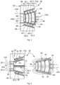
- the electrical energy transfer device 30 comprises at least one electrical energy transfer system with contact configured to ensure a transfer of electrical energy between a first electrical circuit C32 secured to the first part 32 and a second electrical circuit C34 in solidarity with the second part 34.
- the first part 32 comprises a first front face S32 as well as a first housing 52, opening at the level of the first front face F32 and comprising at least one first lateral surface 54, configured to receive at least partially the second part 34.
- the first lateral surface 54 comprises at least one portion of surface of revolution having a first axis of revolution A54.
- the first surface lateral 54 or only a portion of the first lateral surface 54 is a surface of revolution and has a first axis of revolution A54.
- this first axis of revolution A54 is perpendicular to the first front face F32 of the first part 32.
- the first housing 52 may comprise a bottom 56 substantially perpendicular to the axis of revolution A54.
- the first housing 52 or the first lateral surface 54 has cross sections (in planes perpendicular to the first axis of revolution A54) which decrease as they move away from the first front face F32. This configuration makes it possible to obtain self-centering when inserting the second part 34 into the first housing 52 of the first part 32.
- the housing 52 comprises two first side surfaces 54, 54', a first distal side surface 54, spaced from the first front face F32, having cross sections which decrease away from the first front face F32 as well as a first opening lateral surface 54', adjacent to the first frontal face F32, positioned between the first distal lateral surface 54 and the first frontal face F32, having constant cross sections.
- the first distal lateral surface 54 is half-spherical and the first emerging lateral surface 54' is cylindrical.
- the first distal lateral surface 54 is conical and the first emerging lateral surface 54' is cylindrical.
- the housing 52 comprises a single first lateral surface 54, for example frustoconical.
- the second part 34 has at least one second lateral surface 64 substantially identical to the first lateral surface 54 of the first housing 52 of the first part 32.
- the second lateral surface 64 has at least one second axis of revolution A64 and has a second lateral surface 64 for each first lateral surface 54 of the housing 52 of the first part 32, each second lateral surface 64 being substantially identical up to one scale to the corresponding first lateral surface 54.
- the first and second lateral surfaces 54, 64 are arranged opposite each other, being spaced a distance apart. short distance substantially identical on all their surfaces.
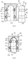
- the electrical energy transfer system with contact comprises at least one helical spring in the shape of a torus 74 and connected to the first or second electrical circuit C32, C34 which, when the first and second parts 32, 34 are in the close state as illustrated on the Figure 6 , is inserted between the first and second lateral surfaces 54, 64 of the first and second parts 32, 34 and ensures electrical continuity between the first and second electrical circuits C32, C34 of the first and second parts 32, 34.
- At least one of the first and second parts 32, 34 comprises a peripheral groove 76, positioned at a first or second lateral surface 54, 64, configured to partially accommodate the helical spring in the shape of a torus 74 so that the latter projects relative to the first or second lateral surface 54, 64.
- the peripheral groove 76 is provided on the first part 32.
- the electrical energy transfer system with contact comprises a contact terminal 78 connected to a first or second electrical circuit C32, C34 different from that to which the torus-shaped helical spring 74 is connected.
- the latter and the contact terminal 78 are arranged so that the torus-shaped helical spring 74 is in contact with the contact terminal 78 when the first and second parts 32, 34 are in the close state.
- the contact terminal 78 is a ring which extends over the entire circumference of the first or second lateral surface 54, 64.
- the first part 32 comprises the peripheral groove 76 and the torus-shaped helical spring 74 is connected to the first electrical circuit C32 of the first part 32.
- the contact terminal 78 is integral with the second part 34 and connected to the second electrical circuit C34 of the second part 34.
- the second part 34 comprises the peripheral groove 76 and the torus-shaped helical spring 74 is connected to the second electrical circuit 34 of the second part 34.
- contact terminal 78 is integral with the first part 32 and connected to the first electrical circuit C32 of the first part 32.
- the invention is not limited to this embodiment to ensure the stationary holding of the torus-shaped helical spring 74 relative to the first or second part 32, 34 to which it is connected.
- the peripheral groove 76 can be replaced by any suitable holding system.
- the electrical energy transfer device 30 comprises several electrical energy transfer systems with contact each comprising a torus-shaped helical spring 74, the different torus-shaped helical springs 74 being offset relative to each other according to the direction of reconciliation.
- the first part 32 may comprise a centering pin 62 and the second part 34 may comprise a second housing 70, as for the first variant.
- the electrical energy transfer device 30 comprises at least one locking system 80 configured to maintain the first and second parts in the close state. This embodiment can be applied equally to the first and second variants.
- the locking system 80 comprises a torus-shaped helical spring 82 which, when the first and second parts 32, 34 are in the close state as illustrated in the Figure 6 , is interposed between the first and second side surfaces 54, 64 of the first and second parts 32, 34; a first peripheral groove 84, positioned at the level of the first lateral surface 54 of the first part 32, configured to partially accommodate the torus-shaped helical spring 82, at least in the close state, so that the latter is projecting relative to the first lateral surface 54 as well as a second peripheral groove 86, positioned at the level of the second lateral surface 64 of the second part 34, configured to partially accommodate the torus-shaped helical spring 82, at least at the close state, so that the latter projects relative to the second lateral surface 64.
- the first and second peripheral grooves 84, 86 are positioned opposite each other when the first and second parts 32, 34 are in close condition.
- the torus-shaped helical spring 82 in the close state, is positioned astride the first and second peripheral grooves 84, 86.
- the torus-shaped helical spring 82 in the spaced state, is carried by the first part 32. It is configured to compress elastically to allow the introduction of the second part 34 into the housing 52 of the first part 32 and return to an uncompressed state when the first and second peripheral grooves 84 , 86 are arranged facing each other and the first and second parts 32, 34 in the close state.
- the energy transfer device comprises at least a first electrical energy transfer element (among a turn of a first coil 42, a first coil 42, a torus-shaped helical spring 74 or a contact terminal 78) connected to the first electrical circuit C32 and positioned at the level of the first lateral surface 54 of the first part 32 as well as at least a second electrical energy transfer element (among a turn of a first coil 42, a first coil 42, a torus-shaped helical spring 74 or a contact terminal 78) connected to the second electrical circuit C34, positioned at the level of the second lateral surface 64 of the second part 32 and approximately centered with respect to a first energy transfer element when the first and second parts 32, 34 are in the close state, the first and second electrical energy transfer elements being configured to ensure a transfer of electrical energy between them in the state close.
- the first and second parts 32, 34 are necessarily positioned so as to ensure optimal electrical energy transfer thanks to the housing 52 which makes it possible to center the first and second electrical energy transfer element
Landscapes
- Engineering & Computer Science (AREA)
- Power Engineering (AREA)
- Transportation (AREA)
- Mechanical Engineering (AREA)
- Computer Networks & Wireless Communication (AREA)
- Charge And Discharge Circuits For Batteries Or The Like (AREA)
- Current-Collector Devices For Electrically Propelled Vehicles (AREA)
- Transmission Devices (AREA)
- Battery Mounting, Suspending (AREA)
Applications Claiming Priority (1)
| Application Number | Priority Date | Filing Date | Title |
|---|---|---|---|
| FR2208460 | 2022-08-23 |
Publications (3)
| Publication Number | Publication Date |
|---|---|
| EP4339010A2 true EP4339010A2 (de) | 2024-03-20 |
| EP4339010A3 EP4339010A3 (de) | 2024-05-22 |
| EP4339010B1 EP4339010B1 (de) | 2025-01-01 |
Family
ID=83506560
Family Applications (1)
| Application Number | Title | Priority Date | Filing Date |
|---|---|---|---|
| EP23181030.0A Active EP4339010B1 (de) | 2022-08-23 | 2023-06-22 | Vorrichtung zur übertragung elektrischer energie mit einem zentriersystem |
Country Status (3)
| Country | Link |
|---|---|
| US (1) | US12214687B2 (de) |
| EP (1) | EP4339010B1 (de) |
| CN (1) | CN117639300A (de) |
Family Cites Families (9)
| Publication number | Priority date | Publication date | Assignee | Title |
|---|---|---|---|---|
| JP2000114079A (ja) * | 1998-10-01 | 2000-04-21 | Harness Syst Tech Res Ltd | 電磁誘導型コネクタ |
| DE10055090A1 (de) * | 2000-11-07 | 2002-05-08 | Conducta Endress & Hauser | Steckverbinder zum Anschluss einer Übertragungsleitung an mindestens einen Sensor |
| JP3864094B2 (ja) * | 2002-01-10 | 2006-12-27 | Fdk株式会社 | 非接触給電カプラ |
| EP2581993B1 (de) * | 2011-10-13 | 2014-06-11 | TE Connectivity Nederland B.V. | Kontaktlose Steckdose und kontaktloses Steckdosensystem |
| JP5852873B2 (ja) * | 2011-12-16 | 2016-02-03 | Udトラックス株式会社 | 非接触給電システム |
| US8971072B2 (en) * | 2011-12-30 | 2015-03-03 | Bedrock Automation Platforms Inc. | Electromagnetic connector for an industrial control system |
| EP2770645B1 (de) * | 2013-02-21 | 2018-01-31 | Nxp B.V. | Nichtgalavnischer Verbinder |
| JP2019045163A (ja) * | 2017-08-30 | 2019-03-22 | 日立Geニュークリア・エナジー株式会社 | 無人移動体を用いた構造体点検システム及び構造体点検方法 |
| JP7015734B2 (ja) * | 2018-05-14 | 2022-02-03 | 株式会社東芝 | 送電装置、移動体および無線電力伝送装置 |
-
2023
- 2023-06-22 EP EP23181030.0A patent/EP4339010B1/de active Active
- 2023-08-03 CN CN202310972080.6A patent/CN117639300A/zh active Pending
- 2023-08-21 US US18/452,786 patent/US12214687B2/en active Active
Also Published As
| Publication number | Publication date |
|---|---|
| US20240067020A1 (en) | 2024-02-29 |
| CN117639300A (zh) | 2024-03-01 |
| EP4339010A3 (de) | 2024-05-22 |
| US12214687B2 (en) | 2025-02-04 |
| EP4339010B1 (de) | 2025-01-01 |
Similar Documents
| Publication | Publication Date | Title |
|---|---|---|
| EP2667459B1 (de) | Anordnung von elektrischen Steckdosen | |
| WO2012032230A1 (fr) | Ensemble de prises electriques | |
| FR3079627A1 (fr) | Dispositif optique pour vehicule comprenant un element de chauffage | |
| EP3636481B1 (de) | Automatische entkoppelungsvorrichtug eines in eine steckdose eines elektrofahrzeugs eingesteckten steckverbinders | |
| WO2010061063A1 (fr) | Systeme d'assemblage de modules d'energie electrique | |
| EP3400147A1 (de) | Sicherheitssystem für eine elektromechanische kopplungsanordnung, ladestation für ein elektrofahrzeug mit solch einem system und zugehöriges kopplungsverfahren | |
| EP2616291A1 (de) | Kraftfahrzeugstruktur mit entfernbarem akkumulator | |
| EP4209384A1 (de) | Kontaktlose stromübertragungsvorrichtung, luftfahrzeug mit wiederaufladbaren batterien und elektrische ladebasis mit der stromübertragungsvorrichtung | |
| EP4339010B1 (de) | Vorrichtung zur übertragung elektrischer energie mit einem zentriersystem | |
| EP0580469B1 (de) | Steckverbindersatz und Befestigungsfläche insbesondere für die Avionik | |
| FR2870049A1 (fr) | Element boitier avec partie connecteur | |
| FR2998411A1 (fr) | Dispositif d'alimentation electrique sans fil d'equipements installes a l'interieur d'un aeronef | |
| FR3048560B1 (fr) | Ensemble de rechargement d'une batterie et procede de recharge mettant en oeuvre un tel ensemble | |
| WO2017084928A1 (fr) | Prise et fiche electriques pour le rechargement d'un vehicule electrique | |
| EP4077033B1 (de) | Verfahren zum verbinden eines elektrischen ausgangs eines fahrzeugs mit einem steckverbinder aufweisend eine magnetisierungsoberfläche | |
| EP3772760A1 (de) | Speichervorrichtung für elektrische energie, die an der aussenseite eines fahrzeugs vom typ fahrrad oder elektroroller befestigt werden kann | |
| EP3879050B1 (de) | Schnittstellenadapter mit integrierter magnetischer verriegelung, der mindestens einen akkumulator aufnimmt oder durch diesen gebildet wird und dessen magnetische befestigung mit elektrischer leitung an einer stromschiene (b1) gewährleistet | |
| FR2699673A1 (fr) | Perfectionnement aux capteurs de température comportant une thermistance. | |
| EP0024235B1 (de) | Verbinder für optische Fasern | |
| FR2926019A1 (fr) | Fauteuil roulant motorise a batterie integree | |
| FR3125174A1 (fr) | Dispositif de connexion électrique comportant des embouts mis bout à bout | |
| EP0442411B1 (de) | Konische Feder für einen elektrischen Kontakt | |
| WO2023175272A1 (fr) | Connecteur pour un réseau de distribution électrique d'un aéronef | |
| EP2903091A1 (de) | System zur elektrischen Verbindung mindestens eines Geräts mit einem zweiten Gerät | |
| EP3923401B1 (de) | Elektrische batterie einschliesslich einer vorrichtung zur homogenisierung der innentemperatur |
Legal Events
| Date | Code | Title | Description |
|---|---|---|---|
| PUAI | Public reference made under article 153(3) epc to a published international application that has entered the european phase |
Free format text: ORIGINAL CODE: 0009012 |
|
| STAA | Information on the status of an ep patent application or granted ep patent |
Free format text: STATUS: REQUEST FOR EXAMINATION WAS MADE |
|
| 17P | Request for examination filed |
Effective date: 20230622 |
|
| AK | Designated contracting states |
Kind code of ref document: A2 Designated state(s): AL AT BE BG CH CY CZ DE DK EE ES FI FR GB GR HR HU IE IS IT LI LT LU LV MC ME MK MT NL NO PL PT RO RS SE SI SK SM TR |
|
| PUAL | Search report despatched |
Free format text: ORIGINAL CODE: 0009013 |
|
| STAA | Information on the status of an ep patent application or granted ep patent |
Free format text: STATUS: EXAMINATION IS IN PROGRESS |
|
| AK | Designated contracting states |
Kind code of ref document: A3 Designated state(s): AL AT BE BG CH CY CZ DE DK EE ES FI FR GB GR HR HU IE IS IT LI LT LU LV MC ME MK MT NL NO PL PT RO RS SE SI SK SM TR |
|
| RIC1 | Information provided on ipc code assigned before grant |
Ipc: B60L 53/35 20190101ALI20240417BHEP Ipc: H02J 50/10 20160101ALI20240417BHEP Ipc: B60L 53/34 20190101ALI20240417BHEP Ipc: B60L 53/302 20190101ALI20240417BHEP Ipc: B60L 53/12 20190101AFI20240417BHEP |
|
| 17Q | First examination report despatched |
Effective date: 20240506 |
|
| GRAP | Despatch of communication of intention to grant a patent |
Free format text: ORIGINAL CODE: EPIDOSNIGR1 |
|
| STAA | Information on the status of an ep patent application or granted ep patent |
Free format text: STATUS: GRANT OF PATENT IS INTENDED |
|
| INTG | Intention to grant announced |
Effective date: 20241008 |
|
| GRAS | Grant fee paid |
Free format text: ORIGINAL CODE: EPIDOSNIGR3 |
|
| GRAA | (expected) grant |
Free format text: ORIGINAL CODE: 0009210 |
|
| STAA | Information on the status of an ep patent application or granted ep patent |
Free format text: STATUS: THE PATENT HAS BEEN GRANTED |
|
| AK | Designated contracting states |
Kind code of ref document: B1 Designated state(s): AL AT BE BG CH CY CZ DE DK EE ES FI FR GB GR HR HU IE IS IT LI LT LU LV MC ME MK MT NL NO PL PT RO RS SE SI SK SM TR |
|
| RBV | Designated contracting states (corrected) |
Designated state(s): AL AT BE BG CH CY CZ DE DK EE ES FI FR GB GR HR HU IE IS IT LI LT LU LV MC ME MK MT NL NO PL PT RO RS SE SI SK SM TR |
|
| REG | Reference to a national code |
Ref country code: GB Ref legal event code: FG4D Free format text: NOT ENGLISH |
|
| REG | Reference to a national code |
Ref country code: DE Ref legal event code: R096 Ref document number: 602023001571 Country of ref document: DE |
|
| REG | Reference to a national code |
Ref country code: CH Ref legal event code: EP |
|
| REG | Reference to a national code |
Ref country code: IE Ref legal event code: FG4D Free format text: LANGUAGE OF EP DOCUMENT: FRENCH |
|
| REG | Reference to a national code |
Ref country code: LT Ref legal event code: MG9D |
|
| REG | Reference to a national code |
Ref country code: NL Ref legal event code: MP Effective date: 20250101 |
|
| REG | Reference to a national code |
Ref country code: AT Ref legal event code: MK05 Ref document number: 1755922 Country of ref document: AT Kind code of ref document: T Effective date: 20250101 |
|
| PG25 | Lapsed in a contracting state [announced via postgrant information from national office to epo] |
Ref country code: NL Free format text: LAPSE BECAUSE OF FAILURE TO SUBMIT A TRANSLATION OF THE DESCRIPTION OR TO PAY THE FEE WITHIN THE PRESCRIBED TIME-LIMIT Effective date: 20250101 |
|
| PG25 | Lapsed in a contracting state [announced via postgrant information from national office to epo] |
Ref country code: FI Free format text: LAPSE BECAUSE OF FAILURE TO SUBMIT A TRANSLATION OF THE DESCRIPTION OR TO PAY THE FEE WITHIN THE PRESCRIBED TIME-LIMIT Effective date: 20250101 |
|
| PG25 | Lapsed in a contracting state [announced via postgrant information from national office to epo] |
Ref country code: PL Free format text: LAPSE BECAUSE OF FAILURE TO SUBMIT A TRANSLATION OF THE DESCRIPTION OR TO PAY THE FEE WITHIN THE PRESCRIBED TIME-LIMIT Effective date: 20250101 |
|
| PGFP | Annual fee paid to national office [announced via postgrant information from national office to epo] |
Ref country code: DE Payment date: 20250618 Year of fee payment: 3 |
|
| PG25 | Lapsed in a contracting state [announced via postgrant information from national office to epo] |
Ref country code: ES Free format text: LAPSE BECAUSE OF FAILURE TO SUBMIT A TRANSLATION OF THE DESCRIPTION OR TO PAY THE FEE WITHIN THE PRESCRIBED TIME-LIMIT Effective date: 20250101 |
|
| PG25 | Lapsed in a contracting state [announced via postgrant information from national office to epo] |
Ref country code: IS Free format text: LAPSE BECAUSE OF FAILURE TO SUBMIT A TRANSLATION OF THE DESCRIPTION OR TO PAY THE FEE WITHIN THE PRESCRIBED TIME-LIMIT Effective date: 20250501 Ref country code: NO Free format text: LAPSE BECAUSE OF FAILURE TO SUBMIT A TRANSLATION OF THE DESCRIPTION OR TO PAY THE FEE WITHIN THE PRESCRIBED TIME-LIMIT Effective date: 20250401 |
|
| PG25 | Lapsed in a contracting state [announced via postgrant information from national office to epo] |
Ref country code: HR Free format text: LAPSE BECAUSE OF FAILURE TO SUBMIT A TRANSLATION OF THE DESCRIPTION OR TO PAY THE FEE WITHIN THE PRESCRIBED TIME-LIMIT Effective date: 20250101 |
|
| PG25 | Lapsed in a contracting state [announced via postgrant information from national office to epo] |
Ref country code: PT Free format text: LAPSE BECAUSE OF FAILURE TO SUBMIT A TRANSLATION OF THE DESCRIPTION OR TO PAY THE FEE WITHIN THE PRESCRIBED TIME-LIMIT Effective date: 20250502 Ref country code: LV Free format text: LAPSE BECAUSE OF FAILURE TO SUBMIT A TRANSLATION OF THE DESCRIPTION OR TO PAY THE FEE WITHIN THE PRESCRIBED TIME-LIMIT Effective date: 20250101 |
|
| PGFP | Annual fee paid to national office [announced via postgrant information from national office to epo] |
Ref country code: FR Payment date: 20250627 Year of fee payment: 3 |
|
| PG25 | Lapsed in a contracting state [announced via postgrant information from national office to epo] |
Ref country code: BG Free format text: LAPSE BECAUSE OF FAILURE TO SUBMIT A TRANSLATION OF THE DESCRIPTION OR TO PAY THE FEE WITHIN THE PRESCRIBED TIME-LIMIT Effective date: 20250101 Ref country code: GR Free format text: LAPSE BECAUSE OF FAILURE TO SUBMIT A TRANSLATION OF THE DESCRIPTION OR TO PAY THE FEE WITHIN THE PRESCRIBED TIME-LIMIT Effective date: 20250402 |
|
| PG25 | Lapsed in a contracting state [announced via postgrant information from national office to epo] |
Ref country code: AT Free format text: LAPSE BECAUSE OF FAILURE TO SUBMIT A TRANSLATION OF THE DESCRIPTION OR TO PAY THE FEE WITHIN THE PRESCRIBED TIME-LIMIT Effective date: 20250101 |
|
| PG25 | Lapsed in a contracting state [announced via postgrant information from national office to epo] |
Ref country code: CZ Free format text: LAPSE BECAUSE OF FAILURE TO SUBMIT A TRANSLATION OF THE DESCRIPTION OR TO PAY THE FEE WITHIN THE PRESCRIBED TIME-LIMIT Effective date: 20250101 |
|
| PG25 | Lapsed in a contracting state [announced via postgrant information from national office to epo] |
Ref country code: SE Free format text: LAPSE BECAUSE OF FAILURE TO SUBMIT A TRANSLATION OF THE DESCRIPTION OR TO PAY THE FEE WITHIN THE PRESCRIBED TIME-LIMIT Effective date: 20250101 |
|
| REG | Reference to a national code |
Ref country code: DE Ref legal event code: R097 Ref document number: 602023001571 Country of ref document: DE |
|
| PG25 | Lapsed in a contracting state [announced via postgrant information from national office to epo] |
Ref country code: SM Free format text: LAPSE BECAUSE OF FAILURE TO SUBMIT A TRANSLATION OF THE DESCRIPTION OR TO PAY THE FEE WITHIN THE PRESCRIBED TIME-LIMIT Effective date: 20250101 |
|
| PG25 | Lapsed in a contracting state [announced via postgrant information from national office to epo] |
Ref country code: DK Free format text: LAPSE BECAUSE OF FAILURE TO SUBMIT A TRANSLATION OF THE DESCRIPTION OR TO PAY THE FEE WITHIN THE PRESCRIBED TIME-LIMIT Effective date: 20250101 |
|
| PG25 | Lapsed in a contracting state [announced via postgrant information from national office to epo] |
Ref country code: IT Free format text: LAPSE BECAUSE OF FAILURE TO SUBMIT A TRANSLATION OF THE DESCRIPTION OR TO PAY THE FEE WITHIN THE PRESCRIBED TIME-LIMIT Effective date: 20250101 |
|
| PG25 | Lapsed in a contracting state [announced via postgrant information from national office to epo] |
Ref country code: EE Free format text: LAPSE BECAUSE OF FAILURE TO SUBMIT A TRANSLATION OF THE DESCRIPTION OR TO PAY THE FEE WITHIN THE PRESCRIBED TIME-LIMIT Effective date: 20250101 |
|
| PG25 | Lapsed in a contracting state [announced via postgrant information from national office to epo] |
Ref country code: RO Free format text: LAPSE BECAUSE OF FAILURE TO SUBMIT A TRANSLATION OF THE DESCRIPTION OR TO PAY THE FEE WITHIN THE PRESCRIBED TIME-LIMIT Effective date: 20250101 |
|
| PG25 | Lapsed in a contracting state [announced via postgrant information from national office to epo] |
Ref country code: SK Free format text: LAPSE BECAUSE OF FAILURE TO SUBMIT A TRANSLATION OF THE DESCRIPTION OR TO PAY THE FEE WITHIN THE PRESCRIBED TIME-LIMIT Effective date: 20250101 |
|
| PLBE | No opposition filed within time limit |
Free format text: ORIGINAL CODE: 0009261 |
|
| STAA | Information on the status of an ep patent application or granted ep patent |
Free format text: STATUS: NO OPPOSITION FILED WITHIN TIME LIMIT |
|
| 26N | No opposition filed |
Effective date: 20251002 |
|
| PG25 | Lapsed in a contracting state [announced via postgrant information from national office to epo] |
Ref country code: MC Free format text: LAPSE BECAUSE OF FAILURE TO SUBMIT A TRANSLATION OF THE DESCRIPTION OR TO PAY THE FEE WITHIN THE PRESCRIBED TIME-LIMIT Effective date: 20250101 |